EP3733512B1 - Method and device for lifting a load - Google Patents
Method and device for lifting a load Download PDFInfo
- Publication number
- EP3733512B1 EP3733512B1 EP20182196.4A EP20182196A EP3733512B1 EP 3733512 B1 EP3733512 B1 EP 3733512B1 EP 20182196 A EP20182196 A EP 20182196A EP 3733512 B1 EP3733512 B1 EP 3733512B1
- Authority
- EP
- European Patent Office
- Prior art keywords
- drone
- load
- crane
- aerial
- hydrostatic
- Prior art date
- Legal status (The legal status is an assumption and is not a legal conclusion. Google has not performed a legal analysis and makes no representation as to the accuracy of the status listed.)
- Active
Links
Images


Classifications
-
- B—PERFORMING OPERATIONS; TRANSPORTING
- B64—AIRCRAFT; AVIATION; COSMONAUTICS
- B64D—EQUIPMENT FOR FITTING IN OR TO AIRCRAFT; FLIGHT SUITS; PARACHUTES; ARRANGEMENT OR MOUNTING OF POWER PLANTS OR PROPULSION TRANSMISSIONS IN AIRCRAFT
- B64D1/00—Dropping, ejecting, releasing or receiving articles, liquids, or the like, in flight
- B64D1/22—Taking-up articles from earth's surface
-
- B—PERFORMING OPERATIONS; TRANSPORTING
- B66—HOISTING; LIFTING; HAULING
- B66C—CRANES; LOAD-ENGAGING ELEMENTS OR DEVICES FOR CRANES, CAPSTANS, WINCHES, OR TACKLES
- B66C13/00—Other constructional features or details
- B66C13/04—Auxiliary devices for controlling movements of suspended loads, or preventing cable slack
-
- B—PERFORMING OPERATIONS; TRANSPORTING
- B64—AIRCRAFT; AVIATION; COSMONAUTICS
- B64U—UNMANNED AERIAL VEHICLES [UAV]; EQUIPMENT THEREFOR
- B64U30/00—Means for producing lift; Empennages; Arrangements thereof
- B64U30/20—Rotors; Rotor supports
-
- G—PHYSICS
- G05—CONTROLLING; REGULATING
- G05D—SYSTEMS FOR CONTROLLING OR REGULATING NON-ELECTRIC VARIABLES
- G05D1/00—Control of position, course, altitude or attitude of land, water, air or space vehicles, e.g. using automatic pilots
- G05D1/10—Simultaneous control of position or course in three dimensions
-
- G—PHYSICS
- G05—CONTROLLING; REGULATING
- G05D—SYSTEMS FOR CONTROLLING OR REGULATING NON-ELECTRIC VARIABLES
- G05D1/00—Control of position, course, altitude or attitude of land, water, air or space vehicles, e.g. using automatic pilots
- G05D1/10—Simultaneous control of position or course in three dimensions
- G05D1/101—Simultaneous control of position or course in three dimensions specially adapted for aircraft
- G05D1/104—Simultaneous control of position or course in three dimensions specially adapted for aircraft involving a plurality of aircrafts, e.g. formation flying
-
- G—PHYSICS
- G05—CONTROLLING; REGULATING
- G05D—SYSTEMS FOR CONTROLLING OR REGULATING NON-ELECTRIC VARIABLES
- G05D1/00—Control of position, course, altitude or attitude of land, water, air or space vehicles, e.g. using automatic pilots
- G05D1/60—Intended control result
- G05D1/69—Coordinated control of the position or course of two or more vehicles
- G05D1/695—Coordinated control of the position or course of two or more vehicles for maintaining a fixed relative position of the vehicles, e.g. for convoy travelling or formation flight
-
- B—PERFORMING OPERATIONS; TRANSPORTING
- B64—AIRCRAFT; AVIATION; COSMONAUTICS
- B64U—UNMANNED AERIAL VEHICLES [UAV]; EQUIPMENT THEREFOR
- B64U2101/00—UAVs specially adapted for particular uses or applications
- B64U2101/60—UAVs specially adapted for particular uses or applications for transporting passengers; for transporting goods other than weapons
- B64U2101/64—UAVs specially adapted for particular uses or applications for transporting passengers; for transporting goods other than weapons for parcel delivery or retrieval
-
- B—PERFORMING OPERATIONS; TRANSPORTING
- B64—AIRCRAFT; AVIATION; COSMONAUTICS
- B64U—UNMANNED AERIAL VEHICLES [UAV]; EQUIPMENT THEREFOR
- B64U2201/00—UAVs characterised by their flight controls
- B64U2201/10—UAVs characterised by their flight controls autonomous, i.e. by navigating independently from ground or air stations, e.g. by using inertial navigation systems [INS]
- B64U2201/102—UAVs characterised by their flight controls autonomous, i.e. by navigating independently from ground or air stations, e.g. by using inertial navigation systems [INS] adapted for flying in formations
-
- B—PERFORMING OPERATIONS; TRANSPORTING
- B64—AIRCRAFT; AVIATION; COSMONAUTICS
- B64U—UNMANNED AERIAL VEHICLES [UAV]; EQUIPMENT THEREFOR
- B64U50/00—Propulsion; Power supply
- B64U50/10—Propulsion
- B64U50/11—Propulsion using internal combustion piston engines
Definitions
- the present invention relates to a method and a device for lifting a load, with at least one aerial drone carrying at least part of the load.
- flying drones have been used in construction sites and other crane applications, such as container cranes or harbor cranes, primarily for additional auxiliary functions, in particular to fly cameras or similar imaging monitoring devices into position in order to monitor the crane operation or the lifting process carried out by the crane .
- the image provided by the camera attached to the flying drone can be displayed on a screen in the crane operator's cab in order to give the crane operator a different perspective on the crane hook.
- the load to which the flying drone is connected exerts considerable forces on the flying drone, which not only pull statically in the vertical direction, but also have horizontal components and can vary, for example, due to gusts of wind.
- pendulum movements and thus dynamic forces from the load can quickly move the drone into undesired positions or cause it to move.
- the present invention is based on the object of creating an improved method and an improved device for lifting loads using a flying drone, which avoid the disadvantages of the prior art and further develop the latter in an advantageous manner.
- simple control of the flying drone should be achieved even under the influence of the load associated with the flying drone.
- the load is divided between several flying drones.
- the load is connected to a further flying drone and is partially carried and/or directed by the further flying drone, the two flying drones being connected to one another by a common control device
- Controlling flight movements can be controlled in a coordinated manner. If the control device is actuated, for example, to fly an aircraft drone, a coordinated control signal is automatically generated in order to move the other aircraft drone in a corresponding manner.
- a load is lifted by a crane, for example in the form of a tower crane, a mobile telescopic crane or a harbor crane
- several flying drones can be connected to the crane hook at the same time on the load to be lifted or can also be connected directly to the crane hook in order to lift in different ways to help the burden.
- the load to be lifted can be lightened for the crane, for example in order to be able to lift a load that exceeds the load capacity or load capacity of the crane, so that the construction site operator can avoid having to set up a crane that is larger for this lifting task.
- the Flying drones can therefore perform a pure lifting function and lift a load together with a crane.
- Multiple flying drones can carry the load or be connected to the load hook, whereby it may be advantageous, for example, to have at least one pair of flying drones on opposite sides of the load hook position and connect to the load or the load hook itself in order to be able to exert horizontal forces in approximately opposite directions on the load hook or the load attached to it or to be able to compensate for each other if, for example, only the lifting ability of the flying drones is required.
- the shared control system can keep the two flying drones at a distance from each other and fly together along a specific flight path to a destination.
- the flying drones can, for example, be attached to the common load via separate lifting ropes, or can also be attached to a common lifting yoke, to which the load is in turn attached.
- the flying drones according to the invention each have a hydrostatic drive train for driving at least one rotor of the flying drone, such a hydrostatic drive train being able to comprise a hydrostat that works as a pump and can be connected to a drive motor, and one or more hydrostats that work as a motor can and can each be connected to a rotor in order to drive it and from as Pump working hydrostats are supplied.
- the torque provided on a rotor and/or its speed can be varied very quickly by varying one or more hydrostatic manipulated variables in the form of the displacement volume of one or more hydrostats and/or the adjustment angle of one or more adjustable hydrostats.
- Such rapid adjustment of the torque and/or the speed is also available when working at a high performance level with large torques and/or high speeds in order to lift high loads.
- such a hydrostatic drive system enables the mentioned sensitive, rapid controllability of torque and/or speed individually for each rotor.
- several hydrostats can be provided, each of which is connected to one of the rotors in order to drive the respective rotor, so that the speed and/or the torque of the respective rotor can be adjusted individually by adjusting the respective hydrostat - which can be done individually.
- the drive motor which drives a hydrostat working as a pump
- Such an internal combustion engine can provide a sufficiently high performance, even over longer operating times, in order to achieve sufficient load capacities for the drone to lift larger loads.
- the lifting and/or pulling force and/or the flight path of the flying drone can be controlled by adjusting a hydrostatic manipulated variable of the hydrostatic transmission or the hydrostatic drive train, in particular exclusively by adjusting one or more hydrostatic manipulated variables.
- such a flying drone with a hydrostatic drive train can work together with a ground supply station, which can be coupled to the flying drone.
- a supply station on the ground can include a cooling and/or filtering unit, which can be coupled to the hydrostatic supply circuit of the hydrostatic drive train and can cool and/or filter the hydraulic fluid of the hydrostatic drive train of the flight drone.
- said supply station can also include a pressure source that can be coupled to the hydrostatic drive train of the drone and can bias the hydrostatic drive train, in particular can provide and/or set a desired target operating pressure there.
- the aforementioned common control device can have a main control unit with input means, from which control signals are sent to the at least on the basis of the movement requests entered a flying drone and/or the crane are generated and transmitted, and have an additional control unit from which control commands for at least one further flying drone are generated and transmitted depending on the flight or crane movements that were initiated by the main control unit.
- the additional control unit mentioned can be connected to the main control unit and designed to automatically generate control signals adapted to it for the additionally used flying drone depending on the control signals generated by the main control unit.
- the additional control unit mentioned can include a sequence control module, by means of which the additional flight drone is controlled so that it The flight movements of a main drone automatically follow, without the machine operator having to specifically enter movement requests for the additional flight drone.
- said additional control unit can be designed in such a way that the additional flight drone can not only maintain a desired relative position relative to the crane or said main drone, but that said relative position can also be variably predetermined and changed, for example in such a way that said relative position continuously changed during a lifting process.
- the additional control unit for the additional flying drone can specify a specific path relative to the crane that the flying drone flies during a lifting process or depending on the position of the load hook.
- the additional control unit can determine a flight path for the flight drone, which can, for example, have its starting point approximately vertically under the crane boom and then, in order to rotate the elongated support relative to the crane boom during the lifting movement of the load hook, can extend helically around a vertical through the trolley of the crane.
- the flying drone can also be controlled depending on a position of another drone in such a way that the flying drone automatically follows movements of a lead drone and at least approximately maintains a desired position relative to the lead drone even during lead drone movements .tried to keep and follows.
- the flying drone can also be remotely controlled autonomously in such a way that the flying drone can freely fly to various desired positions in relation to the lead drone.
- the flying drone can also be flown completely freely relative to a guide drone, for example with the help of a joystick, in order to fly the flying drone until a desired relative position is reached.
- the common control device can then automatically hold or attempt to hold the relative position approached and follow any lifting movements of the lead drone.
- the flying drone can be position-controlled in a relative or lead drone-fixed coordinate system.
- a position determination device can be provided which determines the flight position of the Flight drone is determined continuously or cyclically relative to the lead drone, such a position determination device being able to have, for example, a signal locating device which can locate and/or evaluate signals coming from the flight drone and/or sent to the flight drone with regard to certain signal properties in order to determine the relative position of the flight drone to be designated as the lead drone.
- Such a signal locating device can, for example, be implemented in such a way that several transceiver units are attached to the control drone, which communicate with a transceiver unit on the flight drone, so that from the signal transit times and / or signal strengths and / or signal directions in the sense of the connecting lines between the various crane or machine-side transmitter/receiver units to the transmitter/receiver unit of the flying drone whose position can be determined relative to the lead drone.
- the transmitter/receiver units mentioned can be, for example, transponders or short-range transmitter/receiver units.
- the transmitter/receiver units mentioned can be attached, for example, to the boom, to the trolley, to the tower and/or to the load hook itself.
- the signal transit times from the respective transmitter/receiver unit on the crane or the machine to the flying drones and/or back from the flying drones to the machine-side transmitter/receiver unit can be determined and/or signal strengths can be recorded and/or the directions in which maximum signal strengths occur, are determined in order to determine the position of the flying drones relative to the crane from the signal transit times and / or signal strengths and / or signal directions of maximum signal strength.
- the absolute position determination mentioned can be carried out, for example, by means of a positioning system, for example a GPS system.
- the flying drones on the one hand and the load hook on the other hand can each be equipped with a GPS unit in order to determine, on the one hand, the absolute spatial position of the load hook and, on the other hand, the absolute spatial position of the flying drones.
- the spatial position of the load hook can also be determined approximately from the known movement and/or position data of the work machine components, such as the rotation angle of a tower crane, the trolley position and the load hook height, from which at least approximately, given a known installation location, in particular neglecting pendulum movements and /or wind influences, the load hook position can be determined.
- the position control of the flying drones can also be controlled depending on work area limitations and/or construction site model data and/or obstacle detection data that can be obtained on the flying drones themselves.
- the crane 1 can be designed as a tower crane, the tower 2 of which carries a boom 3 on which a trolley 4 is movably mounted.
- the boom 3 can be rotated about an upright axis together with the tower 2 or without the tower 2 - depending on the design of the crane as a top or bottom slewing crane - for which a slewing gear drive is provided.
- the boom 3 could possibly also be designed to be luffed up and down about a lying transverse axis, with a suitable luffing drive, for example in conjunction with the Boom bracing could be provided.
- the trolley 4 mentioned can be moved using a trolley winch or another trolley drive.
- the drive devices mentioned can be controlled by a control device 5, which can include a stationary operating unit with suitable input means 19, for example in the form of joysticks in the crane operator's cabin 6 or at the control station of the crane or a remote control station and/or also have a mobile operating unit with appropriate input means can.
- a mobile operating unit can be designed, for example, in the form of a radio remote control that the crane operator can carry with him when he walks across the construction site in the crane work area in order to be able to control the crane outside the crane operator's cabin 6.
- At least one flying drone 9 is provided, which is connected to the load 20 and/or is connected to the load hook 8 by a pulling and/or pushing means, in particular a lifting rope or a push rod.
- At least one camera can be mounted on the flying drone, by means of which a camera image of the load hook 8 and/or the load hook surroundings can be provided.
- the said camera image is advantageously a live or real-time image in the sense of a television or video image and is transmitted wirelessly from the camera 10 of the flying drone 9 to a display unit and/or the control device 5 of the crane 1, the said display unit being, for example, a machine operator display according to Art a tablet or a screen or a monitor that can be mounted in the crane operator's cabin 6. If a remote control stand or a mobile control unit is used to control the crane 1 in the manner mentioned above used, said display unit 11 can be provided in the remote control stand or on the mobile control unit.
- the flight drone 9 is provided with a remote control device 12, which allows the flight drone 9 to be controlled remotely, in particular to control the flight control units such as rotor blades in order to remotely control the flight position of the flight drone 9.
- a corresponding remote control module is advantageously integrated into the control device 5 and/or can be provided in the crane operator's cabin 6 and/or the remote control stand or the mobile operating unit, for example equipped with corresponding joysticks.
- the control of the flight drone 9a; 9b include a flight computer 90, which can be provided on the flight drone and can include, for example, one or more microprocessors, one or more program memories and other hardware and / or software components in order to process a flight control program.
- said flight computer 90 can communicate with a ground station 110 via a communication link 100, for example a radio link, in order to transmit data from the flight computer 90 to the ground station 110 or vice versa from the ground station 110 to the flight computer 90.
- telemetry data such as GPS position, rotor speed, lifting force and other drone parameters can be transmitted from the flight computer 90 to the ground station 110 in order to be monitored and/or evaluated there.
- data such as control signals can be transmitted from the ground station 110 to the flight computer 90 in order to influence the control of the flight drone there.
- Said flight computer 90 can be operated by one on the flight drone 9a; 9b provided sensors 120 are supplied with sensor signals that indicate a current operating state of the flight drone and / or movement parameters specify, for example, a position signal such as a GPS position, air pressure, wind speed, compass data or similar.
- a position signal such as a GPS position, air pressure, wind speed, compass data or similar.
- the flight computer 90 can execute or process flight regulation and/or control and control drives of the flight drone, in particular by a speed and/or a torque of a respective rotor to vary.
- the flight drone 9a; 9b have several rotors 120 to 127, which, for example, are arranged one above the other in two levels and can be arranged crosswise in each level.
- the drives of the rotors 120 to 126 and/or their drive gears are advantageously configured in such a way that rotors lying opposite each other in one plane - for example 120 and 122 as well as 121 and 123 - each rotate in the same direction, but rotors lying next to one another rotate in opposite directions.
- the directions of rotation in the two rotor planes can be reversed, so that a pair of rotors lying one above the other/beneath each other rotate in opposite directions to the two rotor planes, cf. Fig. 6 .
- the flight movement and/or the provided load capacity or lifting and/or pulling load can be specifically controlled by the thrust distribution on the rotors, in particular by the speeds on the individual rotors 120 to 126 and/or their torque individually, in pairs or is varied in groups in order to cause the flight drone 9a, 9b to rise and/or fall and/or pitch and/or roll and/or yaw.
- the flight drone 9a; 9b have a hydraulic drive train 130 for driving the rotors 120 to 127, wherein the hydraulic drive train 130 or the hydrostatic transmission can include a hydrostat 131 working as a pump, which can be driven by a drive motor 132.
- the drive motor mentioned 131 can advantageously be designed as an internal combustion engine VKM, for example in the form of a diesel engine or a gasoline engine or a gas internal combustion engine.
- the hydrostatic drive train 130 further comprises several further hydrostats 133 and 134, each of which is drive-connected to one of the rotors 120 to 127 and can be supplied by the hydrostat 131, which works as a pump.
- the hydrostat 131 which works as a pump.
- FIG. 5 Only two hydrostats 133 and 134 working as motors are shown. However, it is understood that further such hydrostats working as motors can be provided in order to be able to drive the individual rotors that drive the flying drone 9a; 9b has.
- Such further hydrostats can be connected in particular in parallel to the hydrostats 133 and 134 shown with the supply and return lines, which are connected to the hydrostat 131 working as a pump.
- the hydrostats 131, 133 and 134 mentioned are each designed as adjustable hydrostats whose displacement volume or pump power can be varied.
- swashplate units can be used that are designed to be adjustable in the adjustment angle.
- the procedure can in particular be as follows:
- the drive motor 132 can be operated at least approximately constantly, for example under full load or at least approximately under full load or in an operating range that is favorable in terms of efficiency.
- the hydrostat 131 driven by the internal combustion engine 132 converts the rotary drive movement of the drive motor 132 into hydraulic pressure, which supplies the other hydrostats 133, 134.
- the torque and/or the speed of the rotors connected to the drive can be varied. Additional hydraulic ones can also be used
- Actuators are used in the hydrostatic drive train to control the rotors, for example via pressure control valves, mass flow throttles, etcetera.
- the flying drone 9a, 9b can advantageously be coupled to a supply station 140, which can be installed on the ground or elsewhere, for example on the crane, in order to cool and/or filter the hydrostatic drive train of the flying drone and/or or to pre-stress in print.
- the supply station 140 can have a pressure source 141, which can be coupled to the hydrostatic drive train, for example via a check valve and / or a check valve, in order to bias the hydrostatic pressure circuit to a desired target operating pressure.
- the supply station may include a filtering device 142 and/or a cooling device 143, which is/are also connectable to the hydrostatic drive train in order to filter and/or cool the hydraulic oil when the aerial drone is coupled to the supply station 140.
- the common control device 5 can have a main control device 5a with input means 19 for entering flight and/or crane movement requests, from which control signals are generated to the at least one flight drone 9a and/or the crane 1 based on the entered movement requests and transmitted, and have an additional control device 5b, from which control commands for the at least one and / or the further flight drone 9a; 9b are generated and transmitted depending on the flight or crane movements that were initiated by the main control device 5a.
- the position of the flying drone 9 relative to the crane 1 and / or its load hook can be controlled largely autonomously and independently of the crane, at least in an autonomous control mode, for example in a manner known per se via the aforementioned joysticks of the remote control device 12.
- the autonomous control module of the position control device 13 can be flown to a desired position of the flight drone 9 relative to the load hook 8.
- the common steering device 5 or its additional control device 5b in particular its position control device 13, can have an automatic sequence control module in order to achieve a predetermined position of the flight drone 9 - for example the desired position arbitrarily approached by the autonomous position control module and / or a predetermined, pre-programmed one Position - to be maintained, even if the crane 1 carries out crane movements and / or the load hook 8 is moved, so that the flying drone 9 largely automatically follows the load hook 8 and maintains the predetermined relative position.
- a position determining device 18 is advantageously provided, which automatically continuously or cyclically determines the position of the flying drone 9 relative to the crane 1 and/or its load hook 8, so that the position control device 13 can control the flying drone 9 depending on the determined relative position.
- the flight drone 9 can, for example, include a GPS unit 14, by means of which the absolute spatial position of the flight drone 9 is determined and transmitted to the position control device 13.
- the position of the load hook 8 can be determined so that the position control device 13 can remotely control the flying drone 9 to maintain the relative position.
- the load hook position can in principle also be determined using GPS, for example by integrating a GPS unit into the load hook.
- the load hook position can also be determined from the position of the crane components, in particular calculated by the control device 5 of the crane, for example by detecting the angle of rotation of the boom, the position of the trolley 4 on the boom 3 and the unwinding length of the hoist rope 7, from which If the installation location of the crane 1 is known, the load hook position is different can at least be approximately determined if one ignores dynamic pendulum movements or wind influences.
- the position of the flight drone 9 can also be determined relatively in a coordinate system that is fixed to the crane, i.e. that rotates with the crane.
- transmitter/receiver units for example in the form of transponder units 15, can be provided on the crane 1, for example on its boom 3 and its tower 2, possibly also on its trolley 4 and/or its load hook 8, which are advantageously located on several spaced apart units Places on crane 1 are attached.
- the above-mentioned transmitter/receiver units 15 can communicate with a corresponding transmitter/receiver unit 16 on the flight drone 9.
- the common control device 5 can also include a lifting and/or traction control module, by means of which certain operating parameters of the flight drone 9a or 9b, such as rotor speed and/or angle of attack, are controlled so that the load-carrying device is at the Flight drone, for example a hoisting rope, which connects the drone to the load 20 or the load hook 8, is acted upon with a desired force, in particular with a specific amount of force and / or a specific direction of force.
- a lifting and/or traction control module by means of which certain operating parameters of the flight drone 9a or 9b, such as rotor speed and/or angle of attack, are controlled so that the load-carrying device is at the Flight drone, for example a hoisting rope, which connects the drone to the load 20 or the load hook 8, is acted upon with a desired force, in particular with a specific amount of force and / or a specific direction of force.
- the tensile stress and/or the inclination ⁇ of the mentioned hoist rope, which connects the drone 9 to the load 20 can be monitored relative to the horizontal using a suitable sensor system and, depending on this, the Flight drone can be controlled in order to pull the load 20 by means of the drone 9 in a certain direction with a certain strength or force.
- flying drones 9a and 9b can also be connected to the load 20 or the load hook 8, whereby it can be advantageous, for example, to position at least one pair of flying drones 9a, b on opposite sides of the load hook 8 and with the load 20 or the Load hook 8 itself to be connected in order to be able to exert horizontal forces F H in approximately opposite directions on the load hook 8 or the load 20 attached to it or to be able to compensate for each other if, for example, only the lifting ability of the flying drones 9a, b is required.
- the common control device 5 can keep the two flying drones 9a and 9b at a distance from one another and fly together along a specific flight path to a destination.
- the flying drones 9 a, b can, for example, be attached to the common load via separate lifting ropes, or can also be attached to a common lifting yoke, to which the load 20 is in turn attached.
Landscapes
- Engineering & Computer Science (AREA)
- Aviation & Aerospace Engineering (AREA)
- Mechanical Engineering (AREA)
- Radar, Positioning & Navigation (AREA)
- Remote Sensing (AREA)
- Physics & Mathematics (AREA)
- General Physics & Mathematics (AREA)
- Automation & Control Theory (AREA)
- Control And Safety Of Cranes (AREA)
- Forklifts And Lifting Vehicles (AREA)
- Jib Cranes (AREA)
Description
Die vorliegende Erfindung betrifft ein Verfahren und eine Vorrichtung zum Heben einer Last, wobei zumindest eine Flugdrohne zumindest einen Teil der Last trägt.The present invention relates to a method and a device for lifting a load, with at least one aerial drone carrying at least part of the load.
In jüngerer Zeit wurde angedacht, Lasten mittels Flugdrohnen zu heben und somit Hubaufgaben, die klassischerweise von Kranen ausgeführt wurden, flexibler ausführen zu können, um Beschränkungen und Mühen des Kranbetriebs möglichst zu reduzieren oder gänzlich zu vermeiden.More recently, it has been considered to use aerial drones to lift loads and thus be able to carry out lifting tasks that were traditionally carried out by cranes more flexibly in order to reduce or completely avoid the restrictions and hassle of crane operation.
Die Schriften
Beispielsweise gibt es im Bereich von Baustellen diverse Hubaufgaben, für die eigens ein Kran angeliefert, aufgebaut, wieder abgebaut und wieder abtransportiert werden muss. Beispielsweise können dies Einzelhübe sein, um bestimmte Bauwerksteile oder Bauwerkzeuge an einen bestimmten Bereich eines zu errichtenden oder umzubauenden Bauwerks zu verbringen. Wenn an der Baustelle ansonsten kein Kran benötigt wird, muss der Kran eigens hierfür aufgebaut werden.For example, there are various lifting tasks on construction sites for which a crane must be delivered, set up, dismantled and transported away again. For example, these can be individual strokes in order to move certain building parts or construction tools to a certain area of a building to be built or converted. If no crane is otherwise required at the construction site, the crane must be set up specifically for this purpose.
Auch wenn an sich ein Kran auf der Baustelle verwendet wird, können solche Sonderhübe anfallen, für die ein weiterer Kran benötigt wird, beispielsweise für das Errichten des stationären, dauerhaften Baukrans.Even if a crane is used on the construction site, special lifts may arise for which another crane is required, for example to erect the stationary, permanent construction crane.
Bislang wurden Flugdrohnen im Bereich von Baustellen und anderen Kraneinsatzfeldern wie beispielsweise bei Containerkränen oder Hafenkränen vorrangig für akzessorische Hilfsfunktionen eingesetzt, insbesondere um Kameras oder ähnliche bildgebende Überwachungseinrichtungen in Position zu fliegen, um den Kranbetrieb bzw. den Hubvorgang, der vom Kran ausgeführt wird, zu überwachen. Insbesondere kann das von der an der Flugdrohne angebrachten Kamera bereitgestellte Bild auf einem Bildschirm im Kranführerstand angezeigt werden, um dem Kranführer einen anderen Blickwinkel auf den Kranhaken zu geben.To date, flying drones have been used in construction sites and other crane applications, such as container cranes or harbor cranes, primarily for additional auxiliary functions, in particular to fly cameras or similar imaging monitoring devices into position in order to monitor the crane operation or the lifting process carried out by the crane . In particular, the image provided by the camera attached to the flying drone can be displayed on a screen in the crane operator's cab in order to give the crane operator a different perspective on the crane hook.
Wenn die Flugdrohne allerdings am Heben der Last beteiligt wird, ist die Steuerung der Flugdrohne anderen Einflüssen ausgesetzt und deutlich schwieriger bzw. komplexer. Insbesondere werden von der Last, mit der die Flugdrohne verbunden ist, beträchtliche Kräfte auf die Flugdrohne ausgeübt, die nicht nur statisch in vertikaler Richtung ziehen, sondern auch horizontale Komponenten aufweisen und beispielsweise durch Windstöße variieren können. Zudem können Pendelbewegungen und damit dynamische Kräfte von der Last her die Flugdrohne rasch in ungewünschte Positionen bringen oder in Bewegungen versetzen.However, if the drone is involved in lifting the load, controlling the drone is exposed to other influences and is significantly more difficult and complex. In particular, the load to which the flying drone is connected exerts considerable forces on the flying drone, which not only pull statically in the vertical direction, but also have horizontal components and can vary, for example, due to gusts of wind. In addition, pendulum movements and thus dynamic forces from the load can quickly move the drone into undesired positions or cause it to move.
Hiervon ausgehend liegt der vorliegenden Erfindung die Aufgabe zugrunde, ein verbessertes Verfahren und eine verbesserte Vorrichtung zum Heben von Lasten mittels einer Flugdrohne zu schaffen, die Nachteile des Standes der Technik vermeiden und Letzteren in vorteilhafter Weise weiterbilden. Insbesondere soll eine einfache Steuerung der Flugdrohne auch unter Einfluss der mit der Flugdrohne verbundenen Last erzielt werden.Proceeding from this, the present invention is based on the object of creating an improved method and an improved device for lifting loads using a flying drone, which avoid the disadvantages of the prior art and further develop the latter in an advantageous manner. In particular, simple control of the flying drone should be achieved even under the influence of the load associated with the flying drone.
Erfindungsgemäß wird die genannte Aufgabe durch ein Verfahren gemäß Anspruch 1 sowie eine Vorrichtung gemäß Anspruch 9 gelöst. Bevorzugte Ausgestaltungen der Erfindung sind Gegenstand der abhängigen Ansprüche.According to the invention, the stated object is achieved by a method according to
Es wird also vorgeschlagen, zum Heben der Last mehrere Flugdrohnen zusammenzuspannen und eine gemeinsame Steuerung für die mehreren vorzusehen, um nicht mehrere Flugdrohnen mit separaten Steuermitteln sozusagen mehrhändig steuern zu müssen. Die Last wird auf mehrere Flugdrohnen aufgeteilt. Zusätzlich zu der zumindest einen Flugdrohne, die zumindest einen Teil der Last trägt, ist erfindungsgemäß vorgesehen, dass die Last mit einer weiteren Flugdrohne verbunden sowie von der weiteren Flugdrohne teilweise mitgetragen und/oder dirigiert wird, wobei die beiden Flugdrohnen miteinander von einer gemeinsamen Steuereinrichtung zum Steuern von Flugbewegungen aufeinander abgestimmt angesteuert werden. Wird die Steuereinrichtung beispielsweise betätigt, um eine Flugdrohne zu verfliegen, wird automatisch ein darauf abgestimmtes Steuersignal generiert, um die weitere Flugdrohne in entsprechender Weise zu bewegen.It is therefore proposed to clamp several flying drones together to lift the load and to provide a common control for the several, so as not to have to control several flying drones with separate control means, so to speak, with multiple hands. The load is divided between several flying drones. In addition to the at least one flying drone, which carries at least part of the load, it is provided according to the invention that the load is connected to a further flying drone and is partially carried and/or directed by the further flying drone, the two flying drones being connected to one another by a common control device Controlling flight movements can be controlled in a coordinated manner. If the control device is actuated, for example, to fly an aircraft drone, a coordinated control signal is automatically generated in order to move the other aircraft drone in a corresponding manner.
Wird eine Last durch einen Kran, beispielsweise in Form eines Turmdrehkrans, eines Mobil-Teleskopkrans oder eines Hafenkrans, gehoben, können mehrere Flugdrohnen gleichzeitig zum Kranhaken an die zu hebende Last angebunden oder auch direkt mit dem Kranhaken verbunden werden, um in verschiedener Weise beim Heben der Last zu helfen. Beispielsweise kann die zu hebende Last für den Kran erleichtert werden, beispielsweise um eine die Tragfähigkeit bzw. Lastkapazität des Krans an sich übersteigende Last heben zu können, so dass der Baustellenbetreiber umhinkommt, einen für diese Hubaufgabe größeren Kran aufzustellen. Die Flugdrohnen können also eine reine Hebefunktion ausführen und zusammen mit einem Kran eine Last anheben.If a load is lifted by a crane, for example in the form of a tower crane, a mobile telescopic crane or a harbor crane, several flying drones can be connected to the crane hook at the same time on the load to be lifted or can also be connected directly to the crane hook in order to lift in different ways to help the burden. For example, the load to be lifted can be lightened for the crane, for example in order to be able to lift a load that exceeds the load capacity or load capacity of the crane, so that the construction site operator can avoid having to set up a crane that is larger for this lifting task. The Flying drones can therefore perform a pure lifting function and lift a load together with a crane.
Es können mehrere Flugdrohnen mit der Last oder dem Lasthaken verbunden werden, wobei es beispielsweise vorteilhaft sein kann, zumindest ein Paar Flugdrohnen auf gegenüberliegenden Seiten des Lasthakens zu positionieren und mit der Last bzw. dem Lasthaken selbst zu verbinden, um Horizontalkräfte in einander näherungsweise entgegengesetzte Richtungen auf den Lasthaken bzw. die daran angehängte Last ausüben zu können bzw. gegeneinander kompensieren zu können, wenn beispielsweise nur die Hebefähigkeit der Flugdrohnen benötigt wird.Multiple flying drones can carry the load or be connected to the load hook, whereby it may be advantageous, for example, to have at least one pair of flying drones on opposite sides of the load hook position and connect to the load or the load hook itself in order to be able to exert horizontal forces in approximately opposite directions on the load hook or the load attached to it or to be able to compensate for each other if, for example, only the lifting ability of the flying drones is required.
Werden mehrere Flugdrohnen zusammengespannt und ohne Kran zum Heben einer Last eingesetzt, kann die gemeisame Steuerung die beiden Flugdrohnen auf Abstand voneinander halten und gemeinsam entlang einer bestimmten Flugbahn zu einem Bestimmungsziel fliegen. Die Flugdrohnen können dabei beispielsweise über separate Hubseile an der gemeinsamen Last befestigt werden, oder auch an einem gemeinsamen Hubjoch befestigt werden, an dem wiederum die Last befestigt ist.If several flying drones are clamped together and used to lift a load without a crane, the shared control system can keep the two flying drones at a distance from each other and fly together along a specific flight path to a destination. The flying drones can, for example, be attached to the common load via separate lifting ropes, or can also be attached to a common lifting yoke, to which the load is in turn attached.
Um für die im Baustellenbetrieb schweren Lasten durch die Flugdrohnen ausreichende Hubkräfte und Zugkräfte bereitstellen zu können, gleichzeitig aber auch ein ausreichend schnelles Ansprechen der Flugdrohne auf Steuerbefehle und damit eine feinfühlige Steuerung der Hub- und/oder Zugkraft und/oder der Flugbahn der Flugdrohne zu ermöglichen, weisen die Flugdrohnen gemäß der Erfindung jeweils einen hydrostatischen Antriebsstrang zum Antreiben zumindest eines Rotors der Flugdrohne auf, wobei ein solcher hydrostatischer Antriebsstrang einen als Pumpe arbeitenden, mit einem Antriebsmotor verbindbaren Hydrostaten sowie einen oder mehrere Hydrostaten umfassen kann, der bzw. die als Motor arbeiten können und mit jeweils einem Rotor verbindbar sind, um diesen anzutreiben und vom als Pumpe arbeitenden Hydrostaten versorgt werden. Durch einen solchen hydrostatischen Antriebsstrang kann das an einem Rotor bereitgestellte Drehmoment und/oder dessen Drehzahl sehr schnell variiert werden, indem eine oder mehrere hydrostatische Stellgrößen in Form des Schluckvolumens eines oder mehrerer Hydrostaten und/oder des Verstellwinkels eines oder mehrerer verstellbar ausgebildeter Hydrostaten variiert werden. Dabei steht eine solche schnelle Verstellbarkeit des Drehmoments und/oder der Drehzahl auch dann zur Verfügung, wenn auf einem hohen Leistungsniveau mit großen Drehmomenten und/oder hohen Drehzahlen gearbeitet wird, um hohe Traglasten zu heben.In order to be able to provide sufficient lifting forces and pulling forces for the heavy loads carried by the flying drones during construction site operations, but at the same time also to enable the flying drone to respond sufficiently quickly to control commands and thus sensitive control of the lifting and/or pulling force and/or the flight path of the flying drone , the flying drones according to the invention each have a hydrostatic drive train for driving at least one rotor of the flying drone, such a hydrostatic drive train being able to comprise a hydrostat that works as a pump and can be connected to a drive motor, and one or more hydrostats that work as a motor can and can each be connected to a rotor in order to drive it and from as Pump working hydrostats are supplied. With such a hydrostatic drive train, the torque provided on a rotor and/or its speed can be varied very quickly by varying one or more hydrostatic manipulated variables in the form of the displacement volume of one or more hydrostats and/or the adjustment angle of one or more adjustable hydrostats. Such rapid adjustment of the torque and/or the speed is also available when working at a high performance level with large torques and/or high speeds in order to lift high loads.
Werden Flugdrohnen mit mehreren Rotoren beispielsweise in Form sogenannter Multikopter verwendet, ermöglicht ein solches hydrostatisches Antriebssystem die genannte feinfühlige, rasche Steuerbarkeit von Drehmoment und/oder Drehzahl für jeden Rotor individuell. Insbesondere können mehrere Hydrostaten vorgesehen sein, die mit jeweils einem der Rotoren verbunden sind, um den jeweiligen Rotor anzutreiben, sodass durch Verstellen des jeweiligen Hydrostaten - was individuell erfolgen kann - die Drehzahl und/oder das Drehmoment des jeweiligen Rotors individuell verstellt werden kann.If flying drones with multiple rotors are used, for example in the form of so-called multicopters, such a hydrostatic drive system enables the mentioned sensitive, rapid controllability of torque and/or speed individually for each rotor. In particular, several hydrostats can be provided, each of which is connected to one of the rotors in order to drive the respective rotor, so that the speed and/or the torque of the respective rotor can be adjusted individually by adjusting the respective hydrostat - which can be done individually.
Vorteilhafter Weise kann der Antriebsmotor, der einen als Pumpe arbeitenden Hydrostaten antreibt, als Verbrennungsmotor beispielsweise in Form eines Dieselmotors ausgebildet sein. Durch einen solchen Verbrennungsmotor kann eine ausreichend hohe Leistung auch über längere Betriebszeiten bereitgestellt werden, um für das Heben größerer Lasten ausreichende Tragfähigkeiten der Flugdrohne zu realisieren.Advantageously, the drive motor, which drives a hydrostat working as a pump, can be designed as an internal combustion engine, for example in the form of a diesel engine. Such an internal combustion engine can provide a sufficiently high performance, even over longer operating times, in order to achieve sufficient load capacities for the drone to lift larger loads.
Dabei kann es vorteilhaft sein, den genannten Verbrennungsmotor in einem zumindest näherungsweise stationären Betriebszustand zu betreiben, insbesondere im Wesentlichen mit Vollast, zumindest während eine Hubaufgabe erledigt wird. Die Steuerung der Hub- und/oder Zugkraft und/oder der Flugbahn der Flugdrohne kann durch Verstellen einer hydrostatischen Stellgröße des hydrostatischen Getriebes bzw. des hydrostatischen Antriebsstrangs erfolgen, insbesondere auch ausschließlich durch Verstellen einer oder mehrer hydrostatischer Stellgrößen.It can be advantageous to operate the internal combustion engine mentioned in an at least approximately stationary operating state, in particular essentially at full load, at least while a lifting task is being carried out. The lifting and/or pulling force and/or the flight path of the flying drone can be controlled by adjusting a hydrostatic manipulated variable of the hydrostatic transmission or the hydrostatic drive train, in particular exclusively by adjusting one or more hydrostatic manipulated variables.
In vorteilhafter Weiterbildung der Erfindung kann eine solche Flugdrohne mit einem hydrostatischen Antriebsstrang mit einer Bodenversorgungsstation zusammenarbeiten, die mit der Flugdrohne gekoppelt werden kann. Insbesondere kann eine solche Versorgungsstation am Boden ein Kühl- und/oder Filtrieraggregat umfassen, das mit dem hydrostatischen Versorgungskreis des hydrostatischen Antriebsstrangs gekoppelt werden und die Hydraulikflüssigkeit des hydrostatischen Antriebsstrangs der Flugdrohne kühlen und/oder filtrieren kann.In an advantageous development of the invention, such a flying drone with a hydrostatic drive train can work together with a ground supply station, which can be coupled to the flying drone. In particular, such a supply station on the ground can include a cooling and/or filtering unit, which can be coupled to the hydrostatic supply circuit of the hydrostatic drive train and can cool and/or filter the hydraulic fluid of the hydrostatic drive train of the flight drone.
Alternativ oder zusätzlich kann die genannte Versorgungsstation auch eine Druckquelle umfassen, die mit dem hydrostatischen Antriebsstrang der Flugdrohne koppelbar ist und den hydrostatischen Antriebsstrang vorspannen kann, insbesondere einen dort gewünschten Soll-Betriebsdruck bereitstellen und/oder einstellen kann.Alternatively or additionally, said supply station can also include a pressure source that can be coupled to the hydrostatic drive train of the drone and can bias the hydrostatic drive train, in particular can provide and/or set a desired target operating pressure there.
Um die Steuerung der Flugdrohnen an den Kran bzw. an weitere Flugdrohnen in einfacher Weise anzupassen und dem Maschinenführer die Bedienung einfach zu machen, kann die zuvor genannte, gemeinsame Steuereinrichtung eine Hauptsteuereinheit mit Eingabemitteln, von der aus auf Basis der eingegebenen Bewegungswünsche Steuersignale an die zumindest eine Flugdrohne und/oder den Kran generiert und übermittelt werden, sowie eine Zusatzsteuereinheit aufweisen, von der aus Steuerbefehle für zumindest eine weitere Flugdrohne in Abhängigkeit der Flug- oder Kranbewegungen, die von der Hauptsteuereinheit veranlasst wurden, generiert und übermittelt werden. Die genannte Zusatzsteuereinheit kann an die Hauptsteuereinheit angebunden und dazu ausgebildet sein, in Abhängigkeit der von der Hauptsteuereinheit generierten Steuersignale automatisch daran angepasste Steuersignale für die zusätzlich verwendete Flugdrohne zu generieren. Beispielsweise kann die genannte Zusatzsteuereinheit ein Folgesteuermodul umfassen, mittels dessen die zusätzliche Flugdrohne so gesteuert wird, dass sie den Flugbewegungen einer Hauptdrohne automatisch folgt, ohne dass der Maschinenführer hierfür eigens Bewegungswünsche für die zusätzliche Flugdrohne eingeben müsste. Vorteilhafterweise kann die genannte Zusatzsteuereinheit dabei derart ausgebildet sein, dass die zusätzliche Flugdrohne nicht nur eine gewünschte Relativposition relativ zum Kran oder der genannte Hauptdrohne halten kann, sondern dass die genannte Relativposition auch variabel vorgebbar und veränderbar ist, beispielsweise auch dergestalt, dass sich die genannte Relativposition während eines Hebevorgangs kontinuierlich verändert. Beispielsweise kann die Zusatzsteuereinheit für die zusätzliche Flugdrohne einen bestimmten Weg relativ zum Kran vorgeben, den die Flugdrohne während eines Hebevorgangs bzw. in Abhängigkeit der Position des Lasthakens abfliegt. Wird beispielsweise ein länglicher Träger in etwa horizontaler Ausrichtung aus einer zunächst auslegerparallelen Ausgangsstellung angehoben und soll dieser längliche Träger in einer dazu verdrehten, beispielsweise näherungsweise senkrechten Ausrichtung zur vertikalen Ebene durch den Kranausleger am Bestimmungsort abgesetzt werden, kann die Zusatzsteuereinheit für die Flugdrohne einen Flugweg bestimmen, der seinen Ausgangspunkt beispielsweise etwa senkrecht unter dem Kranausleger haben kann und sich dann, um während der Hubbewegung des Lasthakens den länglichen Träger relativ zum Kranausleger zu verdrehen, schraubenförmig um eine Senkrechte durch die Laufkatze des Krans herum erstrecken kann.In order to adapt the control of the flying drones to the crane or to other flying drones in a simple manner and to make operation easy for the machine operator, the aforementioned common control device can have a main control unit with input means, from which control signals are sent to the at least on the basis of the movement requests entered a flying drone and/or the crane are generated and transmitted, and have an additional control unit from which control commands for at least one further flying drone are generated and transmitted depending on the flight or crane movements that were initiated by the main control unit. The additional control unit mentioned can be connected to the main control unit and designed to automatically generate control signals adapted to it for the additionally used flying drone depending on the control signals generated by the main control unit. For example, the additional control unit mentioned can include a sequence control module, by means of which the additional flight drone is controlled so that it The flight movements of a main drone automatically follow, without the machine operator having to specifically enter movement requests for the additional flight drone. Advantageously, said additional control unit can be designed in such a way that the additional flight drone can not only maintain a desired relative position relative to the crane or said main drone, but that said relative position can also be variably predetermined and changed, for example in such a way that said relative position continuously changed during a lifting process. For example, the additional control unit for the additional flying drone can specify a specific path relative to the crane that the flying drone flies during a lifting process or depending on the position of the load hook. For example, if an elongated carrier is lifted in an approximately horizontal orientation from a starting position initially parallel to the boom and this elongated carrier is to be placed at the destination by the crane boom in a twisted, for example approximately perpendicular, orientation to the vertical plane, the additional control unit can determine a flight path for the flight drone, which can, for example, have its starting point approximately vertically under the crane boom and then, in order to rotate the elongated support relative to the crane boom during the lifting movement of the load hook, can extend helically around a vertical through the trolley of the crane.
Um eine einfache Bedienung der Flugdrohne zu ermöglichen, kann in Weiterbildung der Erfindung die Flugdrohne auch in Abhängigkeit einer Position einer weiteren Drohne angesteuert werden derart, dass die Flugdrohne Bewegungen einer Leitdrohne automatisch folgt und eine gewünschte Position relativ zur Leitdrohne auch bei Leitdrohnenbewegungen zumindest näherungsweise hält bzw. zu halten versucht und nachfährt.In order to enable easy operation of the flying drone, in a further development of the invention, the flying drone can also be controlled depending on a position of another drone in such a way that the flying drone automatically follows movements of a lead drone and at least approximately maintains a desired position relative to the lead drone even during lead drone movements .tried to keep and follows.
Vorteilhafterweise kann die Flugdrohne jedoch auch autonom ferngesteuert werden derart, dass von der Flugdrohne verschiedene gewünschte Positionen zur Leitdrohne frei angeflogen werden können. Alternativ oder zusätzlich kann jedoch die Flugdrohne auch gänzlich frei gegenüber einer Leitdrohne verflogen werden, beispielsweise mit Hilfe eines Joysticks, um die Flugdrohne so lange zu verfliegen, bis eine gewünschte Relativposition erreicht ist. In einem Automatikmodus kann die gemeinsame Steuervorrichtung die angeflogenen Reltivposition dann automatisch halten oder zu halten versuchen und etwaigen Hubbewegungen der Leitdrohne folgen.Advantageously, however, the flying drone can also be remotely controlled autonomously in such a way that the flying drone can freely fly to various desired positions in relation to the lead drone. Alternatively or additionally, however, the flying drone can also be flown completely freely relative to a guide drone, for example with the help of a joystick, in order to fly the flying drone until a desired relative position is reached. In an automatic mode, the common control device can then automatically hold or attempt to hold the relative position approached and follow any lifting movements of the lead drone.
Um die Flugdrohne relativ zur Leitdrohne positionieren und deren Bewegungen automatisch nachfahren zu können, kann die Flugdrohne in einem relativen, oder leitdrohnenfesten Koordinatensystem positionsgesteuert werden. Hierzu kann eine Positionsbestimmungseinrichtung vorgesehen sein, die die Flugposition der Flugdrohne relativ zur Leitdrohne kontinuierlich oder zyklisch bestimmt, wobei eine solche Positionsbestimmungseinrichtung beispielsweise eine Signal-Ortungseinrichtung aufweisen kann, die von der Flugdrohne kommende und/oder an die Flugdrohne gesendete Signale orten und/oder hinsichtlich bestimmter Signaleigenschaften auswerten kann, um hieraus die Relativposition der Flugdrohne zur Leitdrohne zu bestimmen.In order to be able to position the flying drone relative to the lead drone and automatically track its movements, the flying drone can be position-controlled in a relative or lead drone-fixed coordinate system. For this purpose, a position determination device can be provided which determines the flight position of the Flight drone is determined continuously or cyclically relative to the lead drone, such a position determination device being able to have, for example, a signal locating device which can locate and/or evaluate signals coming from the flight drone and/or sent to the flight drone with regard to certain signal properties in order to determine the relative position of the flight drone to be designated as the lead drone.
Eine solche Signal-Ortungseinrichtung kann beispielsweise dergestalt realisiert sein, dass an der Leitdrohne mehrere Sende-Empfangseinheiten angebracht werden, die mit einer Sende-Empfangseinheit an der Flugdrohne kommunizieren, so dass aus den Signallaufzeiten und/oder Signalstärken und/oder Signalrichtungen im Sinne der Verbindungslinien zwischen den verschiedenen kran- bzw. maschinenseitigen Sende-/Empfangseinheiten zu der Sende-/Empfangseinheit der Flugdrohne deren Position relativ zur Leitdrohne bestimmt werden kann.Such a signal locating device can, for example, be implemented in such a way that several transceiver units are attached to the control drone, which communicate with a transceiver unit on the flight drone, so that from the signal transit times and / or signal strengths and / or signal directions in the sense of the connecting lines between the various crane or machine-side transmitter/receiver units to the transmitter/receiver unit of the flying drone whose position can be determined relative to the lead drone.
Die genannten Sende-/Empfangseinheiten können beispielsweise Transponder oder Nahbereichs-Sende-/Empfangseinheiten sein. Im Falle eines Krans können die genannten Sende-/Empfangseinheiten beispielsweise am Ausleger, an der Laufkatze, am Turm und/oder am Lasthaken selbst angebracht sein. Insbesondere können die Signallaufzeiten von der jeweiligen Sende-/Empfangseinheit am Kran bzw. der Maschine zu den Flugdrohnen und/oder zurück von den Flugdrohnen zu der maschinenseitigen Sende-/Empfangseinheit bestimmt und/oder Signalstärken erfasst und/oder die Richtungen, in denen maximale Signalstärken auftreten, bestimmt werden, um aus den Signallaufzeiten und/oder Signalstärken und/oder Signalrichtungen maximaler Signalstärke die Position der Flugdrohnen relativ zum Kran zu bestimmen.The transmitter/receiver units mentioned can be, for example, transponders or short-range transmitter/receiver units. In the case of a crane, the transmitter/receiver units mentioned can be attached, for example, to the boom, to the trolley, to the tower and/or to the load hook itself. In particular, the signal transit times from the respective transmitter/receiver unit on the crane or the machine to the flying drones and/or back from the flying drones to the machine-side transmitter/receiver unit can be determined and/or signal strengths can be recorded and/or the directions in which maximum signal strengths occur, are determined in order to determine the position of the flying drones relative to the crane from the signal transit times and / or signal strengths and / or signal directions of maximum signal strength.
Alternativ oder zusätzlich zu einer solchen relativen Positionsbestimmung in einem maschinenfesten Koordinatensystem können auch die Positionen derAlternatively or in addition to such a relative position determination in a machine-fixed coordinate system, the positions of the
Flugdrohnen einerseits und des Krans, insbesondere des Lasthakens, bzw. der Leitdrohne andererseits jeweils in einem absoluten Koordinatensystem bestimmt werden, so dass aus den beiden Absolutpositionen wiederum die Relativposition bestimmt werden kann und in der zuvor beschriebenen Weise beispielsweise die Flugdrohnen derart angesteuert werden können, dass die den Flugdrohnen einem Lasthaken bzw. einer Leitdrohne und dessen/deren Bewegungen automatisch folgen bzw. zu folgen versuchen.Flying drones on the one hand and the crane, in particular the load hook, or the guide drone on the other hand, each can be determined in an absolute coordinate system, so that the relative position can in turn be determined from the two absolute positions and in the manner described above, for example, the flying drones can be controlled in such a way that the flying drones automatically follow or attempt to follow a load hook or a guide drone and its movements.
Die genannte absolute Positionsbestimmung kann beispielsweise mittels eines Ortungssystems, beispielsweise einem GPS-System erfolgen. Beispielsweise können die Flugdrohnen einerseits und der Lasthaken andererseits jeweils mit einer GPS-Einheit ausgestattet sein, um einerseits die absolute Raumposition des Lasthakens und andererseits die absolute Raumposition der Flugdrohnen zu bestimmen. Die Raumposition des Lasthakens kann näherungsweise aber auch aus den bekannten Bewegungs- und/oder Stellungsdaten der Arbeitsmaschinenkomponenten wie beispielsweise dem Drehwinkel eines Turmdrehkrans, der Laufkatzenstellung und der Lasthaken-Höhe bestimmt werden, aus denen bei bekanntem Aufstellort zumindest näherungsweise, insbesondere unter Vernachlässigung von Pendelbewegungen und/oder Windeinflüssen, die Lasthakenposition bestimmbar sind.The absolute position determination mentioned can be carried out, for example, by means of a positioning system, for example a GPS system. For example, the flying drones on the one hand and the load hook on the other hand can each be equipped with a GPS unit in order to determine, on the one hand, the absolute spatial position of the load hook and, on the other hand, the absolute spatial position of the flying drones. The spatial position of the load hook can also be determined approximately from the known movement and/or position data of the work machine components, such as the rotation angle of a tower crane, the trolley position and the load hook height, from which at least approximately, given a known installation location, in particular neglecting pendulum movements and /or wind influences, the load hook position can be determined.
In vorteilhafter Weiterbildung der Erfindung kann die Positionssteuerung der Flugdrohnen auch in Abhängigkeit von Arbeitsbereichsbegrenzungen und/oder Baustellen-Modelldaten und/oder Hinderniserfassungs-Daten, die an den Flugdrohnen selbst gewonnen werden können, gesteuert werden.In an advantageous development of the invention, the position control of the flying drones can also be controlled depending on work area limitations and/or construction site model data and/or obstacle detection data that can be obtained on the flying drones themselves.
Die Erfindung wird nachfolgend anhand eines bevorzugten Ausführungsbeispiels und zugehöriger Zeichnungen näher erläutert. In den Zeichnungen zeigen:
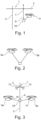
- Fig. 1:
- eine schematische Seitenansicht eines Krans in Form eines Turmdrehkrans mit einer am Lasthaken angeschlagenen Last sowie einer zusätzlichen, mit der Last verbundenen Flugdrohne, eines nicht erfindungsgemäßen Beispiels,
- Fig. 2:
- eine schematische Darstellung zweier zusammengespannter, mit einer gemeinsamen Last verbundenen Flugdrohnen,
- Fig. 3:
- eine Frontalansicht des Krans aus
Fig. 1 in einer Blickrichtung parallel zur Auslegerlängsachse, wobei zwei auf gegenüberliegenden Seiten des Lasthakens positionierte Flugdrohnen dargestellt sind, die mit der am Lasthaken angeschlagenen Last verbunden sind, - Fig. 4:
- eine schematische Darstellung der gemeinsamen Steuereinrichtung zum Steuern eines Krans und der zusätzlichen Flugdrohnen zum gemeinsamen Heben einer Last, eines nicht erfindungsgemäßen Beispiels,
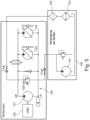
- Fig. 5:
- eine schematische Darstellung des hydraulischen Antriebsstrangs einer Flugdrohne nach der Erfindung, wobei weiterhin eine Versorgungsstation, an die die Flugdrohne mit dem hydrostatischen Antriebsstrang ankoppelbar ist, dargestellt ist, mittels derer der hydrostatische Antriebsstrang vorgespannt, gekühlt und filtriert werden kann,
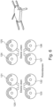
- Fig. 6:
- eine schematische Darstellung der auf zwei Ebenen verteilten, insgesamt acht Rotoren einer Flugdrohne, die ebenenweise und in einer Ebene seitenweise unterschiedliche Drehrichtungen realisieren, und
- Fig. 7:
- eine schematische Darstellung der Steuerungshierarchie zum Steuern einer Flugdrohne.
- Fig. 1:
- a schematic side view of a crane in the form of a tower crane with a load attached to the load hook and an additional aerial drone connected to the load, an example not according to the invention,
- Fig. 2:
- a schematic representation of two flying drones clamped together and connected to a common load,
- Fig. 3:
- a frontal view of the crane
Fig. 1 in a viewing direction parallel to the longitudinal axis of the boom, with two flying drones positioned on opposite sides of the load hook being shown, which are connected to the load attached to the load hook, - Fig. 4:
- a schematic representation of the common control device for controlling a crane and the additional flying drones for lifting a load together, an example not according to the invention,
- Fig. 5:
- a schematic representation of the hydraulic drive train of an aircraft drone according to the invention, further showing a supply station to which the aircraft drone can be coupled with the hydrostatic drive train, by means of which the hydrostatic drive train can be preloaded, cooled and filtered,
- Fig. 6:
- a schematic representation of the total of eight rotors of a flying drone, distributed over two levels, which realize different directions of rotation on each level and on one level, and
- Fig. 7:
- a schematic representation of the control hierarchy for controlling a flying drone.
Wie
Um den Lasthaken 8, der mit einem von der Laufkatze 4 ablaufenden Hubseil 7 verbunden sein kann, oder eine daran aufgenommene Last 20 im Zusammenspiel mit dem Lasthaken 8 manipulieren zu können, ist zumindest eine Flugdrohne 9 vorgesehen, die mit der Last 20 und/oder mit dem Lasthaken 8 durch ein Zug- und/oder Schubmittel, insbesondere ein Hubseil oder eine Schubstange, verbunden wird.In order to be able to manipulate the
Um zusätzlich zum Manipulieren der Last einen besseren Überblick über die Manipulationsaufgabe zu geben, kann an der Flugdrohne zumindest eine Kamera montiert ist, mittels derer ein Kamerabild vom Lasthaken 8 und/oder der Lasthakenumgebung bereitgestellt werden kann. Das genannte Kamerabild ist vorteilhafterweise ein Live- oder Echtzeitbild im Sinne eines Fernseh- oder Videobilds und wird von der Kamera 10 der Flugdrohne 9 drahtlos zu einer Anzeigeeinheit und/oder der Steuervorrichtung 5 des Krans 1 übertragen, wobei die genannte Anzeigeeinheit beispielsweise ein Maschinenführerdisplay nach Art eines Tablets oder eines Bildschirms oder eines Monitors sein kann, der in der Kranführerkabine 6 montiert sein kann. Wird in der zuvor genannten Weise ein Fernsteuerstand oder eine mobile Bedieneinheit zum Steuern des Krans 1 verwendet, kann die genannte Anzeigeeinheit 11 in dem Fernsteuerstand oder an der mobilen Bedieneinheit vorgesehen sein.In order to provide a better overview of the manipulation task in addition to manipulating the load, at least one camera can be mounted on the flying drone, by means of which a camera image of the
Die Flugdrohne 9 ist mit einer Fernsteuereinrichtung 12 versehen, die es erlaubt, die Flugdrohne 9 fernzusteuern, insbesondere die Flugsteueraggregate wie beispielsweise Rotorblätter anzusteuern, um die Flugposition der Flugdrohne 9 fernzusteuern.The
Ein entsprechendes Fernsteuermodul ist vorteilhafterweise in die Steuereinrichtung 5 integriert und/oder kann in der Kranführerkabine 6 und/oder dem Fernsteuerstand oder der mobilen Bedieneinheit vorgesehen sein, beispielsweise mit entsprechenden Joysticks ausgestattet sein.A corresponding remote control module is advantageously integrated into the
Wie
Der besagte Flugcomputer 90 kann hierbei von einer an der Flugdrohne 9a; 9b vorgesehenen Sensorik 120 mit Sensorsignalen versorgt werden, die einen aktuellen Betriebszustand der Flugdrohne und/oder Bewegungsparameter angeben, beispielsweise ein Positionssignal wie beispielsweise eine GPS-Position, Luftdruck, Windgeschwindigkeit, Kompassdaten oder Ähnliches.
Anhand der Sensordaten der Sensorik 120 und/oder anhand der von der Bodenstation 110 erhaltenen Daten kann der Flugcomputer 90 eine Flugregelung und/oder -steuerung ausführen bzw. abarbeiten und Antriebe der Flugdrohne ansteuern, insbesondere um eine Drehzahl und/oder ein Drehmoment eines jeweiligen Rotors zu variieren.Based on the sensor data from the
Wie
Bei einem solchen Multikopter kann die Flugbewegung und/oder die bereitgestellte Traglast bzw. Hub- und/oder Zuglast gezielt durch die Schubverteilung an den Rotoren gesteuert werden, insbesondere indem die Drehzahlen an den einzelnen Rotoren 120 bis 126 und/oder deren Drehmoment individuell, paarweise oder gruppenweise variiert wird, um ein Steigen und/oder Sinken der Flugdrohne 9a, 9b und/oder ein Nicken und/oder Rollen und/oder Gieren herbeizuführen.In such a multicopter, the flight movement and/or the provided load capacity or lifting and/or pulling load can be specifically controlled by the thrust distribution on the rotors, in particular by the speeds on the
Wie
Der hydrostatische Antriebsstrang 130 umfasst weiterhin mehrere weitere Hydrostaten 133 und 134, die jeweils mit einem der Rotoren 120 bis 127 antriebsverbunden sind und von dem als Pumpe arbeitenden Hydrostaten 131 her versorgt werden können. In der
Erfindungsgemäß sind die genannten Hydrostaten 131, 133 und 134 jeweils als verstellbare Hydrostaten ausgebildet, deren Schluckvolumen bzw. Pumpleistung variiert werden können. Beispielsweise können Schrägscheibenaggregate Verwendung finden, die im Verstellwinkel einstellbar ausgebildet sind.According to the invention, the
Um das Drehmoment und/oder die Drehzahl des jeweiligen Rotors 120 bis 127 zu steuern und/oder zu regeln, kann insbesondere folgendermaßen vorgegangen werden: Vorteilhafter Weise kann der Antriebsmotor 132 zumindest näherungsweise konstant betrieben werden, beispielsweise unter Volllast oder zumindest näherungsweise unter Volllast oder in einem hinsichtlich des Wirkungsgrades günstigen Betriebsbereich. Der von dem Verbrennungsmotor 132 angetriebene Hydrostat 131 setzt die rotatorische Antriebsbewegung des Antriebsmotors 132 in Hydraulikdruck um, der die weiteren Hydrostaten 133, 134 versorgt. Durch Verstellen der genannten Hydrostaten 133 und 134 kann das Drehmoment und/oder die Drehzahl der damit antriebsverbundenen Rotoren variiert werden. Zusätzlich können weitere hydraulischeIn order to control and/or regulate the torque and/or the speed of the
Stellglieder im hydrostatischen Antriebsstrang Verwendung finden, um die Rotoren zu steuern, beispielsweise über Drucksteuerventile, Massenstromdrosseln etcetera.Actuators are used in the hydrostatic drive train to control the rotors, for example via pressure control valves, mass flow throttles, etcetera.
Wie
Alternativ oder zusätzlich kann die Versorgungsstation eine Filtriereinrichtung 142 und/oder eine Kühlvorrichtung 143 umfassen, die ebenfalls mit dem hydrostatischen Antriebsstrang verbindbar ist/sind, um das Hydrauliköl zu filtrieren und/oder zu kühlen, wenn die Flugdrohne an die Versorgungsstation 140 angekoppelt ist.Alternatively or additionally, the supply station may include a
Um eine einfache Bedienung zu ermöglichen, kann die gemeinsame Steuereinrichtung 5 eine Hauptsteuereinrichtung 5a mit Eingabemitteln 19 zum Eingeben von Flug- und/oder Kranbewegungswünschen, von der aus auf Basis der eingegebenen Bewegungswünsche Steuersignale an die zumindest eine Flugdrohne 9a und/oder den Kran 1 generiert und übermittelt werden, und eine Zusatzsteuereinrichtung 5b aufweisen, von der aus Steuerbefehle für die zumindest eine und/oder die weitere Flugdrohne 9a; 9b in Abhängigkeit der Flug- oder Kranbewegungen, die von der Hauptsteuereinrichtung 5a veranlasst wurden, generiert und übermittelt werden.In order to enable simple operation, the
Vorteilhafterweise kann die Position der Flugdrohne 9 relativ zum Kran 1 und/oder dessen Lasthaken zumindest in einem autonomen Steuerungsmodus weitgehend autonom und unabhängig vom Kran gesteuert werden, beispielsweise in an sich bekannter Weise über die genannten Joysticks der Fernsteuereinrichtung 12. Über das autonome Steuerungsmodul der Positionssteuervorrichtung 13 kann eine Wunschposition der Flugdrohne 9 relativ zum Lasthaken 8 angeflogen werden.Advantageously, the position of the flying
Zusätzlich zu einem solchen autonomen Positionssteuermodul kann die gemeinsame Steervorrichtung 5 bzw. deren Zusatzsteuereinrichtung 5b, insbesondere deren Positionssteuervorrichtung 13 ein automatisches Folgesteuerungsmodul aufweisen, um eine vorbestimmte Position der Flugdrohne 9 - beispielsweise die durch das autonome Positionssteuermodul willkürlich angeflogene Wunschposition und/oder eine vorbestimmte, vorprogrammierte Position - zu halten, auch wenn der Kran 1 Kranbewegungen ausführt und/oder der Lasthaken 8 bewegt wird, so dass die Flugdrohne 9 dem Lasthaken 8 weitgehend automatisch folgt und die vorbestimmte Relativposition hierzu hält.In addition to such an autonomous position control module, the
Vorteilhafterweise ist eine Positionsbestimmungseinrichtung 18 vorgesehen, die automatisch kontinuierlich oder zyklisch die Position der Flugdrohne 9 relativ zu dem Kran 1 und/oder dessen Lasthaken 8 bestimmt, so dass die Positionssteuervorrichtung 13 in Abhängigkeit der bestimmten Relativposition die Flugdrohne 9 ansteuern kann.A
Die Flugdrohne 9 kann hierzu beispielsweise eine GPS-Einheit 14 umfassen, mittels derer die absolute Raumposition der Flugdrohne 9 bestimmt und der Positionssteuervorrichtung 13 übermittelt wird. Andererseits kann die Position des Lasthakens 8 bestimmt werden, so dass die Positionssteuervorrichtung 13 die Flugdrohne 9 fernsteuern kann, um die Relativposition zu halten.For this purpose, the
Die Lasthakenposition kann hierbei grundsätzlich ebenfalls per GPS bestimmt werden, beispielsweise indem in den Lasthaken eine GPS-Einheit integriert wird. Alternativ oder zusätzlich kann jedoch die Lasthakenposition auch aus der Stellung der Krankomponenten bestimmt, insbesondere von der Steuervorrichtung 5 des Krans berechnet werden, beispielsweise indem der Drehwinkel des Auslegers, die Position der Laufkatze 4 am Ausleger 3 und die Abspullänge des Hubseils 7 erfasst werden, woraus sich bei bekanntem Aufstellort des Krans 1 die Lasthakenposition zumindest näherungsweise bestimmen lässt, wenn man dynamische Pendelbewegungen oder Windeinflüsse vernachlässigt.The load hook position can in principle also be determined using GPS, for example by integrating a GPS unit into the load hook. Alternatively or additionally, however, the load hook position can also be determined from the position of the crane components, in particular calculated by the
Alternativ oder zusätzlich zu einer solchen absoluten Positionsbestimmung kann die Position der Flugdrohne 9 auch relativ in einem kranfesten, d.h. sich mit dem Kran mitdrehenden Koordinatensystem bestimmt werden. Hierzu können an dem Kran 1, beispielsweise an dessen Ausleger 3 und dessen Turm 2, ggf. auch an dessen Laufkatze 4 und/oder dessen Lasthaken 8 Sende-/Empfangseinheiten beispielsweise in Form von Transpondereinheiten 15 vorgesehen sein, die vorteilhafterweise an mehreren, voneinander beabstandeten Stellen am Kran 1 angebracht sind. Die genannten Sende-/Empfangseinheiten 15 können mit einer entsprechenden Sende-/Empfangseinheit 16 an der Flugdrohne 9 kommunizieren. Beispielsweise kann dann von einer Ortungseinrichtung 17, die in die Steuervorrichtung 5 des Krans 1 integriert sein kann, aus den Signallaufzeiten eines Signals zwischen der Sende-/Empfangseinheit 16 an der Flugdrohne 9 und den jeweiligen Sende-/Empfangseinheiten 15 am Kran 1 die Abstände der Flugdrohne 9 von den jeweiligen Sende-/Empfangseinheiten 15 am Kran 1 und hieraus die Position der Flugdrohne 9 relativ zum Kran 1 bestimmt werden.Alternatively or in addition to such an absolute position determination, the position of the
Zusätzlich zu der genannten Positionssteuerung kann die gemeinsame Steuereinrichtung 5 auch ein Hub- und/oder Zugkraft-Steuermodul umfassen, mittels dessen bestimmte Betriebparameter der Flugdrohne 9a bzw. 9b wie bspw. Rotordrehzal und/oder -anstellwinkel so gesteuert werden, dass das Lastaufnahmemittel an der Flugdrohne, bspw. ein Hubseil, das die Drohne mit der Last 20 oder dem Lasthaken 8 verbindet, mit einer gewünschten Kraft beaufschlagt wird, insbesondere mit einem bestimmten Kraftbetrag und/oder einer bestimmten Kraftrichtung beaufschlagt wird.In addition to the position control mentioned, the
Beispielsweise kann die Zugspannung und/oder die Neigung ϕ des genannten Hubseils, das die Drohne 9 mit der Last 20 verbindet, gegenüber der Horizontalen mittels einer geeigneten Sensorik überwacht und in Abhängigkeit hiervon die Flugdrohne angesteuert werden, um die Last 20 mittels der Drohne 9 in eine bestimmte Richtung mit einer bestimmten Stärke bzw. Kraft zu ziehen.For example, the tensile stress and/or the inclination ϕ of the mentioned hoist rope, which connects the
Wie
Neben der genannten Anbindung zumindest einer Flugdrohne 9 an einen Kran 1 kann es für bestimmte Hubaufgaben auch vorteilhaft sein, erfindungsgemäß nur mehrere Flugdrohnen 9a und 9b zusammenzuspannen und die entsprechende Last mit mehreren Flugdrohnen, jedoch ohne den Kran bzw. dessen Lasthaken zu heben, wie dies bspw.
Werden mehrere Flugdrohnen 9a, b zusammengespannt und ohne Kran zum Heben einer Last 20 eingesetzt, kann die gemeisame Steuereinrichtung 5 die beiden Flugdrohnen 9a und 9b auf Abstand voneinander halten und gemeinsam entlang einer bestimmten Flugbahn zu einem Bestimmungsziel fliegen. Die Flugdrohnen 9 a, b können dabei beispielsweise über separate Hubseile an der gemeinsamen Last befestigt werden, oder auch an einem gemeinsamen Hubjoch befestigt werden, an dem wiederum die Last 20 befestigt ist.If several flying
Claims (15)
- Method for lifting a load (20), in which at least one aerial drone (9) carries at least a portion of the load (20) and the load (20) is connected to a further aerial drone (9b) and is partially carried and/or directed by the further aerial drone (9b), wherein the two aerial drones (9a, b) are controlled in coordination with each other by a common controller (5) for controlling flight movements, characterised in that a lifting and/or tensile force and/or a flight trajectory of the aerial drones (9a; 9b) is controlled by varying a rotor speed and/or a rotor torque, wherein the aerial drones (9a; 9b) each have a hydrostatic drive train (130) for driving at least one rotor (120-127) comprising at least one hydrostatic device (131) that operates as a pump and can be driven by a drive motor (132), and each have at least one further hydrostatic device (133, 134) that operates as a motor and can be connected to the rotor, and said rotor speed and/or rotor torque is controlled by adjusting a hydrostatic displacement volume and/or a hydrostatic swivel angle and/or a hydrostatic pumping capacity.
- Method according to the preceding claim, wherein the load (20) is additionally connected to a load hook (8) of a crane and is partially carried and directed by the crane (1), wherein the aerial drones together with the crane (1) are controlled in a coordinated manner by a common controller (5).
- Method according to any one of the preceding claims, wherein the common controller (5) has a main controller (5a) having input means (19) for inputting desired flight and/or crane movements, from which control signals are generated and transmitted to the at least one aerial drone (9a) and/or the crane (1) on the basis of the input desired movements, and has an additional controller (5b), from which control commands for the at least one and/or the further aerial drone (9a; 9b) are generated and transmitted depending on the flight or crane movements initiated by the main controller (5a).
- Method according to any one of the preceding claims, wherein the drive motor (132) is designed as an internal combustion engine and is operated in an at least approximately constant operating state, in particular at least approximately in the full load range, wherein speed changes and/or torque changes on the rotor are controlled in a variable manner by adjusting the at least one hydrostatic device (133, 134; 131).
- Method according to any one of the preceding claims, wherein the aerial drones (9a; 9b) are controlled such that a force (F) having a horizontal component (FH) is exerted on the load (20), wherein the aerial drones (9) are controlled such that the horizontal component (FH) counteracts a pendulum motion of the load (20) and/or counteracts a wind force.
- Method according to any one of the preceding claims, wherein the aerial drones (9) are controlled such that the load (20) is rotated about a vertical axis while being lifted, wherein at least one aerial drone (9) is flown through the load (20) along an at least approximately helical path about a vertical axis when lifting the load (20).
- Method according to any one of the preceding claims, wherein the aerial drones (9) are autonomously remotely controlled in an autonomous control mode, such that an aerial drone (9) approaches various predefinable positions relative to a guide drone (9a).
- Method according to any one of the preceding claims, wherein specified operating parameters of each aerial drone (9), in particular rotor speed and/or rotor angle of attack, are controlled by the controller (5) such that a load suspension means on each aerial drone (9) connecting the aerial drone (9) to the load (20) is subjected to a specified force magnitude and/or a specified force direction, wherein the force directions of the different aerial drones point in different directions.
- Device for lifting a load (20), in which at least one aerial drone (9) is connected to the load (20) by a load suspension means for carrying at least a portion of the load (20) and the load (20) is connected to a further aerial drone (9b), wherein a common controller (5) is provided for controlling the two aerial drones (9a, b) in coordination with each other, characterised in that a lifting and/or tensile force and/or a flight trajectory of the aerial drones (9a; 9b) can be controlled by varying a rotor speed and/or a rotor torque, wherein the aerial drones (9a; 9b) each have a hydrostatic drive train (130) for driving at least one rotor (120-127) comprising at least one hydrostatic device (131) that operates as a pump and can be driven by a drive motor (132), and each have at least one further hydrostatic device (133, 134) that operates as a motor and can be connected to the rotor, and said rotor speed and/or rotor torque can be controlled by adjusting a hydrostatic displacement volume and/or a hydrostatic swivel angle and/or a hydrostatic pumping capacity.
- Device according to the preceding claim, wherein the load (20) is additionally connected to a load hook (8) of a crane (1) and the common controller (5) is designed to control the two aerial drones together with the crane (1) in a coordinated manner.
- Device according to any one of the two preceding claims, wherein the common controller (5) has a main controller (5a) having input means (19) for inputting desired flight and/or crane movements, from which control signals are generated and transmitted to the at least one aerial drone (9a) and/or the crane (1) on the basis of the input desired movements, and has an additional controller (5b),which is configured to generate control commands for the at least one and/or the further aerial drone (9a; 9b) depending on the flight or crane movements initiated by the main controller (5a).
- Device according to any one of the preceding claims 9 to 11, wherein the controller (5) has a position control device (13), which has an automatic follow-up control module for controlling the aerial drone (9) depending on a guide drone position in such a way that the aerial drone (9) automatically follows guide drone movements and maintains a desired position relative to the guidance drone even during guide drone movements, wherein the controller (5) is configured to control the aerial drones (9) such that one of the aerial drones (9) flies along a helical path about a vertical axis passing through the load (20) when lifting the load (20).
- Device according to claim 10 or any one of claim 11 and 12 referring back to it, wherein a/the position control device (13) has an autonomous control module for autonomous remote control of the aerial drone (9) such that the aerial drone (9) approaches various desired positions relative to the crane and/or a load hook of the crane.
- Device according to claim 10 or any one of claim 11-13 referring back to it, wherein a position determiner (18) for determining the position of the aerial drone (9) relative to a guide drone is provided, wherein a/the position control device (13) is deigned to control the aerial device (9) depending on the automatically determined relative position, wherein the aerial drone (9) has a GPS unit for absolute position determination of the aerial drone (9), wherein the position control device (13) for controlling the position of the aerial drone (9) relative to the crane is designed to control the aerial drone (9) depending on the absolute position data of the aerial drone (9) and the absolute position data of the crane, wherein the position determiner (18) has a signal locating device for locating a signal output by the aerial drone (9), wherein said signal locating device has mutually spaced transceiver units (15) attached to the crane for communicating with a transceiver unit (16) on the aerial drone (9), and an evaluation unit for evaluating the transmitted signals between the transceiver units (15) on a crane side and the transceiver unit (16) on a drone side, with respect to predetermined signal characteristics, in particular with respect to signal propagation time and/or signal strength, and for determining the position of the aerial drone (9) relative to the crane (1) from the signal characteristics.
- Device according to any one of the preceding claims 9 to 14, wherein an internal combustion engine (VKM) is provided as a drive motor (132), wherein the aerial drone (9) is designed as a multicopter and has a plurality of rotors, wherein the hydrostatic drive train (130) comprises a plurality of hydrostatic devices (133, 134) operating as motors, which are each drivingly connected to a respective rotor, and are individually adjustable to individually control the speed of the rotors connected to the respective hydrostatic devices.
Applications Claiming Priority (3)
| Application Number | Priority Date | Filing Date | Title |
|---|---|---|---|
| DE102017112765.8A DE102017112765A1 (en) | 2017-06-09 | 2017-06-09 | Method and device for lifting a load |
| PCT/EP2018/065182 WO2018224657A1 (en) | 2017-06-09 | 2018-06-08 | Method and device for lifting a load |
| EP18730740.0A EP3619111B1 (en) | 2017-06-09 | 2018-06-08 | Method and device for lifting a load |
Related Parent Applications (2)
| Application Number | Title | Priority Date | Filing Date |
|---|---|---|---|
| EP18730740.0A Division EP3619111B1 (en) | 2017-06-09 | 2018-06-08 | Method and device for lifting a load |
| EP18730740.0A Division-Into EP3619111B1 (en) | 2017-06-09 | 2018-06-08 | Method and device for lifting a load |
Publications (2)
| Publication Number | Publication Date |
|---|---|
| EP3733512A1 EP3733512A1 (en) | 2020-11-04 |
| EP3733512B1 true EP3733512B1 (en) | 2023-10-18 |
Family
ID=62597497
Family Applications (2)
| Application Number | Title | Priority Date | Filing Date |
|---|---|---|---|
| EP18730740.0A Active EP3619111B1 (en) | 2017-06-09 | 2018-06-08 | Method and device for lifting a load |
| EP20182196.4A Active EP3733512B1 (en) | 2017-06-09 | 2018-06-08 | Method and device for lifting a load |
Family Applications Before (1)
| Application Number | Title | Priority Date | Filing Date |
|---|---|---|---|
| EP18730740.0A Active EP3619111B1 (en) | 2017-06-09 | 2018-06-08 | Method and device for lifting a load |
Country Status (9)
| Country | Link |
|---|---|
| US (1) | US11981433B2 (en) |
| EP (2) | EP3619111B1 (en) |
| CN (1) | CN110914152B (en) |
| AU (1) | AU2018280853B2 (en) |
| BR (1) | BR112019025789A2 (en) |
| DE (1) | DE102017112765A1 (en) |
| ES (1) | ES2965874T3 (en) |
| RU (1) | RU2768693C2 (en) |
| WO (1) | WO2018224657A1 (en) |
Families Citing this family (30)
| Publication number | Priority date | Publication date | Assignee | Title |
|---|---|---|---|---|
| DE102017112765A1 (en) | 2017-06-09 | 2018-12-13 | Liebherr-Werk Biberach Gmbh | Method and device for lifting a load |
| US11391267B2 (en) * | 2017-06-30 | 2022-07-19 | Vestas Wind Systems A/S | System and method for handling wind turbine components for assembly thereof |
| US10906783B2 (en) * | 2017-08-25 | 2021-02-02 | Columbia Helicopters, Inc. | Load placement system |
| US11142316B2 (en) * | 2018-02-08 | 2021-10-12 | Vita Inclinata Technologies, Inc. | Control of drone-load system method, system, and apparatus |
| US12434813B2 (en) | 2018-02-08 | 2025-10-07 | Vita Inclinata Ip Holdings Llc | Bidirectional thrust apparatus, system and method |
| US12304779B2 (en) | 2018-02-08 | 2025-05-20 | Vita Inclinata Ip Holdings Llc | On-board power and remote power for suspended load control apparatuses, systems, and methods |
| US11142433B2 (en) | 2018-02-08 | 2021-10-12 | Vita Inclinata Technologies, Inc. | Bidirectional thrust apparatus, system, and method |
| US11945697B2 (en) | 2018-02-08 | 2024-04-02 | Vita Inclinata Ip Holdings Llc | Multiple remote control for suspended load control equipment apparatus, system, and method |
| WO2021194628A2 (en) * | 2020-01-28 | 2021-09-30 | Vita Inclinata Technologies, Inc. | Control of drone-load system method, system, and apparatus |
| US12246952B2 (en) | 2018-02-08 | 2025-03-11 | Vita Inclintata IP Holdings LLC | Hoist and deployable equipment apparatus, system, and method |
| US11209836B1 (en) | 2018-02-08 | 2021-12-28 | Vita Inclinata Technologies, Inc. | Long line loiter apparatus, system, and method |
| US11964849B2 (en) * | 2018-03-02 | 2024-04-23 | Vestas Wind Systems A/S | System and method for handling wind turbine components for assembly thereof |
| WO2020176665A1 (en) | 2019-02-26 | 2020-09-03 | Vita Inclinata Technologies, Inc. | Cable deployment apparatus, system, and methods for suspended load control equipment |
| US11618566B1 (en) | 2019-04-12 | 2023-04-04 | Vita Inclinata Technologies, Inc. | State information and telemetry for suspended load control equipment apparatus, system, and method |
| US11834305B1 (en) | 2019-04-12 | 2023-12-05 | Vita Inclinata Ip Holdings Llc | Apparatus, system, and method to control torque or lateral thrust applied to a load suspended on a suspension cable |
| CN113226927B (en) * | 2019-11-15 | 2024-10-29 | 乐天集团股份有限公司 | Unmanned aerial vehicle system, control device and control method |
| CA3159310A1 (en) | 2019-11-25 | 2021-06-03 | Derek SIKORA | Coupling for suspended load control apparatus, system, and method |
| US12216480B2 (en) * | 2020-05-01 | 2025-02-04 | United States Of America, As Represented By The Secretary Of The Army | Aircraft multi-lift system with synchronized maneuvering and load feedback control |
| CN111927099B (en) * | 2020-09-03 | 2020-12-25 | 上海建工集团股份有限公司 | Full-size 3D printing system and method |
| IT202100000788A1 (en) | 2021-01-18 | 2022-07-18 | E80 Group S P A | APPARATUS AND METHOD FOR THE HANDLING OF OBJECTS |
| JP7621160B2 (en) * | 2021-03-31 | 2025-01-24 | 住友重機械建機クレーン株式会社 | Display device and route display program |
| US12448952B2 (en) * | 2021-07-09 | 2025-10-21 | Vestas Wind Systems A/S | System and method for repairing leading edge damage on a wind turbine blade |
| CN113946158A (en) * | 2021-12-02 | 2022-01-18 | 中国地质调查局地球物理调查中心 | Earthquake wave excitation system and method based on unmanned aerial vehicle set throwing in earthquake source body |
| JP7682112B2 (en) * | 2022-01-04 | 2025-05-23 | 西松建設株式会社 | Imaging equipment and monitoring system |
| WO2023211499A1 (en) | 2022-04-29 | 2023-11-02 | Vita Inclinata Ip Holdings Llc | Machine learning real property object detection and analysis apparatus, system, and method |
| EP4532331A1 (en) * | 2022-05-27 | 2025-04-09 | Singapore University of Technology and Design | Multi-monocopter system and method of operating therof |
| RU2798089C1 (en) * | 2022-12-28 | 2023-06-15 | Павел Русланович Андреев | Aircraft (variants), self-propelled module, payload, system and method for moving the payload (variants) |
| US11992444B1 (en) | 2023-12-04 | 2024-05-28 | Vita Inclinata Ip Holdings Llc | Apparatus, system, and method to control torque or lateral thrust applied to a load suspended on a suspension cable |
| CN117692358B (en) * | 2023-12-12 | 2024-07-05 | 国网内蒙古东部电力有限公司呼伦贝尔供电公司 | A real-time reliability status detection and alarm system based on UAV mounting |
| US20260042643A1 (en) * | 2024-08-12 | 2026-02-12 | International Business Machines Corporation | Mitigating oscillation of a lift cable on a crane |
Family Cites Families (26)
| Publication number | Priority date | Publication date | Assignee | Title |
|---|---|---|---|---|
| US3799358A (en) * | 1972-06-12 | 1974-03-26 | Zachry Co H B | Helicopter tail rotor device |
| SU1763292A1 (en) * | 1990-11-13 | 1992-09-23 | Научно-производственное объединение применения гражданской авиации в народном хозяйстве | Piloting technique in assembling load with helicopters |
| JPH05193584A (en) * | 1992-01-17 | 1993-08-03 | Mitsubishi Heavy Ind Ltd | Attitude stabilizing device for suspended load |
| JPH0710464A (en) * | 1993-06-24 | 1995-01-13 | Hitachi Constr Mach Co Ltd | Positioning device for suspended loads |
| US8157205B2 (en) * | 2006-03-04 | 2012-04-17 | Mcwhirk Bruce Kimberly | Multibody aircrane |
| JP5018256B2 (en) * | 2007-06-08 | 2012-09-05 | コベルコクレーン株式会社 | Crane working vehicle |
| CA2666889A1 (en) * | 2008-05-27 | 2009-11-27 | Wilfred P. So | System and method for multiple aircraft lifting a common payload |
| EP2172412A1 (en) * | 2008-10-06 | 2010-04-07 | Regione Autonoma Valle d'Aosta Direzione Protezione Civile | Stretcher stabilizing device |
| JP5303798B2 (en) * | 2010-07-16 | 2013-10-02 | 株式会社小松製作所 | Unmanned vehicle traveling system and traveling control method thereof |
| RU2449924C1 (en) * | 2010-11-15 | 2012-05-10 | Открытое акционерное общество "Московский вертолетный завод им.М.Л. Миля" | Heavy freight air transportation system |
| DE112012000169T5 (en) * | 2011-07-05 | 2013-07-18 | Trimble Navigation Limited | Crane maneuver support |
| US8591161B1 (en) * | 2011-10-04 | 2013-11-26 | The Boeing Company | Maneuvering autonomous rotorcraft cargo attachment system with motion compensation |
| FI126364B (en) * | 2012-05-25 | 2016-10-31 | Konecranes Global Oy | Determination of the path of movement of a lifting device |
| US9079662B1 (en) * | 2012-10-01 | 2015-07-14 | The Boeing Company | Co-operative, modular, unmanned, vertical lift cargo vehicles |
| US10273004B2 (en) * | 2013-06-13 | 2019-04-30 | The Boeing Company | Systems and methods for moving a load using unmanned vehicles |
| US9205922B1 (en) * | 2013-07-17 | 2015-12-08 | The Boeing Company | Systems and methods for implementing a payload distribution system |
| US9073624B2 (en) * | 2013-12-09 | 2015-07-07 | The Boeing Company | Methods and apparatus to cooperatively lift a payload |
| US9555899B2 (en) * | 2014-03-27 | 2017-01-31 | The United States Of America As Represented By The Secretary Of The Navy | Mobile arresting system |
| US9146557B1 (en) * | 2014-04-23 | 2015-09-29 | King Fahd University Of Petroleum And Minerals | Adaptive control method for unmanned vehicle with slung load |
| WO2016068767A1 (en) * | 2014-10-30 | 2016-05-06 | Acc Innovation Ab | Multi-rotor aerial vehicle |
| US9944366B2 (en) * | 2015-05-19 | 2018-04-17 | Rujing Tang | Unmanned aerial vehicle system and methods for use |
| DE102015119279A1 (en) * | 2015-11-09 | 2017-05-11 | Antony Pfoertzsch | Unmanned flying object and control and remote control therefor and method for controlling an unmanned flying object |
| DE102016000353A1 (en) * | 2016-01-14 | 2017-07-20 | Liebherr-Components Biberach Gmbh | Crane, construction machine or industrial truck simulator |
| US10457393B2 (en) * | 2016-04-05 | 2019-10-29 | Walmart Apollo, Llc | Apparatuses and methods for receiving aerial vehicle delivery |
| DE102017112765A1 (en) | 2017-06-09 | 2018-12-13 | Liebherr-Werk Biberach Gmbh | Method and device for lifting a load |
| US11964849B2 (en) * | 2018-03-02 | 2024-04-23 | Vestas Wind Systems A/S | System and method for handling wind turbine components for assembly thereof |
-
2017
- 2017-06-09 DE DE102017112765.8A patent/DE102017112765A1/en not_active Withdrawn
-
2018
- 2018-06-08 BR BR112019025789-6A patent/BR112019025789A2/en not_active Application Discontinuation
- 2018-06-08 ES ES18730740T patent/ES2965874T3/en active Active
- 2018-06-08 WO PCT/EP2018/065182 patent/WO2018224657A1/en not_active Ceased
- 2018-06-08 CN CN201880038216.3A patent/CN110914152B/en active Active
- 2018-06-08 AU AU2018280853A patent/AU2018280853B2/en active Active
- 2018-06-08 EP EP18730740.0A patent/EP3619111B1/en active Active
- 2018-06-08 EP EP20182196.4A patent/EP3733512B1/en active Active
- 2018-06-08 RU RU2019143683A patent/RU2768693C2/en active
-
2019
- 2019-12-09 US US16/708,266 patent/US11981433B2/en active Active
Also Published As
| Publication number | Publication date |
|---|---|
| BR112019025789A2 (en) | 2020-07-07 |
| AU2018280853A1 (en) | 2020-01-16 |
| RU2019143683A3 (en) | 2021-10-12 |
| EP3619111A1 (en) | 2020-03-11 |
| CN110914152A (en) | 2020-03-24 |
| DE102017112765A1 (en) | 2018-12-13 |
| AU2018280853B2 (en) | 2024-02-29 |
| EP3733512A1 (en) | 2020-11-04 |
| RU2768693C2 (en) | 2022-03-24 |
| US11981433B2 (en) | 2024-05-14 |
| US20200180763A1 (en) | 2020-06-11 |
| ES2965874T3 (en) | 2024-04-17 |
| RU2019143683A (en) | 2021-07-09 |
| EP3619111B1 (en) | 2023-09-27 |
| CN110914152B (en) | 2024-04-23 |
| WO2018224657A1 (en) | 2018-12-13 |
Similar Documents
| Publication | Publication Date | Title |
|---|---|---|
| EP3733512B1 (en) | Method and device for lifting a load | |
| EP3411534B1 (en) | Method and device for controlling a crane, a bagger, a crawler, or a similar construction machine | |
| EP1444162B1 (en) | Mobile crane having a superlift device | |
| DE102014015335B4 (en) | Generative manufacturing device and manufacturing process for the layered construction of structures | |
| DE102019122796A1 (en) | Crane and method of controlling such a crane | |
| WO1995006178A1 (en) | Large manipulator, especially for self-propelled concrete pumps, and method for operating it | |
| EP2272785A1 (en) | Method for controlling a drive of a crane | |
| EP3953287B1 (en) | Apparatus for controlling a load suspended on a cord | |
| EP3297946B1 (en) | Mobile shaft winch | |
| AT520008A1 (en) | Method for damping torsional vibrations of a load-receiving element of a lifting device | |
| EP4402087A1 (en) | Crane | |
| DE102019121550A1 (en) | Transport unit and system for transporting an object | |
| DE202019000750U1 (en) | Self-propelled vehicle for moving plate transport racks | |
| EP3328781B1 (en) | Mobile shaft winch | |
| EP2789488A2 (en) | Drive system | |
| DE102018100133A1 (en) | Crane with anti-collision device and method for operating several such cranes | |
| DE4025749A1 (en) | METHOD FOR THE AUTOMATIC OPERATION OF A TURNING CRANE | |
| EP4211069A1 (en) | Tower crane, method and control unit for operating a tower crane, trolley and trolley travel unit | |
| DE4405525A1 (en) | Crane with drive for horizontal transfer of cable-suspended load | |
| EP0907604A1 (en) | Method and arrangement for preventing load swings with a suspended-load-moving apparatus performing rotational movements | |
| EP2897892B1 (en) | Method for operating a crane, and crane | |
| WO2022238228A1 (en) | Remote control system for a construction machine and method for controlling a construction machine | |
| DE8916221U1 (en) | Container crane system | |
| DE102024125332A1 (en) | Transporting a load using a paraglider | |
| WO2025252462A1 (en) | Transport of a load by means of a paraglider |
Legal Events
| Date | Code | Title | Description |
|---|---|---|---|
| PUAI | Public reference made under article 153(3) epc to a published international application that has entered the european phase |
Free format text: ORIGINAL CODE: 0009012 |
|
| STAA | Information on the status of an ep patent application or granted ep patent |
Free format text: STATUS: THE APPLICATION HAS BEEN PUBLISHED |
|
| AC | Divisional application: reference to earlier application |
Ref document number: 3619111 Country of ref document: EP Kind code of ref document: P |
|
| AK | Designated contracting states |
Kind code of ref document: A1 Designated state(s): AL AT BE BG CH CY CZ DE DK EE ES FI FR GB GR HR HU IE IS IT LI LT LU LV MC MK MT NL NO PL PT RO RS SE SI SK SM TR |
|
| AX | Request for extension of the european patent |
Extension state: BA ME |
|
| STAA | Information on the status of an ep patent application or granted ep patent |
Free format text: STATUS: REQUEST FOR EXAMINATION WAS MADE |
|
| 17P | Request for examination filed |
Effective date: 20210504 |
|
| RBV | Designated contracting states (corrected) |
Designated state(s): AL AT BE BG CH CY CZ DE DK EE ES FI FR GB GR HR HU IE IS IT LI LT LU LV MC MK MT NL NO PL PT RO RS SE SI SK SM TR |
|
| RIC1 | Information provided on ipc code assigned before grant |
Ipc: B64U 101/60 20230101ALN20230411BHEP Ipc: B64D 1/22 20060101ALI20230411BHEP Ipc: B66C 13/04 20060101ALI20230411BHEP Ipc: G05D 1/10 20060101ALI20230411BHEP Ipc: B64C 39/02 20060101AFI20230411BHEP |
|
| GRAP | Despatch of communication of intention to grant a patent |
Free format text: ORIGINAL CODE: EPIDOSNIGR1 |
|
| STAA | Information on the status of an ep patent application or granted ep patent |
Free format text: STATUS: GRANT OF PATENT IS INTENDED |
|
| RIC1 | Information provided on ipc code assigned before grant |
Ipc: B64U 101/60 20230101ALN20230508BHEP Ipc: B64D 1/22 20060101ALI20230508BHEP Ipc: B66C 13/04 20060101ALI20230508BHEP Ipc: G05D 1/10 20060101ALI20230508BHEP Ipc: B64C 39/02 20060101AFI20230508BHEP |
|
| INTG | Intention to grant announced |
Effective date: 20230524 |
|
| GRAS | Grant fee paid |
Free format text: ORIGINAL CODE: EPIDOSNIGR3 |
|
| GRAA | (expected) grant |
Free format text: ORIGINAL CODE: 0009210 |
|
| STAA | Information on the status of an ep patent application or granted ep patent |
Free format text: STATUS: THE PATENT HAS BEEN GRANTED |
|
| AC | Divisional application: reference to earlier application |
Ref document number: 3619111 Country of ref document: EP Kind code of ref document: P |
|
| AK | Designated contracting states |
Kind code of ref document: B1 Designated state(s): AL AT BE BG CH CY CZ DE DK EE ES FI FR GB GR HR HU IE IS IT LI LT LU LV MC MK MT NL NO PL PT RO RS SE SI SK SM TR |
|
| REG | Reference to a national code |
Ref country code: GB Ref legal event code: FG4D Free format text: NOT ENGLISH |
|
| REG | Reference to a national code |
Ref country code: CH Ref legal event code: EP |
|
| REG | Reference to a national code |
Ref country code: DE Ref legal event code: R096 Ref document number: 502018013493 Country of ref document: DE |
|
| REG | Reference to a national code |
Ref country code: IE Ref legal event code: FG4D Free format text: LANGUAGE OF EP DOCUMENT: GERMAN |
|
| P01 | Opt-out of the competence of the unified patent court (upc) registered |
Effective date: 20231012 |
|
| REG | Reference to a national code |
Ref country code: LT Ref legal event code: MG9D |
|
| REG | Reference to a national code |
Ref country code: NL Ref legal event code: MP Effective date: 20231018 |
|
| PG25 | Lapsed in a contracting state [announced via postgrant information from national office to epo] |
Ref country code: NL Free format text: LAPSE BECAUSE OF FAILURE TO SUBMIT A TRANSLATION OF THE DESCRIPTION OR TO PAY THE FEE WITHIN THE PRESCRIBED TIME-LIMIT Effective date: 20231018 |
|
| PG25 | Lapsed in a contracting state [announced via postgrant information from national office to epo] |
Ref country code: GR Free format text: LAPSE BECAUSE OF FAILURE TO SUBMIT A TRANSLATION OF THE DESCRIPTION OR TO PAY THE FEE WITHIN THE PRESCRIBED TIME-LIMIT Effective date: 20240119 |
|
| PG25 | Lapsed in a contracting state [announced via postgrant information from national office to epo] |
Ref country code: IS Free format text: LAPSE BECAUSE OF FAILURE TO SUBMIT A TRANSLATION OF THE DESCRIPTION OR TO PAY THE FEE WITHIN THE PRESCRIBED TIME-LIMIT Effective date: 20240218 |
|
| PG25 | Lapsed in a contracting state [announced via postgrant information from national office to epo] |
Ref country code: LT Free format text: LAPSE BECAUSE OF FAILURE TO SUBMIT A TRANSLATION OF THE DESCRIPTION OR TO PAY THE FEE WITHIN THE PRESCRIBED TIME-LIMIT Effective date: 20231018 |
|
| PG25 | Lapsed in a contracting state [announced via postgrant information from national office to epo] |
Ref country code: ES Free format text: LAPSE BECAUSE OF FAILURE TO SUBMIT A TRANSLATION OF THE DESCRIPTION OR TO PAY THE FEE WITHIN THE PRESCRIBED TIME-LIMIT Effective date: 20231018 |
|
| PG25 | Lapsed in a contracting state [announced via postgrant information from national office to epo] |
Ref country code: LT Free format text: LAPSE BECAUSE OF FAILURE TO SUBMIT A TRANSLATION OF THE DESCRIPTION OR TO PAY THE FEE WITHIN THE PRESCRIBED TIME-LIMIT Effective date: 20231018 Ref country code: IS Free format text: LAPSE BECAUSE OF FAILURE TO SUBMIT A TRANSLATION OF THE DESCRIPTION OR TO PAY THE FEE WITHIN THE PRESCRIBED TIME-LIMIT Effective date: 20240218 Ref country code: GR Free format text: LAPSE BECAUSE OF FAILURE TO SUBMIT A TRANSLATION OF THE DESCRIPTION OR TO PAY THE FEE WITHIN THE PRESCRIBED TIME-LIMIT Effective date: 20240119 Ref country code: ES Free format text: LAPSE BECAUSE OF FAILURE TO SUBMIT A TRANSLATION OF THE DESCRIPTION OR TO PAY THE FEE WITHIN THE PRESCRIBED TIME-LIMIT Effective date: 20231018 Ref country code: BG Free format text: LAPSE BECAUSE OF FAILURE TO SUBMIT A TRANSLATION OF THE DESCRIPTION OR TO PAY THE FEE WITHIN THE PRESCRIBED TIME-LIMIT Effective date: 20240118 Ref country code: PT Free format text: LAPSE BECAUSE OF FAILURE TO SUBMIT A TRANSLATION OF THE DESCRIPTION OR TO PAY THE FEE WITHIN THE PRESCRIBED TIME-LIMIT Effective date: 20240219 |
|
| PG25 | Lapsed in a contracting state [announced via postgrant information from national office to epo] |
Ref country code: SE Free format text: LAPSE BECAUSE OF FAILURE TO SUBMIT A TRANSLATION OF THE DESCRIPTION OR TO PAY THE FEE WITHIN THE PRESCRIBED TIME-LIMIT Effective date: 20231018 Ref country code: RS Free format text: LAPSE BECAUSE OF FAILURE TO SUBMIT A TRANSLATION OF THE DESCRIPTION OR TO PAY THE FEE WITHIN THE PRESCRIBED TIME-LIMIT Effective date: 20231018 Ref country code: PL Free format text: LAPSE BECAUSE OF FAILURE TO SUBMIT A TRANSLATION OF THE DESCRIPTION OR TO PAY THE FEE WITHIN THE PRESCRIBED TIME-LIMIT Effective date: 20231018 Ref country code: NO Free format text: LAPSE BECAUSE OF FAILURE TO SUBMIT A TRANSLATION OF THE DESCRIPTION OR TO PAY THE FEE WITHIN THE PRESCRIBED TIME-LIMIT Effective date: 20240118 Ref country code: LV Free format text: LAPSE BECAUSE OF FAILURE TO SUBMIT A TRANSLATION OF THE DESCRIPTION OR TO PAY THE FEE WITHIN THE PRESCRIBED TIME-LIMIT Effective date: 20231018 Ref country code: HR Free format text: LAPSE BECAUSE OF FAILURE TO SUBMIT A TRANSLATION OF THE DESCRIPTION OR TO PAY THE FEE WITHIN THE PRESCRIBED TIME-LIMIT Effective date: 20231018 |
|
| PG25 | Lapsed in a contracting state [announced via postgrant information from national office to epo] |
Ref country code: DK Free format text: LAPSE BECAUSE OF FAILURE TO SUBMIT A TRANSLATION OF THE DESCRIPTION OR TO PAY THE FEE WITHIN THE PRESCRIBED TIME-LIMIT Effective date: 20231018 |
|
| REG | Reference to a national code |
Ref country code: DE Ref legal event code: R097 Ref document number: 502018013493 Country of ref document: DE |
|
| PG25 | Lapsed in a contracting state [announced via postgrant information from national office to epo] |
Ref country code: CZ Free format text: LAPSE BECAUSE OF FAILURE TO SUBMIT A TRANSLATION OF THE DESCRIPTION OR TO PAY THE FEE WITHIN THE PRESCRIBED TIME-LIMIT Effective date: 20231018 |
|
| PG25 | Lapsed in a contracting state [announced via postgrant information from national office to epo] |
Ref country code: SK Free format text: LAPSE BECAUSE OF FAILURE TO SUBMIT A TRANSLATION OF THE DESCRIPTION OR TO PAY THE FEE WITHIN THE PRESCRIBED TIME-LIMIT Effective date: 20231018 |
|
| PG25 | Lapsed in a contracting state [announced via postgrant information from national office to epo] |
Ref country code: SM Free format text: LAPSE BECAUSE OF FAILURE TO SUBMIT A TRANSLATION OF THE DESCRIPTION OR TO PAY THE FEE WITHIN THE PRESCRIBED TIME-LIMIT Effective date: 20231018 Ref country code: SK Free format text: LAPSE BECAUSE OF FAILURE TO SUBMIT A TRANSLATION OF THE DESCRIPTION OR TO PAY THE FEE WITHIN THE PRESCRIBED TIME-LIMIT Effective date: 20231018 Ref country code: RO Free format text: LAPSE BECAUSE OF FAILURE TO SUBMIT A TRANSLATION OF THE DESCRIPTION OR TO PAY THE FEE WITHIN THE PRESCRIBED TIME-LIMIT Effective date: 20231018 Ref country code: IT Free format text: LAPSE BECAUSE OF FAILURE TO SUBMIT A TRANSLATION OF THE DESCRIPTION OR TO PAY THE FEE WITHIN THE PRESCRIBED TIME-LIMIT Effective date: 20231018 Ref country code: EE Free format text: LAPSE BECAUSE OF FAILURE TO SUBMIT A TRANSLATION OF THE DESCRIPTION OR TO PAY THE FEE WITHIN THE PRESCRIBED TIME-LIMIT Effective date: 20231018 Ref country code: DK Free format text: LAPSE BECAUSE OF FAILURE TO SUBMIT A TRANSLATION OF THE DESCRIPTION OR TO PAY THE FEE WITHIN THE PRESCRIBED TIME-LIMIT Effective date: 20231018 Ref country code: CZ Free format text: LAPSE BECAUSE OF FAILURE TO SUBMIT A TRANSLATION OF THE DESCRIPTION OR TO PAY THE FEE WITHIN THE PRESCRIBED TIME-LIMIT Effective date: 20231018 |
|
| PLBE | No opposition filed within time limit |
Free format text: ORIGINAL CODE: 0009261 |
|
| STAA | Information on the status of an ep patent application or granted ep patent |
Free format text: STATUS: NO OPPOSITION FILED WITHIN TIME LIMIT |
|
| 26N | No opposition filed |
Effective date: 20240719 |
|
| PG25 | Lapsed in a contracting state [announced via postgrant information from national office to epo] |
Ref country code: SI Free format text: LAPSE BECAUSE OF FAILURE TO SUBMIT A TRANSLATION OF THE DESCRIPTION OR TO PAY THE FEE WITHIN THE PRESCRIBED TIME-LIMIT Effective date: 20231018 |
|
| PG25 | Lapsed in a contracting state [announced via postgrant information from national office to epo] |
Ref country code: SI Free format text: LAPSE BECAUSE OF FAILURE TO SUBMIT A TRANSLATION OF THE DESCRIPTION OR TO PAY THE FEE WITHIN THE PRESCRIBED TIME-LIMIT Effective date: 20231018 |
|
| PG25 | Lapsed in a contracting state [announced via postgrant information from national office to epo] |
Ref country code: MC Free format text: LAPSE BECAUSE OF FAILURE TO SUBMIT A TRANSLATION OF THE DESCRIPTION OR TO PAY THE FEE WITHIN THE PRESCRIBED TIME-LIMIT Effective date: 20231018 |
|
| REG | Reference to a national code |
Ref country code: CH Ref legal event code: PL |
|
| PG25 | Lapsed in a contracting state [announced via postgrant information from national office to epo] |
Ref country code: LU Free format text: LAPSE BECAUSE OF NON-PAYMENT OF DUE FEES Effective date: 20240608 |
|
| GBPC | Gb: european patent ceased through non-payment of renewal fee |
Effective date: 20240608 |
|
| PG25 | Lapsed in a contracting state [announced via postgrant information from national office to epo] |
Ref country code: IE Free format text: LAPSE BECAUSE OF NON-PAYMENT OF DUE FEES Effective date: 20240608 |
|
| PG25 | Lapsed in a contracting state [announced via postgrant information from national office to epo] |
Ref country code: BE Free format text: LAPSE BECAUSE OF NON-PAYMENT OF DUE FEES Effective date: 20240630 Ref country code: CH Free format text: LAPSE BECAUSE OF NON-PAYMENT OF DUE FEES Effective date: 20240630 |
|
| PG25 | Lapsed in a contracting state [announced via postgrant information from national office to epo] |
Ref country code: GB Free format text: LAPSE BECAUSE OF NON-PAYMENT OF DUE FEES Effective date: 20240608 |
|
| REG | Reference to a national code |
Ref country code: BE Ref legal event code: MM Effective date: 20240630 |
|
| PGFP | Annual fee paid to national office [announced via postgrant information from national office to epo] |
Ref country code: FR Payment date: 20250617 Year of fee payment: 8 |
|
| REG | Reference to a national code |
Ref country code: AT Ref legal event code: MM01 Ref document number: 1622235 Country of ref document: AT Kind code of ref document: T Effective date: 20240608 |
|
| PG25 | Lapsed in a contracting state [announced via postgrant information from national office to epo] |
Ref country code: FI Free format text: LAPSE BECAUSE OF FAILURE TO SUBMIT A TRANSLATION OF THE DESCRIPTION OR TO PAY THE FEE WITHIN THE PRESCRIBED TIME-LIMIT Effective date: 20231019 |
|
| PGFP | Annual fee paid to national office [announced via postgrant information from national office to epo] |
Ref country code: DE Payment date: 20250630 Year of fee payment: 8 |
|
| PG25 | Lapsed in a contracting state [announced via postgrant information from national office to epo] |
Ref country code: AT Free format text: LAPSE BECAUSE OF NON-PAYMENT OF DUE FEES Effective date: 20240608 |
|
| PG25 | Lapsed in a contracting state [announced via postgrant information from national office to epo] |
Ref country code: CY Free format text: LAPSE BECAUSE OF FAILURE TO SUBMIT A TRANSLATION OF THE DESCRIPTION OR TO PAY THE FEE WITHIN THE PRESCRIBED TIME-LIMIT; INVALID AB INITIO Effective date: 20180608 |
|
| PG25 | Lapsed in a contracting state [announced via postgrant information from national office to epo] |
Ref country code: HU Free format text: LAPSE BECAUSE OF FAILURE TO SUBMIT A TRANSLATION OF THE DESCRIPTION OR TO PAY THE FEE WITHIN THE PRESCRIBED TIME-LIMIT; INVALID AB INITIO Effective date: 20180608 |