EP3733512B1 - Procédé et dispositif de levage d'une charge - Google Patents
Procédé et dispositif de levage d'une charge Download PDFInfo
- Publication number
- EP3733512B1 EP3733512B1 EP20182196.4A EP20182196A EP3733512B1 EP 3733512 B1 EP3733512 B1 EP 3733512B1 EP 20182196 A EP20182196 A EP 20182196A EP 3733512 B1 EP3733512 B1 EP 3733512B1
- Authority
- EP
- European Patent Office
- Prior art keywords
- drone
- load
- crane
- aerial
- hydrostatic
- Prior art date
- Legal status (The legal status is an assumption and is not a legal conclusion. Google has not performed a legal analysis and makes no representation as to the accuracy of the status listed.)
- Active
Links
Images


Classifications
-
- B—PERFORMING OPERATIONS; TRANSPORTING
- B64—AIRCRAFT; AVIATION; COSMONAUTICS
- B64D—EQUIPMENT FOR FITTING IN OR TO AIRCRAFT; FLIGHT SUITS; PARACHUTES; ARRANGEMENT OR MOUNTING OF POWER PLANTS OR PROPULSION TRANSMISSIONS IN AIRCRAFT
- B64D1/00—Dropping, ejecting, releasing or receiving articles, liquids, or the like, in flight
- B64D1/22—Taking-up articles from earth's surface
-
- B—PERFORMING OPERATIONS; TRANSPORTING
- B66—HOISTING; LIFTING; HAULING
- B66C—CRANES; LOAD-ENGAGING ELEMENTS OR DEVICES FOR CRANES, CAPSTANS, WINCHES, OR TACKLES
- B66C13/00—Other constructional features or details
- B66C13/04—Auxiliary devices for controlling movements of suspended loads, or preventing cable slack
-
- B—PERFORMING OPERATIONS; TRANSPORTING
- B64—AIRCRAFT; AVIATION; COSMONAUTICS
- B64U—UNMANNED AERIAL VEHICLES [UAV]; EQUIPMENT THEREFOR
- B64U30/00—Means for producing lift; Empennages; Arrangements thereof
- B64U30/20—Rotors; Rotor supports
-
- G—PHYSICS
- G05—CONTROLLING; REGULATING
- G05D—SYSTEMS FOR CONTROLLING OR REGULATING NON-ELECTRIC VARIABLES
- G05D1/00—Control of position, course, altitude or attitude of land, water, air or space vehicles, e.g. using automatic pilots
- G05D1/10—Simultaneous control of position or course in three dimensions
- G05D1/101—Simultaneous control of position or course in three dimensions specially adapted for aircraft
- G05D1/104—Simultaneous control of position or course in three dimensions specially adapted for aircraft involving a plurality of aircrafts, e.g. formation flying
-
- G—PHYSICS
- G05—CONTROLLING; REGULATING
- G05D—SYSTEMS FOR CONTROLLING OR REGULATING NON-ELECTRIC VARIABLES
- G05D1/00—Control of position, course, altitude or attitude of land, water, air or space vehicles, e.g. using automatic pilots
- G05D1/60—Intended control result
- G05D1/69—Coordinated control of the position or course of two or more vehicles
- G05D1/695—Coordinated control of the position or course of two or more vehicles for maintaining a fixed relative position of the vehicles, e.g. for convoy travelling or formation flight
-
- B—PERFORMING OPERATIONS; TRANSPORTING
- B64—AIRCRAFT; AVIATION; COSMONAUTICS
- B64U—UNMANNED AERIAL VEHICLES [UAV]; EQUIPMENT THEREFOR
- B64U2101/00—UAVs specially adapted for particular uses or applications
- B64U2101/60—UAVs specially adapted for particular uses or applications for transporting passengers; for transporting goods other than weapons
- B64U2101/64—UAVs specially adapted for particular uses or applications for transporting passengers; for transporting goods other than weapons for parcel delivery or retrieval
-
- B—PERFORMING OPERATIONS; TRANSPORTING
- B64—AIRCRAFT; AVIATION; COSMONAUTICS
- B64U—UNMANNED AERIAL VEHICLES [UAV]; EQUIPMENT THEREFOR
- B64U2201/00—UAVs characterised by their flight controls
- B64U2201/10—UAVs characterised by their flight controls autonomous, i.e. by navigating independently from ground or air stations, e.g. by using inertial navigation systems [INS]
- B64U2201/102—UAVs characterised by their flight controls autonomous, i.e. by navigating independently from ground or air stations, e.g. by using inertial navigation systems [INS] adapted for flying in formations
-
- B—PERFORMING OPERATIONS; TRANSPORTING
- B64—AIRCRAFT; AVIATION; COSMONAUTICS
- B64U—UNMANNED AERIAL VEHICLES [UAV]; EQUIPMENT THEREFOR
- B64U50/00—Propulsion; Power supply
- B64U50/10—Propulsion
- B64U50/11—Propulsion using internal combustion piston engines
Definitions
- the present invention relates to a method and a device for lifting a load, with at least one aerial drone carrying at least part of the load.
- flying drones have been used in construction sites and other crane applications, such as container cranes or harbor cranes, primarily for additional auxiliary functions, in particular to fly cameras or similar imaging monitoring devices into position in order to monitor the crane operation or the lifting process carried out by the crane .
- the image provided by the camera attached to the flying drone can be displayed on a screen in the crane operator's cab in order to give the crane operator a different perspective on the crane hook.
- the load to which the flying drone is connected exerts considerable forces on the flying drone, which not only pull statically in the vertical direction, but also have horizontal components and can vary, for example, due to gusts of wind.
- pendulum movements and thus dynamic forces from the load can quickly move the drone into undesired positions or cause it to move.
- the present invention is based on the object of creating an improved method and an improved device for lifting loads using a flying drone, which avoid the disadvantages of the prior art and further develop the latter in an advantageous manner.
- simple control of the flying drone should be achieved even under the influence of the load associated with the flying drone.
- the load is divided between several flying drones.
- the load is connected to a further flying drone and is partially carried and/or directed by the further flying drone, the two flying drones being connected to one another by a common control device
- Controlling flight movements can be controlled in a coordinated manner. If the control device is actuated, for example, to fly an aircraft drone, a coordinated control signal is automatically generated in order to move the other aircraft drone in a corresponding manner.
- a load is lifted by a crane, for example in the form of a tower crane, a mobile telescopic crane or a harbor crane
- several flying drones can be connected to the crane hook at the same time on the load to be lifted or can also be connected directly to the crane hook in order to lift in different ways to help the burden.
- the load to be lifted can be lightened for the crane, for example in order to be able to lift a load that exceeds the load capacity or load capacity of the crane, so that the construction site operator can avoid having to set up a crane that is larger for this lifting task.
- the Flying drones can therefore perform a pure lifting function and lift a load together with a crane.
- Multiple flying drones can carry the load or be connected to the load hook, whereby it may be advantageous, for example, to have at least one pair of flying drones on opposite sides of the load hook position and connect to the load or the load hook itself in order to be able to exert horizontal forces in approximately opposite directions on the load hook or the load attached to it or to be able to compensate for each other if, for example, only the lifting ability of the flying drones is required.
- the shared control system can keep the two flying drones at a distance from each other and fly together along a specific flight path to a destination.
- the flying drones can, for example, be attached to the common load via separate lifting ropes, or can also be attached to a common lifting yoke, to which the load is in turn attached.
- the flying drones according to the invention each have a hydrostatic drive train for driving at least one rotor of the flying drone, such a hydrostatic drive train being able to comprise a hydrostat that works as a pump and can be connected to a drive motor, and one or more hydrostats that work as a motor can and can each be connected to a rotor in order to drive it and from as Pump working hydrostats are supplied.
- the torque provided on a rotor and/or its speed can be varied very quickly by varying one or more hydrostatic manipulated variables in the form of the displacement volume of one or more hydrostats and/or the adjustment angle of one or more adjustable hydrostats.
- Such rapid adjustment of the torque and/or the speed is also available when working at a high performance level with large torques and/or high speeds in order to lift high loads.
- such a hydrostatic drive system enables the mentioned sensitive, rapid controllability of torque and/or speed individually for each rotor.
- several hydrostats can be provided, each of which is connected to one of the rotors in order to drive the respective rotor, so that the speed and/or the torque of the respective rotor can be adjusted individually by adjusting the respective hydrostat - which can be done individually.
- the drive motor which drives a hydrostat working as a pump
- Such an internal combustion engine can provide a sufficiently high performance, even over longer operating times, in order to achieve sufficient load capacities for the drone to lift larger loads.
- the lifting and/or pulling force and/or the flight path of the flying drone can be controlled by adjusting a hydrostatic manipulated variable of the hydrostatic transmission or the hydrostatic drive train, in particular exclusively by adjusting one or more hydrostatic manipulated variables.
- such a flying drone with a hydrostatic drive train can work together with a ground supply station, which can be coupled to the flying drone.
- a supply station on the ground can include a cooling and/or filtering unit, which can be coupled to the hydrostatic supply circuit of the hydrostatic drive train and can cool and/or filter the hydraulic fluid of the hydrostatic drive train of the flight drone.
- said supply station can also include a pressure source that can be coupled to the hydrostatic drive train of the drone and can bias the hydrostatic drive train, in particular can provide and/or set a desired target operating pressure there.
- the aforementioned common control device can have a main control unit with input means, from which control signals are sent to the at least on the basis of the movement requests entered a flying drone and/or the crane are generated and transmitted, and have an additional control unit from which control commands for at least one further flying drone are generated and transmitted depending on the flight or crane movements that were initiated by the main control unit.
- the additional control unit mentioned can be connected to the main control unit and designed to automatically generate control signals adapted to it for the additionally used flying drone depending on the control signals generated by the main control unit.
- the additional control unit mentioned can include a sequence control module, by means of which the additional flight drone is controlled so that it The flight movements of a main drone automatically follow, without the machine operator having to specifically enter movement requests for the additional flight drone.
- said additional control unit can be designed in such a way that the additional flight drone can not only maintain a desired relative position relative to the crane or said main drone, but that said relative position can also be variably predetermined and changed, for example in such a way that said relative position continuously changed during a lifting process.
- the additional control unit for the additional flying drone can specify a specific path relative to the crane that the flying drone flies during a lifting process or depending on the position of the load hook.
- the additional control unit can determine a flight path for the flight drone, which can, for example, have its starting point approximately vertically under the crane boom and then, in order to rotate the elongated support relative to the crane boom during the lifting movement of the load hook, can extend helically around a vertical through the trolley of the crane.
- the flying drone can also be controlled depending on a position of another drone in such a way that the flying drone automatically follows movements of a lead drone and at least approximately maintains a desired position relative to the lead drone even during lead drone movements .tried to keep and follows.
- the flying drone can also be remotely controlled autonomously in such a way that the flying drone can freely fly to various desired positions in relation to the lead drone.
- the flying drone can also be flown completely freely relative to a guide drone, for example with the help of a joystick, in order to fly the flying drone until a desired relative position is reached.
- the common control device can then automatically hold or attempt to hold the relative position approached and follow any lifting movements of the lead drone.
- the flying drone can be position-controlled in a relative or lead drone-fixed coordinate system.
- a position determination device can be provided which determines the flight position of the Flight drone is determined continuously or cyclically relative to the lead drone, such a position determination device being able to have, for example, a signal locating device which can locate and/or evaluate signals coming from the flight drone and/or sent to the flight drone with regard to certain signal properties in order to determine the relative position of the flight drone to be designated as the lead drone.
- Such a signal locating device can, for example, be implemented in such a way that several transceiver units are attached to the control drone, which communicate with a transceiver unit on the flight drone, so that from the signal transit times and / or signal strengths and / or signal directions in the sense of the connecting lines between the various crane or machine-side transmitter/receiver units to the transmitter/receiver unit of the flying drone whose position can be determined relative to the lead drone.
- the transmitter/receiver units mentioned can be, for example, transponders or short-range transmitter/receiver units.
- the transmitter/receiver units mentioned can be attached, for example, to the boom, to the trolley, to the tower and/or to the load hook itself.
- the signal transit times from the respective transmitter/receiver unit on the crane or the machine to the flying drones and/or back from the flying drones to the machine-side transmitter/receiver unit can be determined and/or signal strengths can be recorded and/or the directions in which maximum signal strengths occur, are determined in order to determine the position of the flying drones relative to the crane from the signal transit times and / or signal strengths and / or signal directions of maximum signal strength.
- the absolute position determination mentioned can be carried out, for example, by means of a positioning system, for example a GPS system.
- the flying drones on the one hand and the load hook on the other hand can each be equipped with a GPS unit in order to determine, on the one hand, the absolute spatial position of the load hook and, on the other hand, the absolute spatial position of the flying drones.
- the spatial position of the load hook can also be determined approximately from the known movement and/or position data of the work machine components, such as the rotation angle of a tower crane, the trolley position and the load hook height, from which at least approximately, given a known installation location, in particular neglecting pendulum movements and /or wind influences, the load hook position can be determined.
- the position control of the flying drones can also be controlled depending on work area limitations and/or construction site model data and/or obstacle detection data that can be obtained on the flying drones themselves.
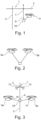
- the crane 1 can be designed as a tower crane, the tower 2 of which carries a boom 3 on which a trolley 4 is movably mounted.
- the boom 3 can be rotated about an upright axis together with the tower 2 or without the tower 2 - depending on the design of the crane as a top or bottom slewing crane - for which a slewing gear drive is provided.
- the boom 3 could possibly also be designed to be luffed up and down about a lying transverse axis, with a suitable luffing drive, for example in conjunction with the Boom bracing could be provided.
- the trolley 4 mentioned can be moved using a trolley winch or another trolley drive.
- the drive devices mentioned can be controlled by a control device 5, which can include a stationary operating unit with suitable input means 19, for example in the form of joysticks in the crane operator's cabin 6 or at the control station of the crane or a remote control station and/or also have a mobile operating unit with appropriate input means can.
- a mobile operating unit can be designed, for example, in the form of a radio remote control that the crane operator can carry with him when he walks across the construction site in the crane work area in order to be able to control the crane outside the crane operator's cabin 6.
- At least one flying drone 9 is provided, which is connected to the load 20 and/or is connected to the load hook 8 by a pulling and/or pushing means, in particular a lifting rope or a push rod.
- At least one camera can be mounted on the flying drone, by means of which a camera image of the load hook 8 and/or the load hook surroundings can be provided.
- the said camera image is advantageously a live or real-time image in the sense of a television or video image and is transmitted wirelessly from the camera 10 of the flying drone 9 to a display unit and/or the control device 5 of the crane 1, the said display unit being, for example, a machine operator display according to Art a tablet or a screen or a monitor that can be mounted in the crane operator's cabin 6. If a remote control stand or a mobile control unit is used to control the crane 1 in the manner mentioned above used, said display unit 11 can be provided in the remote control stand or on the mobile control unit.
- the flight drone 9 is provided with a remote control device 12, which allows the flight drone 9 to be controlled remotely, in particular to control the flight control units such as rotor blades in order to remotely control the flight position of the flight drone 9.
- a corresponding remote control module is advantageously integrated into the control device 5 and/or can be provided in the crane operator's cabin 6 and/or the remote control stand or the mobile operating unit, for example equipped with corresponding joysticks.
- the control of the flight drone 9a; 9b include a flight computer 90, which can be provided on the flight drone and can include, for example, one or more microprocessors, one or more program memories and other hardware and / or software components in order to process a flight control program.
- said flight computer 90 can communicate with a ground station 110 via a communication link 100, for example a radio link, in order to transmit data from the flight computer 90 to the ground station 110 or vice versa from the ground station 110 to the flight computer 90.
- telemetry data such as GPS position, rotor speed, lifting force and other drone parameters can be transmitted from the flight computer 90 to the ground station 110 in order to be monitored and/or evaluated there.
- data such as control signals can be transmitted from the ground station 110 to the flight computer 90 in order to influence the control of the flight drone there.
- Said flight computer 90 can be operated by one on the flight drone 9a; 9b provided sensors 120 are supplied with sensor signals that indicate a current operating state of the flight drone and / or movement parameters specify, for example, a position signal such as a GPS position, air pressure, wind speed, compass data or similar.
- a position signal such as a GPS position, air pressure, wind speed, compass data or similar.
- the flight computer 90 can execute or process flight regulation and/or control and control drives of the flight drone, in particular by a speed and/or a torque of a respective rotor to vary.
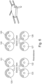
- the flight drone 9a; 9b have several rotors 120 to 127, which, for example, are arranged one above the other in two levels and can be arranged crosswise in each level.
- the drives of the rotors 120 to 126 and/or their drive gears are advantageously configured in such a way that rotors lying opposite each other in one plane - for example 120 and 122 as well as 121 and 123 - each rotate in the same direction, but rotors lying next to one another rotate in opposite directions.
- the directions of rotation in the two rotor planes can be reversed, so that a pair of rotors lying one above the other/beneath each other rotate in opposite directions to the two rotor planes, cf. Fig. 6 .
- the flight movement and/or the provided load capacity or lifting and/or pulling load can be specifically controlled by the thrust distribution on the rotors, in particular by the speeds on the individual rotors 120 to 126 and/or their torque individually, in pairs or is varied in groups in order to cause the flight drone 9a, 9b to rise and/or fall and/or pitch and/or roll and/or yaw.
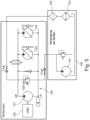
- the flight drone 9a; 9b have a hydraulic drive train 130 for driving the rotors 120 to 127, wherein the hydraulic drive train 130 or the hydrostatic transmission can include a hydrostat 131 working as a pump, which can be driven by a drive motor 132.
- the drive motor mentioned 131 can advantageously be designed as an internal combustion engine VKM, for example in the form of a diesel engine or a gasoline engine or a gas internal combustion engine.
- the hydrostatic drive train 130 further comprises several further hydrostats 133 and 134, each of which is drive-connected to one of the rotors 120 to 127 and can be supplied by the hydrostat 131, which works as a pump.
- the hydrostat 131 which works as a pump.
- FIG. 5 Only two hydrostats 133 and 134 working as motors are shown. However, it is understood that further such hydrostats working as motors can be provided in order to be able to drive the individual rotors that drive the flying drone 9a; 9b has.
- Such further hydrostats can be connected in particular in parallel to the hydrostats 133 and 134 shown with the supply and return lines, which are connected to the hydrostat 131 working as a pump.
- the hydrostats 131, 133 and 134 mentioned are each designed as adjustable hydrostats whose displacement volume or pump power can be varied.
- swashplate units can be used that are designed to be adjustable in the adjustment angle.
- the procedure can in particular be as follows:
- the drive motor 132 can be operated at least approximately constantly, for example under full load or at least approximately under full load or in an operating range that is favorable in terms of efficiency.
- the hydrostat 131 driven by the internal combustion engine 132 converts the rotary drive movement of the drive motor 132 into hydraulic pressure, which supplies the other hydrostats 133, 134.
- the torque and/or the speed of the rotors connected to the drive can be varied. Additional hydraulic ones can also be used
- Actuators are used in the hydrostatic drive train to control the rotors, for example via pressure control valves, mass flow throttles, etcetera.
- the flying drone 9a, 9b can advantageously be coupled to a supply station 140, which can be installed on the ground or elsewhere, for example on the crane, in order to cool and/or filter the hydrostatic drive train of the flying drone and/or or to pre-stress in print.
- the supply station 140 can have a pressure source 141, which can be coupled to the hydrostatic drive train, for example via a check valve and / or a check valve, in order to bias the hydrostatic pressure circuit to a desired target operating pressure.
- the supply station may include a filtering device 142 and/or a cooling device 143, which is/are also connectable to the hydrostatic drive train in order to filter and/or cool the hydraulic oil when the aerial drone is coupled to the supply station 140.
- the common control device 5 can have a main control device 5a with input means 19 for entering flight and/or crane movement requests, from which control signals are generated to the at least one flight drone 9a and/or the crane 1 based on the entered movement requests and transmitted, and have an additional control device 5b, from which control commands for the at least one and / or the further flight drone 9a; 9b are generated and transmitted depending on the flight or crane movements that were initiated by the main control device 5a.
- the position of the flying drone 9 relative to the crane 1 and / or its load hook can be controlled largely autonomously and independently of the crane, at least in an autonomous control mode, for example in a manner known per se via the aforementioned joysticks of the remote control device 12.
- the autonomous control module of the position control device 13 can be flown to a desired position of the flight drone 9 relative to the load hook 8.
- the common steering device 5 or its additional control device 5b in particular its position control device 13, can have an automatic sequence control module in order to achieve a predetermined position of the flight drone 9 - for example the desired position arbitrarily approached by the autonomous position control module and / or a predetermined, pre-programmed one Position - to be maintained, even if the crane 1 carries out crane movements and / or the load hook 8 is moved, so that the flying drone 9 largely automatically follows the load hook 8 and maintains the predetermined relative position.
- a position determining device 18 is advantageously provided, which automatically continuously or cyclically determines the position of the flying drone 9 relative to the crane 1 and/or its load hook 8, so that the position control device 13 can control the flying drone 9 depending on the determined relative position.
- the flight drone 9 can, for example, include a GPS unit 14, by means of which the absolute spatial position of the flight drone 9 is determined and transmitted to the position control device 13.
- the position of the load hook 8 can be determined so that the position control device 13 can remotely control the flying drone 9 to maintain the relative position.
- the load hook position can in principle also be determined using GPS, for example by integrating a GPS unit into the load hook.
- the load hook position can also be determined from the position of the crane components, in particular calculated by the control device 5 of the crane, for example by detecting the angle of rotation of the boom, the position of the trolley 4 on the boom 3 and the unwinding length of the hoist rope 7, from which If the installation location of the crane 1 is known, the load hook position is different can at least be approximately determined if one ignores dynamic pendulum movements or wind influences.
- the position of the flight drone 9 can also be determined relatively in a coordinate system that is fixed to the crane, i.e. that rotates with the crane.
- transmitter/receiver units for example in the form of transponder units 15, can be provided on the crane 1, for example on its boom 3 and its tower 2, possibly also on its trolley 4 and/or its load hook 8, which are advantageously located on several spaced apart units Places on crane 1 are attached.
- the above-mentioned transmitter/receiver units 15 can communicate with a corresponding transmitter/receiver unit 16 on the flight drone 9.
- the common control device 5 can also include a lifting and/or traction control module, by means of which certain operating parameters of the flight drone 9a or 9b, such as rotor speed and/or angle of attack, are controlled so that the load-carrying device is at the Flight drone, for example a hoisting rope, which connects the drone to the load 20 or the load hook 8, is acted upon with a desired force, in particular with a specific amount of force and / or a specific direction of force.
- a lifting and/or traction control module by means of which certain operating parameters of the flight drone 9a or 9b, such as rotor speed and/or angle of attack, are controlled so that the load-carrying device is at the Flight drone, for example a hoisting rope, which connects the drone to the load 20 or the load hook 8, is acted upon with a desired force, in particular with a specific amount of force and / or a specific direction of force.
- the tensile stress and/or the inclination ⁇ of the mentioned hoist rope, which connects the drone 9 to the load 20 can be monitored relative to the horizontal using a suitable sensor system and, depending on this, the Flight drone can be controlled in order to pull the load 20 by means of the drone 9 in a certain direction with a certain strength or force.
- flying drones 9a and 9b can also be connected to the load 20 or the load hook 8, whereby it can be advantageous, for example, to position at least one pair of flying drones 9a, b on opposite sides of the load hook 8 and with the load 20 or the Load hook 8 itself to be connected in order to be able to exert horizontal forces F H in approximately opposite directions on the load hook 8 or the load 20 attached to it or to be able to compensate for each other if, for example, only the lifting ability of the flying drones 9a, b is required.
- the common control device 5 can keep the two flying drones 9a and 9b at a distance from one another and fly together along a specific flight path to a destination.
- the flying drones 9 a, b can, for example, be attached to the common load via separate lifting ropes, or can also be attached to a common lifting yoke, to which the load 20 is in turn attached.
Landscapes
- Engineering & Computer Science (AREA)
- Aviation & Aerospace Engineering (AREA)
- Mechanical Engineering (AREA)
- Radar, Positioning & Navigation (AREA)
- Remote Sensing (AREA)
- Physics & Mathematics (AREA)
- General Physics & Mathematics (AREA)
- Automation & Control Theory (AREA)
- Control And Safety Of Cranes (AREA)
- Forklifts And Lifting Vehicles (AREA)
- Jib Cranes (AREA)
Claims (15)
- Procédé de levage d'une charge (20), dans lequel au moins un drone volant (9) porte au moins une partie de la charge (20) et la charge (20) est reliée à un autre drone volant (9b) et est partiellement portée et/ou dirigée par l'autre drone volant (9b), les deux drones volants (9a, b) étant commandés ensemble par un appareil de commande commun (5) pour commander les mouvements de vol de manière coordonnée, caractérisé en ce qu'une force de levage et/ou de traction et/ou une trajectoire de vol des drones volants (9a ; 9b) sont commandées par variation d'une vitesse de rotation de rotor et/ou d'un couple de rotation de rotor, les drones volants (9a ; 9b) présentant chacun une chaîne cinématique hydrostatique (130) pour entraîner au moins un rotor (120-127) comprenant au moins un hydrostat (131) fonctionnant en tant que pompe, qui peut être entraîné par un moteur d'entraînement (132), et au moins un autre hydrostat (133, 134) fonctionnant en tant que moteur, qui peut être relié au rotor, et ladite vitesse de rotation de rotor et/ou le couple de rotation de rotor étant commandés en ajustant un volume d'absorption de l'hydrostat et/ou un angle de pivotement de l'hydrostat et/ou un débit de pompage de l'hydrostat.
- Procédé selon la revendication précédente, dans lequel la charge (20) est en outre reliée à un crochet de charge (8) d'une grue et est partiellement portée et dirigée par la grue (1), les drones volants étant commandés conjointement avec la grue (1) par un appareil de commande commun (5) de manière coordonnée.
- Procédé selon l'une quelconque des revendications précédentes, dans lequel l'appareil de commande commun (5) présente un appareil de commande principal (5a) avec des moyens d'entrée (19) pour entrer des souhaits de mouvement de vol et/ou de grue, à partir duquel des signaux de commande sont générés et transmis à l'au moins un drone volant (9a) et/ou à la grue (1) sur la base des souhaits de mouvement entrés, et un appareil de commande supplémentaire (5b) à partir duquel des instructions de commande pour l'au moins un et/ou l'autre drone volant (9a ; 9b) sont générées et transmises en fonction des mouvements de vol ou de grue ordonnés par l'appareil de commande principal (5a).
- Procédé selon l'une quelconque des revendications précédentes, dans lequel le moteur d'entraînement (132) est configuré sous forme de moteur à combustion interne et fonctionne dans un état de fonctionnement au moins approximativement constant, notamment au moins approximativement dans la plage de pleine charge, les variations de vitesse de rotation et/ou les variations de couple de rotation sur le rotor étant commandées de manière variable par ajustement de l'au moins un hydrostat (133, 134 ; 131).
- Procédé selon l'une quelconque des revendications précédentes, dans lequel les drones volants (9a ; 9b) sont commandés de telle sorte qu'une force (F) ayant une composante horizontale (FH) est exercée sur la charge (20), les drones volants (9) étant commandés de telle sorte que la composante horizontale (FH) s'oppose à un mouvement pendulaire de la charge (20) et/ou à une force du vent.
- Procédé selon l'une quelconque des revendications précédentes, dans lequel les drones volants (9) sont commandés de telle sorte que la charge (20) est tournée autour d'un axe vertical lors du levage, au moins un drone volant (9) étant piloté le long d'un trajet au moins approximativement hélicoïdal autour d'un axe vertical à travers la charge (20) lors du levage de la charge (20).
- Procédé selon l'une quelconque des revendications précédentes, dans lequel les drones volants (9) sont télécommandés de manière autonome dans un mode de commande autonome de telle sorte qu'un drone volant (9) se déplace vers différentes positions pouvant respectivement être prédéfinies par rapport à un drone de guidage (9a).
- Procédé selon l'une quelconque des revendications précédentes, dans lequel des paramètres de fonctionnement déterminés de chaque drone volant (9), notamment la vitesse de rotation et/ou l'angle d'attaque du rotor, sont commandés par l'appareil de commande (5) de telle sorte qu'un moyen de réception de charge sur chaque drone volant (9), qui relie le drone volant (9) à la charge (20), est soumis à une valeur de force déterminée et à une direction de force déterminée, les directions de force des différents drones volants étant dirigées dans différentes directions.
- Dispositif de levage d'une charge (20), dans lequel au moins un drone volant (9) est relié à la charge (20) par un moyen de réception de charge pour porter au moins une partie de la charge (20) et la charge (20) est reliée à un autre drone volant (9b), un appareil de commande commun (5) étant prévu pour commander les deux drones volants (9a, b) de manière coordonnée, caractérisé en ce qu'une force de levage et/ou de traction et/ou une trajectoire de vol des drones volants (9a ; 9b) peuvent être commandées par variation d'une vitesse de rotation de rotor et/ou d'un couple de rotation de rotor, les drones volants (9a ; 9b) présentant chacun une chaîne cinématique hydrostatique (130) pour entraîner au moins un rotor (120-127) comprenant au moins un hydrostat (131) fonctionnant en tant que pompe, qui peut être entraîné par un moteur d'entraînement (132), et au moins un autre hydrostat (133, 134) fonctionnant en tant que moteur, qui peut être relié au rotor, et ladite vitesse de rotation de rotor et/ou le couple de rotation de rotor peuvent être commandés en ajustant un volume d'absorption de l'hydrostat et/ou un angle de pivotement de l'hydrostat et/ou un débit de pompage de l'hydrostat.
- Dispositif selon la revendication précédente, dans lequel la charge (20) est en outre reliée à un crochet de charge (8) d'une grue (1) et l'appareil de commande commun (5) est configuré pour commander les deux drones volants de manière coordonnée conjointement avec la grue (1).
- Dispositif selon l'une quelconque des deux revendications précédentes, dans lequel l'appareil de commande commun (5) présente un appareil de commande principal (5a) avec des moyens d'entrée (19) pour entrer des souhaits de vol et/ou de mouvement de la grue, à partir duquel des signaux de commande sont générés et transmis à l'au moins un drone volant (9a) et/ou à la grue (1) sur la base des souhaits de mouvement entrés, et un appareil de commande supplémentaire (5b) configuré pour générer des instructions de commande pour l'au moins un et/ou l'autre drone volant (9a ; 9b) en fonction des mouvements de vol ou de grue ordonnés par l'appareil de commande principal (5a).
- Dispositif selon l'une quelconque des revendications précédentes 9 à 11, dans lequel l'appareil de commande (5) présente un dispositif de commande de position (13) qui possède un module de commande de suivi automatique pour commander le drone volant (9) en fonction d'une position de drone de guidage de telle sorte que le drone volant (9) suit automatiquement les mouvements du drone de guidage et maintient une position souhaitée par rapport au drone de guidage même lors des mouvements du drone de guidage, l'appareil de commande (5) étant configuré pour commander les drones volants (9) de telle sorte que, lors du levage de la charge (20), l'un des drones volants (9) vole le long d'une trajectoire hélicoïdale autour d'une ligne verticale passant par la charge (20).
- Dispositif selon la revendication 10 ou l'une quelconque des revendications 11 et 12 qui s'y rapportent, dans lequel un/le dispositif de commande de position (13) présente un module de commande autonome pour télécommander de manière autonome le drone volant (9) de telle sorte que le drone volant (9) se déplace vers différentes positions souhaitées par rapport à la grue et/ou à son crochet de charge.
- Dispositif selon la revendication 10 ou l'une quelconque des revendications 11 à 13 qui s'y rapportent, dans lequel un appareil de détermination de position (18) est prévu pour déterminer la position du drone volant (9) par rapport à un drone de guidage, un/le dispositif de commande de position (13) étant configuré pour commander le drone volant (9) en fonction de la position relative déterminée automatiquement, le drone volant (9) présentant une unité GPS pour déterminer la position absolue du drone volant (9), le dispositif de commande de position (13) pour commander la position du drone volant (9) par rapport à la grue étant configuré pour commander le drone volant (9) en fonction des données de position absolue du drone volant (9) et des données de position absolue de la grue, l'appareil de détermination de position (18) présentant un dispositif de localisation de signal pour localiser un signal émis par le drone volant (9), ledit dispositif de localisation de signal présentant des unités d'émission/réception (15) montées sur la grue, espacées les unes des autres, pour communiquer avec une unité d'émission/réception (16) sur le drone volant (9), ainsi qu'un appareil d'évaluation pour évaluer les signaux transmis entre les unités d'émission/réception (15) côté grue et l'unité d'émission/réception (16) côté drone en ce qui concerne des propriétés de signal prédéterminées, notamment en ce qui concerne le temps de propagation du signal et/ou l'intensité du signal, et pour déterminer la position du drone volant (9) par rapport à la grue (1) à partir des propriétés du signal.
- Dispositif selon l'une quelconque des revendications 9 à 14 précédentes, dans lequel un moteur à combustion interne (VKM) est prévu en tant que moteur d'entraînement (132), le drone volant (9) étant configuré sous forme de multicoptère et présentant plusieurs rotors, la chaîne cinématique hydrostatique (130) comprenant plusieurs hydrostats (133, 134) fonctionnant en tant que moteur, qui sont respectivement reliés en entraînement à un rotor et sont configurés de manière à pouvoir être ajustés individuellement, afin de commander individuellement la vitesse de rotation des rotors reliés aux hydrostats respectifs.
Applications Claiming Priority (3)
| Application Number | Priority Date | Filing Date | Title |
|---|---|---|---|
| DE102017112765.8A DE102017112765A1 (de) | 2017-06-09 | 2017-06-09 | Verfahren und Vorrichtung zum Heben einer Last |
| EP18730740.0A EP3619111B1 (fr) | 2017-06-09 | 2018-06-08 | Procédé et dispositif pour lever une charge |
| PCT/EP2018/065182 WO2018224657A1 (fr) | 2017-06-09 | 2018-06-08 | Procédé et dispositif pour lever une charge |
Related Parent Applications (2)
| Application Number | Title | Priority Date | Filing Date |
|---|---|---|---|
| EP18730740.0A Division-Into EP3619111B1 (fr) | 2017-06-09 | 2018-06-08 | Procédé et dispositif pour lever une charge |
| EP18730740.0A Division EP3619111B1 (fr) | 2017-06-09 | 2018-06-08 | Procédé et dispositif pour lever une charge |
Publications (2)
| Publication Number | Publication Date |
|---|---|
| EP3733512A1 EP3733512A1 (fr) | 2020-11-04 |
| EP3733512B1 true EP3733512B1 (fr) | 2023-10-18 |
Family
ID=62597497
Family Applications (2)
| Application Number | Title | Priority Date | Filing Date |
|---|---|---|---|
| EP20182196.4A Active EP3733512B1 (fr) | 2017-06-09 | 2018-06-08 | Procédé et dispositif de levage d'une charge |
| EP18730740.0A Active EP3619111B1 (fr) | 2017-06-09 | 2018-06-08 | Procédé et dispositif pour lever une charge |
Family Applications After (1)
| Application Number | Title | Priority Date | Filing Date |
|---|---|---|---|
| EP18730740.0A Active EP3619111B1 (fr) | 2017-06-09 | 2018-06-08 | Procédé et dispositif pour lever une charge |
Country Status (9)
| Country | Link |
|---|---|
| US (1) | US11981433B2 (fr) |
| EP (2) | EP3733512B1 (fr) |
| CN (1) | CN110914152B (fr) |
| AU (1) | AU2018280853B2 (fr) |
| BR (1) | BR112019025789A2 (fr) |
| DE (1) | DE102017112765A1 (fr) |
| ES (1) | ES2965874T3 (fr) |
| RU (1) | RU2768693C2 (fr) |
| WO (1) | WO2018224657A1 (fr) |
Families Citing this family (30)
| Publication number | Priority date | Publication date | Assignee | Title |
|---|---|---|---|---|
| DE102017112765A1 (de) | 2017-06-09 | 2018-12-13 | Liebherr-Werk Biberach Gmbh | Verfahren und Vorrichtung zum Heben einer Last |
| WO2019001664A1 (fr) * | 2017-06-30 | 2019-01-03 | Vestas Wind Systems A/S | Système et procédé de manutention de composants d'éolienne pour un assemblage desdits composants d'éolienne |
| US10906783B2 (en) * | 2017-08-25 | 2021-02-02 | Columbia Helicopters, Inc. | Load placement system |
| US11209836B1 (en) | 2018-02-08 | 2021-12-28 | Vita Inclinata Technologies, Inc. | Long line loiter apparatus, system, and method |
| WO2021194628A2 (fr) * | 2020-01-28 | 2021-09-30 | Vita Inclinata Technologies, Inc. | Commande de procédé, système et appareil de système de charge de drone |
| US12434813B2 (en) | 2018-02-08 | 2025-10-07 | Vita Inclinata Ip Holdings Llc | Bidirectional thrust apparatus, system and method |
| US11142433B2 (en) | 2018-02-08 | 2021-10-12 | Vita Inclinata Technologies, Inc. | Bidirectional thrust apparatus, system, and method |
| US12304779B2 (en) | 2018-02-08 | 2025-05-20 | Vita Inclinata Ip Holdings Llc | On-board power and remote power for suspended load control apparatuses, systems, and methods |
| US11945697B2 (en) | 2018-02-08 | 2024-04-02 | Vita Inclinata Ip Holdings Llc | Multiple remote control for suspended load control equipment apparatus, system, and method |
| US12246952B2 (en) | 2018-02-08 | 2025-03-11 | Vita Inclintata IP Holdings LLC | Hoist and deployable equipment apparatus, system, and method |
| US11142316B2 (en) | 2018-02-08 | 2021-10-12 | Vita Inclinata Technologies, Inc. | Control of drone-load system method, system, and apparatus |
| US11964849B2 (en) * | 2018-03-02 | 2024-04-23 | Vestas Wind Systems A/S | System and method for handling wind turbine components for assembly thereof |
| US11746951B2 (en) | 2019-02-26 | 2023-09-05 | Vita Inclinata Ip Holdings Llc | Cable deployment apparatus, system, and methods for suspended load control equipment |
| US11834305B1 (en) | 2019-04-12 | 2023-12-05 | Vita Inclinata Ip Holdings Llc | Apparatus, system, and method to control torque or lateral thrust applied to a load suspended on a suspension cable |
| US11618566B1 (en) | 2019-04-12 | 2023-04-04 | Vita Inclinata Technologies, Inc. | State information and telemetry for suspended load control equipment apparatus, system, and method |
| US12179922B2 (en) * | 2019-11-15 | 2024-12-31 | Rakuten Group, Inc. | Unmanned aircraft system, control device and control method |
| KR20220104048A (ko) | 2019-11-25 | 2022-07-25 | 비타 인클리나타 테크놀로지스 인코포레이티드 | 현수 하중 제어 장치, 시스템, 및 방법을 위한 커플링 |
| US12216480B2 (en) * | 2020-05-01 | 2025-02-04 | United States Of America, As Represented By The Secretary Of The Army | Aircraft multi-lift system with synchronized maneuvering and load feedback control |
| CN111927099B (zh) * | 2020-09-03 | 2020-12-25 | 上海建工集团股份有限公司 | 一种全尺寸3d打印系统及方法 |
| IT202100000788A1 (it) | 2021-01-18 | 2022-07-18 | E80 Group S P A | Apparato e metodo per la movimentazione di oggetti |
| JP7621160B2 (ja) * | 2021-03-31 | 2025-01-24 | 住友重機械建機クレーン株式会社 | 表示装置及び経路表示プログラム |
| WO2023280360A1 (fr) * | 2021-07-09 | 2023-01-12 | Vestas Wind Systems A/S | Système et procédé de réparation des dommages de bord d'attaque sur une pale d'éolienne |
| CN113946158A (zh) * | 2021-12-02 | 2022-01-18 | 中国地质调查局地球物理调查中心 | 基于无人机组投放震源体的地震波激发系统与方法 |
| JP7682112B2 (ja) * | 2022-01-04 | 2025-05-23 | 西松建設株式会社 | 撮影装置及び監視システム |
| US11620597B1 (en) | 2022-04-29 | 2023-04-04 | Vita Inclinata Technologies, Inc. | Machine learning real property object detection and analysis apparatus, system, and method |
| EP4532331A1 (fr) * | 2022-05-27 | 2025-04-09 | Singapore University of Technology and Design | Système à multiples monocoptères et son procédé de fonctionnement |
| RU2798089C1 (ru) * | 2022-12-28 | 2023-06-15 | Павел Русланович Андреев | Летательный аппарат (варианты), самоходный модуль, полезная нагрузка, система и способ для перемещения полезной нагрузки (варианты) |
| US11992444B1 (en) | 2023-12-04 | 2024-05-28 | Vita Inclinata Ip Holdings Llc | Apparatus, system, and method to control torque or lateral thrust applied to a load suspended on a suspension cable |
| CN117692358B (zh) * | 2023-12-12 | 2024-07-05 | 国网内蒙古东部电力有限公司呼伦贝尔供电公司 | 一种基于无人机挂载的实时可靠性状态检测报警系统 |
| US20260042643A1 (en) * | 2024-08-12 | 2026-02-12 | International Business Machines Corporation | Mitigating oscillation of a lift cable on a crane |
Family Cites Families (26)
| Publication number | Priority date | Publication date | Assignee | Title |
|---|---|---|---|---|
| US3799358A (en) * | 1972-06-12 | 1974-03-26 | Zachry Co H B | Helicopter tail rotor device |
| SU1763292A1 (ru) * | 1990-11-13 | 1992-09-23 | Научно-производственное объединение применения гражданской авиации в народном хозяйстве | Способ пилотировани при монтаже груза с помощью двух вертолетов |
| JPH05193584A (ja) * | 1992-01-17 | 1993-08-03 | Mitsubishi Heavy Ind Ltd | 吊下荷物の姿勢安定装置 |
| JPH0710464A (ja) * | 1993-06-24 | 1995-01-13 | Hitachi Constr Mach Co Ltd | 吊り荷の位置決め装置 |
| US8157205B2 (en) * | 2006-03-04 | 2012-04-17 | Mcwhirk Bruce Kimberly | Multibody aircrane |
| JP5018256B2 (ja) * | 2007-06-08 | 2012-09-05 | コベルコクレーン株式会社 | クレーン作業車 |
| CA2666889A1 (fr) * | 2008-05-27 | 2009-11-27 | Wilfred P. So | Systeme et methode d'elevation de plusieurs aeronefs a l'aide d'une charge utile commune |
| EP2172412A1 (fr) * | 2008-10-06 | 2010-04-07 | Regione Autonoma Valle d'Aosta Direzione Protezione Civile | Dispositif de stabilisation de civière |
| JP5303798B2 (ja) * | 2010-07-16 | 2013-10-02 | 株式会社小松製作所 | 無人車両の走行システムおよびその走行制御方法 |
| RU2449924C1 (ru) * | 2010-11-15 | 2012-05-10 | Открытое акционерное общество "Московский вертолетный завод им.М.Л. Миля" | Система для подъема и транспортировки по воздуху тяжелых грузов |
| WO2013006625A2 (fr) * | 2011-07-05 | 2013-01-10 | Trimble Navigation Limited | Assistance pour manœuvre de grue |
| US8591161B1 (en) * | 2011-10-04 | 2013-11-26 | The Boeing Company | Maneuvering autonomous rotorcraft cargo attachment system with motion compensation |
| FI126364B (fi) * | 2012-05-25 | 2016-10-31 | Konecranes Global Oy | Nostolaitteen liikematkan määritys |
| US9079662B1 (en) * | 2012-10-01 | 2015-07-14 | The Boeing Company | Co-operative, modular, unmanned, vertical lift cargo vehicles |
| US10273004B2 (en) * | 2013-06-13 | 2019-04-30 | The Boeing Company | Systems and methods for moving a load using unmanned vehicles |
| US9205922B1 (en) * | 2013-07-17 | 2015-12-08 | The Boeing Company | Systems and methods for implementing a payload distribution system |
| US9073624B2 (en) * | 2013-12-09 | 2015-07-07 | The Boeing Company | Methods and apparatus to cooperatively lift a payload |
| US9555899B2 (en) * | 2014-03-27 | 2017-01-31 | The United States Of America As Represented By The Secretary Of The Navy | Mobile arresting system |
| US9146557B1 (en) * | 2014-04-23 | 2015-09-29 | King Fahd University Of Petroleum And Minerals | Adaptive control method for unmanned vehicle with slung load |
| WO2016068767A1 (fr) * | 2014-10-30 | 2016-05-06 | Acc Innovation Ab | Véhicule aérien à rotors multiples |
| US9944366B2 (en) * | 2015-05-19 | 2018-04-17 | Rujing Tang | Unmanned aerial vehicle system and methods for use |
| DE102015119279A1 (de) * | 2015-11-09 | 2017-05-11 | Antony Pfoertzsch | Unbemanntes Flugobjekt sowie Steuerung und Fernsteuerung hierfür und Verfahren zum Steuern eines unbemannten Flugobjekts |
| DE102016000353A1 (de) * | 2016-01-14 | 2017-07-20 | Liebherr-Components Biberach Gmbh | Kran-, Baumaschinen- oder Flurförderzeug-Simulator |
| US10457393B2 (en) * | 2016-04-05 | 2019-10-29 | Walmart Apollo, Llc | Apparatuses and methods for receiving aerial vehicle delivery |
| DE102017112765A1 (de) | 2017-06-09 | 2018-12-13 | Liebherr-Werk Biberach Gmbh | Verfahren und Vorrichtung zum Heben einer Last |
| US11964849B2 (en) * | 2018-03-02 | 2024-04-23 | Vestas Wind Systems A/S | System and method for handling wind turbine components for assembly thereof |
-
2017
- 2017-06-09 DE DE102017112765.8A patent/DE102017112765A1/de not_active Withdrawn
-
2018
- 2018-06-08 BR BR112019025789-6A patent/BR112019025789A2/pt not_active Application Discontinuation
- 2018-06-08 RU RU2019143683A patent/RU2768693C2/ru active
- 2018-06-08 EP EP20182196.4A patent/EP3733512B1/fr active Active
- 2018-06-08 WO PCT/EP2018/065182 patent/WO2018224657A1/fr not_active Ceased
- 2018-06-08 CN CN201880038216.3A patent/CN110914152B/zh active Active
- 2018-06-08 AU AU2018280853A patent/AU2018280853B2/en active Active
- 2018-06-08 ES ES18730740T patent/ES2965874T3/es active Active
- 2018-06-08 EP EP18730740.0A patent/EP3619111B1/fr active Active
-
2019
- 2019-12-09 US US16/708,266 patent/US11981433B2/en active Active
Also Published As
| Publication number | Publication date |
|---|---|
| DE102017112765A1 (de) | 2018-12-13 |
| RU2019143683A (ru) | 2021-07-09 |
| EP3619111B1 (fr) | 2023-09-27 |
| AU2018280853A1 (en) | 2020-01-16 |
| AU2018280853B2 (en) | 2024-02-29 |
| ES2965874T3 (es) | 2024-04-17 |
| US20200180763A1 (en) | 2020-06-11 |
| CN110914152A (zh) | 2020-03-24 |
| RU2019143683A3 (fr) | 2021-10-12 |
| EP3733512A1 (fr) | 2020-11-04 |
| CN110914152B (zh) | 2024-04-23 |
| EP3619111A1 (fr) | 2020-03-11 |
| BR112019025789A2 (pt) | 2020-07-07 |
| RU2768693C2 (ru) | 2022-03-24 |
| WO2018224657A1 (fr) | 2018-12-13 |
| US11981433B2 (en) | 2024-05-14 |
Similar Documents
| Publication | Publication Date | Title |
|---|---|---|
| EP3733512B1 (fr) | Procédé et dispositif de levage d'une charge | |
| EP3411534B1 (fr) | Procédé et dispositif de commande d'une grue, d'une pelle mécanique, d'un engin à chenilles ou d'un engin de construction similaire | |
| EP1444162B1 (fr) | Grue automotrice munie d'un dispositif d'augmentation de levage | |
| DE102014015335B4 (de) | Generative Fertigungsvorrichtung und Fertigungsverfahren zm schichtweisen Aufbau von Bauwerken | |
| DE102019122796A1 (de) | Kran und Verfahren zum Steuern eines solchen Krans | |
| WO1995006178A1 (fr) | Manipulateur de taille importante, notamment pour pompes a beton automatiques, et son procede de manipulation | |
| EP2272785A1 (fr) | Procédé de commande d'un entraînement de grue | |
| EP3297946B1 (fr) | Treuil de puits mobile | |
| AT520008A1 (de) | Verfahren zum Dämpfen von Drehschwingungen eines Lastaufnahmeelements einer Hebeeinrichtung | |
| EP4402087A1 (fr) | Grue | |
| DE102019121550A1 (de) | Transporteinheit und System zum Transport eines Objekts | |
| EP3953287B1 (fr) | Dispositif pour la commande d'une charge suspendue à une corde | |
| DE202019000750U1 (de) | Selbstfahrendes Fahrzeug zum Bewegen von Platten-Transportgestellen | |
| EP3328781B1 (fr) | Treuil de puits mobile | |
| EP2789488A2 (fr) | Système d'entraînement | |
| DE102018100133A1 (de) | Kran mit Anti-Kollisions-Einrichtung sowie Verfahren zum Betreiben mehrerer solcher Krane | |
| DE4025749A1 (de) | Verfahren zum automatischen betreiben eines drehkrans | |
| DE102020214021A1 (de) | Verfahren zum Betrieb eines Kransystems und Kransystem | |
| WO2023025643A1 (fr) | Grue à tour pivotante, procédé et unité de commande pour faire fonctionner une grue à tour pivotante, chariot roulant et mécanisme de roulement pour chariot | |
| DE4405525A1 (de) | Kran mit einem Fahrantrieb zum horizontalen Verfahren einer an einem Seil hängenden Last | |
| EP2897892B1 (fr) | Procédé permettant de faire fonctionner une grue, et grue correspondante | |
| WO2022238228A1 (fr) | Système de télécommande pour engin de chantier et procédé de commande d'un engin de chantier | |
| DE102005002192B4 (de) | Verfahren zum Betrieb einer Krananlage, insbesondere eines Containerkrans, sowie Krananlage, insbesondere Containerkran | |
| DE8916221U1 (de) | Containerkrananlage | |
| DE102024125332A1 (de) | Transport einer Last mittels eines Gleitschirms |
Legal Events
| Date | Code | Title | Description |
|---|---|---|---|
| PUAI | Public reference made under article 153(3) epc to a published international application that has entered the european phase |
Free format text: ORIGINAL CODE: 0009012 |
|
| STAA | Information on the status of an ep patent application or granted ep patent |
Free format text: STATUS: THE APPLICATION HAS BEEN PUBLISHED |
|
| AC | Divisional application: reference to earlier application |
Ref document number: 3619111 Country of ref document: EP Kind code of ref document: P |
|
| AK | Designated contracting states |
Kind code of ref document: A1 Designated state(s): AL AT BE BG CH CY CZ DE DK EE ES FI FR GB GR HR HU IE IS IT LI LT LU LV MC MK MT NL NO PL PT RO RS SE SI SK SM TR |
|
| AX | Request for extension of the european patent |
Extension state: BA ME |
|
| STAA | Information on the status of an ep patent application or granted ep patent |
Free format text: STATUS: REQUEST FOR EXAMINATION WAS MADE |
|
| 17P | Request for examination filed |
Effective date: 20210504 |
|
| RBV | Designated contracting states (corrected) |
Designated state(s): AL AT BE BG CH CY CZ DE DK EE ES FI FR GB GR HR HU IE IS IT LI LT LU LV MC MK MT NL NO PL PT RO RS SE SI SK SM TR |
|
| RIC1 | Information provided on ipc code assigned before grant |
Ipc: B64U 101/60 20230101ALN20230411BHEP Ipc: B64D 1/22 20060101ALI20230411BHEP Ipc: B66C 13/04 20060101ALI20230411BHEP Ipc: G05D 1/10 20060101ALI20230411BHEP Ipc: B64C 39/02 20060101AFI20230411BHEP |
|
| GRAP | Despatch of communication of intention to grant a patent |
Free format text: ORIGINAL CODE: EPIDOSNIGR1 |
|
| STAA | Information on the status of an ep patent application or granted ep patent |
Free format text: STATUS: GRANT OF PATENT IS INTENDED |
|
| RIC1 | Information provided on ipc code assigned before grant |
Ipc: B64U 101/60 20230101ALN20230508BHEP Ipc: B64D 1/22 20060101ALI20230508BHEP Ipc: B66C 13/04 20060101ALI20230508BHEP Ipc: G05D 1/10 20060101ALI20230508BHEP Ipc: B64C 39/02 20060101AFI20230508BHEP |
|
| INTG | Intention to grant announced |
Effective date: 20230524 |
|
| GRAS | Grant fee paid |
Free format text: ORIGINAL CODE: EPIDOSNIGR3 |
|
| GRAA | (expected) grant |
Free format text: ORIGINAL CODE: 0009210 |
|
| STAA | Information on the status of an ep patent application or granted ep patent |
Free format text: STATUS: THE PATENT HAS BEEN GRANTED |
|
| AC | Divisional application: reference to earlier application |
Ref document number: 3619111 Country of ref document: EP Kind code of ref document: P |
|
| AK | Designated contracting states |
Kind code of ref document: B1 Designated state(s): AL AT BE BG CH CY CZ DE DK EE ES FI FR GB GR HR HU IE IS IT LI LT LU LV MC MK MT NL NO PL PT RO RS SE SI SK SM TR |
|
| REG | Reference to a national code |
Ref country code: GB Ref legal event code: FG4D Free format text: NOT ENGLISH |
|
| REG | Reference to a national code |
Ref country code: CH Ref legal event code: EP |
|
| REG | Reference to a national code |
Ref country code: DE Ref legal event code: R096 Ref document number: 502018013493 Country of ref document: DE |
|
| REG | Reference to a national code |
Ref country code: IE Ref legal event code: FG4D Free format text: LANGUAGE OF EP DOCUMENT: GERMAN |
|
| P01 | Opt-out of the competence of the unified patent court (upc) registered |
Effective date: 20231012 |
|
| REG | Reference to a national code |
Ref country code: LT Ref legal event code: MG9D |
|
| REG | Reference to a national code |
Ref country code: NL Ref legal event code: MP Effective date: 20231018 |
|
| PG25 | Lapsed in a contracting state [announced via postgrant information from national office to epo] |
Ref country code: NL Free format text: LAPSE BECAUSE OF FAILURE TO SUBMIT A TRANSLATION OF THE DESCRIPTION OR TO PAY THE FEE WITHIN THE PRESCRIBED TIME-LIMIT Effective date: 20231018 |
|
| PG25 | Lapsed in a contracting state [announced via postgrant information from national office to epo] |
Ref country code: GR Free format text: LAPSE BECAUSE OF FAILURE TO SUBMIT A TRANSLATION OF THE DESCRIPTION OR TO PAY THE FEE WITHIN THE PRESCRIBED TIME-LIMIT Effective date: 20240119 |
|
| PG25 | Lapsed in a contracting state [announced via postgrant information from national office to epo] |
Ref country code: IS Free format text: LAPSE BECAUSE OF FAILURE TO SUBMIT A TRANSLATION OF THE DESCRIPTION OR TO PAY THE FEE WITHIN THE PRESCRIBED TIME-LIMIT Effective date: 20240218 |
|
| PG25 | Lapsed in a contracting state [announced via postgrant information from national office to epo] |
Ref country code: LT Free format text: LAPSE BECAUSE OF FAILURE TO SUBMIT A TRANSLATION OF THE DESCRIPTION OR TO PAY THE FEE WITHIN THE PRESCRIBED TIME-LIMIT Effective date: 20231018 |
|
| PG25 | Lapsed in a contracting state [announced via postgrant information from national office to epo] |
Ref country code: ES Free format text: LAPSE BECAUSE OF FAILURE TO SUBMIT A TRANSLATION OF THE DESCRIPTION OR TO PAY THE FEE WITHIN THE PRESCRIBED TIME-LIMIT Effective date: 20231018 |
|
| PG25 | Lapsed in a contracting state [announced via postgrant information from national office to epo] |
Ref country code: LT Free format text: LAPSE BECAUSE OF FAILURE TO SUBMIT A TRANSLATION OF THE DESCRIPTION OR TO PAY THE FEE WITHIN THE PRESCRIBED TIME-LIMIT Effective date: 20231018 Ref country code: IS Free format text: LAPSE BECAUSE OF FAILURE TO SUBMIT A TRANSLATION OF THE DESCRIPTION OR TO PAY THE FEE WITHIN THE PRESCRIBED TIME-LIMIT Effective date: 20240218 Ref country code: GR Free format text: LAPSE BECAUSE OF FAILURE TO SUBMIT A TRANSLATION OF THE DESCRIPTION OR TO PAY THE FEE WITHIN THE PRESCRIBED TIME-LIMIT Effective date: 20240119 Ref country code: ES Free format text: LAPSE BECAUSE OF FAILURE TO SUBMIT A TRANSLATION OF THE DESCRIPTION OR TO PAY THE FEE WITHIN THE PRESCRIBED TIME-LIMIT Effective date: 20231018 Ref country code: BG Free format text: LAPSE BECAUSE OF FAILURE TO SUBMIT A TRANSLATION OF THE DESCRIPTION OR TO PAY THE FEE WITHIN THE PRESCRIBED TIME-LIMIT Effective date: 20240118 Ref country code: PT Free format text: LAPSE BECAUSE OF FAILURE TO SUBMIT A TRANSLATION OF THE DESCRIPTION OR TO PAY THE FEE WITHIN THE PRESCRIBED TIME-LIMIT Effective date: 20240219 |
|
| PG25 | Lapsed in a contracting state [announced via postgrant information from national office to epo] |
Ref country code: SE Free format text: LAPSE BECAUSE OF FAILURE TO SUBMIT A TRANSLATION OF THE DESCRIPTION OR TO PAY THE FEE WITHIN THE PRESCRIBED TIME-LIMIT Effective date: 20231018 Ref country code: RS Free format text: LAPSE BECAUSE OF FAILURE TO SUBMIT A TRANSLATION OF THE DESCRIPTION OR TO PAY THE FEE WITHIN THE PRESCRIBED TIME-LIMIT Effective date: 20231018 Ref country code: PL Free format text: LAPSE BECAUSE OF FAILURE TO SUBMIT A TRANSLATION OF THE DESCRIPTION OR TO PAY THE FEE WITHIN THE PRESCRIBED TIME-LIMIT Effective date: 20231018 Ref country code: NO Free format text: LAPSE BECAUSE OF FAILURE TO SUBMIT A TRANSLATION OF THE DESCRIPTION OR TO PAY THE FEE WITHIN THE PRESCRIBED TIME-LIMIT Effective date: 20240118 Ref country code: LV Free format text: LAPSE BECAUSE OF FAILURE TO SUBMIT A TRANSLATION OF THE DESCRIPTION OR TO PAY THE FEE WITHIN THE PRESCRIBED TIME-LIMIT Effective date: 20231018 Ref country code: HR Free format text: LAPSE BECAUSE OF FAILURE TO SUBMIT A TRANSLATION OF THE DESCRIPTION OR TO PAY THE FEE WITHIN THE PRESCRIBED TIME-LIMIT Effective date: 20231018 |
|
| PG25 | Lapsed in a contracting state [announced via postgrant information from national office to epo] |
Ref country code: DK Free format text: LAPSE BECAUSE OF FAILURE TO SUBMIT A TRANSLATION OF THE DESCRIPTION OR TO PAY THE FEE WITHIN THE PRESCRIBED TIME-LIMIT Effective date: 20231018 |
|
| REG | Reference to a national code |
Ref country code: DE Ref legal event code: R097 Ref document number: 502018013493 Country of ref document: DE |
|
| PG25 | Lapsed in a contracting state [announced via postgrant information from national office to epo] |
Ref country code: CZ Free format text: LAPSE BECAUSE OF FAILURE TO SUBMIT A TRANSLATION OF THE DESCRIPTION OR TO PAY THE FEE WITHIN THE PRESCRIBED TIME-LIMIT Effective date: 20231018 |
|
| PG25 | Lapsed in a contracting state [announced via postgrant information from national office to epo] |
Ref country code: SK Free format text: LAPSE BECAUSE OF FAILURE TO SUBMIT A TRANSLATION OF THE DESCRIPTION OR TO PAY THE FEE WITHIN THE PRESCRIBED TIME-LIMIT Effective date: 20231018 |
|
| PG25 | Lapsed in a contracting state [announced via postgrant information from national office to epo] |
Ref country code: SM Free format text: LAPSE BECAUSE OF FAILURE TO SUBMIT A TRANSLATION OF THE DESCRIPTION OR TO PAY THE FEE WITHIN THE PRESCRIBED TIME-LIMIT Effective date: 20231018 Ref country code: SK Free format text: LAPSE BECAUSE OF FAILURE TO SUBMIT A TRANSLATION OF THE DESCRIPTION OR TO PAY THE FEE WITHIN THE PRESCRIBED TIME-LIMIT Effective date: 20231018 Ref country code: RO Free format text: LAPSE BECAUSE OF FAILURE TO SUBMIT A TRANSLATION OF THE DESCRIPTION OR TO PAY THE FEE WITHIN THE PRESCRIBED TIME-LIMIT Effective date: 20231018 Ref country code: IT Free format text: LAPSE BECAUSE OF FAILURE TO SUBMIT A TRANSLATION OF THE DESCRIPTION OR TO PAY THE FEE WITHIN THE PRESCRIBED TIME-LIMIT Effective date: 20231018 Ref country code: EE Free format text: LAPSE BECAUSE OF FAILURE TO SUBMIT A TRANSLATION OF THE DESCRIPTION OR TO PAY THE FEE WITHIN THE PRESCRIBED TIME-LIMIT Effective date: 20231018 Ref country code: DK Free format text: LAPSE BECAUSE OF FAILURE TO SUBMIT A TRANSLATION OF THE DESCRIPTION OR TO PAY THE FEE WITHIN THE PRESCRIBED TIME-LIMIT Effective date: 20231018 Ref country code: CZ Free format text: LAPSE BECAUSE OF FAILURE TO SUBMIT A TRANSLATION OF THE DESCRIPTION OR TO PAY THE FEE WITHIN THE PRESCRIBED TIME-LIMIT Effective date: 20231018 |
|
| PLBE | No opposition filed within time limit |
Free format text: ORIGINAL CODE: 0009261 |
|
| STAA | Information on the status of an ep patent application or granted ep patent |
Free format text: STATUS: NO OPPOSITION FILED WITHIN TIME LIMIT |
|
| 26N | No opposition filed |
Effective date: 20240719 |
|
| PG25 | Lapsed in a contracting state [announced via postgrant information from national office to epo] |
Ref country code: SI Free format text: LAPSE BECAUSE OF FAILURE TO SUBMIT A TRANSLATION OF THE DESCRIPTION OR TO PAY THE FEE WITHIN THE PRESCRIBED TIME-LIMIT Effective date: 20231018 |
|
| PG25 | Lapsed in a contracting state [announced via postgrant information from national office to epo] |
Ref country code: SI Free format text: LAPSE BECAUSE OF FAILURE TO SUBMIT A TRANSLATION OF THE DESCRIPTION OR TO PAY THE FEE WITHIN THE PRESCRIBED TIME-LIMIT Effective date: 20231018 |
|
| PG25 | Lapsed in a contracting state [announced via postgrant information from national office to epo] |
Ref country code: MC Free format text: LAPSE BECAUSE OF FAILURE TO SUBMIT A TRANSLATION OF THE DESCRIPTION OR TO PAY THE FEE WITHIN THE PRESCRIBED TIME-LIMIT Effective date: 20231018 |
|
| REG | Reference to a national code |
Ref country code: CH Ref legal event code: PL |
|
| PG25 | Lapsed in a contracting state [announced via postgrant information from national office to epo] |
Ref country code: LU Free format text: LAPSE BECAUSE OF NON-PAYMENT OF DUE FEES Effective date: 20240608 |
|
| GBPC | Gb: european patent ceased through non-payment of renewal fee |
Effective date: 20240608 |
|
| PG25 | Lapsed in a contracting state [announced via postgrant information from national office to epo] |
Ref country code: IE Free format text: LAPSE BECAUSE OF NON-PAYMENT OF DUE FEES Effective date: 20240608 |
|
| PG25 | Lapsed in a contracting state [announced via postgrant information from national office to epo] |
Ref country code: BE Free format text: LAPSE BECAUSE OF NON-PAYMENT OF DUE FEES Effective date: 20240630 Ref country code: CH Free format text: LAPSE BECAUSE OF NON-PAYMENT OF DUE FEES Effective date: 20240630 |
|
| PG25 | Lapsed in a contracting state [announced via postgrant information from national office to epo] |
Ref country code: GB Free format text: LAPSE BECAUSE OF NON-PAYMENT OF DUE FEES Effective date: 20240608 |
|
| REG | Reference to a national code |
Ref country code: BE Ref legal event code: MM Effective date: 20240630 |
|
| PGFP | Annual fee paid to national office [announced via postgrant information from national office to epo] |
Ref country code: FR Payment date: 20250617 Year of fee payment: 8 |
|
| REG | Reference to a national code |
Ref country code: AT Ref legal event code: MM01 Ref document number: 1622235 Country of ref document: AT Kind code of ref document: T Effective date: 20240608 |
|
| PG25 | Lapsed in a contracting state [announced via postgrant information from national office to epo] |
Ref country code: FI Free format text: LAPSE BECAUSE OF FAILURE TO SUBMIT A TRANSLATION OF THE DESCRIPTION OR TO PAY THE FEE WITHIN THE PRESCRIBED TIME-LIMIT Effective date: 20231019 |
|
| PGFP | Annual fee paid to national office [announced via postgrant information from national office to epo] |
Ref country code: DE Payment date: 20250630 Year of fee payment: 8 |
|
| PG25 | Lapsed in a contracting state [announced via postgrant information from national office to epo] |
Ref country code: AT Free format text: LAPSE BECAUSE OF NON-PAYMENT OF DUE FEES Effective date: 20240608 |
|
| PG25 | Lapsed in a contracting state [announced via postgrant information from national office to epo] |
Ref country code: CY Free format text: LAPSE BECAUSE OF FAILURE TO SUBMIT A TRANSLATION OF THE DESCRIPTION OR TO PAY THE FEE WITHIN THE PRESCRIBED TIME-LIMIT; INVALID AB INITIO Effective date: 20180608 |
|
| PG25 | Lapsed in a contracting state [announced via postgrant information from national office to epo] |
Ref country code: HU Free format text: LAPSE BECAUSE OF FAILURE TO SUBMIT A TRANSLATION OF THE DESCRIPTION OR TO PAY THE FEE WITHIN THE PRESCRIBED TIME-LIMIT; INVALID AB INITIO Effective date: 20180608 |