EP3733576B1 - Dispositif et procédé d'enroulement d'un film sur une machine d'emballage - Google Patents
Dispositif et procédé d'enroulement d'un film sur une machine d'emballage Download PDFInfo
- Publication number
- EP3733576B1 EP3733576B1 EP20160698.5A EP20160698A EP3733576B1 EP 3733576 B1 EP3733576 B1 EP 3733576B1 EP 20160698 A EP20160698 A EP 20160698A EP 3733576 B1 EP3733576 B1 EP 3733576B1
- Authority
- EP
- European Patent Office
- Prior art keywords
- reception
- mandrel
- sleeve
- receiving
- engagement structures
- Prior art date
- Legal status (The legal status is an assumption and is not a legal conclusion. Google has not performed a legal analysis and makes no representation as to the accuracy of the status listed.)
- Active
Links
Images


Classifications
-
- B—PERFORMING OPERATIONS; TRANSPORTING
- B65—CONVEYING; PACKING; STORING; HANDLING THIN OR FILAMENTARY MATERIAL
- B65H—HANDLING THIN OR FILAMENTARY MATERIAL, e.g. SHEETS, WEBS, CABLES
- B65H75/00—Storing webs, tapes, or filamentary material, e.g. on reels
- B65H75/02—Cores, formers, supports, or holders for coiled, wound, or folded material, e.g. reels, spindles, bobbins, cop tubes, cans, mandrels or chucks
- B65H75/18—Constructional details
- B65H75/22—Constructional details collapsible; with removable parts
- B65H75/2218—Collapsible hubs
-
- B—PERFORMING OPERATIONS; TRANSPORTING
- B65—CONVEYING; PACKING; STORING; HANDLING THIN OR FILAMENTARY MATERIAL
- B65H—HANDLING THIN OR FILAMENTARY MATERIAL, e.g. SHEETS, WEBS, CABLES
- B65H18/00—Winding webs
- B65H18/02—Supporting web roll
- B65H18/026—Cantilever type
-
- B—PERFORMING OPERATIONS; TRANSPORTING
- B65—CONVEYING; PACKING; STORING; HANDLING THIN OR FILAMENTARY MATERIAL
- B65H—HANDLING THIN OR FILAMENTARY MATERIAL, e.g. SHEETS, WEBS, CABLES
- B65H18/00—Winding webs
- B65H18/08—Web-winding mechanisms
-
- B—PERFORMING OPERATIONS; TRANSPORTING
- B65—CONVEYING; PACKING; STORING; HANDLING THIN OR FILAMENTARY MATERIAL
- B65H—HANDLING THIN OR FILAMENTARY MATERIAL, e.g. SHEETS, WEBS, CABLES
- B65H75/00—Storing webs, tapes, or filamentary material, e.g. on reels
- B65H75/02—Cores, formers, supports, or holders for coiled, wound, or folded material, e.g. reels, spindles, bobbins, cop tubes, cans, mandrels or chucks
- B65H75/04—Kinds or types
- B65H75/08—Kinds or types of circular or polygonal cross-section
- B65H75/10—Kinds or types of circular or polygonal cross-section without flanges, e.g. cop tubes
-
- B—PERFORMING OPERATIONS; TRANSPORTING
- B65—CONVEYING; PACKING; STORING; HANDLING THIN OR FILAMENTARY MATERIAL
- B65H—HANDLING THIN OR FILAMENTARY MATERIAL, e.g. SHEETS, WEBS, CABLES
- B65H75/00—Storing webs, tapes, or filamentary material, e.g. on reels
- B65H75/02—Cores, formers, supports, or holders for coiled, wound, or folded material, e.g. reels, spindles, bobbins, cop tubes, cans, mandrels or chucks
- B65H75/18—Constructional details
- B65H75/24—Constructional details adjustable in configuration, e.g. expansible
- B65H75/242—Expansible spindles, mandrels or chucks, e.g. for securing or releasing cores, holders or packages
- B65H75/246—Expansible spindles, mandrels or chucks, e.g. for securing or releasing cores, holders or packages expansion caused by relative rotation around the supporting spindle or core axis
-
- B—PERFORMING OPERATIONS; TRANSPORTING
- B65—CONVEYING; PACKING; STORING; HANDLING THIN OR FILAMENTARY MATERIAL
- B65H—HANDLING THIN OR FILAMENTARY MATERIAL, e.g. SHEETS, WEBS, CABLES
- B65H2405/00—Parts for holding the handled material
- B65H2405/40—Holders, supports for rolls
- B65H2405/42—Supports for rolls fully removable from the handling machine
- B65H2405/421—Supports for rolls fully removable from the handling machine and serving also as package
Definitions
- the invention relates to the winding of a film on a packaging machine.
- Film webs are processed in packaging machines, such as tray sealing machines or thermoforming packaging machines.
- packaging is closed by sealing on a film supplied as a film web.
- a residual film grid can remain from the supplied film web, which is wound up on a winding device and then removed from the packaging machine as a roll.
- Such winders generally have a rotatable take-up mandrel around which the film winds. In general, it must be ensured that the roll created during winding can then still be pulled off the receiving mandrel.
- a device for winding a film on a packaging machine according to the preamble of claim 1 is known.
- the residual film lattice is not wound up directly onto the receiving mandrel, but rather a receiving sleeve that can be pushed onto the receiving mandrel is provided in order to receive the film.
- the receiving sleeve comprises link elements which are pivotably connected to one another by means of hinges aligned parallel to a central axis of the receiving sleeve.
- the arbor includes clamping means in the form of paddles, which can be adjusted in the radial expansion of the arbor in order to be able to clamp the attached receiving sleeve with a torque.
- the receiving sleeve Due to the torque-resistant clamping, the receiving sleeve is rotated with the receiving mandrel and the film scrap skeleton can be wound up. If the resulting roll is then to be removed, the clamping means of the holding mandrel are folded radially inwards, so that the holding sleeve with the roll rolled up on it can be pulled off the holding mandrel axially. Subsequently, segments of the receiving sleeve can be folded inwards towards the central axis of the receiving sleeve due to the hinge connections, so that the receiving sleeve is converted from a substantially cylindrical configuration into a folded, unstable configuration in which it can be removed from the film roll.
- the receiving sleeve can then be reused for winding up another roll of film.
- the provision of the receiving sleeve makes it easier to pull the unwound film roll off the receiving mandrel.
- the receiving sleeve can absorb and/or evenly distribute compression forces when the film is being wound up, thus increasing the stability of the device.
- a disadvantage of the known system is the complex structure of the holding mandrel with the clamping means, which can be adjusted in the radial expansion of the holding mandrel, for torque-resistant clamping of the holding sleeve.
- the clamping means can be damaged due to the high compression forces that occur particularly when winding up very elastic films.
- the operation is also comparatively complex, since the clamping means have to be adjusted when the receiving sleeve is attached to and removed from the receiving mandrel.
- a further difficulty is the correct setting of the clamping elements, so that on the one hand a torque-proof clamping of the receiving sleeve is ensured, but on the other hand no excessive loads act on the clamping elements.
- the receiving sleeve is formed by segments arranged next to one another along a circumference of the receiving sleeve. Adjacent segments of the receiving sleeve are pivotally connected to one another.
- the arbor is formed as a rigid body having engagement structures.
- the engagement structures are configured to interact with shaped features of an inner circumference of the receiving sleeve when the receiving sleeve is placed on the receiving mandrel, so that a rotation of the receiving mandrel about the axis of rotation of the receiving mandrel causes the receiving sleeve to rotate as well.
- the film in particular a residual film lattice, can be wound onto the receiving sleeve placed on the receiving mandrel.
- the film roll wound up in this way can be removed by removing the mandrel from the receiving sleeve.
- Forming the receiving sleeve from segments which are pivotably connected to one another facilitates the removal of the receiving sleeve from the inner circumference of the film roll after the receiving sleeve has been pulled off the receiving mandrel.
- the interaction of the engagement structures of the receiving mandrel with the shape features of the inner circumference of the receiving sleeve allows a non-rotatable connection between the receiving sleeve and the receiving mandrel even without the provision of movable clamping elements reach, so that the receiving sleeve is rotated when turning the arbor.
- the holding mandrel with the engagement structures as a rigid body, the device becomes particularly stable and can easily withstand the high compression forces that occur when highly elastic foils are wound up.
- With the rigid engagement structures on the accommodating mandrel it is ensured in a simple manner without further measures by the operator that the accommodating sleeve that is attached rotates as well.
- adjacent segments of the receiving sleeve are preferably connected to one another about pivot axes which run parallel to the axis of rotation of the receiving mandrel. This makes it possible to bring the receiving sleeve into an unstable configuration after removing the receiving sleeve from the receiving mandrel by pivoting segments of the receiving sleeve towards an interior of the receiving sleeve, in which it can be folded up and removed from the inside of the wound roll.
- the engagement structures of the arbor run parallel to the axis of rotation of the arbor.
- the engagement structures are symmetrically distributed along a circumference of the arbor. This achieves a uniform transmission of force between the accommodating sleeve and arbor. In addition, it is possible to slide the receiving sleeve onto the receiving mandrel in different rotational orientations.
- a particularly good and evenly distributed transmission of force between the accommodating sleeve and the accommodating mandrel is achieved if at least four engagement structures are provided along the circumference of the accommodating mandrel.
- the number of engagement structures preferably corresponds to the number of segments of the receiving sleeve.
- the segments of the receiving sleeve can thus be adapted particularly well to the shape of the receiving mandrel by pivoting relative to adjacent segments.
- the engagement structures are designed as projections and/or as ribs of the receiving mandrel. Structures of this type are easy to produce and are well suited for interacting with shape features of the inner circumference of the receiving sleeve.
- the engagement structures of the arbor and the shape features of the inner circumference of the accommodating sleeve can have mutually corresponding shapes.
- the engagement structures and the shape features have mutually complementary shapes. This allows a good power transmission to be achieved.
- the shape features of the inner circumference of the receiving sleeve, with which the engagement structures of the receiving mandrel interact can be defined by the mutual arrangement of the segments of the receiving sleeve.
- adjacent segments of the receiving sleeve can be at a specific angle to one another when the receiving sleeve is in the attached state. This angle may define a feature of the inner periphery of the receiving sleeve which is engaged by an engagement structure of the receiving mandrel.
- the engagement structures of the receiving mandrel can also be defined by the shape of the individual segments of the receiving sleeve.
- the segments of the receiving sleeve can have a specific surface profile on their side directed towards an interior of the receiving sleeve, into which the engagement structures can engage.
- a retainer is provided that is configured to secure an axial position of the locating sleeve on the arbor. This can prevent the receiving sleeve from becoming detached from the receiving mandrel when the receiving mandrel is rotated.
- the fuse can be, for example, an elastic element provided on the receiving mandrel.
- an elastic element could be, for example, an O-ring, a silicone ring or a spring washer.
- the elastic element could be present between an outer circumference of the receiving mandrel and the inner circumference of the receiving sleeve.
- the elastic element could oppose an axial movement of the receiving sleeve on the receiving mandrel with a certain holding force.
- the holding force is preferably selected in such a way that the receiving sleeve does not come loose by itself during operation, but it is still possible for an operator to remove the receiving sleeve (in particular with the film wound up on it).
- the safeguard could also include a wedge system.
- the wedge system could, for example, comprise one or more wedges which are pushed at least partially between the arbor and the accommodating sleeve fitted thereon and thus secure the accommodating sleeve in an axial direction.
- the invention also includes a method for winding a film on a packaging machine.
- the device according to the invention is suitable, designed and configured for carrying out the method. Features described in relation to the device can be transferred to the method and vice versa.
- a method for winding up a film on a packaging machine comprises slipping a receiving sleeve onto a receiving mandrel designed as a rigid body with engagement structures.
- the receiving sleeve is formed by segments arranged next to one another along a circumference of the receiving sleeve, with adjacent segments being pivotably connected to one another.
- the engagement structures are designed as projections and/or as ribs.
- the arbor is driven to rotate about an axis of rotation to which the engagement structures are parallel.
- the engagement structures of the holding mandrel interact with shape features of an inner circumference of the mounted holding sleeve in such a way that the rotation of the holding mandrel about the axis of rotation causes the holding mandrel to rotate as well, with the film being wound onto the holding mandrel.
- the method also includes securing an axial position of the locating sleeve on the arbor with a retainer.
- the fuse can, for example, comprise an elastic element provided on the receiving ring, in particular an O-ring, a silicone ring or a spring ring.
- the safeguard can also include a wedge system.
- the receiving sleeve with the wound film can be pulled off the receiving mandrel.
- a configuration of the receiving sleeve can then be changed in such a way that it can be removed from the wound film roll.
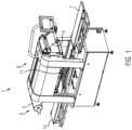
- the packaging machine 1 shows an example of a packaging machine 1 with a device 3 according to the invention for winding up a film 5.
- the packaging machine 1 is shown as a tray sealing machine. This has a feed belt 7 with which filled shells are conveyed to a closing station 9 . The shells are transferred to the closing station 9 with a gripper device 11 and closed there with a cover film 5 (foil) fed from above by sealing the cover film 5 on. The finished packs are transferred from the closing station 9 to a discharge belt 15 via the gripper system 11 .
- cover film 5 After the cover film 5 has been sealed on, areas of the cover film 5 corresponding to the packages or composite packaging are cut out of the web of cover film 5 in the sealing station 9 . A residual film lattice of the cover film 5 remains, which is wound up with the device 3 for winding up the film 5 .
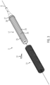
- the device 3 shows a schematic view of the device 3 for winding up the film 5.
- the device 3 comprises a receiving mandrel 17, which is arranged to be rotatable about an axis of rotation D by means of a drive device 19.
- a receiving sleeve 21 is attached to the receiving mandrel 17 .
- the receiving sleeve 21 rotates with the receiving mandrel 17, the film 5 being wound onto the receiving sleeve 21.
- the receiving sleeve 21 comprises a multiplicity of segments 23 which extend parallel to the axis of rotation D. Adjacent segments 23 are pivotally connected to one another, with the corresponding pivot axes S also running parallel to the axis of rotation D of the receiving mandrel 17 .
- the receiving mandrel 17 is designed as a rigid body which has engagement structures 25 .
- the substantially cylindrical receiving mandrel 17 comprises grooves extending parallel to its axis of rotation D, between which rib-shaped elevations are defined, which form the engagement structures 25 .
- the receiving sleeve 21 can be pushed onto the receiving mandrel 17 parallel to the axis of rotation D of the receiving mandrel 17 .
- a stop 27 (for example in the form of a grub screw) is provided on the receiving mandrel 17 and defines a possible end position of the receiving sleeve 21 when it is pushed onto the receiving mandrel 17 .
- the fuse comprises an elastic element 29 which is ring-shaped and extends around the outer circumference of the arbor 17 .
- the elastic element 29 can in particular be accommodated in a groove of the receiving mandrel 17 .
- the elastic element 29 lies between an outer circumference of the receiving mandrel 17 and an inner circumference of the receiving sleeve 21 and counteracts an axial sliding down of the receiving sleeve 21 from the receiving mandrel 17 .
- the securing device can also comprise a wedge system 31, which can have one or more wedges which, after the receiving sleeve 21 has been pushed onto the receiving mandrel 17, can be pushed at least partially between the receiving mandrel 17 and the receiving sleeve 21 in order to adjust the axial position of the To secure receiving sleeve 21 on the receiving mandrel 17.
- the resulting film roll can be pulled off the receiving mandrel 17 together with the receiving sleeve 21 .
- the wedge system 31 can first be removed.
- the receiving sleeve 21 can then be pulled off with the roll of film, if necessary by overcoming the retaining force of the elastic element 29 .
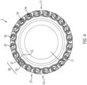
- the segments 23 of the receiving sleeve 21 are formed by link elements, each of which has two receiving openings 33 extending parallel to the axis of rotation D include. Adjacent segments 23 are nested along a circumference of receiving sleeve 21 such that corresponding openings 33 of adjacent segments 23 overlap and form a common receiving opening for bolts or rods 34 (only two shown) which pivotally connect adjacent segments 23 together.
- the receiving sleeve 21 comprises twenty segments 23. Due to the relatively high number of segments 23, the shape of the receiving sleeve 21 can be adapted relatively well to the shape of the receiving mandrel 17, in particular a substantially cylindrical shape. However, a different number of segments 23 would also be conceivable.
- the segments 23 are shaped on their inward-facing side in such a way that they each have inward-pointing bulges 35 and, compared to the bulges 35 , regions 37 that protrude less far inwards.
- This shape of the individual segments 23 results in an overall uneven inner circumference for the receiving sleeve 21 .
- Shape features 39 of the inner circumference of receiving sleeve 21 are thus formed by the shape of segments 23 .
- the engagement structures 25 of the receiving mandrel 17 are designed in such a way that they interact with the shaped features 39 of the inner circumference of the receiving sleeve 21 so that a rotation of the receiving mandrel 17 about the axis of rotation D causes the receiving sleeve 21 to rotate as well.
- the engagement structures 25 of the holding mandrel 17 are designed in the form of ribs for this purpose, which extend parallel to the axis of rotation D of the holding mandrel 17 .
- the bolts or rods 34 are preferably also provided in the openings 33 of the segments 23 of the receiving sleeve 21 with play. If the film 5 is now wound up by rotating the take-up mandrel 17, a radially inward-acting pressure is exerted from the outside on the take-up sleeve 21, so that it fits even better to the take-up mandrel 17 due to the play of the bolts or rods 34 in the openings 33 and whose engagement structures 25 applies, so that the power transmission between the arbor 17 and of the receiving sleeve 21 is improved.
- the segments 23 mutually stabilize one another as a result of the external pressure, so that the overall shape of the receiving sleeve 21 is stabilized. This ensures that the receiving sleeve 21 can still be pulled off the receiving mandrel 17 in the axial direction even after the film 5 has been wound up.
- FIG. 5 shows in to the view 4
- An analogous perspective shows an exemplary alternative embodiment of the receiving mandrel 17 and the receiving sleeve 21.
- the segments 23 of the receiving sleeve 21 are formed by flat plates extending parallel to the axis of rotation D of the receiving mandrel 17. Adjacent segments 23 in turn have overlapping openings 33 for receiving bolts or rods 34 so that the adjacent segments 23 are pivotally connected to each other.
- an inner circumference of the receiving sleeve 21 is in the form of a polygon. The corners of the polygon form features 39 of the inner circumference of the receiving sleeve 21 for force transmission between the receiving mandrel 17 and the receiving sleeve 21.
- the receiving mandrel 17 is equipped with a corresponding polygon-shaped circumference.
- the corners of this polygonal circumference form engagement structures 25 for engaging in the shaped features 39 of the receiving sleeve 21.
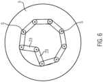
- 6 12 shows the receiving sleeve 21 of the embodiment figure 5 after the film 5 has been rolled up and the receiving sleeve 21 with the film roll has been pulled off the receiving mandrel 17. Due to the pivotability of adjacent segments 23 of the receiving sleeve 21, the receiving sleeve 21 can be converted into an unstable configuration in the pulled-off state, in which it can be removed from the interior of the film roll is. As in 6 shown, for this purpose segments 23 of the receiving sleeve 21 are pivoted inwards on a central axis of the receiving sleeve 21 . A removal of the receiving sleeve 21 is based on the same principle for the embodiment of Figures 2 to 4 possible.
Landscapes
- Winding Of Webs (AREA)
- Basic Packing Technique (AREA)
Claims (14)
- Dispositif (3) pour bobiner un film (5) sur une machine d'emballage (1), comprenant :un mandrin de réception (17) pouvant être entrainé en rotation autour d'un axe de rotation (D) ; etun manchon de réception (21) pour le film (5) à monter sur le manchon de réception (17), dans lequel le manchon de réception (21) est formé de segments (23) agencés côte à côte le long d'une circonférence du manchon de réception (21), dans lequel des segments voisins (23) sont reliés mutuellement de manière pivotante,dans lequel le mandrin de réception (17) est réalisé sous la forme d'un corps rigide avec des structures de mise en prise (25) qui sont configurées pour coopérer avec des caractéristiques de forme (39) d'une périphérie intérieure du manchon de réception (21) lorsque le manchon de réception (21) est monté sur le mandrin de réception (17), de sorte qu'une rotation du mandrin de réception (17) autour de l'axe de rotation (D) provoque une rotation simultanée du manchon de réception (21),dans lequel les structures de mise en prise (25) s'étendent parallèlement à l'axe de rotation (D), etdans lequel les structures de mise en prise (25) sont réalisées sous la forme de saillies et/ou de nervures.
- Dispositif selon la revendication 1, dans lequel des segments adjacents (23) du manchon de réception (21) sont reliés de manière pivotante autour d'axes de pivotement (S) s'étendant parallèlement à l'axe de rotation (D) dans l'état monté du manchon de réception (21).
- Dispositif selon l'une quelconque des revendications précédentes, dans lequel les structures de mise en prise (25) sont réparties de manière symétrique le long d'une périphérie du mandrin de réception (17).
- Dispositif selon l'une quelconque des revendications précédentes, dans lequel au moins quatre structures de mise en prise (25) sont prévues le long d'une périphérie du mandrin de réception (17).
- Dispositif selon l'une quelconque des revendications précédentes, dans lequel le nombre de structures de mise en prise (25) correspond au nombre de segments (23) du manchon de réception (21).
- Dispositif selon l'une quelconque des revendications précédentes, dans lequel les structures de mise en prise (25) du mandrin de réception (17) et les caractéristiques de forme (39) de la périphérie intérieure du manchon de réception (21) présentent des formes qui correspondent mutuellement.
- Dispositif selon l'une quelconque des revendications précédentes, dans lequel les caractéristiques de forme (39) de la périphérie intérieure du manchon de réception (21) avec lequel coopèrent les structures de mise en prise (25) du mandrin de réception (17) sont définies par l'agencement mutuel des segments (23) du manchon de réception (21).
- Dispositif selon l'une quelconque des revendications précédentes, dans lequel les caractéristiques de forme (39) de la périphérie intérieure du manchon de réception (21) avec lesquelles coopèrent les structures de mise en prise (25) du mandrin de réception (17) sont définies par la forme des segments individuels (23) du manchon de réception (21).
- Dispositif selon l'une quelconque des revendications précédentes, comprenant en outre une sécurité configurée pour sécuriser une position axiale du manchon de réception (21) sur le mandrin de réception (17).
- Dispositif selon la revendication 9, dans lequel la sécurité comprend un élément élastique (29) prévu sur le mandrin de réception (17), en particulier un joint torique, une bague en silicone ou une bague élastique, et/ou un système de clavette (31).
- Procédé pour bobiner un film (5) sur une machine d'emballage (1), comprenant les étapes consistant à :monter un manchon de réception (21), qui est formé de segments (23) agencés côte à côte le long d'une périphérie du manchon de réception (21), des segments voisins (23) étant reliés entre eux de manière pivotante, sur un mandrin de réception (17) réalisé sous la forme d'un corps rigide avec des structures de mise en prise (25), les structures de mise en prise (25) étant réalisées sous la forme de saillies et/ou de nervures ; etentraîner le mandrin de réception (17) pour une rotation autour d'un axe de rotation (D) par rapport auquel les structures de mise en prise (25) s'étendent parallèlement, dans lequel les structures de mise en prise (25) du mandrin de réception (17) coopèrent avec des caractéristiques de forme (39) d'une périphérie intérieure du manchon de réception (21) monté, de sorte que la rotation du mandrin de réception (17) autour de l'axe de rotation (D) provoque une rotation simultanée du manchon de réception (21), dans lequel le film (5) est bobiné sur le manchon de réception (21).
- Procédé selon la revendication 11, dans lequel une position axiale du manchon de réception (21) sur le mandrin de réception (17) est sécurisée à l'aide d'une sécurité.
- Procédé selon la revendication 12, dans lequel la sécurité comprend un élément élastique (29) prévu sur le mandrin de réception (17), en particulier un joint torique, une bague en silicone ou une bague élastique, ou un système de clavette (31).
- Procédé selon l'une quelconque des revendications 11 à 13, dans lequel le manchon de réception (21) est retiré du mandrin de réception (17) avec le film bobiné (5) et une configuration du manchon de réception (21) est modifiée par modification de la position mutuelle des segments (23) du manchon de réception (21) par pivotement de segments voisins (23), de telle sorte qu'il peut être retiré du rouleau de film bobiné.
Applications Claiming Priority (1)
| Application Number | Priority Date | Filing Date | Title |
|---|---|---|---|
| DE102019206153.2A DE102019206153A1 (de) | 2019-04-30 | 2019-04-30 | Vorrichtung und Verfahren zum Aufwickeln einer Folie an einer Verpackungsmaschine |
Publications (2)
| Publication Number | Publication Date |
|---|---|
| EP3733576A1 EP3733576A1 (fr) | 2020-11-04 |
| EP3733576B1 true EP3733576B1 (fr) | 2023-05-03 |
Family
ID=69770495
Family Applications (1)
| Application Number | Title | Priority Date | Filing Date |
|---|---|---|---|
| EP20160698.5A Active EP3733576B1 (fr) | 2019-04-30 | 2020-03-03 | Dispositif et procédé d'enroulement d'un film sur une machine d'emballage |
Country Status (5)
| Country | Link |
|---|---|
| US (1) | US11254533B2 (fr) |
| EP (1) | EP3733576B1 (fr) |
| CN (1) | CN212315040U (fr) |
| DE (1) | DE102019206153A1 (fr) |
| ES (1) | ES2949673T3 (fr) |
Family Cites Families (14)
| Publication number | Priority date | Publication date | Assignee | Title |
|---|---|---|---|---|
| US1832590A (en) * | 1929-02-27 | 1931-11-17 | Foxcase Corp | Reel |
| US2585159A (en) * | 1946-06-17 | 1952-02-12 | James C Morley | Cable reel |
| US2973160A (en) * | 1959-01-26 | 1961-02-28 | Mercury Engineering Corp | Expandable mandrel for web rewinders |
| US3355121A (en) * | 1966-10-13 | 1967-11-28 | Sonoco Products Co | Expansible chuck for tubular core |
| US3396918A (en) * | 1967-01-09 | 1968-08-13 | Goodyear Tire & Rubber | Expandable adapter |
| AU778927B2 (en) * | 2000-02-24 | 2004-12-23 | Viscount Plastics (Australia) Pty Ltd | Collapsible reel assembly |
| AU780665B2 (en) * | 2000-12-07 | 2005-04-07 | Viscount Plastics (Australia) Pty Ltd | Locking plate for a collapsible reel assembly |
| GB0204085D0 (en) * | 2002-02-21 | 2002-04-10 | Cg Automation Ltd | Collapsible mandrel |
| US20040113011A1 (en) * | 2002-12-17 | 2004-06-17 | Place James S. | Reusable collapsible core |
| US20050145746A1 (en) * | 2002-12-17 | 2005-07-07 | Place James S. | Reusable collapsible core |
| US7036766B2 (en) * | 2002-12-17 | 2006-05-02 | Maximum Production Solutions, Inc. | Reusable collapsible core |
| TWM330196U (en) * | 2007-05-08 | 2008-04-11 | Tsc Auto Id Technology Co Ltd | Carbon ribbon for tab printer and paper winding reel |
| US10752464B2 (en) * | 2015-08-04 | 2020-08-25 | Nine Ip Limited | Fabric roll up core for carrying sheet material |
| EP3214031A1 (fr) * | 2016-03-02 | 2017-09-06 | MULTIVAC Sepp Haggenmüller SE & Co. KG | Manchon de reception |
-
2019
- 2019-04-30 DE DE102019206153.2A patent/DE102019206153A1/de active Pending
-
2020
- 2020-03-03 ES ES20160698T patent/ES2949673T3/es active Active
- 2020-03-03 EP EP20160698.5A patent/EP3733576B1/fr active Active
- 2020-04-27 CN CN202020659932.8U patent/CN212315040U/zh active Active
- 2020-04-29 US US15/929,380 patent/US11254533B2/en active Active
Also Published As
| Publication number | Publication date |
|---|---|
| US11254533B2 (en) | 2022-02-22 |
| ES2949673T3 (es) | 2023-10-02 |
| CN212315040U (zh) | 2021-01-08 |
| DE102019206153A1 (de) | 2020-11-05 |
| US20200346884A1 (en) | 2020-11-05 |
| EP3733576A1 (fr) | 2020-11-04 |
Similar Documents
| Publication | Publication Date | Title |
|---|---|---|
| EP3800020A1 (fr) | Dispositif et procédé de fabrication d'une bague de sécurité sur un capuchon de fermeture pour un récipient | |
| DE3045095A1 (de) | Vorrichtung zum abstreifen von abfallstuecken von zuschnitten | |
| DE102010039803A1 (de) | Blasform | |
| DE2304092A1 (de) | Einrichtung zum laengsschneiden schmaler streifen | |
| EP2049404B1 (fr) | Cylindre de transport, notamment cylindre de coupe, pour une étiqueteuse | |
| DE202017105406U1 (de) | Etikettieraggregat und Aufnahmedorn für ein Ettiketieraggregat | |
| DE19716628C2 (de) | Verfahren und Vorrichtung zum Querfalzen von Signaturen | |
| EP2567901B1 (fr) | Mandrin d'élargissement destiné à élargir un manchon d'étiquetage | |
| EP0602593B1 (fr) | Dispositif pour la coupe d'un produit plat, en particulier d'un produit imprimé multi-couches | |
| EP0602594B1 (fr) | Dispositif pour couper un produit plat, en particulier un produit imprimé multi-couches | |
| DE2757202C2 (fr) | ||
| EP2942303B1 (fr) | Enrouleuse pour un distributeur d'étiquettes | |
| EP2828061B1 (fr) | Appareil de thermoformage | |
| DE2458869A1 (de) | Vorrichtung zum schlitzen von rollenmaterial mit einer selbstbeschickungseinrichtung | |
| EP1719725A2 (fr) | Tête de serrage pour une refendeuse-bobineuse | |
| EP1509468B1 (fr) | Element d'entrainement | |
| CH677900A5 (fr) | ||
| DE69305029T2 (de) | Vorrichtung und Verfahren zum Einhalsen von Dosen mittels Fliessdrücken | |
| EP3733576A1 (fr) | Dispositif et procédé d'enroulement d'un film sur une machine d'emballage | |
| EP2903807B1 (fr) | Mécanisme de pliage pour les flancs d'un pneumatique | |
| EP2499048B1 (fr) | Procede et dispositif de fabrication des sacs triangulaire d'emballage | |
| WO2009138067A1 (fr) | Dispositif de pliage présentant des arbres d'outils de coupe ou analogues montés en amont ou en aval | |
| EP2998258B1 (fr) | Dispositif d'enroulement de feuille pour une machine d'emballage | |
| DE4335580A1 (de) | Vorrichtung zum Trennen einer mehrfach hohen Dosenzarge | |
| DE10224839B4 (de) | Spanndorn |
Legal Events
| Date | Code | Title | Description |
|---|---|---|---|
| PUAI | Public reference made under article 153(3) epc to a published international application that has entered the european phase |
Free format text: ORIGINAL CODE: 0009012 |
|
| STAA | Information on the status of an ep patent application or granted ep patent |
Free format text: STATUS: THE APPLICATION HAS BEEN PUBLISHED |
|
| AK | Designated contracting states |
Kind code of ref document: A1 Designated state(s): AL AT BE BG CH CY CZ DE DK EE ES FI FR GB GR HR HU IE IS IT LI LT LU LV MC MK MT NL NO PL PT RO RS SE SI SK SM TR |
|
| AX | Request for extension of the european patent |
Extension state: BA ME |
|
| STAA | Information on the status of an ep patent application or granted ep patent |
Free format text: STATUS: REQUEST FOR EXAMINATION WAS MADE |
|
| 17P | Request for examination filed |
Effective date: 20210504 |
|
| RBV | Designated contracting states (corrected) |
Designated state(s): AL AT BE BG CH CY CZ DE DK EE ES FI FR GB GR HR HU IE IS IT LI LT LU LV MC MK MT NL NO PL PT RO RS SE SI SK SM TR |
|
| RIC1 | Information provided on ipc code assigned before grant |
Ipc: B65H 75/24 20060101ALI20220913BHEP Ipc: B65H 75/22 20060101ALI20220913BHEP Ipc: B65H 75/10 20060101AFI20220913BHEP |
|
| GRAP | Despatch of communication of intention to grant a patent |
Free format text: ORIGINAL CODE: EPIDOSNIGR1 |
|
| STAA | Information on the status of an ep patent application or granted ep patent |
Free format text: STATUS: GRANT OF PATENT IS INTENDED |
|
| INTG | Intention to grant announced |
Effective date: 20221102 |
|
| GRAS | Grant fee paid |
Free format text: ORIGINAL CODE: EPIDOSNIGR3 |
|
| GRAA | (expected) grant |
Free format text: ORIGINAL CODE: 0009210 |
|
| STAA | Information on the status of an ep patent application or granted ep patent |
Free format text: STATUS: THE PATENT HAS BEEN GRANTED |
|
| AK | Designated contracting states |
Kind code of ref document: B1 Designated state(s): AL AT BE BG CH CY CZ DE DK EE ES FI FR GB GR HR HU IE IS IT LI LT LU LV MC MK MT NL NO PL PT RO RS SE SI SK SM TR |
|
| REG | Reference to a national code |
Ref country code: GB Ref legal event code: FG4D Free format text: NOT ENGLISH |
|
| REG | Reference to a national code |
Ref country code: DE Ref legal event code: R096 Ref document number: 502020003128 Country of ref document: DE |
|
| REG | Reference to a national code |
Ref country code: AT Ref legal event code: REF Ref document number: 1564450 Country of ref document: AT Kind code of ref document: T Effective date: 20230515 Ref country code: CH Ref legal event code: EP |
|
| REG | Reference to a national code |
Ref country code: IE Ref legal event code: FG4D Free format text: LANGUAGE OF EP DOCUMENT: GERMAN |
|
| REG | Reference to a national code |
Ref country code: NL Ref legal event code: FP |
|
| REG | Reference to a national code |
Ref country code: LT Ref legal event code: MG9D |
|
| P01 | Opt-out of the competence of the unified patent court (upc) registered |
Effective date: 20230801 |
|
| REG | Reference to a national code |
Ref country code: ES Ref legal event code: FG2A Ref document number: 2949673 Country of ref document: ES Kind code of ref document: T3 Effective date: 20231002 |
|
| PG25 | Lapsed in a contracting state [announced via postgrant information from national office to epo] |
Ref country code: SE Free format text: LAPSE BECAUSE OF FAILURE TO SUBMIT A TRANSLATION OF THE DESCRIPTION OR TO PAY THE FEE WITHIN THE PRESCRIBED TIME-LIMIT Effective date: 20230503 Ref country code: PT Free format text: LAPSE BECAUSE OF FAILURE TO SUBMIT A TRANSLATION OF THE DESCRIPTION OR TO PAY THE FEE WITHIN THE PRESCRIBED TIME-LIMIT Effective date: 20230904 Ref country code: NO Free format text: LAPSE BECAUSE OF FAILURE TO SUBMIT A TRANSLATION OF THE DESCRIPTION OR TO PAY THE FEE WITHIN THE PRESCRIBED TIME-LIMIT Effective date: 20230803 |
|
| PG25 | Lapsed in a contracting state [announced via postgrant information from national office to epo] |
Ref country code: RS Free format text: LAPSE BECAUSE OF FAILURE TO SUBMIT A TRANSLATION OF THE DESCRIPTION OR TO PAY THE FEE WITHIN THE PRESCRIBED TIME-LIMIT Effective date: 20230503 Ref country code: PL Free format text: LAPSE BECAUSE OF FAILURE TO SUBMIT A TRANSLATION OF THE DESCRIPTION OR TO PAY THE FEE WITHIN THE PRESCRIBED TIME-LIMIT Effective date: 20230503 Ref country code: LV Free format text: LAPSE BECAUSE OF FAILURE TO SUBMIT A TRANSLATION OF THE DESCRIPTION OR TO PAY THE FEE WITHIN THE PRESCRIBED TIME-LIMIT Effective date: 20230503 Ref country code: LT Free format text: LAPSE BECAUSE OF FAILURE TO SUBMIT A TRANSLATION OF THE DESCRIPTION OR TO PAY THE FEE WITHIN THE PRESCRIBED TIME-LIMIT Effective date: 20230503 Ref country code: IS Free format text: LAPSE BECAUSE OF FAILURE TO SUBMIT A TRANSLATION OF THE DESCRIPTION OR TO PAY THE FEE WITHIN THE PRESCRIBED TIME-LIMIT Effective date: 20230903 Ref country code: HR Free format text: LAPSE BECAUSE OF FAILURE TO SUBMIT A TRANSLATION OF THE DESCRIPTION OR TO PAY THE FEE WITHIN THE PRESCRIBED TIME-LIMIT Effective date: 20230503 Ref country code: GR Free format text: LAPSE BECAUSE OF FAILURE TO SUBMIT A TRANSLATION OF THE DESCRIPTION OR TO PAY THE FEE WITHIN THE PRESCRIBED TIME-LIMIT Effective date: 20230804 |
|
| PG25 | Lapsed in a contracting state [announced via postgrant information from national office to epo] |
Ref country code: FI Free format text: LAPSE BECAUSE OF FAILURE TO SUBMIT A TRANSLATION OF THE DESCRIPTION OR TO PAY THE FEE WITHIN THE PRESCRIBED TIME-LIMIT Effective date: 20230503 |
|
| PG25 | Lapsed in a contracting state [announced via postgrant information from national office to epo] |
Ref country code: SK Free format text: LAPSE BECAUSE OF FAILURE TO SUBMIT A TRANSLATION OF THE DESCRIPTION OR TO PAY THE FEE WITHIN THE PRESCRIBED TIME-LIMIT Effective date: 20230503 |
|
| PG25 | Lapsed in a contracting state [announced via postgrant information from national office to epo] |
Ref country code: SM Free format text: LAPSE BECAUSE OF FAILURE TO SUBMIT A TRANSLATION OF THE DESCRIPTION OR TO PAY THE FEE WITHIN THE PRESCRIBED TIME-LIMIT Effective date: 20230503 Ref country code: SK Free format text: LAPSE BECAUSE OF FAILURE TO SUBMIT A TRANSLATION OF THE DESCRIPTION OR TO PAY THE FEE WITHIN THE PRESCRIBED TIME-LIMIT Effective date: 20230503 Ref country code: RO Free format text: LAPSE BECAUSE OF FAILURE TO SUBMIT A TRANSLATION OF THE DESCRIPTION OR TO PAY THE FEE WITHIN THE PRESCRIBED TIME-LIMIT Effective date: 20230503 Ref country code: EE Free format text: LAPSE BECAUSE OF FAILURE TO SUBMIT A TRANSLATION OF THE DESCRIPTION OR TO PAY THE FEE WITHIN THE PRESCRIBED TIME-LIMIT Effective date: 20230503 Ref country code: DK Free format text: LAPSE BECAUSE OF FAILURE TO SUBMIT A TRANSLATION OF THE DESCRIPTION OR TO PAY THE FEE WITHIN THE PRESCRIBED TIME-LIMIT Effective date: 20230503 Ref country code: CZ Free format text: LAPSE BECAUSE OF FAILURE TO SUBMIT A TRANSLATION OF THE DESCRIPTION OR TO PAY THE FEE WITHIN THE PRESCRIBED TIME-LIMIT Effective date: 20230503 |
|
| REG | Reference to a national code |
Ref country code: DE Ref legal event code: R097 Ref document number: 502020003128 Country of ref document: DE |
|
| PLBE | No opposition filed within time limit |
Free format text: ORIGINAL CODE: 0009261 |
|
| STAA | Information on the status of an ep patent application or granted ep patent |
Free format text: STATUS: NO OPPOSITION FILED WITHIN TIME LIMIT |
|
| 26N | No opposition filed |
Effective date: 20240206 |
|
| PG25 | Lapsed in a contracting state [announced via postgrant information from national office to epo] |
Ref country code: SI Free format text: LAPSE BECAUSE OF FAILURE TO SUBMIT A TRANSLATION OF THE DESCRIPTION OR TO PAY THE FEE WITHIN THE PRESCRIBED TIME-LIMIT Effective date: 20230503 |
|
| PG25 | Lapsed in a contracting state [announced via postgrant information from national office to epo] |
Ref country code: SI Free format text: LAPSE BECAUSE OF FAILURE TO SUBMIT A TRANSLATION OF THE DESCRIPTION OR TO PAY THE FEE WITHIN THE PRESCRIBED TIME-LIMIT Effective date: 20230503 |
|
| PG25 | Lapsed in a contracting state [announced via postgrant information from national office to epo] |
Ref country code: BG Free format text: LAPSE BECAUSE OF FAILURE TO SUBMIT A TRANSLATION OF THE DESCRIPTION OR TO PAY THE FEE WITHIN THE PRESCRIBED TIME-LIMIT Effective date: 20230503 |
|
| PG25 | Lapsed in a contracting state [announced via postgrant information from national office to epo] |
Ref country code: LU Free format text: LAPSE BECAUSE OF NON-PAYMENT OF DUE FEES Effective date: 20240303 |
|
| PG25 | Lapsed in a contracting state [announced via postgrant information from national office to epo] |
Ref country code: MC Free format text: LAPSE BECAUSE OF FAILURE TO SUBMIT A TRANSLATION OF THE DESCRIPTION OR TO PAY THE FEE WITHIN THE PRESCRIBED TIME-LIMIT Effective date: 20230503 |
|
| PG25 | Lapsed in a contracting state [announced via postgrant information from national office to epo] |
Ref country code: MC Free format text: LAPSE BECAUSE OF FAILURE TO SUBMIT A TRANSLATION OF THE DESCRIPTION OR TO PAY THE FEE WITHIN THE PRESCRIBED TIME-LIMIT Effective date: 20230503 Ref country code: LU Free format text: LAPSE BECAUSE OF NON-PAYMENT OF DUE FEES Effective date: 20240303 Ref country code: BG Free format text: LAPSE BECAUSE OF FAILURE TO SUBMIT A TRANSLATION OF THE DESCRIPTION OR TO PAY THE FEE WITHIN THE PRESCRIBED TIME-LIMIT Effective date: 20230503 |
|
| REG | Reference to a national code |
Ref country code: BE Ref legal event code: MM Effective date: 20240331 |
|
| PG25 | Lapsed in a contracting state [announced via postgrant information from national office to epo] |
Ref country code: BE Free format text: LAPSE BECAUSE OF NON-PAYMENT OF DUE FEES Effective date: 20240331 |
|
| PG25 | Lapsed in a contracting state [announced via postgrant information from national office to epo] |
Ref country code: IE Free format text: LAPSE BECAUSE OF NON-PAYMENT OF DUE FEES Effective date: 20240303 |
|
| PG25 | Lapsed in a contracting state [announced via postgrant information from national office to epo] |
Ref country code: IE Free format text: LAPSE BECAUSE OF NON-PAYMENT OF DUE FEES Effective date: 20240303 Ref country code: BE Free format text: LAPSE BECAUSE OF NON-PAYMENT OF DUE FEES Effective date: 20240331 |
|
| PGFP | Annual fee paid to national office [announced via postgrant information from national office to epo] |
Ref country code: AT Payment date: 20250417 Year of fee payment: 5 |
|
| PGFP | Annual fee paid to national office [announced via postgrant information from national office to epo] |
Ref country code: ES Payment date: 20250416 Year of fee payment: 6 |
|
| PGFP | Annual fee paid to national office [announced via postgrant information from national office to epo] |
Ref country code: IT Payment date: 20250331 Year of fee payment: 6 |
|
| PGFP | Annual fee paid to national office [announced via postgrant information from national office to epo] |
Ref country code: CH Payment date: 20250401 Year of fee payment: 6 |
|
| P04 | Withdrawal of opt-out of the competence of the unified patent court (upc) registered |
Free format text: CASE NUMBER: APP_30717/2025 Effective date: 20250626 |
|
| PG25 | Lapsed in a contracting state [announced via postgrant information from national office to epo] |
Ref country code: CY Free format text: LAPSE BECAUSE OF FAILURE TO SUBMIT A TRANSLATION OF THE DESCRIPTION OR TO PAY THE FEE WITHIN THE PRESCRIBED TIME-LIMIT; INVALID AB INITIO Effective date: 20200303 |
|
| PG25 | Lapsed in a contracting state [announced via postgrant information from national office to epo] |
Ref country code: HU Free format text: LAPSE BECAUSE OF FAILURE TO SUBMIT A TRANSLATION OF THE DESCRIPTION OR TO PAY THE FEE WITHIN THE PRESCRIBED TIME-LIMIT; INVALID AB INITIO Effective date: 20200303 |
|
| PG25 | Lapsed in a contracting state [announced via postgrant information from national office to epo] |
Ref country code: TR Free format text: LAPSE BECAUSE OF FAILURE TO SUBMIT A TRANSLATION OF THE DESCRIPTION OR TO PAY THE FEE WITHIN THE PRESCRIBED TIME-LIMIT Effective date: 20230503 |
|
| REG | Reference to a national code |
Ref country code: CH Ref legal event code: U11 Free format text: ST27 STATUS EVENT CODE: U-0-0-U10-U11 (AS PROVIDED BY THE NATIONAL OFFICE) Effective date: 20260401 |
|
| PGFP | Annual fee paid to national office [announced via postgrant information from national office to epo] |
Ref country code: GB Payment date: 20260324 Year of fee payment: 7 |
|
| PGFP | Annual fee paid to national office [announced via postgrant information from national office to epo] |
Ref country code: DE Payment date: 20260320 Year of fee payment: 7 |
|
| PGFP | Annual fee paid to national office [announced via postgrant information from national office to epo] |
Ref country code: NL Payment date: 20260323 Year of fee payment: 7 |
|
| PGFP | Annual fee paid to national office [announced via postgrant information from national office to epo] |
Ref country code: FR Payment date: 20260324 Year of fee payment: 7 |