EP3733603B1 - Verfahren zur herstellung von hohlen kieselsäureteilchen - Google Patents
Verfahren zur herstellung von hohlen kieselsäureteilchen Download PDFInfo
- Publication number
- EP3733603B1 EP3733603B1 EP18895458.0A EP18895458A EP3733603B1 EP 3733603 B1 EP3733603 B1 EP 3733603B1 EP 18895458 A EP18895458 A EP 18895458A EP 3733603 B1 EP3733603 B1 EP 3733603B1
- Authority
- EP
- European Patent Office
- Prior art keywords
- hollow silica
- silica
- oil
- emulsion
- silica particles
- Prior art date
- Legal status (The legal status is an assumption and is not a legal conclusion. Google has not performed a legal analysis and makes no representation as to the accuracy of the status listed.)
- Active
Links
Images

Classifications
-
- C—CHEMISTRY; METALLURGY
- C01—INORGANIC CHEMISTRY
- C01B—NON-METALLIC ELEMENTS; COMPOUNDS THEREOF; METALLOIDS OR COMPOUNDS THEREOF NOT COVERED BY SUBCLASS C01C
- C01B33/00—Silicon; Compounds thereof
- C01B33/113—Silicon oxides; Hydrates thereof
- C01B33/12—Silica; Hydrates thereof, e.g. lepidoic silicic acid
- C01B33/18—Preparation of finely divided silica neither in sol nor in gel form; After-treatment thereof
- C01B33/187—Preparation of finely divided silica neither in sol nor in gel form; After-treatment thereof by acidic treatment of silicates
- C01B33/193—Preparation of finely divided silica neither in sol nor in gel form; After-treatment thereof by acidic treatment of silicates of aqueous solutions of silicates
-
- B—PERFORMING OPERATIONS; TRANSPORTING
- B01—PHYSICAL OR CHEMICAL PROCESSES OR APPARATUS IN GENERAL
- B01J—CHEMICAL OR PHYSICAL PROCESSES, e.g. CATALYSIS OR COLLOID CHEMISTRY; THEIR RELEVANT APPARATUS
- B01J13/00—Colloid chemistry, e.g. the production of colloidal materials or their solutions, not otherwise provided for; Making microcapsules or microballoons
- B01J13/02—Making microcapsules or microballoons
- B01J13/06—Making microcapsules or microballoons by phase separation
- B01J13/08—Simple coacervation, i.e. addition of highly hydrophilic material
-
- B—PERFORMING OPERATIONS; TRANSPORTING
- B01—PHYSICAL OR CHEMICAL PROCESSES OR APPARATUS IN GENERAL
- B01J—CHEMICAL OR PHYSICAL PROCESSES, e.g. CATALYSIS OR COLLOID CHEMISTRY; THEIR RELEVANT APPARATUS
- B01J13/00—Colloid chemistry, e.g. the production of colloidal materials or their solutions, not otherwise provided for; Making microcapsules or microballoons
- B01J13/02—Making microcapsules or microballoons
- B01J13/06—Making microcapsules or microballoons by phase separation
- B01J13/14—Polymerisation; cross-linking
-
- B—PERFORMING OPERATIONS; TRANSPORTING
- B82—NANOTECHNOLOGY
- B82Y—SPECIFIC USES OR APPLICATIONS OF NANOSTRUCTURES; MEASUREMENT OR ANALYSIS OF NANOSTRUCTURES; MANUFACTURE OR TREATMENT OF NANOSTRUCTURES
- B82Y40/00—Manufacture or treatment of nanostructures
-
- C—CHEMISTRY; METALLURGY
- C01—INORGANIC CHEMISTRY
- C01B—NON-METALLIC ELEMENTS; COMPOUNDS THEREOF; METALLOIDS OR COMPOUNDS THEREOF NOT COVERED BY SUBCLASS C01C
- C01B33/00—Silicon; Compounds thereof
- C01B33/113—Silicon oxides; Hydrates thereof
- C01B33/12—Silica; Hydrates thereof, e.g. lepidoic silicic acid
- C01B33/18—Preparation of finely divided silica neither in sol nor in gel form; After-treatment thereof
- C01B33/187—Preparation of finely divided silica neither in sol nor in gel form; After-treatment thereof by acidic treatment of silicates
-
- C—CHEMISTRY; METALLURGY
- C01—INORGANIC CHEMISTRY
- C01P—INDEXING SCHEME RELATING TO STRUCTURAL AND PHYSICAL ASPECTS OF SOLID INORGANIC COMPOUNDS
- C01P2004/00—Particle morphology
- C01P2004/01—Particle morphology depicted by an image
- C01P2004/03—Particle morphology depicted by an image obtained by SEM
-
- C—CHEMISTRY; METALLURGY
- C01—INORGANIC CHEMISTRY
- C01P—INDEXING SCHEME RELATING TO STRUCTURAL AND PHYSICAL ASPECTS OF SOLID INORGANIC COMPOUNDS
- C01P2004/00—Particle morphology
- C01P2004/01—Particle morphology depicted by an image
- C01P2004/04—Particle morphology depicted by an image obtained by TEM, STEM, STM or AFM
-
- C—CHEMISTRY; METALLURGY
- C01—INORGANIC CHEMISTRY
- C01P—INDEXING SCHEME RELATING TO STRUCTURAL AND PHYSICAL ASPECTS OF SOLID INORGANIC COMPOUNDS
- C01P2004/00—Particle morphology
- C01P2004/30—Particle morphology extending in three dimensions
- C01P2004/32—Spheres
- C01P2004/34—Spheres hollow
-
- C—CHEMISTRY; METALLURGY
- C01—INORGANIC CHEMISTRY
- C01P—INDEXING SCHEME RELATING TO STRUCTURAL AND PHYSICAL ASPECTS OF SOLID INORGANIC COMPOUNDS
- C01P2004/00—Particle morphology
- C01P2004/60—Particles characterised by their size
- C01P2004/61—Micrometer sized, i.e. from 1-100 micrometer
-
- C—CHEMISTRY; METALLURGY
- C01—INORGANIC CHEMISTRY
- C01P—INDEXING SCHEME RELATING TO STRUCTURAL AND PHYSICAL ASPECTS OF SOLID INORGANIC COMPOUNDS
- C01P2004/00—Particle morphology
- C01P2004/60—Particles characterised by their size
- C01P2004/62—Submicrometer sized, i.e. from 0.1-1 micrometer
-
- C—CHEMISTRY; METALLURGY
- C01—INORGANIC CHEMISTRY
- C01P—INDEXING SCHEME RELATING TO STRUCTURAL AND PHYSICAL ASPECTS OF SOLID INORGANIC COMPOUNDS
- C01P2004/00—Particle morphology
- C01P2004/60—Particles characterised by their size
- C01P2004/64—Nanometer sized, i.e. from 1-100 nanometer
-
- C—CHEMISTRY; METALLURGY
- C01—INORGANIC CHEMISTRY
- C01P—INDEXING SCHEME RELATING TO STRUCTURAL AND PHYSICAL ASPECTS OF SOLID INORGANIC COMPOUNDS
- C01P2006/00—Physical properties of inorganic compounds
- C01P2006/12—Surface area
-
- C—CHEMISTRY; METALLURGY
- C01—INORGANIC CHEMISTRY
- C01P—INDEXING SCHEME RELATING TO STRUCTURAL AND PHYSICAL ASPECTS OF SOLID INORGANIC COMPOUNDS
- C01P2006/00—Physical properties of inorganic compounds
- C01P2006/80—Compositional purity
Definitions
- the present invention relates to a method for producing hollow silica particles.
- Hollow silica particles each comprising a shell layer formed of silica and an empty space in the shell layer.
- Hollow silica particles are, due to their variety of the particle sizes, the pore structures of the shell layer and the surface physical properties, widely used for a catalyst, a catalyst carrier, a cosmetic pigment, a resin filler, an adsorbent, a desiccating agent, a heat insulting material, a coating material, drug delivery system, an optical filter, etc. Further, they are useful also as an antireflection coating film material due to their low refractive index by their hollow shape.
- an oil-in-water emulsion in which an oil phase is dispersed in an aqueous phase is prepared, a silica material is deposited on oil droplets to prepare oil core/silica shell particles, and the oil droplet components are removed from the particles to obtain hollow silica particles. Since the particles are prepared from an emulsion, hollow silica particles having a particle size of from about several tens nm to 10 ⁇ m can be formed.
- hollow silica particles having small particle sizes have a thin silica shell layer, and thus the particle strength decreases, and the particles may be broken during use or during storage. If the shell layer has low strength, the particles may be broken when mixed with other material such as ceramic raw material. Further, if the shell layer is porous, the hollow structure in the inside may not be maintained when the particles are mixed with e.g. a solvent.
- Patent Document 1 an initial container bottom content containing water, sodium chloride, precipitated calcium carbonate and sodium silicate is stirred at pH 9, and then an aqueous sodium silicate solution and an aqueous sulfuric acid solution are added, followed by aging, filtration and drying to obtain dry particles, and the dry particles are treated with concentrated hydrochloric acid to remove calcium carbonate thereby to produce hollow silica particles.
- Patent Document 2 proposes hollow silica microcapsules having an average pore diameter of from 1.6 to 10 nm.
- Patent Document 2 proposes a method in which a W/O emulsion or an O/W/O emulsion containing a silicate of an alkali metal in an aqueous phase is obtained, a precipitant is added to the emulsion to form hollow silica microcapsules, followed by predetermined washing with water, drying and baking, and further the baked microcapsules are formed into mesoporous to produce hollow silica microcapsules.
- Non-Patent Document 1 proposes a method in which an emulsion using a poly(ethylene oxide)/poly(propylene oxide)/poly(ethylene oxide) block copolymer and sodium silicate are combined to prepare hollow silica particles.
- Non-Patent Document 1 ethanol having trimethylbenzene dissolved therein is added to an aqueous solution having the block copolymer added, to obtain an emulsion, to which an aqueous sodium silicate solution is added to adjust the pH to 5.2, followed by aging, and the resulting white powder is isolated, dried and baked to prepare hollow silica particles.
- hollow silica particles having an average diameter of at most about 1 ⁇ m and having a BET specific surface area of about 426 m 2 /g are obtained.
- Non-Patent Document 1 Qianyao Sun et al, "The Formation of Well-Defined Hollow Silica Spheres with Multilamellar Shell Structure", Advanced Materials, 2003, 15, No.13, July 4 .
- WO 2011/091285 A1 describes ceramic encapsulation by use of one or more silanes to template oil in water emulsion.
- EP 3 078 415 A1 describes a process for producing microcapsules capable of retaining an organic compound as an active ingredient such as fragrance materials therein over a long period of time.
- the core particles are formed of calcium carbonate
- the emulsion is alkalified to deposit the silica material on the core particles.
- the particle size and the shape of the obtainable hollow particles are restricted by the particle size and the shape of the solid calcium carbonate particles which are the core particles.
- the shell layer may have voids, and thus the shell layer cannot sufficiently be densified, and the strength of the shell layer may decrease by the acid treatment.
- Patent Document 1 a liquid material such as a vegetable oil is mentioned as another example of the core particles, however, the silica material may not sufficiently be deposited on the core particles formed of the liquid material under alkaline conditions.
- Hollow silica obtained from a W/O emulsion as in Patent Document 2 are not particles having an apparent empty space in their hollow space but particles of which the silica density is gradually decreased from the outermost shell toward the center, since the hollow silica is formed of droplets of an aqueous phase containing an alkali metal silicate.
- hollow silica obtained from a W/O/W emulsion are such that the oil droplets at the center becomes the hollow space, and the silica material contained in the aqueous phase as the intermediate layer forms a shell layer.
- the shell layer which is formed of the aqueous phase in the intermediate layer, can hardly be densified.
- Non-Patent Document 1 sodium silicate is deposited on oil droplets of an oil-in-water emulsion under acidic conditions, followed by aging, and then the resulting white powder is isolated.
- the shell layer of the obtained hollow silica particles cannot sufficiently be densified, and the hollow silica particles tend to be inferior in strength.
- an object of the present invention is to provide hollow silica particles having a dense silica shell layer.
- hollow silica particles having a dense silica shell layer can be provided.
- the method for producing hollow silica particles of the present invention is a method for producing hollow silica particles, which comprises:
- hollow silica particles having a dense silica shell layer can be obtained. Since the shell layer is dense, the particle strength is increased, and their shape can be maintained even when mixed with other material. Further, since the shell layer is dense, the solvent and foreign substances from outside are less likely to invade the hollow portion in the inside.
- silica material is not limited, and for example, even an alkali metal silicate may be used to provide hollow silica particles having a dense silica shell layer.
- an oil-in-water emulsion containing an aqueous phase, an oil phase and a surfactant is used.
- This oil-in-water emulsion is an emulsion having an oil phase dispersed in water, and when a silica material is added to the emulsion, the silica material is deposited on the oil droplets, whereby oil core/silica shell particles can be formed.
- the oil-in-water emulsion may sometimes be referred to simply as an emulsion.
- a dispersion having oil core/silica shell particles dispersed, formed by adding the first silica material and not having the second silica material added yet, and a dispersion having oil core/silica shell particles dispersed, having the second silica material added may also be sometimes referred to as an emulsion.
- the latter dispersion having oil core/silica shell particles dispersed, having the second silica material added may be the same as the hollow silica precursor dispersion.
- the aqueous phase of the emulsion contains mainly water as a solvent.
- the aqueous phase may further contain a water-soluble organic liquid or an additive such as a water-soluble resin.
- the proportion of the water in the aqueous phase is from 90 to 100 mass%.
- the oil phase of the emulsion preferably contains a water-insoluble organic liquid which is incompatible with the aqueous phase component. This organic liquid forms droplets in the emulsion thereby to form an oil core portion of the hollow silica precursor.
- the organic liquid may, for example, be an aliphatic hydrocarbon such as n-hexane, isohexane, n-heptane, isoheptane, n-octane, isooctane, n-nonane, isononane, n-pentane, isopentane, n-decane, isodecane, n-dodecane, isododecane or pentadecane, a paraffin base oil which is a mixture thereof, an alicyclic hydrocarbon such as cyclopentane, cyclohexane or cyclohexene, a naphthene base oil which is a mixture thereof, an aromatic hydrocarbon such as benzene, toluene, xylene, ethylbenzene, propylbenzene, cumene, mesitylene, tetralin or styrene, an ether
- a polyoxyalkylene glycol to be a hydrophobic liquid at the shell forming reaction temperature may also be used.
- polypropylene glycol molecular weight: at least 1,000
- a polyoxyethylene/polyoxypropylene block copolymer having a proportion of oxyethylene units of less than 20 mass% and a cloudy point (1 mass% aqueous solution) of at most 40°C, preferably at most 20°C may be mentioned.
- a polyoxypropylene/polyoxyethylene/polyoxypropylene type block copolymer is preferably used.
- the organic liquid is preferably a C 8-16 , particularly C 9-12 hydrocarbon.
- the organic liquid is selected comprehensively considering the workability, the safety against fire, separation property of the hollow silica precursor and the organic liquid, the shape of the hollow silica particles, solubility of the organic liquid in water, etc.
- the C 8-16 hydrocarbon may be any of linear, branched and cyclic hydrocarbons so long as it is chemically stable, or may be a mixture of hydrocarbons differing in the number of carbon atoms.
- the hydrocarbon is preferably a saturated hydrocarbon, more preferably a linear saturated hydrocarbon.
- the organic liquid is preferably one having a flash point of from 20 to 90°C, more preferably from 30 to 80°C. If an organic liquid having a flash point of less than 20°C is used, countermeasures in the work environment are required for fire control due to too low flash point. Further, if an organic liquid having a flash point higher than 90°C is used, due to small volatility, the amount of the organic liquid deposited on the obtained hollow silica particles may be large.
- the emulsion contains a surfactant so as to improve emulsification stability.
- the surfactant is preferably water-soluble or water-dispersible, and is used preferably as added to the aqueous phase.
- the surfactant is preferably a nonionic surfactant.
- nonionic surfactant for example, the following surfactants may be mentioned.
- a polyoxyethylene sorbitol fatty acid ester type surfactant a sugar ester type surfactant, a polyglycerin fatty acid ester type surfactant, a polyoxyethylene hydrogenated caster oil type surfactant or the like may also be used.
- the polyoxyethylene/polyoxypropylene copolymer type surfactant is preferably used.
- the polyoxyethylene/polyoxypropylene copolymer is a block copolymer having a polyoxyethylene block (EO) and a polyoxypropylene block (PO) bonded.
- the block copolymer may, for example, be an EO-PO-EO block copolymer or an EO-PO block copolymer, and is preferably an EO-PO-EO block copolymer.
- the proportion of oxyethylene units in the EO-PO-EO block copolymer is preferably at least 20 mass%, more preferably at least 30 mass%.
- the weight average molecular weight of the polyoxyethylene/polyoxypropylene copolymer is preferably from 3,000 to 27,000, more preferably from 6,000 to 19,000.
- the total amount of the polyoxyethylene block is preferably from 40 to 90 mass%, and the total amount of the polyoxypropylene block is preferably from 10 to 60 mass%.
- the amount of the surfactant used varies depending upon the conditions such as the type of the surfactant, HLB (hydrophile-lipophile balance) which is an index indicating the degree of hydrophilicity or hydrophobicity of the surfactant, and the particle size of the silica particles desired, and as the content in the aqueous phase, it is preferably from 500 to 20,000 mass ppm, more preferably from 1,000 to 10,000 mass ppm. When it is at least 500 mass ppm, the emulsion can be more stabilized. Further, when it is at most 20,000 mass ppm, the amount of the surfactant remaining in the hollow silica particles as a product can be reduced.
- HLB hydrophile-lipophile balance
- the aqueous phase and the oil phase may be blended in a mass ratio of from 200:1 to 5:1, preferably from 100:1 to 9:1.
- the method of preparing the oil-in-water emulsion is not limited to the following description.
- the aqueous phase and the oil phase are preliminarily adjusted, and the oil phase is added to the aqueous phase, followed by sufficient mixing or stirring, whereby the oil-in-water emulsion can be prepared.
- ultrasonic emulsification of physically applying a strong shearing force, emulsification by stirring, high pressure emulsification or the like may be employed.
- membrane emulsification method of forcing the oil phase through a membrane having fine pores to form fine droplets of the oil phase, which are dispersed in the aqueous phase phase inversion emulsification method of dissolving the surfactant in the oil phase and then adding the aqueous phase and conducting emulsification, or a phase inversion temperature emulsification method of utilizing a phenomenon that the surfactant changes from water-soluble to oil-soluble at a temperature around the cloudy point may, for example, be mentioned.
- the emulsification method may be properly selected depending upon the desired particle size, particle size distribution, etc.
- the oil phase is sufficiently dispersed in the aqueous phase and the mixed liquid is emulsified.
- the mixed liquid may be emulsified by means of a high pressure homogenizer under a pressure of at least 100 bar, preferably at least 400 bar.
- the first silica material is added to the oil-in-water emulsion.
- the first silica material is an aqueous solution having water-soluble silica dissolved, an aqueous dispersion having solid silica dispersed, a mixture thereof, or at least one member selected from the group consisting of an alkali metal silicate and activated silicic acid, or an aqueous solution or aqueous dispersion thereof.
- at least one member selected from the group consisting of an alkali metal silicate and activated silicic acid, or an aqueous solution or aqueous dispersion thereof is preferred in view of availability.
- the solid silica may, for example, be silica sol obtained by hydrolyzing an organic silicon compound, or commercially available silica sol.
- alkali metal of the alkali metal silicate may, for example, be lithium, sodium, potassium or rubidium, and among them, in view of availability and the cost, sodium is preferred. That is, alkali metal silicate is preferably sodium silicate.
- Sodium silicate has a composition represented by Na 2 O ⁇ nSiO 2 ⁇ mH 2 O. The proportion of sodium to silicate is, by the molar ratio n of Na 2 O/SiO 2 , preferably from 1.0 to 4.0, further preferably from 2.0 to 3.5.
- the activated silicic acid is one obtained by subjecting an alkali metal silicate to cation exchange to replace the alkali metal with hydrogen, and the aqueous solution of the activated silicic acid is weakly acidic.
- a hydrogen form cation exchange resin may be used for the cation exchange.
- the alkali metal silicate or the activated silicic acid is preferably added to the emulsion as dissolved or dispersed in water.
- concentration of the alkali metal silicate or activated silicic acid aqueous solution is, as the SiO 2 concentration, preferably from 3 to 30 mass%, more preferably from 5 to 25 mass%.
- a silicon alkoxide may, for example, be a tetraalkoxysilane such as tetramethoxysilane, tetraethoxysilane or tetrapropoxysilane.
- composite particles may be obtained.
- Such other metal oxide may, for example, be titanium dioxide, zinc oxide, cerium oxide, copper oxide, iron oxide or lead oxide.
- the silica material may be used alone or as a mixture of two or more.
- an alkali metal silicate aqueous solution particularly a sodium silicate aqueous solution is preferably used.
- addition of the first silica material to the oil-in-water emulsion is carried out at a pH of the oil-in-water emulsion of at most 3.0. It is preferred to achieve a pH of at most 3.0 by adding an acid to the oil-in-water emulsion containing the aqueous phase, the oil phase and the surfactant.
- an acid is added to the emulsion and then the sodium silicate aqueous solution is added.
- the entire emulsion can be kept acidic at the time of adding the first silica material.
- the pH of the emulsion after adding the acid to the emulsion is adjusted to at most 2, and then the pH is adjusted to at most 3.0 after adding the sodium silicate aqueous solution.
- the pH at the time of adding the first silica material to the emulsion is preferably at most 3.0, more preferably at most 2.4, whereby in formation of a first layer coating film by the silica material on the oil droplets in the emulsion via the surfactant, the thickness of the coating film can be made more uniform, and the silica shell layer of the obtainable hollow silica can be made more dense.
- the pH at the time of adding the first silica material to the emulsion may be at least 1.
- the acid may, for example, be hydrochloric acid, nitric acid, sulfuric acid, acetic acid, perchloric acid, hydrobromic acid, trichloroacetic acid, dichloroacetic acid, methanesulfonic acid or benzenesulfonic acid.
- the amount of SiO 2 in the first silica material is preferably from 1 to 50 parts by mass, more preferably from 3 to 30 parts by mass per 100 parts by mass of the oil phase contained in the emulsion.
- the pH of the emulsion after adding the first silica material it is preferred to maintain the pH of the emulsion after adding the first silica material to be at most 3.0 for at least 1 minute, more preferably at least 5 minutes, further preferably at least 10 minutes.
- the pH of the emulsion having the first silica material added is at least 5, whereby the first silica material can be fixed to the surface of the oil droplets.
- the pH of the emulsion may be kept to be at least 5 by adding a base to the emulsion having the first silica material added.
- the base may, for example, be an alkali metal hydroxide such as sodium hydroxide or potassium hydroxide, an alkaline earth metal hydroxide such as magnesium hydroxide or calcium hydroxide, ammonia or an amine.
- an alkali metal hydroxide such as sodium hydroxide or potassium hydroxide
- an alkaline earth metal hydroxide such as magnesium hydroxide or calcium hydroxide
- ammonia or an amine such as sodium hydroxide or potassium hydroxide
- the base At the time of adding the base, it is preferred to gradually add the base while the emulsion having the silica material added is stirred so as to gradually increase the pH of the emulsion. If stirring is not intense, or a large amount of the base is added all at once, the pH of the emulsion tends to be non-uniform, and the thickness of the first layer coating film may be non-uniform.
- the retention time may be at least 10 minutes, and is preferably at least one hour, and may be at least 4 hours.
- the pH of the emulsion is preferably at most 7.
- the second silica material is added at a pH of the emulsion of at least 8 in the presence of alkali metal ions, whereby the hollow silica precursor dispersion is obtained.
- the hollow silica precursor is in the form of oil core/silica shell particles.
- the second silica material a material similar to the first silica material may be used alone or as a mixture of two or more. Particularly, as the second silica material, at least one of the sodium silicate aqueous solution and the activated silicic acid aqueous solution may be preferably used.
- a method of adding an alkali metal hydroxide simultaneously with addition of the second silica material may be employed.
- a method of using sodium silicate as the alkali metal silicate for the second silica material may also be employed.
- a sodium silicate component as an alkali component is added to the weakly acidic emulsion having the pH adjusted to be at least 5 after adding the first silica material, and accordingly the emulsion can be maintained to be alkaline with a pH of at least 8 while the second silica material is added.
- the alkali metal ions will be present in the emulsion.
- the pH of the emulsion when the second silica material is added to the emulsion is preferably at least 8, and may be at least 9, whereby on the first layer coating film by the first silica material, a more dense second layer coating film can be formed.
- the method of once acidifying the emulsion and then adjusting the pH to be at least 5 is employed, so that the first silica material is more uniformly deposited on the oil droplets.
- the first silica layer obtained by such a method is porous and has insufficient denseness and thereby has low strength.
- a high density second silica layer can be formed on the obtained first silica layer. From the silica layer formed in two stages, a dense silica shell layer can be formed.
- the pH of the emulsion when the second silica material is added to the emulsion is not particularly limited, and may be at most 13, and may be at most 11.
- an acid may be added to adjust the pH.
- the acid to be used may be the same acid as that used when the first silica material is added.
- the alkali metal ions may be derived from the first silica material, may be derived from the second silica material, or may be derived from the base added to adjust the pH, or may be incorporated e.g. by addition of an additive to the emulsion.
- an alkali metal silicate is used as at least one of the first silica material and the second silica material.
- a halide, sulfate, nitrate, aliphatic acid salt or the like of an alkali metal is used as the additive to the emulsion.
- the second silica material for example, at least one of the sodium silicate aqueous solution and the activated silicic acid aqueous solution may be added to the emulsion after adding the first silica material, or both may be added. In a case where both are added, the sodium silicate aqueous solution and the activated silicic acid aqueous solution may be added all at once, or may be added in order.
- Addition of the second silica material may be carried out, for example, by conducting a step of adding the sodium silicate aqueous solution and a step of adding the activated silicic acid aqueous solution once or repeatedly two or more times, so as to promote deposition of the silica material on the first silica layer while the pH is adjusted.
- the second silica material is preferably added to the emulsion heated so as to promote deposition of the silica material on the first silica layer.
- the heating temperature is preferably from 30 to 100°C, more preferably from 50 to 80°C.
- the formed emulsion is preferably gradually cooled to room temperature (23°C).
- the amount of the second silica material added is preferably adjusted so that the amount of SiO 2 in the second silica material is from 20 to 500 parts by mass, more preferably from 40 to 300 parts by mass per 100 parts by mass of the oil phase.
- the second silica material At the time of adding the second silica material, it is preferred to maintain the emulsion after adding the second silica material to a pH of at least 8 for at least 10 minutes.
- the total amount of the first silica material and the second silica material added is preferably adjusted so that the total amount of SiO 2 in the first silica material and SiO 2 in the second silica material is from 30 to 500 parts by mass, more preferably from 50 to 300 parts by mass per 100 parts by mass of the oil phase.
- the silica shell layer of the present invention may be constituted mainly by silica, and as the case requires, other metal component such as Ti or Zr may be incorporated e.g. for the refractive index adjustment.
- the method of incorporating other metal component is not particularly limited, and for example, in the step of adding the silica material, a metal sol or a metal salt aqueous solution is added simultaneously.
- the method of obtaining the hollow silica precursor from the hollow silica precursor dispersion a method of subjecting the dispersion to filtration, a method of removing the aqueous phase by heating, or a method of separating the precursor by sedimentation or centrifugal separation is used.
- a method of subjecting the dispersion to filtration through a filter of from about 0.1 ⁇ m to about 5 ⁇ m, and drying the collected hollow silica precursor may be mentioned.
- the obtained hollow silica precursor may be washed with water, an acid, an alkali, an organic solvent or the like.
- a method of baking the hollow silica precursor so that the oil is burnt and decomposed a method of volatilizing the oil by drying, a method of adding an appropriate additive to decompose the oil, or a method of extracting the oil e.g. with an organic solvent is used.
- the hollow silica precursor it is preferred to heat the hollow silica precursor at a heating temperature of from 300°C to 800°C, particularly at from 400°C to 600°C for a heating time of from 1 to 8 hours, particularly for from 3 to 6 hours.
- the temperature-raising rate is preferably from 1 to 20°C/min, particularly from 2 to 10°C/min.
- the obtained hollow silica particles may be aggregated by the drying or baking step, and thus may be disintegrated into a handleable aggregation size.
- the disintegration method may, for example, be a method using a mortar, a method using a dry or wet ball mill, a method of using a sieve shaker, or a method of using a disintegrator such as a pin mill, a cutter mill, a hammer mill, a knife mill or a roller mill may, for example, be mentioned.
- the obtained hollow silica particles having an empty space in the shell layer can be confirmed by transmission electron microscopic image (TEM) observation.
- Spherical particles having an empty space in the inside confirmed by TEM observation are defined as "primary particles". Since the primary particles are partially bonded in the baking or drying step, the obtained hollow silica is in the form of aggregates of secondary particles having the primary particles aggregated in many cases.
- the size of the primary particles is obtained by directly observing the particle sizes by TEM observation. Specifically, a portion at which the distribution of the primary particle size in an observation area is considered to be at the same level as distribution of the primary particle size of the entire obtained hollow silica particles, without particles having extremely large or small particle sizes, is observed as enlarged to measure the sizes of the respective primary particles, and the distribution of the sizes of the primary particles obtained from the sizes of the respective primary particles is estimated to be the distribution of the sizes of the entire primary particles.
- the average of the sizes of the primary particles is preferably from 10 nm to 10 ⁇ m, more preferably from 50 nm to 2 ⁇ m, further preferably from 100 nm to 1 ⁇ m.
- the hollow silica particles preferably have a BET specific surface area of at most 300 m 2 /g, more preferably at most 200 m 2 /g, further preferably at most 150 m 2 /g.
- the BET specific surface area is measured by multi-point method using liquid nitrogen, by a specific surface area measuring apparatus "TriStar II3020" manufactured by Shimadzu Corporation, with respect to the hollow silica particles dried to 50 mTorr at 230°C as a pre-treatment.
- the shell thickness of the hollow silica particles relative to the size of the primary particles is preferably from 0.01 to 0.3, more preferably from 0.02 to 0.2, further preferably from 0.03 to 0.1.
- the strength of the hollow silica particles may decrease. If the ratio is larger than 0.3, the empty space in the inside tends to be small, and properties of the hollow silica particles being hollow cannot be obtained.
- the shell thickness is obtained by measuring the shell thicknesses of the respective particles by TEM observation in the same manner as the primary particle size.
- the hollow silica particles which are formed by using oil droplets of the oil-in-water emulsion as core particles, are spherical, preferably true spherical.
- the alkali metal component is contained in the shell layer of the obtained hollow silica particles. Substantially no alkali metal component is measured when a silicon alkoxide is used as the silica material.
- the mass concentration of the Na component in the shell of the obtained hollow silica particles is at least 500 mass ppm, or in a higher case, at least 1,000 mass ppm.
- the mass concentration of the Na component is at most 100 mass ppm.
- the Na component may be measured by ICP spectrometry with respect to a sample obtained by adding perchloric acid and hydrofluoric acid to the obtained hollow silica and strongly heating the silica to remove silicon as the main component.
- the carbon (C) component derived from the material in the shell layer of the obtained hollow silica particles tends to be small as compared with a case where a silicon alkoxide is used as the silica material.
- the hollow silica particles produced in accordance with the method of the present invention are characterized by the denseness of the shell layer, and have, for example, a property such that they sediment in water but float in an oil component.
- Part of the hollow silica particles produced in accordance with the method of the present invention may be single-hole hollow silica (hollow silica having one hole).
- This hole is observed by an electron microscope (SEM) and preferably has a hole size of form 5 nm to 3 ⁇ m and at most 1/3 of the particle size of the hollow silica particles, preferably from 10 nm to 1 ⁇ m and at most 1/5 of the particle size of the hollow silica particles.
- Such single-hole hollow silica may be utilized as a modified-release dosage form of perfume or chemicals. That is, a predetermined chemical or the like (preferably liquid or solution) is incorporated into the particles under reduced pressure. The chemical or the like is released in a controlled release manner from the single hole under normal pressure.
- a predetermined chemical or the like preferably liquid or solution
- the single-hole hollow silica particles may be selected from the particle group of the present invention by the following method for example. First, the hollow silica particles are charged into a liquid medium under atmospheric pressure, and particles floating up are recovered. By using a fluorinated solvent as the liquid medium, a particle group having an apparent specific gravity lower than the liquid medium is easily recovered. Then, the recovered particle group is charged into a liquid medium under reduced pressure. Single-hole hollow silica particles sediment in the liquid medium since the liquid medium infiltrates into the hollow space. The particles which had sedimented in the liquid medium are recovered and dried, whereby a single-hole hollow silica particle group is recovered.
- the mass concentration of the alkali metal component in the shell of the hollow silica particles obtained by the present invention is preferably at least 500 mass ppm, more preferably at least 1,000 mass ppm. If the alkali metal component is small, the shell tends to be porous, and a dense shell having high strength cannot be obtained.
- the details of the average primary particle size, the BET specific surface area, etc. of the hollow silica particles are as mentioned above.
- n-dodecane (reagent chemical, manufactured by Wako Pure Chemical Industries, Ltd.) was added, followed by stirring by a homogenizer manufactured by IKA until the entire liquid became uniform to prepare a crude emulsion.
- the crude emulsion was emulsified three times under a pressure of 400 bar by using a high pressure emulsifier (LAB1000 manufactured by SMT CO., LTD.) to prepare a fine emulsion.
- a high pressure emulsifier (LAB1000 manufactured by SMT CO., LTD.) to prepare a fine emulsion.
- hydrochloric acid (reagent chemical, manufactured by Wako Pure Chemical Industries, Ltd.) was added to adjust the pH to 1.7.
- 1,300 g of the oil core/silica shell particle dispersion obtained in the first stage shell formation was heated to 70°C, and 35.2 g of a diluted sodium silicate aqueous solution (SiO 2 concentration: 3.5 mass%, Na 2 O concentration: 1.2 mass%) was added with stirring to adjust the pH to 9.6.
- 1,200 g of the hollow silica precursor dispersion was subjected to pressure filtration (pressure: 0.28 MPa) through a 0.45 ⁇ m hydrophilic PTFE membrane filter, followed by drying at 80°C for 8 hours to obtain a hollow silica precursor.
- the obtained precursor was baked at 550°C for 4 hours (temperature-raising rate: 10°C/min) to obtain 6 g of hollow silica particles.
- the BET specific surface area of the hollow silica obtained in Ex. 1 by nitrogen adsorption method was 118 m 2 /g.
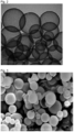
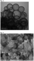
- TEM images Transmission electron microscopic images (TEM images) of the hollow silica particles obtained in Ex. 1 are shown in Figs. 1 and 2 .
- 116 primary particles having clear contours were selected from the TEM image shown in Fig. 1 , and their diameters were measured and calculated, whereupon the average was 278 nm. Further, the thickness of the shell in the TEM image shown in Fig. 2 measured was 15 nm.
- FIG. 3 A scanning electron microscopic image (SEM image) of the hollow silica particles obtained in Ex. 1 disintegrated by an agate mortar is shown in Fig. 3 . It is found from Fig. 3 that the hollow silica particles in Ex. 1 maintained the shape of the hollow particles even after disintegrated in the mortar.
- the mass concentration of Na in the shell of the hollow silica obtained in Ex. 1 was 3,800 mass ppm.
- n-dodecane was added, followed by stirring by a homogenizer manufactured by IKA until the entire liquid becomes uniform to prepare a crude emulsion.
- the crude emulsion was emulsified three times under a pressure of 400 bar by using a high pressure emulsifier (LAB1000 manufactured by SMT CO., LTD.) to prepare a fine emulsion.
- a high pressure emulsifier (LAB1000 manufactured by SMT CO., LTD.) to prepare a fine emulsion.
- the obtained precursor was baked at 550°C for 4 hours (temperature-raising rate: 10°C/min) to obtain 3 g of hollow silica particles.
- the BET specific surface area of the hollow silica obtained in Ex. 21 by nitrogen adsorption method was 554 m 2 /g.
- the shell layer is vague as compared with that in the TEM image shown in Fig. 2 , thus indicating a low denseness of the shell as compared with Ex. 1.
- FIG. 5 A SEM image of the hollow silica particles obtained in Ex. 21 disintegrated by an agate mortar is shown in Fig. 5 . It is found from Fig. 5 that most of the hollow silica particles in Ex. 21 collapsed since the silica shell strength was insufficient, and fragments of the silica shell were present in a large amount.
- the crude emulsion was emulsified three times under a pressure of 400 bar by using a high pressure emulsifier (LAB1000 manufactured by SMT CO., LTD.) to prepare a fine emulsion.
- a high pressure emulsifier (LAB1000 manufactured by SMT CO., LTD.) to prepare a fine emulsion.
- the suspension was maintained at 30°C for 2 days and slowly cooled to room temperature to obtain a hollow silica precursor dispersion.
- the cake collected by filtration was dried in a nitrogen atmosphere at 60°C for 1 hour and at 400°C for 4 hours (temperature-raising rate: 5°C/min) to obtain a hollow silica precursor.
- the obtained precursor was baked at 550°C for 4 hours (temperature-raising rate: 5°C/min) to obtain 13.8 g of hollow silica particles.
- the specific surface area of the hollow silica particles obtained in Ex. 2 is shown in Table 1.
- Silica particles were prepared in the same manner as in Ex. 2 except that the reaction temperature and the retention temperature in Second stage shell formation were changed.
- Silica particles were prepared in the same manner as in Ex. 5 except that the EO-PO-EO block copolymer was changed.
- EO-PO-EO block copolymers used in the respective Ex. are shown in Table 2.
- Silica particles were prepared in the same manner as in Ex. 5 except that the amount of the EO-PO-EO block copolymer (Kolliphor P188 manufactured by BASF) added was 10 times.
- the specific surface area of the hollow silica particles obtained in Ex. 14 was 140 m2 /g.
- Ultrasonic irradiation was conducted twice to the crude emulsion by an ultrasonic dispersing machine (GSCVP-600 manufactured by Sonic Technology Co., Ltd.) at an intensity of V-Level 3.4 for one minute to prepare a fine emulsion.
- GSCVP-600 manufactured by Sonic Technology Co., Ltd.
- the specific surface area of the hollow silica particles obtained in Ex. 15 was 170 m 2 /g.
- Ultrasonic irradiation was conducted twice to the crude emulsion by an ultrasonic dispersing machine (GSCVP-600 manufactured by Sonic Technology Co., Ltd.) at an intensity of V-Level 3.4 for one minute to prepare a fine emulsion.
- GSCVP-600 manufactured by Sonic Technology Co., Ltd.
- the cake collected by filtration was dried at 60°C for 2 days to remove AC-6000 thereby to obtain 8 g of hollow silica particles.
- the specific surface area of the hollow silica particles obtained in Ex. 16 was 80 m 2 /g.
- 13 g of an EO-PO-EO block copolymer (PE10500 manufactured by BASF) was added to 174 g of pure water and dissolved. The solution was maintained at 5°C, and 13 g of a PO-EO/PO block copolymer (25R-1 manufactured by ADEKA Corporation) was added and dissolved to obtain a transparent aqueous solution. 300 g of pure water was heated to 60°C, to which the block copolymer mixed solution was dropwise added with stirring, whereby a fine emulsion having a droplet size of about 300 nm was obtained.
- First stage shell formation and subsequent steps were conducted in the same manner as in Ex. 5 to prepare silica particles, except that First stage shell formation was conducted at 60°C, and the liquid having the silica material added was not maintained at pH 5, and a 1M sodium hydroxide aqueous solution was added to pH 9.
- the specific surface area of the hollow silica particles obtained in Ex. 17 was 160 m 2 /g.
Landscapes
- Chemical & Material Sciences (AREA)
- Organic Chemistry (AREA)
- Inorganic Chemistry (AREA)
- Engineering & Computer Science (AREA)
- Dispersion Chemistry (AREA)
- Chemical Kinetics & Catalysis (AREA)
- Nanotechnology (AREA)
- Physics & Mathematics (AREA)
- Condensed Matter Physics & Semiconductors (AREA)
- General Physics & Mathematics (AREA)
- Manufacturing & Machinery (AREA)
- Crystallography & Structural Chemistry (AREA)
- Silicon Compounds (AREA)
- Manufacturing Of Micro-Capsules (AREA)
- Agricultural Chemicals And Associated Chemicals (AREA)
Claims (11)
- Verfahren zur Herstellung hohler Siliziumdioxidteilchen, welches umfasst:Einstellen des pH-Wertes einer Öl-in-Wasser-Emulsion, die eine wässrige Phase, eine Ölphase und ein grenzflächenaktives Mittel enthält, auf höchstens 3,0 und Hinzufügen eines ersten Siliziumdioxidmaterials zu der Öl-in-Wasser-Emulsion,Hinzufügen eines zweiten Siliziumdioxidmaterials zu der Emulsion, der das erste Siliziumdioxidmaterial zugesetzt wurde, bei ihrem pH-Wert von mindestens 8 in Gegenwart von Alkalimetallionen, um eine Dispersion eines hohlen Siliziumdioxidvorläufers zu erhalten, undErhalten eines hohlen Siliziumdioxidvorläufers aus der Dispersion eines hohlen Siliziumdioxidvorläufers und Erhalten von hohlen Siliziumdioxidteilchen aus dem hohlen Siliziumdioxidvorläufer;wobei der hohle Siliziumdioxidvorläufer in Form von Ölkern/Siliziumdioxidhüllen-Teilchen vorliegt,der Anteil des Wassers in der wässrigen Phase von 90 bis 100 Massenprozent beträgt,das erste Siliziumdioxidmaterial und das zweite Siliziumdioxidmaterial jeweils unabhängig voneinander eine wässrige Lösung, in der wasserlösliches Siliziumdioxid gelöst ist, eine wässrige Dispersion, in der festes Siliziumdioxid dispergiert ist, ein Gemisch davon oder mindestens ein Mitglied, ausgewählt aus der Gruppe, besteht aus einem Alkalimetallsilikat und aktivierter Kieselsäure, oder einer wässrigen Lösung oder wässrigen Dispersion davon, sind, wobei die aktivierte Kieselsäure eine ist, die erhalten wird, durch Unterziehen eines Alkalimetallsilikats einem Kationenaustausch, um das Alkalimetall durch Wasserstoff auszutauschen,das Verfahren des Erhaltens des hohlen Siliziumdioxidvorläufers aus der Dispersion eines hohlen Siliziumdioxidvorläufers ausgewählt wird aus einem Verfahren des Unterziehens der Dispersion einer Filtration, einem Verfahren des Entfernens der wässrigen Phase durch Erwärmen oder einem Verfahren des Abtrennens des Vorläufers durch Sedimentation oder Zentrifugaltrennung, undein Verfahren des Entfernens des Ölkerns aus dem hohlen Siliziumdioxidvorläufer zum Erhalt von hohlen Siliziumdioxidteilchen ausgewählt wird aus einem Verfahren des Brennens des hohlen Siliziumdioxidvorläufers, so dass das Öl verbrannt und zersetzt wird, einem Verfahren des Verflüchtigens des Öls durch Trocknen, einem Verfahren des Hinzufügens eines geeigneten Additivs, um das Öl zu zersetzen, oder einem Verfahren des Extrahierens des Öls.
- Verfahren zur Herstellung hohler Siliziumdioxidteilchen nach Anspruch 1, wobei das erste Siliziumdioxidmaterial und das zweite Siliziumdioxidmaterial jeweils unabhängig voneinander mindestens ein Mitglied sind, ausgewählt aus der Gruppe, bestehend aus einem Alkalimetallsilikat und aktivierter Kieselsäure.
- Verfahren zur Herstellung hohler Siliziumdioxidteilchen nach Anspruch 2, wobei das Alkalimetallsilikat Natriumsilikat ist.
- Verfahren zur Herstellung hohler Siliziumdioxidteilchen nach einem der Ansprüche 1 bis 3, wobei als erstes Siliziumdioxidmaterial eine wässrige Alkalimetallsilikatlösung verwendet wird.
- Verfahren zur Herstellung hohler Siliziumdioxidteilchen nach einem der Ansprüche 1 bis 4, wobei als zweites Siliziumdioxidmaterial mindestens eines aus einer wässrigen Alkalimetallsilikatlösung oder einer wässrigen Lösung einer aktivierten Kieselsäure verwendet wird.
- Verfahren zur Herstellung hohler Siliziumdioxidteilchen nach einem der Ansprüche 1 bis 5, wobei das zweite Siliziumdioxidmaterial der erwärmten Emulsion zugesetzt wird.
- Verfahren zur Herstellung hohler Siliziumdioxidteilchen nach einem der Ansprüche 1 bis 6, wobei der Öl-in-Wasser-Emulsion eine Säure zugesetzt wird, um den pH-Wert auf mindestens 3 einzustellen, und dann als erstes Siliziumdioxidmaterial eine wässrige Alkalimetallsilikatlösung zugesetzt wird.
- Verfahren zur Herstellung hohler Siliziumdioxidteilchen nach einem der Ansprüche 1 bis 7, wobei der Emulsion nach dem Hinzufügen des ersten Siliziumdioxidmaterials eine Base zugesetzt wird und dann das zweite Siliziumdioxidmaterial hinzugefügt wird.
- Verfahren zur Herstellung hohler Siliziumdioxidteilchen nach einem der Ansprüche 1 bis 8, wobei der hohle Siliziumdioxidvorläufer gebrannt wird, um die hohlen Siliziumdioxidteilchen zu erhalten.
- Verfahren zur Herstellung hohler Siliziumdioxidteilchen nach Anspruch 9, wobei die Brenntemperatur 300 bis 800°C beträgt.
- Verfahren zur Herstellung hohler Siliziumdioxidteilchen nach einem der Ansprüche 1 bis 10, wobei das grenzflächenaktive Mittel ein Polyoxyethylen/Polyoxypropylen-Copolymer ist.
Priority Applications (1)
| Application Number | Priority Date | Filing Date | Title |
|---|---|---|---|
| EP23185872.1A EP4249434B1 (de) | 2017-12-26 | 2018-12-25 | Verfahren zur herstellung von hohlen kieselsäureteilchen |
Applications Claiming Priority (2)
| Application Number | Priority Date | Filing Date | Title |
|---|---|---|---|
| JP2017248972 | 2017-12-26 | ||
| PCT/JP2018/047619 WO2019131658A1 (ja) | 2017-12-26 | 2018-12-25 | 中空シリカ粒子の製造方法 |
Related Child Applications (1)
| Application Number | Title | Priority Date | Filing Date |
|---|---|---|---|
| EP23185872.1A Division EP4249434B1 (de) | 2017-12-26 | 2018-12-25 | Verfahren zur herstellung von hohlen kieselsäureteilchen |
Publications (3)
| Publication Number | Publication Date |
|---|---|
| EP3733603A1 EP3733603A1 (de) | 2020-11-04 |
| EP3733603A4 EP3733603A4 (de) | 2021-10-20 |
| EP3733603B1 true EP3733603B1 (de) | 2023-08-02 |
Family
ID=67063779
Family Applications (2)
| Application Number | Title | Priority Date | Filing Date |
|---|---|---|---|
| EP18895458.0A Active EP3733603B1 (de) | 2017-12-26 | 2018-12-25 | Verfahren zur herstellung von hohlen kieselsäureteilchen |
| EP23185872.1A Active EP4249434B1 (de) | 2017-12-26 | 2018-12-25 | Verfahren zur herstellung von hohlen kieselsäureteilchen |
Family Applications After (1)
| Application Number | Title | Priority Date | Filing Date |
|---|---|---|---|
| EP23185872.1A Active EP4249434B1 (de) | 2017-12-26 | 2018-12-25 | Verfahren zur herstellung von hohlen kieselsäureteilchen |
Country Status (5)
| Country | Link |
|---|---|
| US (2) | US11608273B2 (de) |
| EP (2) | EP3733603B1 (de) |
| JP (4) | JP7160839B2 (de) |
| CN (2) | CN111566047B (de) |
| WO (1) | WO2019131658A1 (de) |
Families Citing this family (17)
| Publication number | Priority date | Publication date | Assignee | Title |
|---|---|---|---|---|
| KR102131042B1 (ko) * | 2017-06-02 | 2020-07-08 | (주)아모레퍼시픽 | 다공성 무기 입자의 제조 방법 |
| EP3733603B1 (de) * | 2017-12-26 | 2023-08-02 | Agc Inc. | Verfahren zur herstellung von hohlen kieselsäureteilchen |
| JPWO2021020457A1 (de) * | 2019-07-31 | 2021-02-04 | ||
| JP2021046538A (ja) * | 2019-09-12 | 2021-03-25 | 三洋化成工業株式会社 | 樹脂組成物及び熱硬化物 |
| EP4112549A4 (de) * | 2020-02-27 | 2024-12-11 | Agc Inc. | Hohle kieselsäureteilchen und verfahren zu ihrer herstellung |
| JP7645053B2 (ja) * | 2020-07-17 | 2025-03-13 | 宇部エクシモ株式会社 | 中空無機粒子および該中空無機粒子の製造方法 |
| CN112592099A (zh) * | 2020-12-28 | 2021-04-02 | 成都翎渠杉建筑科技有限公司 | 一种高强度混凝土用添加剂的制备方法 |
| WO2023100676A1 (ja) * | 2021-11-30 | 2023-06-08 | Agc株式会社 | 中空シリカ粒子及びその製造方法 |
| KR102869130B1 (ko) | 2022-08-30 | 2025-10-14 | 가부시키가이샤 아도마텍쿠스 | 구상 실리카 입자, 슬러리 조성물, 수지 조성물 및 구상 실리카 입자의 제조 방법 |
| CN115367765B (zh) * | 2022-09-01 | 2023-07-25 | 安徽农业大学 | 一种小尺寸单孔空心二氧化硅球及其制备方法和应用 |
| JP2024047260A (ja) * | 2022-09-26 | 2024-04-05 | Agc株式会社 | マイクロカプセル粒子及びその製造方法 |
| CN115536031B (zh) * | 2022-10-24 | 2024-04-26 | 中国科学院过程工程研究所 | 一种二氧化硅微球及其制备方法 |
| WO2025028282A1 (ja) * | 2023-07-31 | 2025-02-06 | Agc株式会社 | 中空シリカ粒子の製造方法 |
| CN119701882B (zh) * | 2023-09-27 | 2026-01-06 | 中国石油化工股份有限公司 | 一种磁性多效能双亲杂化颗粒及其制备方法和应用 |
| CN119707050B (zh) * | 2023-09-27 | 2026-01-06 | 中国石油化工股份有限公司 | 一种磁性多效能双亲颗粒及其制备方法和应用 |
| CN117902582A (zh) * | 2023-12-29 | 2024-04-19 | 苏州西丽卡电子材料有限公司 | 一种中空话梅状二氧化硅微球及其制备方法 |
| WO2026042878A1 (ja) * | 2024-08-23 | 2026-02-26 | 花王株式会社 | シリカカプセル粒子の製造方法 |
Family Cites Families (17)
| Publication number | Priority date | Publication date | Assignee | Title |
|---|---|---|---|---|
| FR2747669B1 (fr) * | 1996-04-22 | 1998-05-22 | Rhone Poulenc Chimie | Procede de preparation de particules creuses de silice |
| JP5322042B2 (ja) | 2004-10-01 | 2013-10-23 | 独立行政法人産業技術総合研究所 | メソ細孔壁を有する中空シリカマイクロカプセル及びその製造方法 |
| JP4883383B2 (ja) * | 2005-06-02 | 2012-02-22 | 旭硝子株式会社 | 中空状SiO2を含有する分散液、塗料組成物及び反射防止塗膜付き基材 |
| WO2007060884A1 (ja) | 2005-11-25 | 2007-05-31 | Catalysts & Chemicals Industries Co., Ltd. | 中空シリカ微粒子、それを含む透明被膜形成用組成物、および透明被膜付基材 |
| JP5118328B2 (ja) * | 2006-10-31 | 2013-01-16 | 花王株式会社 | 中空シリカ粒子 |
| JP2010030791A (ja) * | 2008-07-25 | 2010-02-12 | Sony Corp | 中空シリカ粒子の製造方法 |
| JP5463099B2 (ja) * | 2009-08-21 | 2014-04-09 | 電気化学工業株式会社 | 中空シリカ粉末、その製造方法及び用途 |
| JP5603063B2 (ja) * | 2009-12-21 | 2014-10-08 | 花王株式会社 | 複合シリカ粒子の製造方法 |
| US9822010B2 (en) | 2010-01-21 | 2017-11-21 | CoLabs International Corporation | Ceramic encapsulation by use of one or more specialized silanes to template oil in an oil in water emulsion |
| CN101823719B (zh) * | 2010-05-18 | 2011-08-31 | 南京大学 | 二氧化硅中空粒子的两步法制备方法 |
| CN102249245B (zh) * | 2011-04-28 | 2012-12-26 | 华南理工大学 | 一种单孔二氧化硅中空微球的制备方法 |
| WO2013121703A1 (ja) * | 2012-02-13 | 2013-08-22 | 株式会社トクヤマシルテック | 新規な特性プロファイルを有するシリカバルーン材料 |
| JP6207345B2 (ja) * | 2013-10-30 | 2017-10-04 | 日揮触媒化成株式会社 | シリカ粒子の製造方法 |
| WO2015083836A1 (ja) * | 2013-12-06 | 2015-06-11 | 花王株式会社 | マイクロカプセルの製造方法 |
| WO2016137456A1 (en) * | 2015-02-25 | 2016-09-01 | The Chemours Company Tt, Llc | Process for preparing high % solids inorganic hollow particle dispersions using an interfacial miniemulsion sol-gel reaction |
| JP6552387B2 (ja) * | 2015-11-06 | 2019-07-31 | 花王株式会社 | 中空シリカ粒子の製造方法 |
| EP3733603B1 (de) * | 2017-12-26 | 2023-08-02 | Agc Inc. | Verfahren zur herstellung von hohlen kieselsäureteilchen |
-
2018
- 2018-12-25 EP EP18895458.0A patent/EP3733603B1/de active Active
- 2018-12-25 CN CN201880083744.0A patent/CN111566047B/zh active Active
- 2018-12-25 CN CN202310895158.9A patent/CN116924418B/zh active Active
- 2018-12-25 JP JP2019562038A patent/JP7160839B2/ja active Active
- 2018-12-25 EP EP23185872.1A patent/EP4249434B1/de active Active
- 2018-12-25 WO PCT/JP2018/047619 patent/WO2019131658A1/ja not_active Ceased
-
2019
- 2019-06-26 JP JP2019118930A patent/JP2022034094A/ja active Pending
-
2020
- 2020-05-28 US US16/885,487 patent/US11608273B2/en active Active
-
2022
- 2022-10-12 JP JP2022164127A patent/JP7401627B2/ja active Active
- 2022-12-29 US US18/090,557 patent/US12157673B2/en active Active
-
2023
- 2023-12-06 JP JP2023206052A patent/JP7723063B2/ja active Active
Also Published As
| Publication number | Publication date |
|---|---|
| JP7401627B2 (ja) | 2023-12-19 |
| EP4249434A2 (de) | 2023-09-27 |
| US20230138940A1 (en) | 2023-05-04 |
| US12157673B2 (en) | 2024-12-03 |
| EP3733603A4 (de) | 2021-10-20 |
| JPWO2019131658A1 (ja) | 2020-12-17 |
| US11608273B2 (en) | 2023-03-21 |
| CN116924418A (zh) | 2023-10-24 |
| WO2019131658A1 (ja) | 2019-07-04 |
| CN111566047B (zh) | 2023-07-25 |
| JP7723063B2 (ja) | 2025-08-13 |
| EP4249434A3 (de) | 2024-03-13 |
| EP4249434B1 (de) | 2025-06-04 |
| JP2022179707A (ja) | 2022-12-02 |
| JP2022034094A (ja) | 2022-03-03 |
| EP3733603A1 (de) | 2020-11-04 |
| JP2024019309A (ja) | 2024-02-08 |
| CN111566047A (zh) | 2020-08-21 |
| JP7160839B2 (ja) | 2022-10-25 |
| CN116924418B (zh) | 2026-02-27 |
| US20200283300A1 (en) | 2020-09-10 |
Similar Documents
| Publication | Publication Date | Title |
|---|---|---|
| EP3733603B1 (de) | Verfahren zur herstellung von hohlen kieselsäureteilchen | |
| CN115210179B (zh) | 中空二氧化硅颗粒及中空二氧化硅颗粒的制造方法 | |
| TW201738178A (zh) | 中空二氧化矽粒子及其製造方法 | |
| WO2012110995A1 (en) | Silica core-shell microparticles | |
| TW202233158A (zh) | 多孔質球狀氧化矽及其製造方法 | |
| WO2020138106A1 (ja) | 球状中空シリカ粒子群、内包剤、分散液及び水分散液 | |
| JP4737922B2 (ja) | 微粒子状メソポーラスシリカの製造方法 | |
| JP2021100892A (ja) | 中空粒子の製造方法 | |
| JP2019094234A (ja) | シリカエアロゲルの製造方法 | |
| EP4292983A1 (de) | Verfahren zur herstellung von porösen kern-schale-kieselsäureteilchen und poröse kern-schale-kieselsäureteilchen | |
| KR102961336B1 (ko) | 중공 실리카 입자 및 중공 실리카 입자의 제조 방법 | |
| KR102961337B1 (ko) | 중공 실리카 입자 및 그 제조 방법 | |
| WO2025028282A1 (ja) | 中空シリカ粒子の製造方法 | |
| TW202525713A (zh) | 多孔質球狀二氧化矽及其製造方法 |
Legal Events
| Date | Code | Title | Description |
|---|---|---|---|
| STAA | Information on the status of an ep patent application or granted ep patent |
Free format text: STATUS: THE INTERNATIONAL PUBLICATION HAS BEEN MADE |
|
| PUAI | Public reference made under article 153(3) epc to a published international application that has entered the european phase |
Free format text: ORIGINAL CODE: 0009012 |
|
| STAA | Information on the status of an ep patent application or granted ep patent |
Free format text: STATUS: REQUEST FOR EXAMINATION WAS MADE |
|
| 17P | Request for examination filed |
Effective date: 20200702 |
|
| AK | Designated contracting states |
Kind code of ref document: A1 Designated state(s): AL AT BE BG CH CY CZ DE DK EE ES FI FR GB GR HR HU IE IS IT LI LT LU LV MC MK MT NL NO PL PT RO RS SE SI SK SM TR |
|
| AX | Request for extension of the european patent |
Extension state: BA ME |
|
| DAV | Request for validation of the european patent (deleted) | ||
| DAX | Request for extension of the european patent (deleted) | ||
| A4 | Supplementary search report drawn up and despatched |
Effective date: 20210921 |
|
| RIC1 | Information provided on ipc code assigned before grant |
Ipc: C01B 33/193 20060101ALI20210914BHEP Ipc: B01J 13/14 20060101ALI20210914BHEP Ipc: C01B 33/187 20060101ALI20210914BHEP Ipc: C01B 33/18 20060101AFI20210914BHEP |
|
| STAA | Information on the status of an ep patent application or granted ep patent |
Free format text: STATUS: EXAMINATION IS IN PROGRESS |
|
| 17Q | First examination report despatched |
Effective date: 20220419 |
|
| GRAP | Despatch of communication of intention to grant a patent |
Free format text: ORIGINAL CODE: EPIDOSNIGR1 |
|
| STAA | Information on the status of an ep patent application or granted ep patent |
Free format text: STATUS: GRANT OF PATENT IS INTENDED |
|
| INTG | Intention to grant announced |
Effective date: 20230331 |
|
| P01 | Opt-out of the competence of the unified patent court (upc) registered |
Effective date: 20230501 |
|
| GRAS | Grant fee paid |
Free format text: ORIGINAL CODE: EPIDOSNIGR3 |
|
| GRAA | (expected) grant |
Free format text: ORIGINAL CODE: 0009210 |
|
| STAA | Information on the status of an ep patent application or granted ep patent |
Free format text: STATUS: THE PATENT HAS BEEN GRANTED |
|
| AK | Designated contracting states |
Kind code of ref document: B1 Designated state(s): AL AT BE BG CH CY CZ DE DK EE ES FI FR GB GR HR HU IE IS IT LI LT LU LV MC MK MT NL NO PL PT RO RS SE SI SK SM TR |
|
| REG | Reference to a national code |
Ref country code: GB Ref legal event code: FG4D |
|
| REG | Reference to a national code |
Ref country code: CH Ref legal event code: EP |
|
| REG | Reference to a national code |
Ref country code: DE Ref legal event code: R096 Ref document number: 602018054794 Country of ref document: DE |
|
| REG | Reference to a national code |
Ref country code: IE Ref legal event code: FG4D |
|
| REG | Reference to a national code |
Ref country code: LT Ref legal event code: MG9D |
|
| REG | Reference to a national code |
Ref country code: NL Ref legal event code: MP Effective date: 20230802 |
|
| REG | Reference to a national code |
Ref country code: AT Ref legal event code: MK05 Ref document number: 1594564 Country of ref document: AT Kind code of ref document: T Effective date: 20230802 |
|
| PG25 | Lapsed in a contracting state [announced via postgrant information from national office to epo] |
Ref country code: GR Free format text: LAPSE BECAUSE OF FAILURE TO SUBMIT A TRANSLATION OF THE DESCRIPTION OR TO PAY THE FEE WITHIN THE PRESCRIBED TIME-LIMIT Effective date: 20231103 |
|
| PG25 | Lapsed in a contracting state [announced via postgrant information from national office to epo] |
Ref country code: IS Free format text: LAPSE BECAUSE OF FAILURE TO SUBMIT A TRANSLATION OF THE DESCRIPTION OR TO PAY THE FEE WITHIN THE PRESCRIBED TIME-LIMIT Effective date: 20231202 |
|
| PG25 | Lapsed in a contracting state [announced via postgrant information from national office to epo] |
Ref country code: SE Free format text: LAPSE BECAUSE OF FAILURE TO SUBMIT A TRANSLATION OF THE DESCRIPTION OR TO PAY THE FEE WITHIN THE PRESCRIBED TIME-LIMIT Effective date: 20230802 Ref country code: RS Free format text: LAPSE BECAUSE OF FAILURE TO SUBMIT A TRANSLATION OF THE DESCRIPTION OR TO PAY THE FEE WITHIN THE PRESCRIBED TIME-LIMIT Effective date: 20230802 Ref country code: PT Free format text: LAPSE BECAUSE OF FAILURE TO SUBMIT A TRANSLATION OF THE DESCRIPTION OR TO PAY THE FEE WITHIN THE PRESCRIBED TIME-LIMIT Effective date: 20231204 Ref country code: NO Free format text: LAPSE BECAUSE OF FAILURE TO SUBMIT A TRANSLATION OF THE DESCRIPTION OR TO PAY THE FEE WITHIN THE PRESCRIBED TIME-LIMIT Effective date: 20231102 Ref country code: NL Free format text: LAPSE BECAUSE OF FAILURE TO SUBMIT A TRANSLATION OF THE DESCRIPTION OR TO PAY THE FEE WITHIN THE PRESCRIBED TIME-LIMIT Effective date: 20230802 Ref country code: LV Free format text: LAPSE BECAUSE OF FAILURE TO SUBMIT A TRANSLATION OF THE DESCRIPTION OR TO PAY THE FEE WITHIN THE PRESCRIBED TIME-LIMIT Effective date: 20230802 Ref country code: LT Free format text: LAPSE BECAUSE OF FAILURE TO SUBMIT A TRANSLATION OF THE DESCRIPTION OR TO PAY THE FEE WITHIN THE PRESCRIBED TIME-LIMIT Effective date: 20230802 Ref country code: IS Free format text: LAPSE BECAUSE OF FAILURE TO SUBMIT A TRANSLATION OF THE DESCRIPTION OR TO PAY THE FEE WITHIN THE PRESCRIBED TIME-LIMIT Effective date: 20231202 Ref country code: HR Free format text: LAPSE BECAUSE OF FAILURE TO SUBMIT A TRANSLATION OF THE DESCRIPTION OR TO PAY THE FEE WITHIN THE PRESCRIBED TIME-LIMIT Effective date: 20230802 Ref country code: GR Free format text: LAPSE BECAUSE OF FAILURE TO SUBMIT A TRANSLATION OF THE DESCRIPTION OR TO PAY THE FEE WITHIN THE PRESCRIBED TIME-LIMIT Effective date: 20231103 Ref country code: FI Free format text: LAPSE BECAUSE OF FAILURE TO SUBMIT A TRANSLATION OF THE DESCRIPTION OR TO PAY THE FEE WITHIN THE PRESCRIBED TIME-LIMIT Effective date: 20230802 Ref country code: AT Free format text: LAPSE BECAUSE OF FAILURE TO SUBMIT A TRANSLATION OF THE DESCRIPTION OR TO PAY THE FEE WITHIN THE PRESCRIBED TIME-LIMIT Effective date: 20230802 |
|
| PG25 | Lapsed in a contracting state [announced via postgrant information from national office to epo] |
Ref country code: PL Free format text: LAPSE BECAUSE OF FAILURE TO SUBMIT A TRANSLATION OF THE DESCRIPTION OR TO PAY THE FEE WITHIN THE PRESCRIBED TIME-LIMIT Effective date: 20230802 |
|
| PG25 | Lapsed in a contracting state [announced via postgrant information from national office to epo] |
Ref country code: ES Free format text: LAPSE BECAUSE OF FAILURE TO SUBMIT A TRANSLATION OF THE DESCRIPTION OR TO PAY THE FEE WITHIN THE PRESCRIBED TIME-LIMIT Effective date: 20230802 |
|
| PG25 | Lapsed in a contracting state [announced via postgrant information from national office to epo] |
Ref country code: SM Free format text: LAPSE BECAUSE OF FAILURE TO SUBMIT A TRANSLATION OF THE DESCRIPTION OR TO PAY THE FEE WITHIN THE PRESCRIBED TIME-LIMIT Effective date: 20230802 Ref country code: RO Free format text: LAPSE BECAUSE OF FAILURE TO SUBMIT A TRANSLATION OF THE DESCRIPTION OR TO PAY THE FEE WITHIN THE PRESCRIBED TIME-LIMIT Effective date: 20230802 Ref country code: ES Free format text: LAPSE BECAUSE OF FAILURE TO SUBMIT A TRANSLATION OF THE DESCRIPTION OR TO PAY THE FEE WITHIN THE PRESCRIBED TIME-LIMIT Effective date: 20230802 Ref country code: EE Free format text: LAPSE BECAUSE OF FAILURE TO SUBMIT A TRANSLATION OF THE DESCRIPTION OR TO PAY THE FEE WITHIN THE PRESCRIBED TIME-LIMIT Effective date: 20230802 Ref country code: DK Free format text: LAPSE BECAUSE OF FAILURE TO SUBMIT A TRANSLATION OF THE DESCRIPTION OR TO PAY THE FEE WITHIN THE PRESCRIBED TIME-LIMIT Effective date: 20230802 Ref country code: CZ Free format text: LAPSE BECAUSE OF FAILURE TO SUBMIT A TRANSLATION OF THE DESCRIPTION OR TO PAY THE FEE WITHIN THE PRESCRIBED TIME-LIMIT Effective date: 20230802 Ref country code: SK Free format text: LAPSE BECAUSE OF FAILURE TO SUBMIT A TRANSLATION OF THE DESCRIPTION OR TO PAY THE FEE WITHIN THE PRESCRIBED TIME-LIMIT Effective date: 20230802 |
|
| REG | Reference to a national code |
Ref country code: DE Ref legal event code: R097 Ref document number: 602018054794 Country of ref document: DE |
|
| PG25 | Lapsed in a contracting state [announced via postgrant information from national office to epo] |
Ref country code: IT Free format text: LAPSE BECAUSE OF FAILURE TO SUBMIT A TRANSLATION OF THE DESCRIPTION OR TO PAY THE FEE WITHIN THE PRESCRIBED TIME-LIMIT Effective date: 20230802 |
|
| PLBE | No opposition filed within time limit |
Free format text: ORIGINAL CODE: 0009261 |
|
| STAA | Information on the status of an ep patent application or granted ep patent |
Free format text: STATUS: NO OPPOSITION FILED WITHIN TIME LIMIT |
|
| 26N | No opposition filed |
Effective date: 20240503 |
|
| PG25 | Lapsed in a contracting state [announced via postgrant information from national office to epo] |
Ref country code: SI Free format text: LAPSE BECAUSE OF FAILURE TO SUBMIT A TRANSLATION OF THE DESCRIPTION OR TO PAY THE FEE WITHIN THE PRESCRIBED TIME-LIMIT Effective date: 20230802 |
|
| REG | Reference to a national code |
Ref country code: CH Ref legal event code: PL |
|
| PG25 | Lapsed in a contracting state [announced via postgrant information from national office to epo] |
Ref country code: LU Free format text: LAPSE BECAUSE OF NON-PAYMENT OF DUE FEES Effective date: 20231225 |
|
| PG25 | Lapsed in a contracting state [announced via postgrant information from national office to epo] |
Ref country code: MC Free format text: LAPSE BECAUSE OF FAILURE TO SUBMIT A TRANSLATION OF THE DESCRIPTION OR TO PAY THE FEE WITHIN THE PRESCRIBED TIME-LIMIT Effective date: 20230802 |
|
| REG | Reference to a national code |
Ref country code: BE Ref legal event code: MM Effective date: 20231231 |
|
| PG25 | Lapsed in a contracting state [announced via postgrant information from national office to epo] |
Ref country code: MC Free format text: LAPSE BECAUSE OF FAILURE TO SUBMIT A TRANSLATION OF THE DESCRIPTION OR TO PAY THE FEE WITHIN THE PRESCRIBED TIME-LIMIT Effective date: 20230802 Ref country code: LU Free format text: LAPSE BECAUSE OF NON-PAYMENT OF DUE FEES Effective date: 20231225 |
|
| REG | Reference to a national code |
Ref country code: IE Ref legal event code: MM4A |
|
| PG25 | Lapsed in a contracting state [announced via postgrant information from national office to epo] |
Ref country code: IE Free format text: LAPSE BECAUSE OF NON-PAYMENT OF DUE FEES Effective date: 20231225 |
|
| PG25 | Lapsed in a contracting state [announced via postgrant information from national office to epo] |
Ref country code: BE Free format text: LAPSE BECAUSE OF NON-PAYMENT OF DUE FEES Effective date: 20231231 |
|
| PG25 | Lapsed in a contracting state [announced via postgrant information from national office to epo] |
Ref country code: CH Free format text: LAPSE BECAUSE OF NON-PAYMENT OF DUE FEES Effective date: 20231231 |
|
| PG25 | Lapsed in a contracting state [announced via postgrant information from national office to epo] |
Ref country code: IE Free format text: LAPSE BECAUSE OF NON-PAYMENT OF DUE FEES Effective date: 20231225 Ref country code: CH Free format text: LAPSE BECAUSE OF NON-PAYMENT OF DUE FEES Effective date: 20231231 Ref country code: BE Free format text: LAPSE BECAUSE OF NON-PAYMENT OF DUE FEES Effective date: 20231231 |
|
| PG25 | Lapsed in a contracting state [announced via postgrant information from national office to epo] |
Ref country code: BG Free format text: LAPSE BECAUSE OF FAILURE TO SUBMIT A TRANSLATION OF THE DESCRIPTION OR TO PAY THE FEE WITHIN THE PRESCRIBED TIME-LIMIT Effective date: 20230802 |
|
| PG25 | Lapsed in a contracting state [announced via postgrant information from national office to epo] |
Ref country code: BG Free format text: LAPSE BECAUSE OF FAILURE TO SUBMIT A TRANSLATION OF THE DESCRIPTION OR TO PAY THE FEE WITHIN THE PRESCRIBED TIME-LIMIT Effective date: 20230802 |
|
| PG25 | Lapsed in a contracting state [announced via postgrant information from national office to epo] |
Ref country code: CY Free format text: LAPSE BECAUSE OF FAILURE TO SUBMIT A TRANSLATION OF THE DESCRIPTION OR TO PAY THE FEE WITHIN THE PRESCRIBED TIME-LIMIT; INVALID AB INITIO Effective date: 20181225 |
|
| PG25 | Lapsed in a contracting state [announced via postgrant information from national office to epo] |
Ref country code: HU Free format text: LAPSE BECAUSE OF FAILURE TO SUBMIT A TRANSLATION OF THE DESCRIPTION OR TO PAY THE FEE WITHIN THE PRESCRIBED TIME-LIMIT; INVALID AB INITIO Effective date: 20181225 |
|
| PG25 | Lapsed in a contracting state [announced via postgrant information from national office to epo] |
Ref country code: TR Free format text: LAPSE BECAUSE OF FAILURE TO SUBMIT A TRANSLATION OF THE DESCRIPTION OR TO PAY THE FEE WITHIN THE PRESCRIBED TIME-LIMIT Effective date: 20230802 |
|
| PGFP | Annual fee paid to national office [announced via postgrant information from national office to epo] |
Ref country code: DE Payment date: 20251211 Year of fee payment: 8 |
|
| PGFP | Annual fee paid to national office [announced via postgrant information from national office to epo] |
Ref country code: GB Payment date: 20251219 Year of fee payment: 8 |
|
| PGFP | Annual fee paid to national office [announced via postgrant information from national office to epo] |
Ref country code: FR Payment date: 20251229 Year of fee payment: 8 |