EP3734112B1 - Planetengetriebe - Google Patents
Planetengetriebe Download PDFInfo
- Publication number
- EP3734112B1 EP3734112B1 EP19171876.6A EP19171876A EP3734112B1 EP 3734112 B1 EP3734112 B1 EP 3734112B1 EP 19171876 A EP19171876 A EP 19171876A EP 3734112 B1 EP3734112 B1 EP 3734112B1
- Authority
- EP
- European Patent Office
- Prior art keywords
- transmission
- planet carrier
- planetary
- sun shaft
- torque
- Prior art date
- Legal status (The legal status is an assumption and is not a legal conclusion. Google has not performed a legal analysis and makes no representation as to the accuracy of the status listed.)
- Active
Links
Images



Classifications
-
- F—MECHANICAL ENGINEERING; LIGHTING; HEATING; WEAPONS; BLASTING
- F03—MACHINES OR ENGINES FOR LIQUIDS; WIND, SPRING, OR WEIGHT MOTORS; PRODUCING MECHANICAL POWER OR A REACTIVE PROPULSIVE THRUST, NOT OTHERWISE PROVIDED FOR
- F03D—WIND MOTORS
- F03D15/00—Transmission of mechanical power
-
- F—MECHANICAL ENGINEERING; LIGHTING; HEATING; WEAPONS; BLASTING
- F03—MACHINES OR ENGINES FOR LIQUIDS; WIND, SPRING, OR WEIGHT MOTORS; PRODUCING MECHANICAL POWER OR A REACTIVE PROPULSIVE THRUST, NOT OTHERWISE PROVIDED FOR
- F03D—WIND MOTORS
- F03D80/00—Details, components or accessories not provided for in groups F03D1/00 - F03D17/00
-
- F—MECHANICAL ENGINEERING; LIGHTING; HEATING; WEAPONS; BLASTING
- F16—ENGINEERING ELEMENTS AND UNITS; GENERAL MEASURES FOR PRODUCING AND MAINTAINING EFFECTIVE FUNCTIONING OF MACHINES OR INSTALLATIONS; THERMAL INSULATION IN GENERAL
- F16D—COUPLINGS FOR TRANSMITTING ROTATION; CLUTCHES; BRAKES
- F16D1/00—Couplings for rigidly connecting two coaxial shafts or other movable machine elements
- F16D1/06—Couplings for rigidly connecting two coaxial shafts or other movable machine elements for attachment of a member on a shaft or on a shaft-end
-
- F—MECHANICAL ENGINEERING; LIGHTING; HEATING; WEAPONS; BLASTING
- F16—ENGINEERING ELEMENTS AND UNITS; GENERAL MEASURES FOR PRODUCING AND MAINTAINING EFFECTIVE FUNCTIONING OF MACHINES OR INSTALLATIONS; THERMAL INSULATION IN GENERAL
- F16D—COUPLINGS FOR TRANSMITTING ROTATION; CLUTCHES; BRAKES
- F16D1/00—Couplings for rigidly connecting two coaxial shafts or other movable machine elements
- F16D1/06—Couplings for rigidly connecting two coaxial shafts or other movable machine elements for attachment of a member on a shaft or on a shaft-end
- F16D1/076—Couplings for rigidly connecting two coaxial shafts or other movable machine elements for attachment of a member on a shaft or on a shaft-end by clamping together two faces perpendicular to the axis of rotation, e.g. with bolted flanges
-
- F—MECHANICAL ENGINEERING; LIGHTING; HEATING; WEAPONS; BLASTING
- F16—ENGINEERING ELEMENTS AND UNITS; GENERAL MEASURES FOR PRODUCING AND MAINTAINING EFFECTIVE FUNCTIONING OF MACHINES OR INSTALLATIONS; THERMAL INSULATION IN GENERAL
- F16H—GEARING
- F16H1/00—Toothed gearings for conveying rotary motion
- F16H1/28—Toothed gearings for conveying rotary motion with gears having orbital motion
- F16H1/32—Toothed gearings for conveying rotary motion with gears having orbital motion in which the central axis of the gearing lies inside the periphery of an orbital gear
-
- F—MECHANICAL ENGINEERING; LIGHTING; HEATING; WEAPONS; BLASTING
- F16—ENGINEERING ELEMENTS AND UNITS; GENERAL MEASURES FOR PRODUCING AND MAINTAINING EFFECTIVE FUNCTIONING OF MACHINES OR INSTALLATIONS; THERMAL INSULATION IN GENERAL
- F16H—GEARING
- F16H1/00—Toothed gearings for conveying rotary motion
- F16H1/28—Toothed gearings for conveying rotary motion with gears having orbital motion
- F16H1/46—Systems consisting of a plurality of gear trains each with orbital gears, i.e. systems having three or more central gears
-
- F—MECHANICAL ENGINEERING; LIGHTING; HEATING; WEAPONS; BLASTING
- F16—ENGINEERING ELEMENTS AND UNITS; GENERAL MEASURES FOR PRODUCING AND MAINTAINING EFFECTIVE FUNCTIONING OF MACHINES OR INSTALLATIONS; THERMAL INSULATION IN GENERAL
- F16H—GEARING
- F16H57/00—General details of gearing
- F16H57/02—Gearboxes; Mounting gearing therein
- F16H57/023—Mounting or installation of gears or shafts in the gearboxes, e.g. methods or means for assembly
-
- F—MECHANICAL ENGINEERING; LIGHTING; HEATING; WEAPONS; BLASTING
- F16—ENGINEERING ELEMENTS AND UNITS; GENERAL MEASURES FOR PRODUCING AND MAINTAINING EFFECTIVE FUNCTIONING OF MACHINES OR INSTALLATIONS; THERMAL INSULATION IN GENERAL
- F16H—GEARING
- F16H57/00—General details of gearing
- F16H57/08—General details of gearing of gearings with members having orbital motion
- F16H57/082—Planet carriers
-
- F—MECHANICAL ENGINEERING; LIGHTING; HEATING; WEAPONS; BLASTING
- F16—ENGINEERING ELEMENTS AND UNITS; GENERAL MEASURES FOR PRODUCING AND MAINTAINING EFFECTIVE FUNCTIONING OF MACHINES OR INSTALLATIONS; THERMAL INSULATION IN GENERAL
- F16D—COUPLINGS FOR TRANSMITTING ROTATION; CLUTCHES; BRAKES
- F16D1/00—Couplings for rigidly connecting two coaxial shafts or other movable machine elements
- F16D1/10—Quick-acting couplings in which the parts are connected by simply bringing them together axially
- F16D1/101—Quick-acting couplings in which the parts are connected by simply bringing them together axially without axial retaining means rotating with the coupling
-
- F—MECHANICAL ENGINEERING; LIGHTING; HEATING; WEAPONS; BLASTING
- F16—ENGINEERING ELEMENTS AND UNITS; GENERAL MEASURES FOR PRODUCING AND MAINTAINING EFFECTIVE FUNCTIONING OF MACHINES OR INSTALLATIONS; THERMAL INSULATION IN GENERAL
- F16D—COUPLINGS FOR TRANSMITTING ROTATION; CLUTCHES; BRAKES
- F16D1/00—Couplings for rigidly connecting two coaxial shafts or other movable machine elements
- F16D1/10—Quick-acting couplings in which the parts are connected by simply bringing them together axially
- F16D2001/103—Quick-acting couplings in which the parts are connected by simply bringing them together axially the torque is transmitted via splined connections
-
- F—MECHANICAL ENGINEERING; LIGHTING; HEATING; WEAPONS; BLASTING
- F16—ENGINEERING ELEMENTS AND UNITS; GENERAL MEASURES FOR PRODUCING AND MAINTAINING EFFECTIVE FUNCTIONING OF MACHINES OR INSTALLATIONS; THERMAL INSULATION IN GENERAL
- F16H—GEARING
- F16H57/00—General details of gearing
- F16H57/02—Gearboxes; Mounting gearing therein
- F16H2057/02039—Gearboxes for particular applications
- F16H2057/02078—Gearboxes for particular applications for wind turbines
-
- F—MECHANICAL ENGINEERING; LIGHTING; HEATING; WEAPONS; BLASTING
- F16—ENGINEERING ELEMENTS AND UNITS; GENERAL MEASURES FOR PRODUCING AND MAINTAINING EFFECTIVE FUNCTIONING OF MACHINES OR INSTALLATIONS; THERMAL INSULATION IN GENERAL
- F16H—GEARING
- F16H57/00—General details of gearing
- F16H57/02—Gearboxes; Mounting gearing therein
- F16H2057/02086—Measures for reducing size of gearbox, e.g. for creating a more compact transmission casing
-
- Y—GENERAL TAGGING OF NEW TECHNOLOGICAL DEVELOPMENTS; GENERAL TAGGING OF CROSS-SECTIONAL TECHNOLOGIES SPANNING OVER SEVERAL SECTIONS OF THE IPC; TECHNICAL SUBJECTS COVERED BY FORMER USPC CROSS-REFERENCE ART COLLECTIONS [XRACs] AND DIGESTS
- Y02—TECHNOLOGIES OR APPLICATIONS FOR MITIGATION OR ADAPTATION AGAINST CLIMATE CHANGE
- Y02E—REDUCTION OF GREENHOUSE GAS [GHG] EMISSIONS, RELATED TO ENERGY GENERATION, TRANSMISSION OR DISTRIBUTION
- Y02E10/00—Energy generation through renewable energy sources
- Y02E10/70—Wind energy
- Y02E10/72—Wind turbines with rotation axis in wind direction
Definitions
- the invention relates to a planetary gear with at least two gear stages, wherein a sun shaft of a planetary stage is connected to a planet carrier of a further planetary stage following this planetary stage via a coupling toothing for torque transmission.
- the invention further relates to a drive train in which a corresponding planetary gear is used as a gear, a wind turbine equipped with such a drive train, and an industrial application that has such a planetary gear as a gear.
- the German utility model DE 92 02 238 shows a shaft split by means of a Hirth gearing, which is connected on the output side to a planet carrier of a planetary gear.
- the present invention creates a planetary gear of the type mentioned at the beginning, which is characterized in that the coupling toothing is a planar spline toothing. Thanks to the use of such a planar spline toothing according to the invention, which is often also referred to as spur toothing, it is possible to save installation space axially and/or radially with respect to a main axis of rotation, which significantly facilitates the design of the planetary gear based on an overall dimension specified by the customer.
- the face gears forming the planar spline gearing are provided on the one hand on a face of the sun shaft and on the other hand on a face of the planet carrier that is axially adjacent to this face of the sun shaft with respect to the main axis of rotation.
- the sun shaft and the planet carrier are connected at the face directly via the Plane spline gearing is connected to one another, which makes the provision of a hub superfluous at this point.
- this allows for space savings in relation to the main axis of rotation in the axial and radial directions.
- the planet carrier is very inexpensive to manufacture, as little material is required for it. In addition, it is very easily accessible for machining.
- the sun shaft and the planet carrier are fastened to one another using fastening elements that extend axially with respect to the main axis of rotation and are preferably positioned at regular intervals from one another.
- the fastening elements are advantageously fastening screws that are positioned on a common bolt circle. Fastening screws of this type provide a particularly simple and inexpensive axial securing of the connection between the sun shaft and the planet carrier.
- the fastening elements extend through the planar spline toothing. In this way, radial installation space can be saved, particularly with respect to the main axis of rotation, if the sun shaft is designed as a hollow shaft.
- the spur gears forming the planar spline toothing are provided on the one hand on a front side of a hub that is attached in a rotationally fixed manner to the outer circumference of the sun shaft and on the other hand on a front side of the planet carrier that is axially adjacent to this front side of the sun shaft.
- the sun shaft and the planet carrier are thus indirectly connected to one another via a hub arranged on the outer circumference of the sun shaft, with the planar spline toothing being provided on the hub and on the planet carrier.
- the machining of the hub and the planet carrier can be commissioned separately and operators can be selected who are optimally equipped for the respective machining. Logistics costs can also be saved, as the entire planet carrier often has to be transported over long distances to machine the hub section.
- the hub and the planet carrier are preferably attached to one another using fastening elements that extend axially in relation to the main axis of rotation and are positioned at regular intervals from one another.
- the fastening elements are advantageously fastening screws that are positioned on a common bolt circle.
- the fastening elements also extend through the planar splines.
- the hub is connected to the sun shaft via a coupling toothing and is secured in particular against axial displacement with respect to the main axis of rotation, resulting in a simple and stable construction.
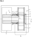
- FIG 1 shows components of a planetary gear 1 according to an embodiment of the present invention, more precisely a sun shaft 2 of a planetary stage 17, which is designed as a single piece as a hollow shaft, and a planet carrier 3 of a further planetary stage 18 following this planetary stage 17, which is connected to it and is also designed as a single piece in this case.
- the sun shaft 2 is provided with a sun gear 4 at its first free end.
- a spur gear 10 is formed on the front side with teeth that extend at least substantially radially with respect to a main axis of rotation 19 of the planetary gear 1, which defines a first part of a planar spline gear.
- a plurality of threaded holes 11 are arranged on the front side of the second free end of the sun shaft 2, which extend through the spur gear 10 in the axial direction with respect to the main axis of rotation 19 and are positioned at equal intervals along a bolt circle.
- the planet carrier 3 defines at its first free end facing the sun shaft 2 a spur gear 12 with teeth that extend at least substantially radially with respect to the main axis of rotation 19, which is designed in accordance with the spur gear 10 of the sun shaft 2 and defines the second part of the planar spline gear.
- the spur gear 12 of the planet carrier 3 can be axially aligned with respect to the main axis of rotation 19 in such a way as to Sun shaft 2 can be placed so that the sun shaft 2 and the planet carrier 3 are centered relative to one another, connected to one another in a rotationally fixed manner and secured in the radial direction and in the circumferential direction with respect to the main axis of rotation 19.
- through holes 13 corresponding to the threaded holes 11 of the sun shaft 2 are formed, through which fastening elements 14, in this case in the form of fastening screws, are inserted from the outside and screwed into the threaded holes 11.
- the spur gearing 12 and the through holes 13 are provided on an annular flange 15 which projects radially inwards with respect to the main axis of rotation 19 and which is dimensioned such that the fastening elements 14 can be inserted into the through holes 13 starting from the free end of the planet carrier 3 facing away from the sun shaft 2.
- the planet carrier 3 has a planet gear receiving section 7 and an end section 8.
- the FIG 1 The structure shown is characterized in particular by the fact that, thanks to the fact that the torque is transmitted by a planar spline connecting the sun shaft 2 and the planet carrier 3, little radial installation space is required in relation to the main axis of rotation 19. In addition, the sun shaft 2 can also be made very short in order to gain additional axial installation space.
- Another advantage that comes with the FIG 1 The advantage of the structure shown is that the planet carrier 3 can be manufactured and machined easily and inexpensively. This is due on the one hand to the fact that little material is required thanks to the spur gear teeth 10, 12. On the other hand, the planet carrier 3 is also very easily accessible for machining. This means that oil channels or the like can be very easily introduced into the planet carrier 3.
- FIG 2 shows components of a planetary gear 1 according to a non-claimed embodiment, more precisely a sun shaft formed as a one-piece hollow shaft 2 of a planetary stage 17 and a planet carrier 3 of an adjacent further planetary stage 18 which is indirectly connected to this via a hub 16 and is also designed as a single piece in this case.
- the sun shaft 2 comprises a sun gear 4 arranged at the first free end and an outer peripheral gear 5 provided at the second free end, the teeth of which extend in the axial direction with respect to the main axis of rotation 19.
- the hub 16 is ring-shaped and is provided along its inner circumference with an inner peripheral gear 9 which corresponds to the outer peripheral gear 5 of the sun shaft 2.
- the hub 16 can be pushed axially onto the sun shaft 2 with respect to the main axis of rotation 19, with its inner peripheral gear 9 being brought into engagement with the outer peripheral gear 5 of the sun shaft 2 in such a way that the hub 16 is secured to the sun shaft 2 in the radial direction and in the circumferential direction with respect to the main axis of rotation 19.
- Axial securing can be achieved, for example, by means of a locking ring, fastening screws or the like.
- the hub 16 is provided with a spur gear 10 on its front side facing the planet carrier 3, which defines a first part of a planar spline gear.
- the second part of the planar spline gear is formed on the front side of the planet carrier 3 in the form of a spur gear 12.
- the fastening of the planet carrier 3 to the hub 16 is similar to that in the FIG 2 described first embodiment has fastening elements 13 that extend axially with respect to the main axis of rotation 19, in the present case in the form of fastening screws that are guided through through holes 13 provided in the planet carrier 3 and screwed into threaded holes 11 that are formed on the front side of the hub 16 in the area of the spur gear 10. Accordingly, the planet carrier 3 can be pushed axially onto the sun shaft 2 with respect to the main axis of rotation 19 until the spur gear 12 of the planet carrier and the spur gear 10 of the hub 16 are brought into engagement with one another, whereby here too a securing is achieved in the radial direction with respect to the main axis of rotation 19 and in the circumferential direction.
- FIG 2 The design shown enables simple and inexpensive manufacture and machining of the hub 16 and planet carrier 3 due to the separation of the individual components thanks to the better accessibility of the same.
- the machining of the hub 16 and the planet carrier 3 can be commissioned separately and thus operators can be selected who are optimally equipped for the respective machining. Logistics costs can also be saved because the entire planet carrier 3 does not have to be transported over long distances.
- FIG 3 is a sectional oblique view of an embodiment of a wind turbine 20 according to the invention.
- the wind turbine 20 comprises a rotor 21 which can be set in rotation by wind.
- the rotor 21 is connected to a planetary gear 1 according to the invention via a rotor shaft 22 in a torque-transmitting manner.
- the planetary gear 1 in turn is connected to a generator 23 in a torque-transmitting manner.
- the rotor shaft 22, the planetary gear 1 and the generator 23 belong to a drive train 24 which is accommodated in a nacelle 25 of the wind turbine 20.
- the generator 23 has two, three or four pole pairs. Thanks to the planetary gear 1, the drive train 24 has small dimensions, which makes it easier to assemble the wind turbine 20, for example.
- the drive train 24 can also be manufactured inexpensively.
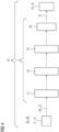
- FIG 4 shows a schematic structure of a further embodiment of the drive train 24 according to the invention, which can be used in a wind turbine 20 (not shown in detail) or an industrial application 26 (not shown in detail).
- the drive train 24 comprises a planetary gear 1 according to the invention, which is connected on the input side to a drive means 27 or a rotor 21 of the wind turbine 20 and to which a drive power 28 is thus supplied. In a wind turbine 20, this is done by means of a rotor shaft 22.
- the planetary gear 1 comprises three planetary stages 17, 18 and 29, which are arranged one behind the other, and a last gear stage 30 designed as a spur gear stage and are connected to one another according to the invention.
- the gear stages 17, 18, 29 and 30 deliver an output power 31 to a generator 23 or a mechanical application 32.
- FIG 5 the structure of an embodiment of an industrial application 26 is shown schematically, which has a drive means 33.
- the drive means 33 is designed to provide a drive power 28, which is transported to a transmission 1 according to the invention through a torque-transmitting connection.
- the transmission 1 is in turn connected to a mechanical application 32 in a torque-transmitting manner in order to transport an output power 31 to the mechanical application 32.
- the transmission 1 is designed as a planetary transmission 1 according to one of the embodiments outlined above.
Landscapes
- Engineering & Computer Science (AREA)
- General Engineering & Computer Science (AREA)
- Mechanical Engineering (AREA)
- Life Sciences & Earth Sciences (AREA)
- Sustainable Development (AREA)
- Sustainable Energy (AREA)
- Chemical & Material Sciences (AREA)
- Combustion & Propulsion (AREA)
- Retarders (AREA)
- Wind Motors (AREA)
Description
- Die Erfindung betrifft ein Planetengetriebe mit zumindest zwei Getriebestufen, wobei eine Sonnenwelle einer Planetenstufe zur Drehmomentübertragung über eine Kupplungsverzahnung mit einem Planetenträger einer auf diese Planetenstufe folgenden weiteren Planetenstufe verbunden ist. Ferner betrifft die Erfindung einen Antriebsstrang, in dem ein entsprechendes Planetengetriebe als Getriebe eingesetzt ist, eine Windkraftanlage, die mit einem solchen Antriebsstrang ausgerüstet ist, und eine Industrie-Applikation, die als Getriebe über ein solches Planetengetriebe verfügt.
- Aus der
DE 10 2016 202 533 A1 ist ein Planetengetriebe eingangs definierter Art bekannt. Das deutsche GebrauchsmusterDE 92 02 238 zeigt eine mittels einer Hirth-Verzahnung geteilte Welle, die ausgangsseitig mit einem Planetenträger eines Planetengetriebes verbunden ist. - Es ist eine Aufgabe der vorliegenden Erfindung, ein Planetengetriebe, einen Antriebsstrang, eine Windkraftanlage und eine Industrie-Applikation der eingangs genannten Art verbesserter Bauart zu schaffen.
- Zur Lösung dieser Aufgabe schafft die vorliegende Erfindung ein Planetengetriebe der eingangs genannten Art, das dadurch gekennzeichnet ist, dass es sich bei der Kupplungsverzahnung um eine Plankerbverzahnung handelt. Dank des erfindungsgemä-ßen Einsatzes einer solchen Plankerbverzahnung, die häufig auch als Stirnverzahnung bezeichnet wird, ist es möglich, bezogen auf eine Hauptdrehachse axial und/oder radial Bauraum einzusparen, was die Auslegung des Planetengetriebes basierend auf einer vom Kunden vorgegebenen Gesamtabmessung deutlich erleichtert.
- Erfindungsgemäß sind die die Plankerbverzahnung bildenden Stirnverzahnungen einerseits an einer Stirnseite der Sonnenwelle und andererseits an einer bezogen auf die Hautdrehachse axial an dieser Stirnseite der Sonnenwelle anliegenden Stirnseite des Planetenträgers vorgesehen. Bei dieser Variante sind die Sonnenwelle und der Planetenträger stirnseitig also direkt über die Plankerbverzahnung miteinander verbunden, was das Vorsehen einer Nabe an dieser Stelle überflüssig macht. Dies ermöglicht zum einen eine Bauraumeinsparung in bezogen auf die Hauptdrehachse axialer sowie radialer Richtung. Zum anderen ist die Herstellung des Planetenträgers sehr günstig, da für diesen wenig Material benötigt wird. Darüber hinaus ist er für die Bearbeitung sehr gut zugänglich.
- Die Sonnenwelle und der Planetenträger sind erfindungsgemäß unter Verwendung von sich bezogen auf die Hauptdrehachse axial erstreckenden Befestigungselementen aneinander befestigt, die bevorzugt in regelmäßigen Abständen zueinander positioniert sind. Vorteilhaft handelt es sich bei den Befestigungselementen um Befestigungsschrauben, die auf einem gemeinsamen Lochkreis positioniert sind. Mit derartigen Befestigungsschrauben wird eine besonders einfache und preiswerte axiale Sicherung der Verbindung von Sonnenwelle und Planetenträger realisiert.
- Erfindungsgemäß erstrecken sich die Befestigungselemente durch die Plankerbverzahnung. Auf diese Weise kann insbesondere dann bezogen auf die Hauptdrehachse radialer Bauraum eingespart werden, wenn die Sonnenwelle als Hohlwelle ausgebildet ist.
- Gemäß einer weiteren, nicht beanspruchten Variante des Planetengetriebes sind die die Plankerbverzahnung bildenden Stirnverzahnungen einerseits an einer Stirnseite einer drehfest am Außenumfang der Sonnenwelle befestigten Nabe und andererseits an einer axial an dieser Stirnseite der Sonnenwelle anliegenden Stirnseite des Planetenträgers vorgesehen. Bei dieser Variante sind die Sonnenwelle und der Planetenträger somit mittelbar über eine am Außenumfang der Sonnenwelle angeordnete Nabe miteinander verbunden, wobei die Plankerbverzahnung an der Nabe und an dem Planetenträger vorgesehen ist. Diese Bauart ermöglicht aufgrund der Trennung von Nabe und Planetenträger Dank der besseren Zugänglichkeit der Einzelkomponenten eine einfachere und preiswertere Herstellung und Bearbeitung derselben, ggf. auch unter Einsatz anderer Maschinen. Zudem können die Bearbeitung der Nabe und die des Planetenträgers getrennt beauftragt und so Bearbeiter ausgewählt werden, die für die jeweilige Bearbeitung optimal aufgestellt sind. Auch können Logistikkosten eingespart werden, da derzeit häufig der gesamte Planetenträger zur Bearbeitung des Nabenabschnitts über weite Strecken transportiert werden muss. Bevorzugt sind auch bei der zweiten Variante die Nabe und der Planetenträger unter Verwendung von sich bezogen auf die Hauptdrehachse axial erstreckenden Befestigungselementen aneinander befestigt, die insbesondere in regelmäßigen Abständen zueinander positioniert sind. Vorteilhaft handelt es sich bei den Befestigungselementen um Befestigungsschrauben, die auf einem gemeinsamen Lochkreis positioniert sind.
- Vorteilhaft erstrecken sich die Befestigungselemente auch hier durch die Plankerbverzahnung.
- Bevorzugt ist die Nabe über eine Kupplungsverzahnung mit der Sonnenwelle verbunden und insbesondere gegen bezogen auf die Hauptdrehachse axiale Verschiebung gesichert, wodurch sich ein einfacher und stabiler Aufbau ergibt.
- Weitere Merkmale und Vorteile der vorliegenden Erfindung werden anhand der nachfolgenden Beschreibung unter Bezugnahme auf die beiliegende Beschreibung deutlich. Darin ist
- FIG 1
- eine schematische Schnittansicht eines Bereiches eines Planetengetriebes gemäß einer Ausfuhrüngsform der vorliegenden Erfindung;
- FIG 2
- eine schematische Schnittansicht eines Bereiches eines Planetengetriebes gemäß einer nicht beanspruchten Ausführungsform;
- FIG 3
- eine geschnittene Seitenansicht einer Ausführungsform einer erfindungsgemäßen Windkraftanlage mit erfindungsgemäßem Planetengetriebe;
- FIG 4
- eine schematische Darstellung einer Ausführungsform eines erfindungsgemäßen Antriebsstrangs und
- FIG 5
- eine schematische Darstellung einer Ausführungsform einer erfindungsgemäßen Industrie-Applikation.
- Gleiche Bezugsziffern bezeichnen nachfolgend gleiche oder gleichartig ausgebildete Bauteile oder Bauteilbereiche.
-
FIG 1 zeigt Komponenten eines Planetengetriebes 1 gemäß einer Ausführungsform der vorliegenden Erfindung, genauer gesagt eine einteilig als Hohlwelle ausgebildete Sonnenwelle 2 einer Planetenstufe 17 und einen mit dieser verbundenen, vorliegend ebenfalls einteilig ausgebildeten Planetenträger 3 einer auf diese Planetenstufe 17 folgenden weiteren Planetenstufe 18. Die Sonnenwelle 2 ist an ihrem ersten freien Ende mit einer Sonnenverzahnung 4 versehen. Am zweiten freien Ende ist stirnseitig eine Stirnverzahnung 10 mit sich bezogen auf eine Hauptdrehachse 19 des Planetengetriebes 1 zumindest im Wesentlichen radial erstreckenden Zähnen ausgebildet, die einen ersten Teil einer Plankerbverzahnung definiert. Ferner ist am zweiten freien Ende der Sonnenwelle 2 stirnseitig eine Vielzahl von Gewindebohrungen 11 angeordnet, die sich in bezogen auf die Hauptdrehachse 19 axialer Richtung durch die Stirnverzahnung 10 erstrecken und vorliegend in gleichmäßigen Abständen entlang eines Lochkreises positioniert sind. Der Planetenträger 3 definiert an seinem ersten, der Sonnenwelle 2 zugewandten freien Ende eine Stirnverzahnung 12 mit sich bezogen auf die Hauptdrehachse 19 zumindest im Wesentlichen radial erstreckenden Zähnen, die entsprechend der Stirnverzahnung 10 der Sonnenwelle 2 ausgebildet ist und den zweiten Teil der Plankerbverzahnung definiert. Entsprechend kann die Stirnverzahnung 12 des Planetenträgers 3 bezogen auf die Hauptdrehachse 19 axial derart auf die Stirnverzahnung 10 der Sonnenwelle 2 aufgesetzt werden, dass die Sonnenwelle 2 und der Planetenträger 3 relativ zueinander zentriert, drehfest miteinander verbunden und bezogen auf die Hauptdrehachse 19 in radialer Richtung sowie in Umfangsrichtung gesichert werden. Im Bereich der Stirnverzahnung 12 sind den Gewindebohrungen 11 der Sonnenwelle 2 entsprechende Durchgangsbohrungen 13 ausgebildet, durch die von außen Befestigungselemente 14, vorliegend in Form von Befestigungsschrauben eingesetzt und in die Gewindebohrungen 11 geschraubt sind. Damit die Durchgangsbohrungen 13 des Planetenträgers 3 von außen zugänglich sind, sind die Stirnverzahnung 12 und die Durchgangsbohrungen 13 an einem bezogen auf die Hauptdrehachse 19 radial einwärts vorstehenden Ringflansch 15 vorgesehen, der derart bemessen ist, dass die Befestigungselemente 14 ausgehend vom dem der Sonnenwelle 2 abgewandten freien Ende des Planetenträgers 3 in die Durchgangsbohrungen 13 eingesetzt werden können. Im Übrigen weist der Planetenträger 3 einen Planetenradaufnahmeabschnitt 7 und einen Endabschnitt 8 auf. - Der in
FIG 1 dargestellte Aufbau zeichnet sich insbesondere dadurch aus, dass dank der Tatsache, dass die Drehmomentübertragung durch eine die Sonnenwelle 2 und den Planetenträger 3 miteinander verbindende Plankerbverzahnung erfolgt, bezogen auf die Hauptdrehachse 19 wenig radialer Bauraum benötigt wird. Darüber hinaus kann auch die Sonnenwelle 2 sehr kurz ausgeführt sein, um zusätzlich axialen Bauraum zu gewinnen. Noch ein weiterer Vorteil, der mit dem inFIG 1 dargestellten Aufbau einhergeht, besteht darin, dass sich der Planetenträger 3 einfach und preiswert herstellen und bearbeiten lässt. Dies liegt zum einen daran, dass Dank der Stirnverzahnung 10, 12 wenig Material benötigt wird. Zum anderen ist der Planetenträger 3 für eine maschinelle Bearbeitung aber auch sehr gut zugänglich. So lassen sich Ölkanäle oder dergleichen sehr einfach in den Planetenträger 3 einbringen. -
FIG 2 zeigt Komponenten eines Planetengetriebes 1 gemäß einer nicht beanspruchten Ausführungsform, genauer gesagt eine einteilig als Hohlwelle ausgebildete Sonnenwelle 2 einer Planetenstufe 17 und einen mit dieser mittelbar über eine Nabe 16 verbundenen, vorliegend ebenfalls einteilig ausgeführten Planetenträger 3 einer benachbarten weiteren Planetenstufe 18. Die Sonnenwelle 2 umfasst eine am ersten freien Ende angeordnete Sonnenverzahnung 4 und eine am zweiten freien Ende vorgesehene Außenumfangsverzahnung 5, deren Zähne sich bezogen auf die Hauptdrehachse 19 in axialer Richtung erstrecken. Die Nabe 16 ist ringförmig ausgebildet und ist entlang ihres Innenumfangs mit einer der Außenumfangsverzahnung 5 der Sonnenwelle 2 entsprechenden Innenumfangsverzahnung 9 versehen. Entsprechend lässt sich die Nabe 16 bezogen auf die Hauptdrehachse 19 axial auf die Sonnenwelle 2 aufschieben, wobei ihre Innenumfangsverzahnung 9 mit der Außenumfangsverzahnung 5 der Sonnenwelle 2 derart in Eingriff gebracht wird, dass die Nabe 16 bezogen auf die Hauptdrehachse 19 in radialer Richtung sowie in Umfangsrichtung an der Sonnenwelle 2 gesichert ist. Eine axiale Sicherung kann beispielsweise über einen Sicherungsring, über Befestigungsschrauben oder dergleichen erfolgen. Die Nabe 16 ist an ihrer zum Planetenträger 3 weisenden Stirnseite mit einer Stirnverzahnung 10 versehen, die einen ersten Teil einer Plankerbverzahnung definiert. Der zweite Teil der Plankerbverzahnung ist stirnseitig am Planetenträger 3 in Form einer Stirnverzahnung 12 ausgebildet. Die Befestigung des Planetenträgers 3 an der Nabe 16 erfolgt ähnlich wie bei der inFIG 2 beschriebenen ersten Ausführungsform über sich bezogen auf die Hauptdrehachse 19 axial erstreckende Befestigungselemente 13, vorliegend in Form von Befestigungsschrauben, die durch im Planetenträger 3 vorgesehene Durchgangsbohrungen 13 geführt und in Gewindebohrungen 11 geschraubt sind, die stirnseitig an der Nabe 16 im Bereich der Stirnverzahnung 10 ausgebildet sind. Entsprechend kann der Planetenträger 3 bezogen auf die Hauptdrehachse 19 axial auf die Sonnenwelle 2 aufgeschoben werden, bis die Stirnverzahnungen 12 des Planetenträgers und die Stirnverzahnung 10 der Nabe 16 miteinander in Eingriff gebracht werden, wodurch auch hier eine Sicherung in bezogen auf die Hauptdrehachse 19 radialer Richtung sowie in Umfangsrichtung erzielt wird. - Die in
FIG 2 dargestellte Bauart ermöglicht aufgrund der Trennung von Nabe 16 und Planetenträger 3 dank der besseren Zugänglichkeit der Einzelkomponenten eine einfache und preiswerte Herstellung und Bearbeitung derselben. Zudem können die Bearbeitung der Nabe 16 und die des Planetenträgers 3 getrennt beauftragt und so Bearbeiter ausgewählt werden, die für die jeweilige Bearbeitung optimal aufgestellt sind. Auch können Logistikkosten eingespart werden, da nicht der gesamte Planetenträger 3 über weite Strecken transportiert werden muss. - In
FIG 3 ist in einer geschnittenen Schrägansicht eine Ausführungsform einer erfindungsgemäßen Windkraftanlage 20 dargestellt. Die Windkraftanlage 20 umfasst einen Rotor 21, der durch Wind in Drehung versetzbar ist. Der Rotor 21 ist über eine Rotorwelle 22 mit einem erfindungsgemäßen Planetengetriebe 1 drehmomentübertragend verbunden. Das Planetengetriebe 1 wiederum ist drehmomentübertragend mit einem Generator 23 verbunden. Die Rotorwelle 22, das Planetengetriebe 1 und der Generator 23 gehören zu einem Antriebsstrang 24, der in einer Gondel 25 der Windkraftanlage 20 aufgenommen ist. Der Generator 23 weist zwei, drei oder vier Polpaare auf. Dank des Planetengetriebes 1 weist der Antriebsstrang 24 kleine Abmessungen auf, was beispielsweise die Montage der Windkraftanlage 20 erleichtert. Auch kann der Antriebsstrang 24 preiswert hergestellt werden. -
FIG 4 zeigt einen schematischen Aufbau einer weiteren Ausführungsform des erfindungsgemäßen Antriebsstrangs 24, der in einer nicht näher dargestellten Windkraftanlage 20 oder einer nicht näher dargestellten Industrie-Applikation 26 einsetzbar ist. Der Antriebsstrang 24 umfasst ein erfindungsgemäßes Planetengetriebe 1, das eingangsseitig mit einem Antriebsmittel 27 oder einem Rotor 21 der Windkraftanlage 20 verbunden ist und dem so eine Antriebsleistung 28 zugeführt wird. In einer Windkraftanlage 20 erfolgt dies mittels einer Rotorwelle 22. Das Planetengetriebe 1 umfasst vorliegend drei Planetenstufen 17, 18 und 29, die hintereinander angeordnet, und eine letzte als Stirnradstufe ausgebildete Getriebestufe 30 und erfindungsgemäß miteinander verbunden sind. Die Getriebestufen 17, 18, 29 und 30 geben eine Abtriebsleistung 31 an einen Generator 23 oder eine mechanische Anwendung 32 ab. - In
FIG 5 ist schematisch der Aufbau einer Ausführungsform einer Industrie-Applikation 26 dargestellt, die über ein Antriebsmittel 33 verfügt. Das Antriebsmittel 33 ist dazu ausgebildet, eine Antriebsleistung 28 bereitzustellen, die durch eine drehmomentübertragende Verbindung an ein erfindungsgemä-ßes Getriebe 1 transportiert wird. Das Getriebe 1 wiederum ist drehmomentübertragend mit einer mechanischen Anwendung 32 verbunden, um eine Abtriebsleistung 31 zur mechanischen Anwendung 32 zu transportieren. Das Getriebe 1 ist dazu als ein Planetengetriebe 1 nach einer der oben skizzierten Ausführungsformen ausgebildet.
Claims (4)
- Planetengetriebe (1) mit zumindest zwei Planetenstufen, wobei eine Sonnenwelle (2) einer Planetenstufe zur Drehmomentübertragung über eine Kupplungsverzahnung mit einem Planetenträger (3) einer auf diese Planetenstufe folgenden weiteren Planetenstufe verbunden ist, dadurch gekennzeichnet, dass es sich bei der Kupplungsverzahnung um eine Plankerbverzahnung handelt, wobei die die Plankerbverzahnung bildenden Stirnverzahnungen (10, 12) einerseits an einer Stirnseite der Sonnenwelle (2) und andererseits an einer bezogen auf eine Hauptdrehachse (19) axial an dieser Stirnseite der Sonnenwelle (2) anliegenden Stirnseite des Planetenträgers (3) vorgesehen sind, wobei die Sonnenwelle (2) und der Planetenträger (3) unter Verwendung von sich bezogen auf die Hauptdrehachse (19) axial erstreckenden Befestigungselementen (14) aneinander befestigt sind, die bevorzugt in regelmäßigen Abständen zueinander positioniert sind, wobei sich die Befestigungselemente (14) durch die Plankerbverzahnung erstrecken.
- Antriebsstrang (24), umfassend eine Rotorwelle (22), die drehmomentübertragend mit einem Getriebe des Antriebsstranges (24) verbunden ist, das wiederum drehmomentübertragend mit einem Generator (23) des Antriebsstranges (24) verbunden ist, dadurch gekennzeichnet, dass das Getriebe als Planetengetriebe (1) nach Anspruch 1 ausgebildet ist.
- Windkraftanlage (20), umfassend einen Rotor (21), der an einer Gondel (25) angebracht ist, wobei in der Gondel (25) ein Antriebsstrang (24) angeordnet ist, der drehmomentübertragend mit dem Rotor (21) verbunden ist, dadurch gekennzeichnet, dass der Antriebsstrang (24) nach Anspruch 2 ausgebildet ist.
- Industrie-Applikation (26), umfassend ein Antriebsmittel (27), das mit einem Getriebe (1) der Industrie-Applikation drehrmomentübertragend verbunden ist, das mit einer mechanischen Anwendung (32) der Industrie-Applikation (26) drehmomentübertragend gekoppelt ist, dadurch gekennzeichnet, dass das Getriebe (1) als Planetengetriebe (1) nach Anspruch 1 ausgebildet ist.
Priority Applications (4)
| Application Number | Priority Date | Filing Date | Title |
|---|---|---|---|
| ES19171876T ES2988757T3 (es) | 2019-04-30 | 2019-04-30 | Engranaje planetario |
| EP19171876.6A EP3734112B1 (de) | 2019-04-30 | 2019-04-30 | Planetengetriebe |
| CN202010328048.0A CN111852786B (zh) | 2019-04-30 | 2020-04-23 | 行星传动装置、传动系、风力涡轮机及工业应用装置 |
| US16/863,407 US11209071B2 (en) | 2019-04-30 | 2020-04-30 | Planetary transmission |
Applications Claiming Priority (1)
| Application Number | Priority Date | Filing Date | Title |
|---|---|---|---|
| EP19171876.6A EP3734112B1 (de) | 2019-04-30 | 2019-04-30 | Planetengetriebe |
Publications (2)
| Publication Number | Publication Date |
|---|---|
| EP3734112A1 EP3734112A1 (de) | 2020-11-04 |
| EP3734112B1 true EP3734112B1 (de) | 2024-09-11 |
Family
ID=66349317
Family Applications (1)
| Application Number | Title | Priority Date | Filing Date |
|---|---|---|---|
| EP19171876.6A Active EP3734112B1 (de) | 2019-04-30 | 2019-04-30 | Planetengetriebe |
Country Status (4)
| Country | Link |
|---|---|
| US (1) | US11209071B2 (de) |
| EP (1) | EP3734112B1 (de) |
| CN (1) | CN111852786B (de) |
| ES (1) | ES2988757T3 (de) |
Families Citing this family (5)
| Publication number | Priority date | Publication date | Assignee | Title |
|---|---|---|---|---|
| DE102022200896A1 (de) | 2022-01-27 | 2023-03-16 | Zf Friedrichshafen Ag | Anordnung mit Planetenstufen und Passverzahnung |
| DE102022109498A1 (de) | 2022-04-20 | 2023-10-26 | Schaeffler Technologies AG & Co. KG | Getriebevorrichtung mit einem Planetentrieb und mit einer Schmiervorrichtung |
| CN218236092U (zh) * | 2022-10-21 | 2023-01-06 | 采埃孚(天津)风电有限公司 | 一种风电机齿轮箱连接结构及齿轮箱 |
| EP4428382A1 (de) * | 2023-03-06 | 2024-09-11 | Flender GmbH | Getriebelagerung für eine windkraftanlage |
| EP4653716A1 (de) * | 2024-05-21 | 2025-11-26 | Flender GmbH | Welle-nabe-verbindung mit axialsicherung |
Family Cites Families (16)
| Publication number | Priority date | Publication date | Assignee | Title |
|---|---|---|---|---|
| DE9202238U1 (de) * | 1992-02-21 | 1992-04-23 | Heinrich Desch Kg, 5760 Arnsberg | Maschinenantriebswelle mit angekuppeltem Planetenträger |
| US8753243B2 (en) | 2006-08-15 | 2014-06-17 | United Technologies Corporation | Ring gear mounting arrangement with oil scavenge scheme |
| FR2941754B1 (fr) * | 2009-01-30 | 2011-01-14 | Eurocopter France | Couplage a rattrapage de jeu, rotor et aeronef a voilure tournante |
| EP2270333A1 (de) * | 2009-06-29 | 2011-01-05 | Hansen Transmissions International, Naamloze Vennotschap | Planetenradgetriebeeinheit mit Verriegelungsmechanismus für die Planetenwelle |
| TWI490090B (zh) * | 2009-07-31 | 2015-07-01 | Stanley D Winnard | 能轉動的棘輪聯接元件、折疊式棘輪撬棍以及折疊式外殼 |
| GB2490114B (en) * | 2011-04-18 | 2013-06-12 | Rolls Royce Plc | Rotational assembly |
| US9790997B2 (en) * | 2014-09-17 | 2017-10-17 | Electro-Motive Diesel, Inc. | Assembly for preventing abuse of a pump mounted to a driver equipment |
| JP6537915B2 (ja) * | 2015-07-27 | 2019-07-03 | Ntn株式会社 | ピッチ円錐角測定方法及び測定装置 |
| US20170082150A1 (en) * | 2015-09-17 | 2017-03-23 | Ford Global Technologies, Llc | Face-spline drive element with axial retainer mechanism |
| DE102015217906A1 (de) * | 2015-09-18 | 2017-03-23 | Zf Friedrichshafen Ag | Mehrstufiges Planetengetriebe für eine Windkraftanlage mit spezieller Schmierölführung |
| DE102016202533A1 (de) * | 2016-02-18 | 2017-08-24 | Zf Friedrichshafen Ag | Schmierung einer Steckverzahnung |
| CN105697667A (zh) * | 2016-03-22 | 2016-06-22 | 西北工业大学 | 一种锥齿轮行星机构无级变速传动装置 |
| DE102016012947A1 (de) * | 2016-10-28 | 2018-05-03 | Neumayer Tekfor Engineering Gmbh | Verbindungsanordnung zum Verbinden einer Welle mit einem Bauteil |
| JP2018079498A (ja) * | 2016-11-17 | 2018-05-24 | Ntn株式会社 | 車輪用軸受のスプライン加工方法 |
| CN108327529A (zh) * | 2018-03-30 | 2018-07-27 | 重庆青山工业有限责任公司 | 混合动力汽车的后电驱动总成 |
| US11821468B2 (en) * | 2018-11-08 | 2023-11-21 | Pratt & Whitney Canada Corp. | Positioning device and method for shafts |
-
2019
- 2019-04-30 EP EP19171876.6A patent/EP3734112B1/de active Active
- 2019-04-30 ES ES19171876T patent/ES2988757T3/es active Active
-
2020
- 2020-04-23 CN CN202010328048.0A patent/CN111852786B/zh active Active
- 2020-04-30 US US16/863,407 patent/US11209071B2/en active Active
Also Published As
| Publication number | Publication date |
|---|---|
| EP3734112A1 (de) | 2020-11-04 |
| US11209071B2 (en) | 2021-12-28 |
| ES2988757T3 (es) | 2024-11-21 |
| CN111852786A (zh) | 2020-10-30 |
| US20200347914A1 (en) | 2020-11-05 |
| CN111852786B (zh) | 2023-04-28 |
Similar Documents
| Publication | Publication Date | Title |
|---|---|---|
| EP3734112B1 (de) | Planetengetriebe | |
| EP3612402B1 (de) | Getriebe für ein kraftfahrzeug, insbesondere für ein seriell/paralleles hybridfahrzeug | |
| EP3789625B1 (de) | Flanschanordnung, getriebe, elektromotor, windkraftanlage und industrie-applikation | |
| DE102007011895B4 (de) | Stirnraddiffernzial und Überlagerungsdifferenzial mit dem Stirnraddifferenzial | |
| EP3322908B1 (de) | Getriebe mit anlaufscheibe zur axialen sicherung von wälzkörpern eines lagers | |
| DE102015219222A1 (de) | Planetengetriebe mit Leistungsverzweigung in der ersten Getriebestufe | |
| DE102007011894B4 (de) | Stirnraddifferenzial und Überlagerungsdifferenzial mit dem Stirnraddifferenzial | |
| DE102019121275A1 (de) | Getriebeanordnung | |
| DE102013225553A1 (de) | Welle-Nabe-Verbindung | |
| WO2019214763A1 (de) | Anordnung zur fliehkraftsicherung zumindest eines auf einer rotorwelle einer elektrischen maschine zur lagesicherung axial festgesetzten sicherungsrings und verwendung einer solchen anordnung | |
| WO2019214762A1 (de) | Anordnung zur axialen lagesicherung eines sonnenrads einer planetengetriebestufe auf einer rotorwelle einer elektrischen maschine und verwendung einer solchen anordnung | |
| EP1375953A2 (de) | Mehrteilige Bremsscheibe | |
| EP3094863B1 (de) | Lageranordnung für ein planetengetriebe einer windkraftanlage | |
| DE102015011074A1 (de) | Getriebe mit zumindest einer Exzenterwelle | |
| DE102017223092A1 (de) | Sonnenrad-Planetenträger-Anordnung für ein Planetengetriebe | |
| DE102014226046B4 (de) | Wolfrom-Getriebe mit dreifach verzahnten Planeten für eine Windkraftanlage und Verfahren zur Montage von Lagern eines solchen Getriebes | |
| EP2551552A1 (de) | Getriebeanordnung | |
| EP2238370B1 (de) | Getriebe | |
| EP2551553A1 (de) | Getriebeanordnung | |
| EP3139067B1 (de) | Planetengetriebe | |
| DE102011076656A1 (de) | Baugruppe eines Getriebes | |
| EP3734098A1 (de) | Wälzlager und vorrichtung mit einem solchen wälzlager | |
| DE102010051209A1 (de) | Rotorlager einer Windkraftanlage | |
| WO2025219017A1 (de) | Welle-nabe-verbindung, insbesondere eines getriebemotors | |
| WO2025242647A1 (de) | Welle-nabe-verbindung mit axialsicherung |
Legal Events
| Date | Code | Title | Description |
|---|---|---|---|
| PUAI | Public reference made under article 153(3) epc to a published international application that has entered the european phase |
Free format text: ORIGINAL CODE: 0009012 |
|
| STAA | Information on the status of an ep patent application or granted ep patent |
Free format text: STATUS: THE APPLICATION HAS BEEN PUBLISHED |
|
| AK | Designated contracting states |
Kind code of ref document: A1 Designated state(s): AL AT BE BG CH CY CZ DE DK EE ES FI FR GB GR HR HU IE IS IT LI LT LU LV MC MK MT NL NO PL PT RO RS SE SI SK SM TR |
|
| AX | Request for extension of the european patent |
Extension state: BA ME |
|
| STAA | Information on the status of an ep patent application or granted ep patent |
Free format text: STATUS: REQUEST FOR EXAMINATION WAS MADE |
|
| 17P | Request for examination filed |
Effective date: 20210504 |
|
| RBV | Designated contracting states (corrected) |
Designated state(s): AL AT BE BG CH CY CZ DE DK EE ES FI FR GB GR HR HU IE IS IT LI LT LU LV MC MK MT NL NO PL PT RO RS SE SI SK SM TR |
|
| STAA | Information on the status of an ep patent application or granted ep patent |
Free format text: STATUS: EXAMINATION IS IN PROGRESS |
|
| 17Q | First examination report despatched |
Effective date: 20220621 |
|
| GRAP | Despatch of communication of intention to grant a patent |
Free format text: ORIGINAL CODE: EPIDOSNIGR1 |
|
| STAA | Information on the status of an ep patent application or granted ep patent |
Free format text: STATUS: GRANT OF PATENT IS INTENDED |
|
| RIC1 | Information provided on ipc code assigned before grant |
Ipc: F16D 1/10 20060101ALN20240429BHEP Ipc: F16H 57/02 20120101ALN20240429BHEP Ipc: F16D 1/076 20060101ALI20240429BHEP Ipc: F16D 1/033 20060101ALI20240429BHEP Ipc: F16H 57/08 20060101ALI20240429BHEP Ipc: F16H 1/46 20060101AFI20240429BHEP |
|
| INTG | Intention to grant announced |
Effective date: 20240516 |
|
| GRAS | Grant fee paid |
Free format text: ORIGINAL CODE: EPIDOSNIGR3 |
|
| GRAA | (expected) grant |
Free format text: ORIGINAL CODE: 0009210 |
|
| STAA | Information on the status of an ep patent application or granted ep patent |
Free format text: STATUS: THE PATENT HAS BEEN GRANTED |
|
| AK | Designated contracting states |
Kind code of ref document: B1 Designated state(s): AL AT BE BG CH CY CZ DE DK EE ES FI FR GB GR HR HU IE IS IT LI LT LU LV MC MK MT NL NO PL PT RO RS SE SI SK SM TR |
|
| REG | Reference to a national code |
Ref country code: GB Ref legal event code: FG4D Free format text: NOT ENGLISH |
|
| REG | Reference to a national code |
Ref country code: CH Ref legal event code: EP |
|
| REG | Reference to a national code |
Ref country code: DE Ref legal event code: R096 Ref document number: 502019012085 Country of ref document: DE |
|
| REG | Reference to a national code |
Ref country code: IE Ref legal event code: FG4D Free format text: LANGUAGE OF EP DOCUMENT: GERMAN |
|
| REG | Reference to a national code |
Ref country code: ES Ref legal event code: FG2A Ref document number: 2988757 Country of ref document: ES Kind code of ref document: T3 Effective date: 20241121 |
|
| REG | Reference to a national code |
Ref country code: LT Ref legal event code: MG9D |
|
| PG25 | Lapsed in a contracting state [announced via postgrant information from national office to epo] |
Ref country code: NO Free format text: LAPSE BECAUSE OF FAILURE TO SUBMIT A TRANSLATION OF THE DESCRIPTION OR TO PAY THE FEE WITHIN THE PRESCRIBED TIME-LIMIT Effective date: 20241211 |
|
| REG | Reference to a national code |
Ref country code: NL Ref legal event code: MP Effective date: 20240911 |
|
| PG25 | Lapsed in a contracting state [announced via postgrant information from national office to epo] |
Ref country code: GR Free format text: LAPSE BECAUSE OF FAILURE TO SUBMIT A TRANSLATION OF THE DESCRIPTION OR TO PAY THE FEE WITHIN THE PRESCRIBED TIME-LIMIT Effective date: 20241212 Ref country code: FI Free format text: LAPSE BECAUSE OF FAILURE TO SUBMIT A TRANSLATION OF THE DESCRIPTION OR TO PAY THE FEE WITHIN THE PRESCRIBED TIME-LIMIT Effective date: 20240911 |
|
| PG25 | Lapsed in a contracting state [announced via postgrant information from national office to epo] |
Ref country code: BG Free format text: LAPSE BECAUSE OF FAILURE TO SUBMIT A TRANSLATION OF THE DESCRIPTION OR TO PAY THE FEE WITHIN THE PRESCRIBED TIME-LIMIT Effective date: 20240911 |
|
| PG25 | Lapsed in a contracting state [announced via postgrant information from national office to epo] |
Ref country code: LV Free format text: LAPSE BECAUSE OF FAILURE TO SUBMIT A TRANSLATION OF THE DESCRIPTION OR TO PAY THE FEE WITHIN THE PRESCRIBED TIME-LIMIT Effective date: 20240911 |
|
| PG25 | Lapsed in a contracting state [announced via postgrant information from national office to epo] |
Ref country code: HR Free format text: LAPSE BECAUSE OF FAILURE TO SUBMIT A TRANSLATION OF THE DESCRIPTION OR TO PAY THE FEE WITHIN THE PRESCRIBED TIME-LIMIT Effective date: 20240911 |
|
| PG25 | Lapsed in a contracting state [announced via postgrant information from national office to epo] |
Ref country code: RS Free format text: LAPSE BECAUSE OF FAILURE TO SUBMIT A TRANSLATION OF THE DESCRIPTION OR TO PAY THE FEE WITHIN THE PRESCRIBED TIME-LIMIT Effective date: 20241211 |
|
| PG25 | Lapsed in a contracting state [announced via postgrant information from national office to epo] |
Ref country code: RS Free format text: LAPSE BECAUSE OF FAILURE TO SUBMIT A TRANSLATION OF THE DESCRIPTION OR TO PAY THE FEE WITHIN THE PRESCRIBED TIME-LIMIT Effective date: 20241211 Ref country code: NO Free format text: LAPSE BECAUSE OF FAILURE TO SUBMIT A TRANSLATION OF THE DESCRIPTION OR TO PAY THE FEE WITHIN THE PRESCRIBED TIME-LIMIT Effective date: 20241211 Ref country code: LV Free format text: LAPSE BECAUSE OF FAILURE TO SUBMIT A TRANSLATION OF THE DESCRIPTION OR TO PAY THE FEE WITHIN THE PRESCRIBED TIME-LIMIT Effective date: 20240911 Ref country code: HR Free format text: LAPSE BECAUSE OF FAILURE TO SUBMIT A TRANSLATION OF THE DESCRIPTION OR TO PAY THE FEE WITHIN THE PRESCRIBED TIME-LIMIT Effective date: 20240911 Ref country code: GR Free format text: LAPSE BECAUSE OF FAILURE TO SUBMIT A TRANSLATION OF THE DESCRIPTION OR TO PAY THE FEE WITHIN THE PRESCRIBED TIME-LIMIT Effective date: 20241212 Ref country code: FI Free format text: LAPSE BECAUSE OF FAILURE TO SUBMIT A TRANSLATION OF THE DESCRIPTION OR TO PAY THE FEE WITHIN THE PRESCRIBED TIME-LIMIT Effective date: 20240911 Ref country code: BG Free format text: LAPSE BECAUSE OF FAILURE TO SUBMIT A TRANSLATION OF THE DESCRIPTION OR TO PAY THE FEE WITHIN THE PRESCRIBED TIME-LIMIT Effective date: 20240911 |
|
| PG25 | Lapsed in a contracting state [announced via postgrant information from national office to epo] |
Ref country code: NL Free format text: LAPSE BECAUSE OF FAILURE TO SUBMIT A TRANSLATION OF THE DESCRIPTION OR TO PAY THE FEE WITHIN THE PRESCRIBED TIME-LIMIT Effective date: 20240911 |
|
| PG25 | Lapsed in a contracting state [announced via postgrant information from national office to epo] |
Ref country code: IS Free format text: LAPSE BECAUSE OF FAILURE TO SUBMIT A TRANSLATION OF THE DESCRIPTION OR TO PAY THE FEE WITHIN THE PRESCRIBED TIME-LIMIT Effective date: 20250111 Ref country code: PT Free format text: LAPSE BECAUSE OF FAILURE TO SUBMIT A TRANSLATION OF THE DESCRIPTION OR TO PAY THE FEE WITHIN THE PRESCRIBED TIME-LIMIT Effective date: 20250113 |
|
| PG25 | Lapsed in a contracting state [announced via postgrant information from national office to epo] |
Ref country code: SM Free format text: LAPSE BECAUSE OF FAILURE TO SUBMIT A TRANSLATION OF THE DESCRIPTION OR TO PAY THE FEE WITHIN THE PRESCRIBED TIME-LIMIT Effective date: 20240911 Ref country code: RO Free format text: LAPSE BECAUSE OF FAILURE TO SUBMIT A TRANSLATION OF THE DESCRIPTION OR TO PAY THE FEE WITHIN THE PRESCRIBED TIME-LIMIT Effective date: 20240911 |
|
| PG25 | Lapsed in a contracting state [announced via postgrant information from national office to epo] |
Ref country code: EE Free format text: LAPSE BECAUSE OF FAILURE TO SUBMIT A TRANSLATION OF THE DESCRIPTION OR TO PAY THE FEE WITHIN THE PRESCRIBED TIME-LIMIT Effective date: 20240911 |
|
| PG25 | Lapsed in a contracting state [announced via postgrant information from national office to epo] |
Ref country code: CZ Free format text: LAPSE BECAUSE OF FAILURE TO SUBMIT A TRANSLATION OF THE DESCRIPTION OR TO PAY THE FEE WITHIN THE PRESCRIBED TIME-LIMIT Effective date: 20240911 Ref country code: PL Free format text: LAPSE BECAUSE OF FAILURE TO SUBMIT A TRANSLATION OF THE DESCRIPTION OR TO PAY THE FEE WITHIN THE PRESCRIBED TIME-LIMIT Effective date: 20240911 |
|
| PG25 | Lapsed in a contracting state [announced via postgrant information from national office to epo] |
Ref country code: SK Free format text: LAPSE BECAUSE OF FAILURE TO SUBMIT A TRANSLATION OF THE DESCRIPTION OR TO PAY THE FEE WITHIN THE PRESCRIBED TIME-LIMIT Effective date: 20240911 Ref country code: IT Free format text: LAPSE BECAUSE OF FAILURE TO SUBMIT A TRANSLATION OF THE DESCRIPTION OR TO PAY THE FEE WITHIN THE PRESCRIBED TIME-LIMIT Effective date: 20240911 |
|
| REG | Reference to a national code |
Ref country code: DE Ref legal event code: R097 Ref document number: 502019012085 Country of ref document: DE |
|
| PGFP | Annual fee paid to national office [announced via postgrant information from national office to epo] |
Ref country code: DE Payment date: 20250429 Year of fee payment: 7 |
|
| PG25 | Lapsed in a contracting state [announced via postgrant information from national office to epo] |
Ref country code: DK Free format text: LAPSE BECAUSE OF FAILURE TO SUBMIT A TRANSLATION OF THE DESCRIPTION OR TO PAY THE FEE WITHIN THE PRESCRIBED TIME-LIMIT Effective date: 20240911 |
|
| PGFP | Annual fee paid to national office [announced via postgrant information from national office to epo] |
Ref country code: ES Payment date: 20250530 Year of fee payment: 7 |
|
| PGFP | Annual fee paid to national office [announced via postgrant information from national office to epo] |
Ref country code: BE Payment date: 20250418 Year of fee payment: 7 |
|
| PLBE | No opposition filed within time limit |
Free format text: ORIGINAL CODE: 0009261 |
|
| STAA | Information on the status of an ep patent application or granted ep patent |
Free format text: STATUS: NO OPPOSITION FILED WITHIN TIME LIMIT |
|
| 26N | No opposition filed |
Effective date: 20250612 |
|
| PG25 | Lapsed in a contracting state [announced via postgrant information from national office to epo] |
Ref country code: SE Free format text: LAPSE BECAUSE OF FAILURE TO SUBMIT A TRANSLATION OF THE DESCRIPTION OR TO PAY THE FEE WITHIN THE PRESCRIBED TIME-LIMIT Effective date: 20240911 |
|
| REG | Reference to a national code |
Ref country code: CH Ref legal event code: H13 Free format text: ST27 STATUS EVENT CODE: U-0-0-H10-H13 (AS PROVIDED BY THE NATIONAL OFFICE) Effective date: 20251125 |
|
| PG25 | Lapsed in a contracting state [announced via postgrant information from national office to epo] |
Ref country code: LU Free format text: LAPSE BECAUSE OF NON-PAYMENT OF DUE FEES Effective date: 20250430 |
|
| PG25 | Lapsed in a contracting state [announced via postgrant information from national office to epo] |
Ref country code: MC Free format text: LAPSE BECAUSE OF FAILURE TO SUBMIT A TRANSLATION OF THE DESCRIPTION OR TO PAY THE FEE WITHIN THE PRESCRIBED TIME-LIMIT Effective date: 20240911 |
|
| GBPC | Gb: european patent ceased through non-payment of renewal fee |
Effective date: 20250430 |
|
| PG25 | Lapsed in a contracting state [announced via postgrant information from national office to epo] |
Ref country code: GB Free format text: LAPSE BECAUSE OF NON-PAYMENT OF DUE FEES Effective date: 20250430 |
|
| PG25 | Lapsed in a contracting state [announced via postgrant information from national office to epo] |
Ref country code: FR Free format text: LAPSE BECAUSE OF NON-PAYMENT OF DUE FEES Effective date: 20250430 |
|
| PG25 | Lapsed in a contracting state [announced via postgrant information from national office to epo] |
Ref country code: CH Free format text: LAPSE BECAUSE OF NON-PAYMENT OF DUE FEES Effective date: 20250430 |
|
| PG25 | Lapsed in a contracting state [announced via postgrant information from national office to epo] |
Ref country code: IE Free format text: LAPSE BECAUSE OF NON-PAYMENT OF DUE FEES Effective date: 20250430 |