EP3734336A1 - Fibre optique et dispositif laser - Google Patents
Fibre optique et dispositif laser Download PDFInfo
- Publication number
- EP3734336A1 EP3734336A1 EP18893405.3A EP18893405A EP3734336A1 EP 3734336 A1 EP3734336 A1 EP 3734336A1 EP 18893405 A EP18893405 A EP 18893405A EP 3734336 A1 EP3734336 A1 EP 3734336A1
- Authority
- EP
- European Patent Office
- Prior art keywords
- light
- mode
- optical fiber
- wavelength
- core
- Prior art date
- Legal status (The legal status is an assumption and is not a legal conclusion. Google has not performed a legal analysis and makes no representation as to the accuracy of the status listed.)
- Pending
Links
- 239000013307 optical fiber Substances 0.000 title claims abstract description 325
- 230000001902 propagating effect Effects 0.000 claims abstract description 57
- 101710121003 Oxygen-evolving enhancer protein 3, chloroplastic Proteins 0.000 claims description 91
- 229910052769 Ytterbium Inorganic materials 0.000 claims description 16
- NAWDYIZEMPQZHO-UHFFFAOYSA-N ytterbium Chemical compound [Yb] NAWDYIZEMPQZHO-UHFFFAOYSA-N 0.000 claims description 16
- 230000003321 amplification Effects 0.000 description 62
- 238000003199 nucleic acid amplification method Methods 0.000 description 62
- 230000006866 deterioration Effects 0.000 description 41
- 238000001069 Raman spectroscopy Methods 0.000 description 34
- 238000010586 diagram Methods 0.000 description 33
- 238000005452 bending Methods 0.000 description 25
- 239000000835 fiber Substances 0.000 description 21
- 238000005086 pumping Methods 0.000 description 15
- 239000002019 doping agent Substances 0.000 description 10
- 238000005259 measurement Methods 0.000 description 10
- 239000010453 quartz Substances 0.000 description 10
- VYPSYNLAJGMNEJ-UHFFFAOYSA-N silicon dioxide Inorganic materials O=[Si]=O VYPSYNLAJGMNEJ-UHFFFAOYSA-N 0.000 description 10
- 230000003287 optical effect Effects 0.000 description 9
- 238000004088 simulation Methods 0.000 description 9
- 239000011347 resin Substances 0.000 description 8
- 229920005989 resin Polymers 0.000 description 8
- 238000000034 method Methods 0.000 description 7
- 239000011247 coating layer Substances 0.000 description 5
- 230000000644 propagated effect Effects 0.000 description 4
- PXGOKWXKJXAPGV-UHFFFAOYSA-N Fluorine Chemical compound FF PXGOKWXKJXAPGV-UHFFFAOYSA-N 0.000 description 3
- 230000008033 biological extinction Effects 0.000 description 3
- 239000011248 coating agent Substances 0.000 description 3
- 238000000576 coating method Methods 0.000 description 3
- 229910052731 fluorine Inorganic materials 0.000 description 3
- 239000011737 fluorine Substances 0.000 description 3
- 230000007423 decrease Effects 0.000 description 2
- 229910052732 germanium Inorganic materials 0.000 description 2
- GNPVGFCGXDBREM-UHFFFAOYSA-N germanium atom Chemical compound [Ge] GNPVGFCGXDBREM-UHFFFAOYSA-N 0.000 description 2
- 238000003754 machining Methods 0.000 description 2
- 239000000463 material Substances 0.000 description 2
- 239000004065 semiconductor Substances 0.000 description 2
- 229910001218 Gallium arsenide Inorganic materials 0.000 description 1
- 206010034972 Photosensitivity reaction Diseases 0.000 description 1
- 238000006243 chemical reaction Methods 0.000 description 1
- 230000005684 electric field Effects 0.000 description 1
- 239000011521 glass Substances 0.000 description 1
- 230000001678 irradiating effect Effects 0.000 description 1
- NLYAJNPCOHFWQQ-UHFFFAOYSA-N kaolin Chemical group O.O.O=[Al]O[Si](=O)O[Si](=O)O[Al]=O NLYAJNPCOHFWQQ-UHFFFAOYSA-N 0.000 description 1
- 230000010355 oscillation Effects 0.000 description 1
- 230000036211 photosensitivity Effects 0.000 description 1
- 229910052761 rare earth metal Inorganic materials 0.000 description 1
Images


Classifications
-
- G—PHYSICS
- G02—OPTICS
- G02B—OPTICAL ELEMENTS, SYSTEMS OR APPARATUS
- G02B6/00—Light guides; Structural details of arrangements comprising light guides and other optical elements, e.g. couplings
- G02B6/02—Optical fibres with cladding with or without a coating
- G02B6/02047—Dual mode fibre
-
- G—PHYSICS
- G02—OPTICS
- G02B—OPTICAL ELEMENTS, SYSTEMS OR APPARATUS
- G02B6/00—Light guides; Structural details of arrangements comprising light guides and other optical elements, e.g. couplings
- G02B6/02—Optical fibres with cladding with or without a coating
- G02B6/02004—Optical fibres with cladding with or without a coating characterised by the core effective area or mode field radius
- G02B6/02009—Large effective area or mode field radius, e.g. to reduce nonlinear effects in single mode fibres
- G02B6/02014—Effective area greater than 60 square microns in the C band, i.e. 1530-1565 nm
- G02B6/02019—Effective area greater than 90 square microns in the C band, i.e. 1530-1565 nm
-
- G—PHYSICS
- G02—OPTICS
- G02B—OPTICAL ELEMENTS, SYSTEMS OR APPARATUS
- G02B6/00—Light guides; Structural details of arrangements comprising light guides and other optical elements, e.g. couplings
- G02B6/02—Optical fibres with cladding with or without a coating
- G02B6/036—Optical fibres with cladding with or without a coating core or cladding comprising multiple layers
- G02B6/03616—Optical fibres characterised both by the number of different refractive index layers around the central core segment, i.e. around the innermost high index core layer, and their relative refractive index difference
-
- H—ELECTRICITY
- H01—ELECTRIC ELEMENTS
- H01S—DEVICES USING THE PROCESS OF LIGHT AMPLIFICATION BY STIMULATED EMISSION OF RADIATION [LASER] TO AMPLIFY OR GENERATE LIGHT; DEVICES USING STIMULATED EMISSION OF ELECTROMAGNETIC RADIATION IN WAVE RANGES OTHER THAN OPTICAL
- H01S3/00—Lasers, i.e. devices using stimulated emission of electromagnetic radiation in the infrared, visible or ultraviolet wave range
- H01S3/05—Construction or shape of optical resonators; Accommodation of active medium therein; Shape of active medium
- H01S3/08—Construction or shape of optical resonators or components thereof
- H01S3/08018—Mode suppression
- H01S3/0804—Transverse or lateral modes
- H01S3/08045—Single-mode emission
-
- G—PHYSICS
- G02—OPTICS
- G02B—OPTICAL ELEMENTS, SYSTEMS OR APPARATUS
- G02B6/00—Light guides; Structural details of arrangements comprising light guides and other optical elements, e.g. couplings
- G02B6/02—Optical fibres with cladding with or without a coating
- G02B6/02004—Optical fibres with cladding with or without a coating characterised by the core effective area or mode field radius
- G02B6/02009—Large effective area or mode field radius, e.g. to reduce nonlinear effects in single mode fibres
- G02B6/02023—Based on higher order modes, i.e. propagating modes other than the LP01 or HE11 fundamental mode
-
- G—PHYSICS
- G02—OPTICS
- G02B—OPTICAL ELEMENTS, SYSTEMS OR APPARATUS
- G02B6/00—Light guides; Structural details of arrangements comprising light guides and other optical elements, e.g. couplings
- G02B6/02—Optical fibres with cladding with or without a coating
- G02B6/036—Optical fibres with cladding with or without a coating core or cladding comprising multiple layers
- G02B6/03616—Optical fibres characterised both by the number of different refractive index layers around the central core segment, i.e. around the innermost high index core layer, and their relative refractive index difference
- G02B6/03622—Optical fibres characterised both by the number of different refractive index layers around the central core segment, i.e. around the innermost high index core layer, and their relative refractive index difference having 2 layers only
- G02B6/03633—Optical fibres characterised both by the number of different refractive index layers around the central core segment, i.e. around the innermost high index core layer, and their relative refractive index difference having 2 layers only arranged - -
-
- H—ELECTRICITY
- H01—ELECTRIC ELEMENTS
- H01S—DEVICES USING THE PROCESS OF LIGHT AMPLIFICATION BY STIMULATED EMISSION OF RADIATION [LASER] TO AMPLIFY OR GENERATE LIGHT; DEVICES USING STIMULATED EMISSION OF ELECTROMAGNETIC RADIATION IN WAVE RANGES OTHER THAN OPTICAL
- H01S2301/00—Functional characteristics
- H01S2301/03—Suppression of nonlinear conversion, e.g. specific design to suppress for example stimulated brillouin scattering [SBS], mainly in optical fibres in combination with multimode pumping
-
- H—ELECTRICITY
- H01—ELECTRIC ELEMENTS
- H01S—DEVICES USING THE PROCESS OF LIGHT AMPLIFICATION BY STIMULATED EMISSION OF RADIATION [LASER] TO AMPLIFY OR GENERATE LIGHT; DEVICES USING STIMULATED EMISSION OF ELECTROMAGNETIC RADIATION IN WAVE RANGES OTHER THAN OPTICAL
- H01S3/00—Lasers, i.e. devices using stimulated emission of electromagnetic radiation in the infrared, visible or ultraviolet wave range
- H01S3/05—Construction or shape of optical resonators; Accommodation of active medium therein; Shape of active medium
- H01S3/06—Construction or shape of active medium
- H01S3/063—Waveguide lasers, i.e. whereby the dimensions of the waveguide are of the order of the light wavelength
- H01S3/067—Fibre lasers
- H01S3/06704—Housings; Packages
-
- H—ELECTRICITY
- H01—ELECTRIC ELEMENTS
- H01S—DEVICES USING THE PROCESS OF LIGHT AMPLIFICATION BY STIMULATED EMISSION OF RADIATION [LASER] TO AMPLIFY OR GENERATE LIGHT; DEVICES USING STIMULATED EMISSION OF ELECTROMAGNETIC RADIATION IN WAVE RANGES OTHER THAN OPTICAL
- H01S3/00—Lasers, i.e. devices using stimulated emission of electromagnetic radiation in the infrared, visible or ultraviolet wave range
- H01S3/05—Construction or shape of optical resonators; Accommodation of active medium therein; Shape of active medium
- H01S3/06—Construction or shape of active medium
- H01S3/063—Waveguide lasers, i.e. whereby the dimensions of the waveguide are of the order of the light wavelength
- H01S3/067—Fibre lasers
- H01S3/06708—Constructional details of the fibre, e.g. compositions, cross-section, shape or tapering
- H01S3/06729—Peculiar transverse fibre profile
- H01S3/06733—Fibre having more than one cladding
-
- H—ELECTRICITY
- H01—ELECTRIC ELEMENTS
- H01S—DEVICES USING THE PROCESS OF LIGHT AMPLIFICATION BY STIMULATED EMISSION OF RADIATION [LASER] TO AMPLIFY OR GENERATE LIGHT; DEVICES USING STIMULATED EMISSION OF ELECTROMAGNETIC RADIATION IN WAVE RANGES OTHER THAN OPTICAL
- H01S3/00—Lasers, i.e. devices using stimulated emission of electromagnetic radiation in the infrared, visible or ultraviolet wave range
- H01S3/05—Construction or shape of optical resonators; Accommodation of active medium therein; Shape of active medium
- H01S3/06—Construction or shape of active medium
- H01S3/063—Waveguide lasers, i.e. whereby the dimensions of the waveguide are of the order of the light wavelength
- H01S3/067—Fibre lasers
- H01S3/0675—Resonators including a grating structure, e.g. distributed Bragg reflectors [DBR] or distributed feedback [DFB] fibre lasers
-
- H—ELECTRICITY
- H01—ELECTRIC ELEMENTS
- H01S—DEVICES USING THE PROCESS OF LIGHT AMPLIFICATION BY STIMULATED EMISSION OF RADIATION [LASER] TO AMPLIFY OR GENERATE LIGHT; DEVICES USING STIMULATED EMISSION OF ELECTROMAGNETIC RADIATION IN WAVE RANGES OTHER THAN OPTICAL
- H01S3/00—Lasers, i.e. devices using stimulated emission of electromagnetic radiation in the infrared, visible or ultraviolet wave range
- H01S3/05—Construction or shape of optical resonators; Accommodation of active medium therein; Shape of active medium
- H01S3/06—Construction or shape of active medium
- H01S3/063—Waveguide lasers, i.e. whereby the dimensions of the waveguide are of the order of the light wavelength
- H01S3/067—Fibre lasers
- H01S3/06754—Fibre amplifiers
- H01S3/06762—Fibre amplifiers having a specific amplification band
-
- H—ELECTRICITY
- H01—ELECTRIC ELEMENTS
- H01S—DEVICES USING THE PROCESS OF LIGHT AMPLIFICATION BY STIMULATED EMISSION OF RADIATION [LASER] TO AMPLIFY OR GENERATE LIGHT; DEVICES USING STIMULATED EMISSION OF ELECTROMAGNETIC RADIATION IN WAVE RANGES OTHER THAN OPTICAL
- H01S3/00—Lasers, i.e. devices using stimulated emission of electromagnetic radiation in the infrared, visible or ultraviolet wave range
- H01S3/09—Processes or apparatus for excitation, e.g. pumping
- H01S3/091—Processes or apparatus for excitation, e.g. pumping using optical pumping
- H01S3/094—Processes or apparatus for excitation, e.g. pumping using optical pumping by coherent light
- H01S3/094003—Processes or apparatus for excitation, e.g. pumping using optical pumping by coherent light the pumped medium being a fibre
- H01S3/094007—Cladding pumping, i.e. pump light propagating in a clad surrounding the active core
-
- H—ELECTRICITY
- H01—ELECTRIC ELEMENTS
- H01S—DEVICES USING THE PROCESS OF LIGHT AMPLIFICATION BY STIMULATED EMISSION OF RADIATION [LASER] TO AMPLIFY OR GENERATE LIGHT; DEVICES USING STIMULATED EMISSION OF ELECTROMAGNETIC RADIATION IN WAVE RANGES OTHER THAN OPTICAL
- H01S3/00—Lasers, i.e. devices using stimulated emission of electromagnetic radiation in the infrared, visible or ultraviolet wave range
- H01S3/09—Processes or apparatus for excitation, e.g. pumping
- H01S3/091—Processes or apparatus for excitation, e.g. pumping using optical pumping
- H01S3/094—Processes or apparatus for excitation, e.g. pumping using optical pumping by coherent light
- H01S3/0941—Processes or apparatus for excitation, e.g. pumping using optical pumping by coherent light of a laser diode
- H01S3/09415—Processes or apparatus for excitation, e.g. pumping using optical pumping by coherent light of a laser diode the pumping beam being parallel to the lasing mode of the pumped medium, e.g. end-pumping
-
- H—ELECTRICITY
- H01—ELECTRIC ELEMENTS
- H01S—DEVICES USING THE PROCESS OF LIGHT AMPLIFICATION BY STIMULATED EMISSION OF RADIATION [LASER] TO AMPLIFY OR GENERATE LIGHT; DEVICES USING STIMULATED EMISSION OF ELECTROMAGNETIC RADIATION IN WAVE RANGES OTHER THAN OPTICAL
- H01S3/00—Lasers, i.e. devices using stimulated emission of electromagnetic radiation in the infrared, visible or ultraviolet wave range
- H01S3/14—Lasers, i.e. devices using stimulated emission of electromagnetic radiation in the infrared, visible or ultraviolet wave range characterised by the material used as the active medium
- H01S3/16—Solid materials
- H01S3/1601—Solid materials characterised by an active (lasing) ion
- H01S3/1603—Solid materials characterised by an active (lasing) ion rare earth
- H01S3/1618—Solid materials characterised by an active (lasing) ion rare earth ytterbium
Definitions
- beam quality of emitted light is excellent from, for example, the viewpoint of light condensing performance. Accordingly, there is a demand for suppressing light in a mode other than a basic mode from being excited even when the effective sectional area of the light in the LP01 mode is increased by using the optical fiber including the core capable of propagating light in the few mode as explained above.
- the beam quality is indicated by, for example, M 2 (M square).
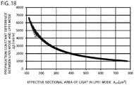
- Light having a wavelength of 1060 nm propagates in the core at least in the LP01 mode and the LP11 mode and the difference between the propagation constant of the light in the LP01 mode and the propagation constant of the light in the LP11 mode is set to 4000 rad/m or smaller. Therefore, compared with a single-mode fiber, it is possible to increase the effective sectional area of the light in the LP01 mode. Accordingly, it is possible to suppress the stimulated Raman scattering.
- the present inventors have found that deterioration in beam quality is suppressed when the difference between the propagation constant of the light in the LP01 mode and the propagation constant of the light in the LP11 mode propagating in the optical fiber is 1730 rad/m or larger.
- the present inventors have found that, even in an optical fiber in which light having a wavelength equal to or longer than 1000 nm and equal to or shorter than 1100 nm is capable of propagating in the core at least in the LP01 mode and the LP11 mode, deterioration in beam quality can also be suppressed when the optical fiber has the propagation constant difference. Accordingly, with the optical fiber of the present invention, it is possible to suppress deterioration in beam quality while suppressing the stimulated Raman scattering.
- light having at least a wavelength equal to or longer than 1060 nm and equal to or shorter than 1093 nm may be capable of propagating in the core at least in the LP01 mode and the LP11 mode.
- Light having at least a wavelength equal to or longer than 1030 nm and equal to or shorter than 1093 nm may be capable of propagating in the core at least in the LP01 mode and the LP11 mode.
- light having at least a wavelength longer than 1060 nm and equal to or shorter than 1080 nm may be capable of propagating in the core at least in the LP01 mode and the LP11 mode.
- the difference between the propagation constant of the light in the LP01 mode and the propagation constant of the light in the LP11 mode is smaller than 1850 rad/m.
- the optical fiber configured in this way is bent at a curvature radius equal to or smaller than 60 mm, it is possible to lose the light in the LP02 mode having a wavelength of 1060 nm. Therefore, in the laser device or the like, when the optical fiber is bent at the curvature radius equal to or smaller than 60 mm, even when a part of the light in the LP01 mode shifts to the light in the LP11 mode and further shifts to the light in the LP02 mode, since the light in the LP02 mode is lost, it is possible to suppress deterioration in beam quality of emitted light. Note that this tendency is the same in an optical fiber in which light having a wavelength equal to or longer than 1000 nm and equal to or shorter than 1100 nm is capable of propagating in a core at least in the LP01 mode and the LP11 mode.
- the optical fiber is configured in this way, in the laser device or the like, when the optical fiber is bent at the curvature radius equal to or smaller than 60 mm, most of the light in the LP02 mode having the wavelength of 1060 nm leaks from the core. The propagation of the light is suppressed in the core. Therefore, even when the light in the LP11 mode shifts to the light in the LP02 mode, when the light passes a portion bent at the curvature radius equal to or smaller than 60 mm of the optical fiber, since most of the light in the LP02 mode leaks from the core, it is possible to remove the light in the LP02 mode.
- the present invention is a laser device including the optical fiber described in any one of the above descriptions.
- FIG. 1 is a diagram illustrating a laser device according to an embodiment.
- a laser device 1 in this embodiment is a resonator-type fiber laser device.
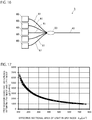
- the laser device 1 includes, as main components, an amplification optical fiber 10, a pumping light source 20, a first optical fiber 30, a first FBG 35 provided in the first optical fiber 30, a second optical fiber 40, a second FBG 45 provided in the second optical fiber 40, and an optical combiner 50.
- the amplification optical fiber 10 is a few-mode fiber.
- light having at least a wavelength of 1060 nm propagates in the core 11
- light in a high-order mode equal to or higher than a secondary LP mode propagates other than light in an LP01 mode, which is a basic mode.
- Examples of the light in the high-order mode include light in an LP11 mode, light in an LP21 mode, and light in an LP02 mode.
- a high refractive index portion where a refractive index is higher than a refractive index of portions other than the first FBG 35 of the core 31 and a low refractive index portion where a refractive index is the same as the refractive index of the portions other than the first FBG 35 of the core 31 are cyclically repeated along the longitudinal direction of the core 31.
- This repetition pattern of the high refractive index portion is formed by, for example, irradiating an ultraviolet ray on a part to be formed as the high refractive index portion.
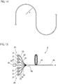
- a plurality of optical fibers are wound one round or more while changing a curvature radius from 30 mm to 50 mm, a shortest wavelength at which a bending loss of the light in the LP11 mode occurs is measured, a change in the shortest wavelength at which the bending loss of the light in the LP11 mode with respect to the inverse of the bending diameter occurs is linearly approximated, and a shortest wavelength at which a bending loss of the light in the LP11 mode at the curvature radius of 40 mm occurs is calculated again using the approximated straight line.
- the optical fiber is bent at the curvature radius equal to or smaller than 60 mm, even when a part of the light in the LP01 mode shifts to the light in the LP11 mode and further shifts to the light in the LP02 mode, it is possible to suppress deterioration in beam quality of emitted light by losing the light in the LP02 mode.
- the seed light source 70 includes, for example, a laser diode or a fiber laser and is configured to emit seed light having a wavelength of 1060 nm.
- the seed light source 70 is configured the same as the first optical fiber 30 in the first embodiment and connected to the first optical fiber 30 in which an FBG is not formed.
- the seed light emitted from the seed light source 70 propagates in a core of the first optical fiber 30.
- the light in the LP02 mode is remove. It is possible to suppress deterioration in beam quality of emitted light.
- FIG. 16 a third embodiment of the present invention is explained in detail with reference to FIG. 16 .
- components same as or equivalent to the components in the first embodiment are denoted by the same reference numerals and signs and explanation of the components is omitted except when the components are particularly explained.
- the second optical fiber 40 if a relative refractive index difference of the core with respect to a clad is 0.2% or less and a theoretical cutoff wavelength of light in an LP02 mode is 1760 nm or less, when the optical fiber is bent at a curvature radius equal to or smaller than 60 mm, it is possible to lose the light in the LP02 mode having the wavelength of 1060 nm.
- the theoretical cutoff wavelength in the LP02 mode when the light propagating in the optical fiber has, for example, the wavelength of 1000 nm, the theoretical cutoff wavelength in the LP02 mode may be 1327 nm to 1520 nm. However, the theoretical cutoff wavelength in the LP02 mode may be shorter than 1327 nm.
- the theoretical cutoff wavelength in the LP02 mode when the light propagating in the optical fiber has, for example, the wavelength of 1030 nm, the theoretical cutoff wavelength in the LP02 mode may be 1420 nm to 1640 nm. However, theoretical cutoff wavelength in the LP02 mode may be shorter than 1420 nm.
- the optical fiber and the laser device that can suppress deterioration in beam quality while suppressing stimulated Raman scattering are provided. Use in a laser device and the like for machining is expected.
Landscapes
- Physics & Mathematics (AREA)
- Optics & Photonics (AREA)
- General Physics & Mathematics (AREA)
- Electromagnetism (AREA)
- Engineering & Computer Science (AREA)
- Plasma & Fusion (AREA)
- Lasers (AREA)
- Optical Fibers, Optical Fiber Cores, And Optical Fiber Bundles (AREA)
- Optical Modulation, Optical Deflection, Nonlinear Optics, Optical Demodulation, Optical Logic Elements (AREA)
Applications Claiming Priority (2)
| Application Number | Priority Date | Filing Date | Title |
|---|---|---|---|
| JP2017254758 | 2017-12-28 | ||
| PCT/JP2018/048370 WO2019131970A1 (fr) | 2017-12-28 | 2018-12-27 | Fibre optique et dispositif laser |
Publications (2)
| Publication Number | Publication Date |
|---|---|
| EP3734336A1 true EP3734336A1 (fr) | 2020-11-04 |
| EP3734336A4 EP3734336A4 (fr) | 2021-08-25 |
Family
ID=67067653
Family Applications (1)
| Application Number | Title | Priority Date | Filing Date |
|---|---|---|---|
| EP18893405.3A Pending EP3734336A4 (fr) | 2017-12-28 | 2018-12-27 | Fibre optique et dispositif laser |
Country Status (5)
| Country | Link |
|---|---|
| US (1) | US11656402B2 (fr) |
| EP (1) | EP3734336A4 (fr) |
| JP (1) | JP6899924B2 (fr) |
| CN (1) | CN111566526B (fr) |
| WO (1) | WO2019131970A1 (fr) |
Families Citing this family (2)
| Publication number | Priority date | Publication date | Assignee | Title |
|---|---|---|---|---|
| JP7317220B2 (ja) * | 2020-04-08 | 2023-07-28 | 株式会社フジクラ | 光ファイバ及びファイバレーザ装置 |
| JP7457953B2 (ja) * | 2020-06-12 | 2024-03-29 | パナソニックIpマネジメント株式会社 | 発光装置及び発光システム |
Family Cites Families (17)
| Publication number | Priority date | Publication date | Assignee | Title |
|---|---|---|---|---|
| JPS56129223A (en) | 1980-03-17 | 1981-10-09 | Toray Ind Inc | Manufacture of highly viscous polyamide |
| US7103251B2 (en) * | 2002-12-31 | 2006-09-05 | Corning Incorporated | Dispersion flattened NZDSF fiber |
| US7336877B2 (en) | 2004-08-31 | 2008-02-26 | Corning Incorporated | Broadband optical fiber |
| US8797642B2 (en) * | 2007-07-20 | 2014-08-05 | Corning Incorporated | Large mode area optical fiber |
| CN101657943A (zh) * | 2007-08-28 | 2010-02-24 | 株式会社藤仓 | 稀土掺杂纤芯多包层光纤、光纤放大器和光纤激光器 |
| US8731358B2 (en) | 2008-01-17 | 2014-05-20 | Claude Pare | Multi-cladding fiber |
| US8693834B2 (en) | 2011-08-15 | 2014-04-08 | Corning Incorporated | Few mode optical fibers for mode division multiplexing |
| WO2013038794A1 (fr) * | 2011-09-12 | 2013-03-21 | 古河電気工業株式会社 | Fibre optique, laser à fibre optique, amplificateur à fibre optique et procédé de production de fibre optique |
| EP2756339A1 (fr) | 2011-09-16 | 2014-07-23 | Corning Incorporated | Fibres optiques multimodales pour un multiplexage en mode |
| JP5694266B2 (ja) * | 2012-10-02 | 2015-04-01 | 株式会社フジクラ | 光ファイバ及びそれを用いたファイバレーザ装置 |
| JP6511235B2 (ja) | 2014-09-01 | 2019-05-15 | 株式会社フジクラ | ファイバレーザ装置 |
| CN104793285B (zh) * | 2015-04-29 | 2018-01-02 | 武汉邮电科学研究院 | 低损耗少模光纤 |
| JP6744074B2 (ja) | 2015-07-16 | 2020-08-19 | 株式会社フジクラ | 光ファイバグレーティング用光ファイバおよびファイバレーザ装置 |
| WO2018003184A1 (fr) * | 2016-06-30 | 2018-01-04 | 株式会社フジクラ | Fibre optique pour amplification et dispositif laser |
| JP6268232B2 (ja) * | 2016-07-04 | 2018-01-24 | 株式会社フジクラ | 光ファイバ、及び、レーザ装置 |
| WO2019131971A1 (fr) * | 2017-12-28 | 2019-07-04 | 株式会社フジクラ | Fibre optique et dispositif laser |
| US10983267B2 (en) * | 2018-03-08 | 2021-04-20 | Corning Incorporated | Quasi-single-mode optical fiber |
-
2018
- 2018-12-27 EP EP18893405.3A patent/EP3734336A4/fr active Pending
- 2018-12-27 CN CN201880083874.4A patent/CN111566526B/zh active Active
- 2018-12-27 WO PCT/JP2018/048370 patent/WO2019131970A1/fr not_active Ceased
- 2018-12-27 US US16/958,332 patent/US11656402B2/en active Active
- 2018-12-27 JP JP2019562487A patent/JP6899924B2/ja active Active
Also Published As
| Publication number | Publication date |
|---|---|
| CN111566526A (zh) | 2020-08-21 |
| CN111566526B (zh) | 2022-06-24 |
| JP6899924B2 (ja) | 2021-07-07 |
| JPWO2019131970A1 (ja) | 2020-07-27 |
| EP3734336A4 (fr) | 2021-08-25 |
| WO2019131970A1 (fr) | 2019-07-04 |
| US11656402B2 (en) | 2023-05-23 |
| US20210066879A1 (en) | 2021-03-04 |
Similar Documents
| Publication | Publication Date | Title |
|---|---|---|
| EP3462553B1 (fr) | Fibre optique et dispositif laser | |
| JP6306625B2 (ja) | シングルモード動作を維持したままクラッド吸収を増加させたダブルクラッドの利得をもたらすファイバ | |
| US8498044B2 (en) | Amplification optical fiber, and optical fiber amplifier and resonator using the same | |
| US11114811B2 (en) | Multimode fiber, optical amplifier, and fiber laser | |
| JP5982307B2 (ja) | フォトニックバンドギャップファイバ、及び、それを用いたファイバレーザ装置 | |
| WO2018003184A1 (fr) | Fibre optique pour amplification et dispositif laser | |
| WO2016035414A1 (fr) | Dispositif de laser à fibre | |
| US11656402B2 (en) | Optical fiber and laser device | |
| JP7124210B2 (ja) | 活性元素添加光ファイバ、共振器、及び、ファイバレーザ装置 | |
| JP6744074B2 (ja) | 光ファイバグレーティング用光ファイバおよびファイバレーザ装置 | |
| US20210057866A1 (en) | Optical fiber and laser device | |
| JP7268245B2 (ja) | 活性元素添加光ファイバ、活性元素添加光ファイバ用母材、共振器、及び、ファイバレーザ装置 | |
| JP6499126B2 (ja) | 光コンバイナ、光増幅器、及び、レーザ装置 | |
| WO2020203930A1 (fr) | Fibre optique à élément actif, résonateur et dispositif laser à fibre |
Legal Events
| Date | Code | Title | Description |
|---|---|---|---|
| STAA | Information on the status of an ep patent application or granted ep patent |
Free format text: STATUS: THE INTERNATIONAL PUBLICATION HAS BEEN MADE |
|
| PUAI | Public reference made under article 153(3) epc to a published international application that has entered the european phase |
Free format text: ORIGINAL CODE: 0009012 |
|
| STAA | Information on the status of an ep patent application or granted ep patent |
Free format text: STATUS: REQUEST FOR EXAMINATION WAS MADE |
|
| 17P | Request for examination filed |
Effective date: 20200723 |
|
| AK | Designated contracting states |
Kind code of ref document: A1 Designated state(s): AL AT BE BG CH CY CZ DE DK EE ES FI FR GB GR HR HU IE IS IT LI LT LU LV MC MK MT NL NO PL PT RO RS SE SI SK SM TR |
|
| AX | Request for extension of the european patent |
Extension state: BA ME |
|
| DAV | Request for validation of the european patent (deleted) | ||
| DAX | Request for extension of the european patent (deleted) | ||
| A4 | Supplementary search report drawn up and despatched |
Effective date: 20210727 |
|
| RIC1 | Information provided on ipc code assigned before grant |
Ipc: G02B 6/036 20060101AFI20210721BHEP Ipc: G02B 6/02 20060101ALI20210721BHEP Ipc: H01S 3/067 20060101ALI20210721BHEP |
|
| STAA | Information on the status of an ep patent application or granted ep patent |
Free format text: STATUS: EXAMINATION IS IN PROGRESS |
|
| 17Q | First examination report despatched |
Effective date: 20230612 |