EP3735507B1 - Bohranordnung und zugehöriges bohrverfahren - Google Patents
Bohranordnung und zugehöriges bohrverfahren Download PDFInfo
- Publication number
- EP3735507B1 EP3735507B1 EP19700057.3A EP19700057A EP3735507B1 EP 3735507 B1 EP3735507 B1 EP 3735507B1 EP 19700057 A EP19700057 A EP 19700057A EP 3735507 B1 EP3735507 B1 EP 3735507B1
- Authority
- EP
- European Patent Office
- Prior art keywords
- support
- nozzle
- boring
- head
- jet
- Prior art date
- Legal status (The legal status is an assumption and is not a legal conclusion. Google has not performed a legal analysis and makes no representation as to the accuracy of the status listed.)
- Active
Links
Images

Classifications
-
- E—FIXED CONSTRUCTIONS
- E21—EARTH OR ROCK DRILLING; MINING
- E21B—EARTH OR ROCK DRILLING; OBTAINING OIL, GAS, WATER, SOLUBLE OR MELTABLE MATERIALS OR A SLURRY OF MINERALS FROM WELLS
- E21B7/00—Special methods or apparatus for drilling
- E21B7/18—Drilling by liquid or gas jets, with or without entrained pellets
-
- E—FIXED CONSTRUCTIONS
- E21—EARTH OR ROCK DRILLING; MINING
- E21B—EARTH OR ROCK DRILLING; OBTAINING OIL, GAS, WATER, SOLUBLE OR MELTABLE MATERIALS OR A SLURRY OF MINERALS FROM WELLS
- E21B10/00—Drill bits
- E21B10/60—Drill bits characterised by conduits or nozzles for drilling fluids
-
- E—FIXED CONSTRUCTIONS
- E21—EARTH OR ROCK DRILLING; MINING
- E21B—EARTH OR ROCK DRILLING; OBTAINING OIL, GAS, WATER, SOLUBLE OR MELTABLE MATERIALS OR A SLURRY OF MINERALS FROM WELLS
- E21B7/00—Special methods or apparatus for drilling
- E21B7/16—Applying separate balls or pellets by the pressure of the drill, so-called shot-drilling
-
- E—FIXED CONSTRUCTIONS
- E21—EARTH OR ROCK DRILLING; MINING
- E21B—EARTH OR ROCK DRILLING; OBTAINING OIL, GAS, WATER, SOLUBLE OR MELTABLE MATERIALS OR A SLURRY OF MINERALS FROM WELLS
- E21B7/00—Special methods or apparatus for drilling
- E21B7/24—Drilling using vibrating or oscillating means, e.g. out-of-balance masses
-
- E—FIXED CONSTRUCTIONS
- E21—EARTH OR ROCK DRILLING; MINING
- E21B—EARTH OR ROCK DRILLING; OBTAINING OIL, GAS, WATER, SOLUBLE OR MELTABLE MATERIALS OR A SLURRY OF MINERALS FROM WELLS
- E21B21/00—Methods or apparatus for flushing boreholes, e.g. by use of exhaust air from motor
- E21B21/06—Arrangements for treating drilling fluids outside the borehole
- E21B21/063—Arrangements for treating drilling fluids outside the borehole by separating components
- E21B21/065—Separating solids from drilling fluids
Definitions
- a drilling assembly extending along a central axis is provided.
- the invention also relates to a drilling method.
- the invention relates to drilling in a civil engineering structure, in particular during the dismantling of nuclear power plants.
- the system includes a drill head configured to deliver a high pressure water jet and another drill head configured to deliver an abrasive jet.
- the aim of the invention is then to propose a drilling assembly making it possible to simplify its handling.
- the invention relates to a drilling assembly according to claim 1.
- Handling of the drilling assembly according to the invention is simpler. Indeed, drilling using the drilling assembly according to the invention does not require the alternating introduction of several drilling heads, as is the case for drilling systems of the state of the art, which leads to wasted time and drilling inaccuracies.
- the drilling assembly comprises one or more of the characteristics of claims 2 to 8.
- the invention also relates to a drilling method using a drilling assembly as described above according to claim 9.
- the drilling method is according to claim 10.
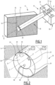
- a drilling assembly 10 is shown on the figure 1 .
- the drilling assembly 10 is configured to drill a wall 12, in particular a wall 12 comprising mineral and metallic elements.
- the wall 12 is made of reinforced concrete composed of concrete 14 and metallic elements 16.
- the metallic elements 16 are, for example, iron or steel bars.
- the drilling assembly 10 extends along a main axis A-A'.
- the drilling assembly 10 comprises a drilling head 18 comprising at least one first nozzle 20 and at least one second nozzle 22, the or each second nozzle 22 being different from the or each first nozzle 20.
- the drilling assembly 10 comprises in the example illustrated in the figures, a single first nozzle 20 and a single second nozzle 22.
- the drilling head 18 is cylindrical in shape.
- the drilling head 18 has a central head axis BB' extending along the main axis A-A'.
- the drilling head 18 has a diameter greater than 200 mm.
- the diameter has no upper limit.
- the drilling head 18 has a diameter in particular between 200 mm and 1000 mm, for example 280 mm.
- the drilling head 18 has a front face 24, the front face 24 being configured to be arranged facing the area of the wall 12 to be drilled.
- the front face 24 is substantially orthogonal to the central axis of the head B-B'.
- the or each first nozzle 20 is configured to provide a jet of fluid, in particular a jet of water without abrasive.
- abrasive we mean a very hard material used to wear away other softer materials.
- the abrasive material has a hardness above 6 mohs.
- An abrasive material is also characterized by its particle size, advantageously between 30 and 80 mesh.
- the or each second nozzle 22 is configured to provide a jet of fluid, in particular a jet comprising at least one abrasive material.
- the abrasive material is, for example, composed of garnet or almond.
- the fluid is water to which the abrasive material is added.
- the drilling assembly 10 further comprises a first supply device 26 and a second supply device 28.
- the first supply device 26 is configured to supply the abrasive-free water jet to the at least one first nozzle 20.
- the first supply device 26 is configured to supply the water jet at very high pressure in order to allow drilling by demolition by bursting of the concrete 14.
- the very high pressure of the water jet is between 2000 bar and 3000 bar.
- the associated flow rate of the water jet is between 10 l.min -1 and 20 l.min -1 .
- the drilling assembly 10 advantageously comprises at least a third nozzle, not shown in the figures.
- the first supply device 26 is further configured to supply a jet of water without abrasive at low pressure to the at least one third nozzle in order to allow the evacuation of rubble from the area of the wall 12 to be drilled.
- the low pressure of the water jet is between 2 bar and 10 bar.
- the associated flow rate of the water jet is then between 20 l.min -1 and 100 l.min -1 .
- the first supply device 26 advantageously comprises a reservoir comprising water, a pump and a conduit from the reservoir to the or each first nozzle 20, not shown.
- the second supply device 28 is configured to supply the jet comprising at least one abrasive material to the at least one second nozzle 22.
- the pressure of the abrasive jet is between 2000 and 3000 bars.
- the associated flow rate of the abrasive jet is then between 200 and 500 g.min -1 .
- the second supply device 28 advantageously comprises a reservoir comprising an abrasive material, a pump and a conduit from the reservoir to the or each second nozzle 22, not shown.
- the drilling assembly 10 further comprises a frame 30 and a first drive 32.
- the frame 30 is a support located away from the wall 12.
- the frame 30 is fixed relative to the wall 12.
- the first drive 32 is configured to rotate the drilling head 18 relative to the frame 30 around the central head axis B-B'.
- the amplitude of the rotation permitted by the first drive 26 is 360°.
- the first drive 32 is of any type suitable for enabling said rotation.
- the first drive 32 is a gear motor.
- the drilling assembly 10 also includes a body 34, a first support 36 and a second drive 38.
- the body 34 is cylindrical in shape, having the head axis B-B' as the central axis and of the same diameter as the drilling head 18.
- the front face of the body 34 is parallel and substantially at the same level as the front face 24 of the drilling head 18.
- the first support 36 is cylindrical in shape, having a central axis of the first support C-C' different from the central axis of the head B-B'.
- the central axis of first support C-C' is for example substantially parallel to the central axis of head B-B'.
- the central axis of the first support C-C' makes a non-zero angle, in particular between 0° and 45°, with the central axis of the head B-B'.
- the or each second nozzle 22 is configured to provide an orientable jet making an angle between 0° and 80° relative to an axis FF' passing through said second nozzle 22 and parallel to the axis of first support C-C'.
- the first support 36 is inserted into the body 34.
- the first support 36 is linked in rotation to the body 34 around the central axis of the first support C-C'.
- the first support 36 opens onto the front face 24.
- the front face of the first support 36 is for example parallel and substantially at the same level as the front face 24 of the drilling head 18.
- the or each second nozzle 22 is arranged on the first support 36 and, in particular, on the front face of the first support 36.
- the second drive 38 is configured to rotate the first support 36 relative to the body 34 around the central axis of the first support C-C'.
- the amplitude of the rotation permitted by the second drive 28 is 180°.
- the second drive 38 is of any type suitable to allow said rotation.
- the second drive 38 is a gear motor.
- the nozzles 20, 22 are able to follow any desired trajectory on the front face 24.
- the drilling assembly 10 further comprises a second support 40 and a third drive 42.
- the second support 40 is cylindrical in shape, having a central axis of the second support D-D' different from the central axis of the first support C-C'.
- the central axis of second support D-D' is advantageously substantially parallel to the central axis of first support C-C'.
- the central axis of the second support D-D' makes a non-zero angle with the axis of the first support C-C'.
- the or each first nozzle 20 is configured to provide a jet making an angle between 0° and 45° relative to an axis EE' passing through said first nozzle 20 and parallel to the central axis of second support D-D' .
- the second support 40 is inserted into the first support 36.
- the second support 40 is linked in rotation to the first support 36 around the central axis of the second support D-D'.
- the second support 40 opens onto the front face 24.
- the front face of the second support 40 is parallel and substantially at the same level as the front face 24 of the drilling head 18.
- the or each first nozzle 20 is advantageously arranged on the second support 40.
- the or each first nozzle 20 is located on the front face of the second support 40.
- the third drive 42 is configured to rotate the second support 40 relative to the first support 36 around the central axis of the second support D-D'.
- the amplitude of the rotation permitted by the third drive 42 is 360°.
- the third drive 42 is configured to allow continuous rotation of the second support 40, in particular at a rotation speed of between 100 and 600 rpm -1 , for example 500 rpm -1 .
- the third drive 42 is of any type suitable to allow said rotation.
- the third drive 42 is a gear motor.
- the third drive 42 is configured to allow the rotation of the second support 40 by means of the flow of water circulating through the or each first nozzle 20.
- the drilling assembly 10 comprises a suction mouth 44.
- the suction mouth 44 is provided in the body 34 and the opening of the suction mouth 44 opens onto the front face 24.
- the suction mouth 44 extends along the central axis of head B- B'.
- the suction mouth 44 is configured to suck through the opening the rubble resulting from the drilling of the wall 12 as well as the fluids injected by the nozzles 20, 22 and to transport the rubble and the fluids from the front face 24 towards the outside of wall 12.
- the suction mouth 44 is advantageously connected to a pump, not shown, configured to create a vacuum causing the suction and transport of rubble and fluids.
- the drilling assembly 10 advantageously comprises a lighting device 46 and a camera 48.
- the lighting device 46 is carried by the first support 36, in particular on the front face of the first support 36.
- the lighting device 46 is configured to illuminate the area of the wall 12 to be drilled.
- the lighting device 46 is advantageously composed of a plurality of lamps arranged regularly along a circle around the camera 48.
- the camera 48 is carried by the first support 36, in particular on the front face of the first support 36.
- the camera 48 is configured to record and transmit to a screen, not shown and located outside the wall 12, photographs or videos of the area of wall 12 to be drilled.
- the camera 48 is configured to instantly transmit the images taken to the screen in order to allow better control of the drilling.
- the lighting device 46 and the camera 48 are configured to go from a hidden configuration in which the lighting device 46 and the camera 48 are protected during drilling, to an active configuration in which the lighting device 46 and the camera 48 are able to illuminate and film the area of the wall 12 to be drilled.
- the drilling assembly 10 comprises at least a fourth nozzle, not shown in the figures, configured to provide a jet of compressed air on the lighting device 46 and the camera 48 in order to clean them and/or protect them from dripping during viewing steps after drilling steps.
- the drilling assembly 10 also includes a fourth drive 50.
- the fourth drive 50 is configured to drive the drilling head 18 in translation along the central axis of the head B-B' relative to the chassis 30 and thus makes it possible to advance the drilling of the wall 12 as the reinforced concrete is drilled.
- the fourth drive 50 is of any type suitable for enabling said translation.
- the fourth drive 50 is a screw-nut system or a rack.
- the drilling assembly 10 is away from the wall 12.
- the front face 24 of the drilling head 18 is placed facing the wall 12 by means of the fourth drive 50 which moves the drilling head 18 in translation along the central axis of the head B-B' relative to the chassis 30.
- the first drive 32 and the second drive 38 place the drilling head 18 and the first support 36 in the desired position facing the area of the wall 12 to be drilled.
- the drilling process then comprises a step of first supply by the first supply device 26 of a jet of water without abrasive at very high pressure to the or each first nozzle 20.
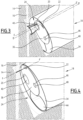
- the concrete body 14 is then demolished by the abrasive-free water jet at very high pressure, as visible on the Figure 3 .
- a thickness of concrete 14 of between 40 mm and 60 mm is demolished during the first supply stage.
- the third drive 42 rotates the or each first nozzle 20 around the central axis of second support DD' relative to the first support 36.
- the abrasive-free water jet then describes a cone around the axis central of second support D-D', as shown on the Figure 3 thus allowing easier demolition of concrete thickness 14.
- the or each first nozzle 20 describes the desired trajectory and makes it possible to remove a layer of the wall 12 of concrete 14 following the diameter of the drilling.
- the fourth drive 50 drives the drilling head 18 in translation in stages as the concrete zone 14 of the wall 12 is demolished.
- the lighting device 46 and the camera 48 switch from the hidden configuration to the active configuration.
- the lighting device 46 illuminates the area to be drilled and the camera 48 films and transmits the images of the area of the wall 12 to be drilled in order to control the drilling and identify any metal elements 16 that may have been removed, in particular steel or iron bars.
- the step of first supplying the abrasive-free water jet at very high pressure stops.
- the first supply device 26 supplies a jet of water without abrasive at low pressure to the or each third nozzle in order to remove the rubble present facing the front face 24.
- the mouth suction 44 sucks up the water injected by the jet and the rubble and transports them outside the wall 12.
- the lighting device 46 and the camera 48 make it possible to identify the position and shape of the metal element 16.
- the first drive 32 and the second drive 38 place the drilling head 18 and the first support 36 in the desired position facing the metal element 16 to be destroyed.
- the drilling method then comprises a step of second supply by the second supply device 28 of a jet comprising at least one abrasive material to the or each second nozzle 22.
- the metal element 16 is then cut by the abrasive jet, as visible on the figures 4 And 5 .
- the or each second nozzle 22 directs the abrasive jet according to the shape and orientation of the metal element 16.
- the or each second nozzle 22 makes it possible to cut a metal element 16 oriented substantially in the same direction as the front face 24, as visible on the figure 4 .
- the or each second nozzle 22 also makes it possible to cut a metal element 16 oriented substantially along the central axis of the head B-B', as visible on the figure 5 , with a different orientation of the abrasive jet.
- the or each second nozzle 22 describes the desired trajectory and makes it possible to precisely destroy the metal element 16.
- the first supply device 26 supplies a jet of water without abrasive at low pressure to the or each third nozzle in order to remove the rubble present facing the front face 24.
- the mouth d The suction 44 sucks up the water injected by the jet and the pieces of iron and transports them outside the wall 12.
- the suction is carried out during the demolition stages of the wall 12, in order to remove the concrete rubble 14 and the metal elements 16 cut continuously.
- first supply and second supply are used as simple terminology but do not imply any temporal correlation relationship between the steps of the drilling process.
- the first supply can thus be made before, during or after the second supply.
- the drilling process subsequently alternately comprises first supply steps to demolish the concrete areas 14 of the wall 12 and second supply steps to destroy the metal elements 16 present in wall 12.
- the drilling method therefore allows drilling in a wall 12 of reinforced concrete not requiring the alternating introduction of several drilling heads and thus allowing easier handling of the drilling assembly 10.
- the absence of round trips is favorable for reducing the dispersion of rubble and effluent, which constitutes a sensitive point when working in contaminated environment.
- the different drives 32, 38, 42, 50 and the orientation of the jets at the outlet of the nozzles 20, 22 make it possible to split the different elements 14 of the wall 12 into residual rubble small enough to be extracted and transported by the suction mouth 44 by means of the flow of water injected by the or each third nozzle.
- the hydrodemolition permitted by the or each first nozzle 20 and the first supply device 26 makes it possible to split the concrete 14 into pieces whose size is given by the mineral elements, such as pebbles, entering into the composition of the concrete 14
- the precise cutting of the metal elements 16 by means of the controlled trajectory of the or each second nozzle 22 makes it possible to split the metal elements 16, such as steel or iron bars, into small sections which can be easily transported by the suction mouth. 44.
- the drilling assembly 10 also makes it possible to carry out inclined drilling without damaging the equipment located near the wall 12.
- Inclined drilling means drilling carried out in a direction making a non-zero angle with the axis normal to the exit face, in particular an angle greater than 20° as visible according to the figure 1 .
- Inclined drilling is particularly advantageously carried out in a direction going from top to bottom.
- the metal elements 16 are usually found in a civil engineering structure at least 50 mm inside the wall 12.
- the alternating use of the nozzles 20, 22 and the abrasive cuts can be made in a targeted manner on the metal sections, the end of the drilling can emerge outside the wall 12 without using the abrasive cutting jet.
- the sole use of the jet without abrasive allows you not to cut any metal elements beyond drilling and in particular to pierce a possible metal wall to be preserved.
- the alternating use of the two supply devices 22, 24 makes it possible to optimize the quantity of abrasives used, which allows a reduction in costs as well as the ecological impact of drilling.
- the drilling assembly 10 makes it possible to reduce the reaction forces of the jets, typically less than 10 daN, which lightens the structure and the necessary weight of the drilling assembly 10, unlike drilling carried out with a jackhammer for example which leads to cracks in the structure.
- the drilling assembly 10 is in particular advantageously used for the dismantling of damaged nuclear power plants such as the Fukushima power plant for example.
- the drilling assembly 10 is also used to make openings in civil engineering structures when it is important to preserve the reinforcement at the edge of the opening in order to then be able to re-mesh the structure according to a new need.
Landscapes
- Engineering & Computer Science (AREA)
- Geology (AREA)
- Life Sciences & Earth Sciences (AREA)
- Mining & Mineral Resources (AREA)
- Environmental & Geological Engineering (AREA)
- Fluid Mechanics (AREA)
- Physics & Mathematics (AREA)
- General Life Sciences & Earth Sciences (AREA)
- Geochemistry & Mineralogy (AREA)
- Mechanical Engineering (AREA)
- Perforating, Stamping-Out Or Severing By Means Other Than Cutting (AREA)
- Processing Of Stones Or Stones Resemblance Materials (AREA)
- Earth Drilling (AREA)
- Working Measures On Existing Buildindgs (AREA)
Claims (10)
- Bohranordnung (10), die sich entlang einer Hauptachse (A-A') erstreckt und Folgendes umfasst:- einen Bohrkopf (18), umfassend:+ mindestens eine erste Düse (20);+ mindestens eine zweite Düse (22), wobei die oder jede zweite Düse (22) von der oder jeder ersten Düse (20) verschieden ist;- eine erste Zufuhrvorrichtung (26), die konfiguriert ist, um der mindestens einen ersten Düse (20) einen Wasserstrahl ohne Schleifmittel mit einem Druck zwischen 2000 bar und 4000 bar zuzuführen;- eine zweite Zufuhrvorrichtung (28), die konfiguriert ist, um der mindestens einen zweiten Düse (22) einen Strahl mit mindestens einem abrasiven Material bei einem Druck zwischen 2000 bar und 6000 bar zuzuführen,
wobei der Bohrkopf (18) zylindrisch geformt ist und eine Kopfmittelachse (B-B') aufweist, die sich entlang der Hauptachse (A-A') erstreckt, die Bohranordnung (10) umfassend- einen Rahmen (30),- einen ersten Drehantrieb (32) des Bohrkopfs (18) in Bezug auf den Rahmen (30) um die Kopfmittelachse (B-B'),- einen Körper (34);- eine erste Halterung (36) in zylindrischer Form, die eine Mittelachse der ersten Halterung (C-C') aufweist, die sich von der Mittelachse des Kopfs (B-B') unterscheidet,- einen zweiten Drehantrieb (38) der ersten Halterung (36) in Bezug auf den Körper (34) um die Mittelachse der ersten Halterung (C-C'), wobei die mindestens eine zweite Düse (22) auf der ersten Halterung (36) angeordnet ist und die erste Halterung (36) um die Mittelachse der ersten Halterung (C-C') drehbar mit dem Körper (34) verbunden ist;
wobei:* die mindestens eine erste Düse (20) auf der ersten Halterung (36) angeordnet ist; oder* die Bohranordnung (10) eine zweite Halterung (40) mit zylindrischer Form umfasst, die eine von der Mittelachse der ersten Halterung (C-C') verschiedene Mittelachse der zweiten Halterung (D-D') aufweist, wobei die zweite Halterung (40) in die erste Halterung (36) eingefügt ist und die mindestens eine erste Düse (20) an der zweiten Halterung (40) angeordnet ist. - Bohranordnung (10) nach Anspruch 1, wobei der Bohrkopf (18) einen Durchmesser zwischen 200 mm und 1000 mm aufweist.
- Bohranordnung (10) nach einem der vorherigen Ansprüche, umfassend - einen dritten Antrieb (42) zum Drehen der zweiten Halterung (40) in Bezug auf die erste Halterung (36) um die Mittelachse der zweiten Halterung (D-D'), wobei die zweite Halterung (40) mit der ersten Halterung (36) um die Mittelachse der zweiten Halterung (D-D') drehbar verbunden ist.
- Bohranordnung (10) nach einem der vorherigen Ansprüche, wobei die mindestens eine zweite Düse (22) konfiguriert ist, um einen steuerbaren Strahl zuzuführen, der einen Winkel zwischen 0° und 45° in Bezug auf eine Achse (F-F') bildet, die durch die zweite Düse (22) verläuft und parallel zu der Hauptachse (A-A') ist.
- Bohranordnung (10) nach einem der vorherigen Ansprüche, umfassend eine Saugöffnung (44) für Schutt, die vorzugsweise in dem Körper (34) ausgebildet ist und sich entlang der Hauptachse (A-A') erstreckt.
- Bohranordnung (10) nach einem der vorherigen Ansprüche, wobei der Bohrkopf (18) eine Beleuchtungseinrichtung (46) und eine Kamera (48) umfasst, die vorzugsweise von der ersten Halterung (36) getragen werden.
- Bohranordnung (10) nach einem der vorherigen Ansprüche in Kombination mit Anspruch 3, umfassend einen vierten Antrieb (50) für den Bohrkopf zur Translation entlang der Hauptachse (A-A') in Bezug auf den Rahmen (30).
- Bohranordnung (10) nach einem der vorherigen Ansprüche, wobei der Bohrkopf (18) eine Vorderseite (24) aufweist, die im Wesentlichen orthogonal zu der Hauptachse (A-A') ist, wobei die erste Düse (20) und die zweite Düse (22) in die Vorderseite (24) münden.
- Bohrverfahren mittels einer Bohranordnung (10) nach einem der Ansprüche 1 bis 8, umfassend die folgenden Schritte:- erste Zufuhr, durch die erste Zufuhrvorrichtung (26), eines Wasserstrahls ohne Schleifmittel mit einem Druck zwischen 2000 bar und 4000 bar zu der mindestens einen ersten Düse (20);- zweite Zufuhr, durch die zweite Zufuhrvorrichtung (28), eines Strahls umfassend mindestens ein Schleifmaterial bei einem Druck zwischen 2000 bar und 6000 bar an die mindestens eine zweite Düse (22);
wobei die erste Zufuhr vor, während und/oder nach der zweiten Zufuhr erfolgt. - Bohrverfahren nach Anspruch 9, umfassend die folgenden Schritte:- Abreißen eines Betonkörpers (14) durch den Wasserstrahl ohne Schleifmittel, der bei der ersten Zufuhr zugeführt wird,- Schneiden eines Metallelements (16) durch den Strahl, umfassend mindestens ein Schleifmaterial, das bei der zweiten Zufuhr zugeführt wird.
Applications Claiming Priority (2)
| Application Number | Priority Date | Filing Date | Title |
|---|---|---|---|
| FR1850103A FR3076568B1 (fr) | 2018-01-05 | 2018-01-05 | Ensemble de forage et procede de forage associe |
| PCT/EP2019/050139 WO2019134956A1 (fr) | 2018-01-05 | 2019-01-04 | Ensemble de forage et procédé de forage associé |
Publications (2)
| Publication Number | Publication Date |
|---|---|
| EP3735507A1 EP3735507A1 (de) | 2020-11-11 |
| EP3735507B1 true EP3735507B1 (de) | 2024-02-14 |
Family
ID=62167454
Family Applications (1)
| Application Number | Title | Priority Date | Filing Date |
|---|---|---|---|
| EP19700057.3A Active EP3735507B1 (de) | 2018-01-05 | 2019-01-04 | Bohranordnung und zugehöriges bohrverfahren |
Country Status (6)
| Country | Link |
|---|---|
| US (1) | US11384602B2 (de) |
| EP (1) | EP3735507B1 (de) |
| JP (1) | JP7266606B2 (de) |
| ES (1) | ES2977186T3 (de) |
| FR (1) | FR3076568B1 (de) |
| WO (1) | WO2019134956A1 (de) |
Families Citing this family (1)
| Publication number | Priority date | Publication date | Assignee | Title |
|---|---|---|---|---|
| CN113183037B (zh) * | 2021-04-02 | 2022-09-02 | 山东大学 | 一种磨料水射流全断面切割式刀盘及应用装置 |
Citations (1)
| Publication number | Priority date | Publication date | Assignee | Title |
|---|---|---|---|---|
| US2868509A (en) * | 1956-06-07 | 1959-01-13 | Jersey Prod Res Co | Pellet impact drilling apparatus |
Family Cites Families (14)
| Publication number | Priority date | Publication date | Assignee | Title |
|---|---|---|---|---|
| US2698736A (en) * | 1952-01-29 | 1955-01-04 | Standard Oil Dev Co | Combination pellet impact drill and annulus cutting drill |
| US3897836A (en) * | 1973-10-18 | 1975-08-05 | Exotech | Apparatus for boring through earth formations |
| JPS5645334A (en) * | 1979-09-22 | 1981-04-25 | Tsukahara Koichi | Processing device with extra-high pressure water |
| JPS6121271A (ja) * | 1984-07-11 | 1986-01-29 | 石川島播磨重工業株式会社 | コンクリ−ト構造物の破壊方法 |
| US4708214A (en) * | 1985-02-06 | 1987-11-24 | The United States Of America As Represented By The Secretary Of The Interior | Rotatable end deflector for abrasive water jet drill |
| BE905265A (nl) * | 1986-08-13 | 1986-12-01 | Smet Nik | Werkwijze en inrichting voor het maken van een gat in de grond. |
| JPS642899A (en) * | 1987-06-26 | 1989-01-06 | Kenzo Hoshino | Cutting method |
| BE1004617A3 (nl) * | 1990-10-15 | 1992-12-22 | Smet Marc Jozef Maria | Boorkop. |
| JPH054199A (ja) * | 1991-06-25 | 1993-01-14 | Kiyoyuki Horii | 切削・切断方法とその装置 |
| JPH09256767A (ja) * | 1996-03-19 | 1997-09-30 | Mitsui Eng & Shipbuild Co Ltd | 高圧水噴射式削孔方法及びその装置 |
| US8864240B2 (en) | 2010-09-20 | 2014-10-21 | Ash Equipment Company, Inc. | Vertical or horizontal robot for hydrodemolition of concrete |
| JP2014015731A (ja) * | 2012-07-06 | 2014-01-30 | Tokyo Metro Co Ltd | 高圧水削孔ノズルヘッド |
| EP3487187B1 (de) | 2016-07-14 | 2022-07-27 | Sony Group Corporation | Lautsprechervorrichtung |
| DE102016125916A1 (de) * | 2016-12-30 | 2018-07-05 | Hochschule Bochum | Bohrvorrichtung |
-
2018
- 2018-01-05 FR FR1850103A patent/FR3076568B1/fr not_active Expired - Fee Related
-
2019
- 2019-01-04 WO PCT/EP2019/050139 patent/WO2019134956A1/fr not_active Ceased
- 2019-01-04 EP EP19700057.3A patent/EP3735507B1/de active Active
- 2019-01-04 ES ES19700057T patent/ES2977186T3/es active Active
- 2019-01-04 JP JP2020537179A patent/JP7266606B2/ja active Active
- 2019-01-04 US US16/960,038 patent/US11384602B2/en active Active
Patent Citations (1)
| Publication number | Priority date | Publication date | Assignee | Title |
|---|---|---|---|---|
| US2868509A (en) * | 1956-06-07 | 1959-01-13 | Jersey Prod Res Co | Pellet impact drilling apparatus |
Also Published As
| Publication number | Publication date |
|---|---|
| FR3076568A1 (fr) | 2019-07-12 |
| US11384602B2 (en) | 2022-07-12 |
| EP3735507A1 (de) | 2020-11-11 |
| FR3076568B1 (fr) | 2020-11-27 |
| WO2019134956A1 (fr) | 2019-07-11 |
| JP2021510187A (ja) | 2021-04-15 |
| ES2977186T3 (es) | 2024-08-20 |
| JP7266606B2 (ja) | 2023-04-28 |
| US20200347679A1 (en) | 2020-11-05 |
Similar Documents
| Publication | Publication Date | Title |
|---|---|---|
| BE1012751A5 (fr) | Trepan a lames rotatif dirigeable a agressivite longitudinale variable de la zone de front de taille. | |
| BE1013011A5 (fr) | Element de coupe, trepan de forage, systeme et procede de forage de formations plastiques molles. | |
| BE1003792A3 (fr) | Trepan de forage combine. | |
| EP0114016A1 (de) | Bohrmeissel für kombiniertes Dreh- und Strahlbohren | |
| BE1014353A5 (fr) | Element coupant et trepan tournant utilisant cet element. | |
| BE1012649A5 (fr) | Element de coupe superabrasif avec chanfrein plan supporte par un contrefort et trepans de forage equipes d'un tel element. | |
| EP1627703B1 (de) | Tiefbohrkopf und Tiefbohrverfahren zur Bohrung eines Werkstücks | |
| FR2607865A1 (fr) | Procede et appareil de perforation de tubage pour puits de petrole | |
| EP0169110B1 (de) | Bohrwerkzeuge mit Wasserdurchlässen zur Erzielung einer hohen Reinigungswirkung der Angriffsfläche | |
| FR2713698A1 (fr) | Trépan de forage à pièces rapportées calibrées coupantes libres avec angles de sécurité . | |
| FR2915232A1 (fr) | Trepan pour le forage d'un puits et procede de forage associe. | |
| BE1020012A3 (fr) | Trepan rotatif bi-centre et procede pour l'approfondissement d'un puits preexistant. | |
| EP3735507B1 (de) | Bohranordnung und zugehöriges bohrverfahren | |
| BE1013515A5 (fr) | Agencement de trepan tricone. | |
| EP2156907A1 (de) | Einrichtung zur Bodensanierung | |
| CA2518879A1 (fr) | Methode et systeme de forage avec circulation inverse | |
| FR2699852A1 (fr) | Procédé et dispositif d'usinage à jet de fluide haute pression asservi. | |
| CN113898286A (zh) | 一种单动钻具及复合式取心钻具 | |
| EP0017518B1 (de) | Drehbohrmaschine und Bohrverfahren mittels dieser Maschine | |
| CA2641395C (fr) | Systeme de forage autonome d'un trou de drainage | |
| FR2982633A1 (fr) | Composant pour le forage et l'exploitation des puits d'hydrocarbures | |
| FR2674568A1 (fr) | Dispositif de foncage horizontal et procede de foncage horizontal pour la pose dans le sol de tuyauteries d'un diametre interne ne permettant pas la circulation. | |
| EP3887603B1 (de) | Verfahren zur bodenbehandlung | |
| JPS6187020A (ja) | 鋼管矢板の切断装置 | |
| EP1495823B1 (de) | Bohrvorrichtung, insbesondere mit Diamantkopf und integrierter Kühlung |
Legal Events
| Date | Code | Title | Description |
|---|---|---|---|
| STAA | Information on the status of an ep patent application or granted ep patent |
Free format text: STATUS: UNKNOWN |
|
| STAA | Information on the status of an ep patent application or granted ep patent |
Free format text: STATUS: THE INTERNATIONAL PUBLICATION HAS BEEN MADE |
|
| PUAI | Public reference made under article 153(3) epc to a published international application that has entered the european phase |
Free format text: ORIGINAL CODE: 0009012 |
|
| STAA | Information on the status of an ep patent application or granted ep patent |
Free format text: STATUS: REQUEST FOR EXAMINATION WAS MADE |
|
| 17P | Request for examination filed |
Effective date: 20200703 |
|
| AK | Designated contracting states |
Kind code of ref document: A1 Designated state(s): AL AT BE BG CH CY CZ DE DK EE ES FI FR GB GR HR HU IE IS IT LI LT LU LV MC MK MT NL NO PL PT RO RS SE SI SK SM TR |
|
| AX | Request for extension of the european patent |
Extension state: BA ME |
|
| RIN1 | Information on inventor provided before grant (corrected) |
Inventor name: LACROIX, MARC |
|
| DAV | Request for validation of the european patent (deleted) | ||
| DAX | Request for extension of the european patent (deleted) | ||
| STAA | Information on the status of an ep patent application or granted ep patent |
Free format text: STATUS: EXAMINATION IS IN PROGRESS |
|
| 17Q | First examination report despatched |
Effective date: 20220726 |
|
| P01 | Opt-out of the competence of the unified patent court (upc) registered |
Effective date: 20230606 |
|
| GRAP | Despatch of communication of intention to grant a patent |
Free format text: ORIGINAL CODE: EPIDOSNIGR1 |
|
| STAA | Information on the status of an ep patent application or granted ep patent |
Free format text: STATUS: GRANT OF PATENT IS INTENDED |
|
| INTG | Intention to grant announced |
Effective date: 20230926 |
|
| GRAS | Grant fee paid |
Free format text: ORIGINAL CODE: EPIDOSNIGR3 |
|
| GRAA | (expected) grant |
Free format text: ORIGINAL CODE: 0009210 |
|
| STAA | Information on the status of an ep patent application or granted ep patent |
Free format text: STATUS: THE PATENT HAS BEEN GRANTED |
|
| AK | Designated contracting states |
Kind code of ref document: B1 Designated state(s): AL AT BE BG CH CY CZ DE DK EE ES FI FR GB GR HR HU IE IS IT LI LT LU LV MC MK MT NL NO PL PT RO RS SE SI SK SM TR |
|
| REG | Reference to a national code |
Ref country code: GB Ref legal event code: FG4D Free format text: NOT ENGLISH |
|
| REG | Reference to a national code |
Ref country code: CH Ref legal event code: EP |
|
| REG | Reference to a national code |
Ref country code: DE Ref legal event code: R096 Ref document number: 602019046452 Country of ref document: DE |
|
| REG | Reference to a national code |
Ref country code: IE Ref legal event code: FG4D Free format text: LANGUAGE OF EP DOCUMENT: FRENCH |
|
| REG | Reference to a national code |
Ref country code: SE Ref legal event code: TRGR |
|
| REG | Reference to a national code |
Ref country code: SK Ref legal event code: T3 Ref document number: E 43929 Country of ref document: SK |
|
| REG | Reference to a national code |
Ref country code: LT Ref legal event code: MG9D |
|
| REG | Reference to a national code |
Ref country code: NL Ref legal event code: MP Effective date: 20240214 |
|
| PG25 | Lapsed in a contracting state [announced via postgrant information from national office to epo] |
Ref country code: IS Free format text: LAPSE BECAUSE OF FAILURE TO SUBMIT A TRANSLATION OF THE DESCRIPTION OR TO PAY THE FEE WITHIN THE PRESCRIBED TIME-LIMIT Effective date: 20240614 |
|
| PG25 | Lapsed in a contracting state [announced via postgrant information from national office to epo] |
Ref country code: LT Free format text: LAPSE BECAUSE OF FAILURE TO SUBMIT A TRANSLATION OF THE DESCRIPTION OR TO PAY THE FEE WITHIN THE PRESCRIBED TIME-LIMIT Effective date: 20240214 |
|
| PG25 | Lapsed in a contracting state [announced via postgrant information from national office to epo] |
Ref country code: GR Free format text: LAPSE BECAUSE OF FAILURE TO SUBMIT A TRANSLATION OF THE DESCRIPTION OR TO PAY THE FEE WITHIN THE PRESCRIBED TIME-LIMIT Effective date: 20240515 |
|
| REG | Reference to a national code |
Ref country code: AT Ref legal event code: MK05 Ref document number: 1657138 Country of ref document: AT Kind code of ref document: T Effective date: 20240214 |
|
| PG25 | Lapsed in a contracting state [announced via postgrant information from national office to epo] |
Ref country code: NL Free format text: LAPSE BECAUSE OF FAILURE TO SUBMIT A TRANSLATION OF THE DESCRIPTION OR TO PAY THE FEE WITHIN THE PRESCRIBED TIME-LIMIT Effective date: 20240214 Ref country code: HR Free format text: LAPSE BECAUSE OF FAILURE TO SUBMIT A TRANSLATION OF THE DESCRIPTION OR TO PAY THE FEE WITHIN THE PRESCRIBED TIME-LIMIT Effective date: 20240214 Ref country code: RS Free format text: LAPSE BECAUSE OF FAILURE TO SUBMIT A TRANSLATION OF THE DESCRIPTION OR TO PAY THE FEE WITHIN THE PRESCRIBED TIME-LIMIT Effective date: 20240514 |
|
| PG25 | Lapsed in a contracting state [announced via postgrant information from national office to epo] |
Ref country code: AT Free format text: LAPSE BECAUSE OF FAILURE TO SUBMIT A TRANSLATION OF THE DESCRIPTION OR TO PAY THE FEE WITHIN THE PRESCRIBED TIME-LIMIT Effective date: 20240214 |
|
| PG25 | Lapsed in a contracting state [announced via postgrant information from national office to epo] |
Ref country code: RS Free format text: LAPSE BECAUSE OF FAILURE TO SUBMIT A TRANSLATION OF THE DESCRIPTION OR TO PAY THE FEE WITHIN THE PRESCRIBED TIME-LIMIT Effective date: 20240514 Ref country code: NO Free format text: LAPSE BECAUSE OF FAILURE TO SUBMIT A TRANSLATION OF THE DESCRIPTION OR TO PAY THE FEE WITHIN THE PRESCRIBED TIME-LIMIT Effective date: 20240514 Ref country code: NL Free format text: LAPSE BECAUSE OF FAILURE TO SUBMIT A TRANSLATION OF THE DESCRIPTION OR TO PAY THE FEE WITHIN THE PRESCRIBED TIME-LIMIT Effective date: 20240214 Ref country code: LT Free format text: LAPSE BECAUSE OF FAILURE TO SUBMIT A TRANSLATION OF THE DESCRIPTION OR TO PAY THE FEE WITHIN THE PRESCRIBED TIME-LIMIT Effective date: 20240214 Ref country code: IS Free format text: LAPSE BECAUSE OF FAILURE TO SUBMIT A TRANSLATION OF THE DESCRIPTION OR TO PAY THE FEE WITHIN THE PRESCRIBED TIME-LIMIT Effective date: 20240614 Ref country code: HR Free format text: LAPSE BECAUSE OF FAILURE TO SUBMIT A TRANSLATION OF THE DESCRIPTION OR TO PAY THE FEE WITHIN THE PRESCRIBED TIME-LIMIT Effective date: 20240214 Ref country code: GR Free format text: LAPSE BECAUSE OF FAILURE TO SUBMIT A TRANSLATION OF THE DESCRIPTION OR TO PAY THE FEE WITHIN THE PRESCRIBED TIME-LIMIT Effective date: 20240515 Ref country code: FI Free format text: LAPSE BECAUSE OF FAILURE TO SUBMIT A TRANSLATION OF THE DESCRIPTION OR TO PAY THE FEE WITHIN THE PRESCRIBED TIME-LIMIT Effective date: 20240214 Ref country code: BG Free format text: LAPSE BECAUSE OF FAILURE TO SUBMIT A TRANSLATION OF THE DESCRIPTION OR TO PAY THE FEE WITHIN THE PRESCRIBED TIME-LIMIT Effective date: 20240214 Ref country code: AT Free format text: LAPSE BECAUSE OF FAILURE TO SUBMIT A TRANSLATION OF THE DESCRIPTION OR TO PAY THE FEE WITHIN THE PRESCRIBED TIME-LIMIT Effective date: 20240214 |
|
| PG25 | Lapsed in a contracting state [announced via postgrant information from national office to epo] |
Ref country code: PL Free format text: LAPSE BECAUSE OF FAILURE TO SUBMIT A TRANSLATION OF THE DESCRIPTION OR TO PAY THE FEE WITHIN THE PRESCRIBED TIME-LIMIT Effective date: 20240214 Ref country code: PT Free format text: LAPSE BECAUSE OF FAILURE TO SUBMIT A TRANSLATION OF THE DESCRIPTION OR TO PAY THE FEE WITHIN THE PRESCRIBED TIME-LIMIT Effective date: 20240614 |
|
| REG | Reference to a national code |
Ref country code: ES Ref legal event code: FG2A Ref document number: 2977186 Country of ref document: ES Kind code of ref document: T3 Effective date: 20240820 |
|
| PG25 | Lapsed in a contracting state [announced via postgrant information from national office to epo] |
Ref country code: PT Free format text: LAPSE BECAUSE OF FAILURE TO SUBMIT A TRANSLATION OF THE DESCRIPTION OR TO PAY THE FEE WITHIN THE PRESCRIBED TIME-LIMIT Effective date: 20240614 Ref country code: PL Free format text: LAPSE BECAUSE OF FAILURE TO SUBMIT A TRANSLATION OF THE DESCRIPTION OR TO PAY THE FEE WITHIN THE PRESCRIBED TIME-LIMIT Effective date: 20240214 Ref country code: LV Free format text: LAPSE BECAUSE OF FAILURE TO SUBMIT A TRANSLATION OF THE DESCRIPTION OR TO PAY THE FEE WITHIN THE PRESCRIBED TIME-LIMIT Effective date: 20240214 |
|
| PG25 | Lapsed in a contracting state [announced via postgrant information from national office to epo] |
Ref country code: DK Free format text: LAPSE BECAUSE OF FAILURE TO SUBMIT A TRANSLATION OF THE DESCRIPTION OR TO PAY THE FEE WITHIN THE PRESCRIBED TIME-LIMIT Effective date: 20240214 |
|
| PG25 | Lapsed in a contracting state [announced via postgrant information from national office to epo] |
Ref country code: SM Free format text: LAPSE BECAUSE OF FAILURE TO SUBMIT A TRANSLATION OF THE DESCRIPTION OR TO PAY THE FEE WITHIN THE PRESCRIBED TIME-LIMIT Effective date: 20240214 |
|
| PG25 | Lapsed in a contracting state [announced via postgrant information from national office to epo] |
Ref country code: CZ Free format text: LAPSE BECAUSE OF FAILURE TO SUBMIT A TRANSLATION OF THE DESCRIPTION OR TO PAY THE FEE WITHIN THE PRESCRIBED TIME-LIMIT Effective date: 20240214 Ref country code: EE Free format text: LAPSE BECAUSE OF FAILURE TO SUBMIT A TRANSLATION OF THE DESCRIPTION OR TO PAY THE FEE WITHIN THE PRESCRIBED TIME-LIMIT Effective date: 20240214 |
|
| PG25 | Lapsed in a contracting state [announced via postgrant information from national office to epo] |
Ref country code: SM Free format text: LAPSE BECAUSE OF FAILURE TO SUBMIT A TRANSLATION OF THE DESCRIPTION OR TO PAY THE FEE WITHIN THE PRESCRIBED TIME-LIMIT Effective date: 20240214 Ref country code: RO Free format text: LAPSE BECAUSE OF FAILURE TO SUBMIT A TRANSLATION OF THE DESCRIPTION OR TO PAY THE FEE WITHIN THE PRESCRIBED TIME-LIMIT Effective date: 20240214 Ref country code: EE Free format text: LAPSE BECAUSE OF FAILURE TO SUBMIT A TRANSLATION OF THE DESCRIPTION OR TO PAY THE FEE WITHIN THE PRESCRIBED TIME-LIMIT Effective date: 20240214 Ref country code: DK Free format text: LAPSE BECAUSE OF FAILURE TO SUBMIT A TRANSLATION OF THE DESCRIPTION OR TO PAY THE FEE WITHIN THE PRESCRIBED TIME-LIMIT Effective date: 20240214 Ref country code: CZ Free format text: LAPSE BECAUSE OF FAILURE TO SUBMIT A TRANSLATION OF THE DESCRIPTION OR TO PAY THE FEE WITHIN THE PRESCRIBED TIME-LIMIT Effective date: 20240214 |
|
| REG | Reference to a national code |
Ref country code: DE Ref legal event code: R097 Ref document number: 602019046452 Country of ref document: DE |
|
| PG25 | Lapsed in a contracting state [announced via postgrant information from national office to epo] |
Ref country code: IT Free format text: LAPSE BECAUSE OF FAILURE TO SUBMIT A TRANSLATION OF THE DESCRIPTION OR TO PAY THE FEE WITHIN THE PRESCRIBED TIME-LIMIT Effective date: 20240214 |
|
| PLBE | No opposition filed within time limit |
Free format text: ORIGINAL CODE: 0009261 |
|
| STAA | Information on the status of an ep patent application or granted ep patent |
Free format text: STATUS: NO OPPOSITION FILED WITHIN TIME LIMIT |
|
| PG25 | Lapsed in a contracting state [announced via postgrant information from national office to epo] |
Ref country code: IT Free format text: LAPSE BECAUSE OF FAILURE TO SUBMIT A TRANSLATION OF THE DESCRIPTION OR TO PAY THE FEE WITHIN THE PRESCRIBED TIME-LIMIT Effective date: 20240214 |
|
| 26N | No opposition filed |
Effective date: 20241115 |
|
| PG25 | Lapsed in a contracting state [announced via postgrant information from national office to epo] |
Ref country code: SI Free format text: LAPSE BECAUSE OF FAILURE TO SUBMIT A TRANSLATION OF THE DESCRIPTION OR TO PAY THE FEE WITHIN THE PRESCRIBED TIME-LIMIT Effective date: 20240214 |
|
| REG | Reference to a national code |
Ref country code: CH Ref legal event code: PL |
|
| PG25 | Lapsed in a contracting state [announced via postgrant information from national office to epo] |
Ref country code: LU Free format text: LAPSE BECAUSE OF NON-PAYMENT OF DUE FEES Effective date: 20250104 Ref country code: MC Free format text: LAPSE BECAUSE OF FAILURE TO SUBMIT A TRANSLATION OF THE DESCRIPTION OR TO PAY THE FEE WITHIN THE PRESCRIBED TIME-LIMIT Effective date: 20240214 |
|
| PG25 | Lapsed in a contracting state [announced via postgrant information from national office to epo] |
Ref country code: CH Free format text: LAPSE BECAUSE OF NON-PAYMENT OF DUE FEES Effective date: 20250131 |
|
| PG25 | Lapsed in a contracting state [announced via postgrant information from national office to epo] |
Ref country code: IE Free format text: LAPSE BECAUSE OF NON-PAYMENT OF DUE FEES Effective date: 20250104 |
|
| PGFP | Annual fee paid to national office [announced via postgrant information from national office to epo] |
Ref country code: SK Payment date: 20251223 Year of fee payment: 8 |
|
| PGFP | Annual fee paid to national office [announced via postgrant information from national office to epo] |
Ref country code: SE Payment date: 20260127 Year of fee payment: 8 |
|
| PGFP | Annual fee paid to national office [announced via postgrant information from national office to epo] |
Ref country code: GB Payment date: 20260127 Year of fee payment: 8 |
|
| PGFP | Annual fee paid to national office [announced via postgrant information from national office to epo] |
Ref country code: ES Payment date: 20260209 Year of fee payment: 8 |
|
| PGFP | Annual fee paid to national office [announced via postgrant information from national office to epo] |
Ref country code: DE Payment date: 20260114 Year of fee payment: 8 |
|
| PGFP | Annual fee paid to national office [announced via postgrant information from national office to epo] |
Ref country code: BE Payment date: 20260119 Year of fee payment: 8 |
|
| PGFP | Annual fee paid to national office [announced via postgrant information from national office to epo] |
Ref country code: FR Payment date: 20260128 Year of fee payment: 8 |