EP3735575B1 - A set for contactless temperature control, a method of generating electromagnetic radiation wavefronts and the use of the set to generate profiles of temperature fields - Google Patents
A set for contactless temperature control, a method of generating electromagnetic radiation wavefronts and the use of the set to generate profiles of temperature fields Download PDFInfo
- Publication number
- EP3735575B1 EP3735575B1 EP18898287.0A EP18898287A EP3735575B1 EP 3735575 B1 EP3735575 B1 EP 3735575B1 EP 18898287 A EP18898287 A EP 18898287A EP 3735575 B1 EP3735575 B1 EP 3735575B1
- Authority
- EP
- European Patent Office
- Prior art keywords
- radiation
- source
- temperature
- target
- detector
- Prior art date
- Legal status (The legal status is an assumption and is not a legal conclusion. Google has not performed a legal analysis and makes no representation as to the accuracy of the status listed.)
- Active
Links
Images


Classifications
-
- B—PERFORMING OPERATIONS; TRANSPORTING
- B23—MACHINE TOOLS; METAL-WORKING NOT OTHERWISE PROVIDED FOR
- B23K—SOLDERING OR UNSOLDERING; WELDING; CLADDING OR PLATING BY SOLDERING OR WELDING; CUTTING BY APPLYING HEAT LOCALLY, e.g. FLAME CUTTING; WORKING BY LASER BEAM
- B23K26/00—Working by laser beam, e.g. welding, cutting or boring
- B23K26/02—Positioning or observing the workpiece, e.g. with respect to the point of impact; Aligning, aiming or focusing the laser beam
- B23K26/06—Shaping the laser beam, e.g. by masks or multi-focusing
- B23K26/0604—Shaping the laser beam, e.g. by masks or multi-focusing by a combination of beams
-
- G—PHYSICS
- G01—MEASURING; TESTING
- G01J—MEASUREMENT OF INTENSITY, VELOCITY, SPECTRAL CONTENT, POLARISATION, PHASE OR PULSE CHARACTERISTICS OF INFRARED, VISIBLE OR ULTRAVIOLET LIGHT; COLORIMETRY; RADIATION PYROMETRY
- G01J5/00—Radiation pyrometry, e.g. infrared or optical thermometry
- G01J5/02—Constructional details
- G01J5/0205—Mechanical elements; Supports for optical elements
-
- G—PHYSICS
- G01—MEASURING; TESTING
- G01J—MEASUREMENT OF INTENSITY, VELOCITY, SPECTRAL CONTENT, POLARISATION, PHASE OR PULSE CHARACTERISTICS OF INFRARED, VISIBLE OR ULTRAVIOLET LIGHT; COLORIMETRY; RADIATION PYROMETRY
- G01J5/00—Radiation pyrometry, e.g. infrared or optical thermometry
- G01J5/10—Radiation pyrometry, e.g. infrared or optical thermometry using electric radiation detectors
- G01J5/12—Radiation pyrometry, e.g. infrared or optical thermometry using electric radiation detectors using thermoelectric elements, e.g. thermocouples
-
- G—PHYSICS
- G05—CONTROLLING; REGULATING
- G05D—SYSTEMS FOR CONTROLLING OR REGULATING NON-ELECTRIC VARIABLES
- G05D23/00—Control of temperature
- G05D23/19—Control of temperature characterised by the use of electric means
- G05D23/27—Control of temperature characterised by the use of electric means with sensing element responsive to radiation
-
- G—PHYSICS
- G01—MEASURING; TESTING
- G01J—MEASUREMENT OF INTENSITY, VELOCITY, SPECTRAL CONTENT, POLARISATION, PHASE OR PULSE CHARACTERISTICS OF INFRARED, VISIBLE OR ULTRAVIOLET LIGHT; COLORIMETRY; RADIATION PYROMETRY
- G01J5/00—Radiation pyrometry, e.g. infrared or optical thermometry
- G01J5/48—Thermography; Techniques using wholly visual means
- G01J5/485—Temperature profile
Definitions
- the object of the invention is a set for contactless temperature control, a method of creating profiles of electromagnetic radiation wavefronts and the use of the set to generate, shape and control profiles of temperature fields, using profiles of wavefronts, planar and volumetric temperature fields on material surfaces and in material objects as a function of time.
- the invention is applicable in industrial, biological, chemical processes, in materials testing and in other industries requiring a temperature which is constant or variable over time and applied in a contactless manner.
- Temperature measurement regimes are usually divided into contact-based and contactless.
- contact-based measurements there is a need for a direct contact of the measuring medium with the given substance or point at which we want to know the temperature.
- contactless methods the subject of the measurement is the wavelength of the emitted infrared radiation, and then there is no contact of the measured medium with the measurement device.
- the measurement proceeds based on Planck's law and Wien's law.
- Planck's law describes the amount of energy radiated by an idealised black body. Wien's law on the other hand concerns a change in wavelength with respect to a change in temperature.
- temperature measurement methods have been very well documented and developed in prior art. They differ primarily in the physical phenomenon used. In spite of this, new methods of its determination are still sought in terms of the construction of measurement systems. Its precision is a very important issue related to the determination of temperature. Currently used contactless methods are not characterised by high precision measurement at a given point. It is also necessary to move the studied object to enable the measurement of temperature. Moreover, the temperature sensor must be placed as close as possible to the measured object in order to collect the largest possible amount of emitted infrared radiation, to exceed the threshold value of a physical phenomenon enabling proper recording of the temperature.
- the object of the invention disclosed in document US77442714 (B1) is a device and method for remote surface temperature measurement.
- the device consists of: a radiation source, a table moving the substrate with respect to the radiation beam, a control unit and a temperature measuring unit.
- the table on which a substrate is placed e.g. a silicon wafer, is subjected to treatment by means of a radiation beam.
- Temperature in the place subjected to treatment is measured remotely by means of an optical system.
- Temperature measurement proceeds by collecting infrared radiation emitted close to the place of treatment via an optical system.
- the invention disclosed in document EP0836905B1 concerns a surface treatment method, controlled by temperature, by means of laser radiation generated by systems of diodes/lasers, distributed next to each other in the form of rows arranged one after another. Radiation is concentrated on the surface of the treated item whose temperature is monitored by means of a diode sensitive to infrared radiation, and the distribution of laser radiation intensity is adjusted to the required temperature profile. Adjusting the distribution of laser radiation intensity to the required temperature profile is obtained by controlling and/or activating and deactivating the individual rows of diodes or lasers in a feedback loop with a diode measuring the length of radiation emitted from the surface being treated.
- Another patent document US006122440A discloses a device for fast thermal treatment of silicon wafers.
- the essence of the disclosed solution is a heating system based on a multi-zone source of thermal radiation in the shape of a disc.
- the source consists of concentrically arranged lamps on the envelope of two circles along with one positioned centrally. Each lamp is powered separately.
- the treated silicon material is illuminated by the whole surface of the source.
- the measurement of temperature proceeds by means of a sensor coupled with a controller of the lamps.
- the controller checks the amount of thermal energy delivered to the wafer surface, and if it indicates deviation from the given temperature, it can change the power of the lamp in the given zone (decrease or increase), therefore modifying the temperature profile on the wafer surface.
- US 2006/018639 discloses apparatus for rapid thermal annealing in multilayer semiconductor wafers, the apparatus including a chamber having heat sources for heating a substrate.
- US 2004/060917 shows an arrangement for processing semiconductor wafers, in which a substrate is heated by a heater assembly while a temperature sensor measures the temperature of the substrate.
- a temperature sensor measures the temperature of the substrate.
- quasi-continuous concentric resistive heater rings are used in the heater assembly, the rings acting to heat respective portions of the substrate.
- Precise temperature calibration for laser heat treatment M Seifert et al, AMA Conferences 2013 - SENSOR 2013 , relates to laser surface heat treatment of steel or cast iron, and discloses an induction heated fixed-point device for calibration of temperature measurement devices such as a pyrometer used in the heating process.
- the pyrometer may be arranged laterally from the laser and oriented directly at the heating site. Alternatively, the pyrometer may be arranged in parallel with the laser, in which case optics are used to direct radiation from the heating site to the pyrometer.
- Refractive beam shapers for focused laser beams A Laskin et al, Proceedings of SPIE, Vol. 9950, 995002, 2016 , discloses a beam-shaper for improving spot profiling for laser beams in micromachining applications.
- a technical problem faced by the present invention involves proposing such a temperature control method to enable delivering proper amount of heat energy in a remote manner at a given point, i.e. without direct contact of the object with a source of electromagnetic waves (heater) and a thermometric tool (detector), in order to provide a constant value of the flux of electromagnetic waves at this point. It should be also possible to regulate the amount of energy delivered from a system of several sources in a selective manner, in order to enable the shaping of the temperature on an irradiated surface or in the given volume.
- the heater and the sensor should be placed in a feedback loop in order to enable changing the amplitude of radiation incident locally onto an object.
- a first aspect of the invention provides a set according to claim 1 for controlling temperature.
- the source of radiation may comprise a source of electromagnetic waves, like a laser or a diode, or an ultrasound generator.
- the controller may comprise a microprocessor.
- the thermal radiation detector may comprise a pyroelectric detector or a thermocouple detector, for example.
- the source of radiation and the thermal radiation detector may be placed at an angle ⁇ between 0° and 180° with respect to each other.
- the source of radiation and the detector may be connected to the controller by means of wires.
- the feedback loop may provide for regulation and stabilisation of the power of the source, and consequently the temperature in the irradiated object.
- a second aspect of the invention provides a method as defined in claim 13 for controlling temperature.
- sources of electromagnetic waves with an equal value of the flux of electromagnetic waves emitted by them are placed in superposition with respect to each other. In such a position of the sources of electromagnetic waves, a planar wavefront of electromagnetic radiation is created.
- sources of electromagnetic waves are placed in superposition, wherein at least one source of electromagnetic waves differs from the remaining sources of electromagnetic waves in the value of the flux of electromagnetic waves emitted by them; a wavefront other than planar is created.
- the created wavefront can have a positive shape or a negative shape.
- a lens transmitting electromagnetic waves which expands the flux of electromagnetic waves and the profile of a wavefront of electromagnetic radiation is created with the shape of the wall of the lens opposite with respect to the source of electromagnetic radiation waves.
- a third aspect of the invention provides use of the set defined in the first aspect of the invention to generate profiles of temperature fields using wavefronts generated according to the method defined in the second aspect of the invention.
- the absorption of electromagnetic waves causes an increase in the temperature.
- a change in the temperature may be recorded by a detector.
- Another reading of temperature value may be carried out by the detector. The temperature reading-power change sequence may be repeated until the value of the measured temperature corresponds to the value of the given temperature on the detector.
- connection of the detector to the source of radiation enables selective regulation of the amplitude of radiation emitted by the source. Therefore, the amount of energy in the form of a flux of electromagnetic radiation delivered over time to the object may remain constant, which means the constancy of temperature.
- Coupling of the detector (1) with numerous independent sources of electromagnetic waves remaining in superposition allows independent regulation of the intensity of each of them, which results in shaping the profile of the wavefront and, as a consequence of this, the created profile of the temperature field.
- the temperature control method according to the invention can be used to control and regulate temperature in applications where it is difficult to make (install) a heat source and a temperature sensor in the controlled object due to very small volumes or very small surfaces of generating large temperature gradients on surfaces and volumes in materials with good thermal insulation.
- An advantage of the method according to the invention is the possibility of heating and measuring the temperature in closed environments (e.g. bottles or sealed plastic culture tubes with microorganisms).
- the method according to the invention may be applicable in many fields of science. For example, in biology, for PCR reactions and other processes requiring temperature which is constant or variable over time and controlled in a contact-free manner. This can be a useful tool for destroying tumour cells by precisely controlling the temperature in specified areas of human body with a programmable profile.
- Another possible application of the method according to the invention involves controlling and initiating chemical reactions, studying the states of equilibrium of chemical reactions etc. In physics - for material research, phase transitions, or as a contact-free furnace.
- Another advantage of the invention is the elimination of problems with cable entries, sockets, the impact of humidity and temperature on materials of the heater and temperature sensor.
- the temperature control method according to the invention may be used to measure the value of temperature within a range between several and several thousand degrees Celsius in any area in space (e.g. in a crucible placed in vacuum, sunk in a quartz tube) or on the surface of a table placed in an isolated environment.
- fig. 1 presents a method for controlling the temperature of matter at any point or volume of space
- fig. 2 the use of superposition of various sources of radiant energy for the realisation of a temperature profile
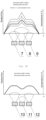
- fig. 3 shaping the profile of a temperature field by means of an amplitude of energy sources
- fig. 4 the use of lenses to shape the field of temperatures
- fig. 5 the dependence of temperature in a transverse cross-section of the plane
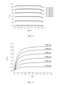
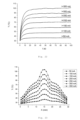
- fig. 6 temperature as a function of current for its various values
- fig. 7 the dependence of the value of temperature on the current supplying the heat source
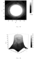
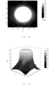
- fig. 8B a temperature profile for a current of 100 mA in a three-dimensional projection and its two-dimensional map
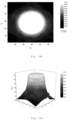
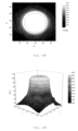
- fig. 9A and fig. 9B a temperature profile for a current of 200 mA in a three-dimensional projection and its two-dimensional map
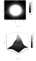
- fig. 10A and fig. 10B a temperature profile for a current of 300 mA in a three-dimensional projection and its two-dimensional map
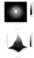
- fig. 11A and fig. 11B a temperature profile for a current of 400 mA in a three-dimensional projection and its two-dimensional map
- fig. 12A and 12B a temperature profile for a current of 500 mA in a three-dimensional projection and its two-dimensional map
- 13A and 13B a temperature profile for a current of 600 mA in a three-dimensional projection and its two-dimensional map
- 14A and fig. 14B a temperature profile for a current of 50 mA in a three-dimensional projection and its two-dimensional map for a system with a lens
- fig. 15A and fig. 15B a temperature profile for a current of 100 mA in a three-dimensional projection and its two-dimensional map for a system with a lens
- fig. 16A and fig. 16B a temperature profile for a current of 150 mA in a three-dimensional projection and its two-dimensional map for a system with a lens
- Fig. 1 Presents a method for controlling temperature by means of a specialised controller (3) with a microprocessor, at a volume point (with coordinates of ⁇ x, ⁇ y, ⁇ z), wherein the source of radiation (2) may be a laser, a LED diode or a piezoceramic transducer.
- a detector (1) according to the invention may be a pyroelectric or thermocouple sensor, absorbing radiation in the infrared range where the maximum of thermal radiation is placed.
- Figure 2 presents the use of a system of sources for shaping and controlling volumetric and planar temperature fields in spaces and on material surfaces as a function of time by using the superposition of various sources of radiant energy (4, 5, 6).
- FIG. 3A presents a situation when one of the sources of electromagnetic waves radiates with a higher amplitude, while fig. 3B - when the amplitude of radiation for one of the sources of electromagnetic waves is being reduced (10, 11, 12).
- Yet another embodiment of the invention enables the use of lenses (14) in order to multiply the effective source of radiant energy (13).
- lenses (14) By using various kinds of lenses and adjusting the number of radiant energy sources, it is possible to practically form any temperature profile in a volume or on a surface and control it as a function of time ( Fig. 4 ).
- Figure 5 presents the value of temperature measured for many points in a transverse cross-section of an irradiated plane as a function of current applied to the source of electromagnetic waves.
- fig. 6 presents changes in the measured temperature at a point as a function of time depending on the current applied to the source of electromagnetic waves.
- Figure 7 depicts a linear increase in the measured temperature as a function of current flowing through the source of electromagnetic waves.
- Figures from 8A to 13B present the shapes of temperature profiles on a planar surface for various values of current powering the sources of electromagnetic waves, created as a result of using the method according to the present invention.
- Figures from 14A to 20B present the shapes of temperature profiles on a planar surface for various values of current powering the sources of electromagnetic waves, created as a result of using the method according to the present invention in a system with a lens.
- Figure 21 depicts a linear increase in the measured temperature as a function of current flowing through the source of electromagnetic waves in a system with a lens.
- fig. 22 presents changes in the measured temperature at a point as a function of time depending on the current applied to the source of electromagnetic waves in a system with a lens.
- Figure 23 presents the value of temperature measured for many points in a transverse cross-section of an irradiated plane as a function of current applied to the source of electromagnetic waves upon placing a lens shaping the profile of the wavefront between the source and the irradiated surface.
- Figure 24 presents a comparison of a wavefront modified by means of a lens( ⁇ ) with a wavefront without a lens( ⁇ ).
- Figure 25 presents a measurement system comprising an MLX90614 detector (15), sources of electromagnetic radiation - LZ1-00DB05 diodes, a maximum working current of 1200 mA (16, 17) and a plane irradiated with electromagnetic radiation (18, a plate made of copper and covered with copper oxide) for shaping planar wavefronts.
- Figure 26 presents a measurement system comprising an MLX90614 detector (19), a source of electromagnetic radiation - a UV diode (20), a lens (21) and a plane irradiated with electromagnetic radiation (a planar plate made of polymer, 22) for shaping the wavefronts by means of a lens.
Landscapes
- Physics & Mathematics (AREA)
- General Physics & Mathematics (AREA)
- Spectroscopy & Molecular Physics (AREA)
- Engineering & Computer Science (AREA)
- Optics & Photonics (AREA)
- Automation & Control Theory (AREA)
- Plasma & Fusion (AREA)
- Mechanical Engineering (AREA)
- Radiation Pyrometers (AREA)
Applications Claiming Priority (2)
| Application Number | Priority Date | Filing Date | Title |
|---|---|---|---|
| PL424096A PL239727B1 (pl) | 2018-01-03 | 2018-01-03 | Zestaw do bezdotykowej kontroli temperatury, sposob generowania frontow falowych promieniowania elektromagnetycznego |
| PCT/PL2018/050068 WO2019135687A1 (en) | 2018-01-03 | 2018-12-19 | A set for contactless temperature control, a method of generating electromagnetic radiation wavefronts and the use of the set to generate profiles of temperature fields |
Publications (3)
| Publication Number | Publication Date |
|---|---|
| EP3735575A1 EP3735575A1 (en) | 2020-11-11 |
| EP3735575A4 EP3735575A4 (en) | 2021-10-27 |
| EP3735575B1 true EP3735575B1 (en) | 2025-02-19 |
Family
ID=67143729
Family Applications (1)
| Application Number | Title | Priority Date | Filing Date |
|---|---|---|---|
| EP18898287.0A Active EP3735575B1 (en) | 2018-01-03 | 2018-12-19 | A set for contactless temperature control, a method of generating electromagnetic radiation wavefronts and the use of the set to generate profiles of temperature fields |
Country Status (7)
| Country | Link |
|---|---|
| US (1) | US20210072777A1 (pl) |
| EP (1) | EP3735575B1 (pl) |
| JP (2) | JP7825940B2 (pl) |
| CN (1) | CN111556959A (pl) |
| ES (1) | ES3019683T3 (pl) |
| PL (2) | PL239727B1 (pl) |
| WO (1) | WO2019135687A1 (pl) |
Family Cites Families (24)
| Publication number | Priority date | Publication date | Assignee | Title |
|---|---|---|---|---|
| DE4114671A1 (de) * | 1991-05-06 | 1992-11-12 | Hoechst Ag | Verfahren und messanordnung zur beruehrungslosen on-line messung |
| DE4234342C2 (de) | 1992-10-12 | 1998-05-14 | Fraunhofer Ges Forschung | Verfahren zur Materialbearbeitung mit Laserstrahlung |
| JPH06300645A (ja) * | 1993-04-15 | 1994-10-28 | Japan Radio Co Ltd | 温度測定装置 |
| ES2106520T3 (es) * | 1993-05-19 | 1997-11-01 | Fraunhofer Ges Forschung | Procedimiento que permite el trabajo de materiales por radiacion emitida por diodos. |
| JPH0933353A (ja) * | 1995-07-24 | 1997-02-07 | Toru Inai | 放射測温方法およびその測温装置 |
| EP0836905B1 (de) * | 1996-10-20 | 2002-04-10 | INPRO Innovationsgesellschaft für fortgeschrittene Produktionssysteme in der Fahrzeugindustrie mbH | Verfahren und Anordnung zur temperaturgeregelten Oberflächenbehandlung, insbesondere zum Härten von Werkstückoberflächen mittels Laserstrahlung |
| US6002113A (en) * | 1998-05-18 | 1999-12-14 | Lucent Technologies Inc. | Apparatus for processing silicon devices with improved temperature control |
| US6122440A (en) | 1999-01-27 | 2000-09-19 | Regents Of The University Of Minnesota | Optical heating device for rapid thermal processing (RTP) system |
| US6830942B1 (en) * | 1999-04-06 | 2004-12-14 | Lucent Technologies Inc. | Method for processing silicon workpieces using hybrid optical thermometer system |
| JP3417399B2 (ja) * | 2001-01-17 | 2003-06-16 | 三菱電機株式会社 | 波面センサ |
| US7005601B2 (en) * | 2002-04-18 | 2006-02-28 | Applied Materials, Inc. | Thermal flux processing by scanning |
| US6768084B2 (en) * | 2002-09-30 | 2004-07-27 | Axcelis Technologies, Inc. | Advanced rapid thermal processing (RTP) using a linearly-moving heating assembly with an axisymmetric and radially-tunable thermal radiation profile |
| US6967342B2 (en) * | 2003-07-31 | 2005-11-22 | Fusion Uv Systems, Inc. | Method and apparatus for improved ultraviolet (UV) treatment of large three-dimensional (3D) objects |
| US20050106876A1 (en) * | 2003-10-09 | 2005-05-19 | Taylor Charles A.Ii | Apparatus and method for real time measurement of substrate temperatures for use in semiconductor growth and wafer processing |
| US8536492B2 (en) | 2003-10-27 | 2013-09-17 | Applied Materials, Inc. | Processing multilayer semiconductors with multiple heat sources |
| JP2005231262A (ja) | 2004-02-20 | 2005-09-02 | Keyence Corp | 紫外線照射装置、紫外線照射方法、紫外線照射条件設定プログラム及びコンピュータで読み取り可能な記録媒体並びに記憶した機器 |
| JP4864396B2 (ja) * | 2005-09-13 | 2012-02-01 | 株式会社東芝 | 半導体素子の製造方法、及び、半導体素子の製造装置 |
| US20160238453A1 (en) * | 2006-02-27 | 2016-08-18 | Yuriko Mizuta | Infrared sensor manufactured by method suitable for mass production |
| WO2008151469A1 (en) | 2007-06-15 | 2008-12-18 | Changxue Ren | Heating device and method using a pseudo-uniform electromagnetic field |
| JP2010048429A (ja) * | 2008-08-19 | 2010-03-04 | Panasonic Corp | 加熱調理器 |
| JP2011247980A (ja) * | 2010-05-25 | 2011-12-08 | Mitsubishi Electric Corp | マルチ画面表示装置 |
| JP2016001642A (ja) * | 2014-06-11 | 2016-01-07 | 坂口電熱株式会社 | レーザ加熱処理装置 |
| DE112015005598T5 (de) * | 2015-01-22 | 2017-09-28 | Olympus Corporation | Ultraschallbehandlungsvorrichtung |
| TWI673482B (zh) * | 2016-05-24 | 2019-10-01 | 美商應用材料股份有限公司 | 用於藉由布儒斯特角下的雙波長偏移進行的非接觸式溫度測量的系統、處理腔室與方法 |
-
2018
- 2018-01-03 PL PL424096A patent/PL239727B1/pl unknown
- 2018-12-19 ES ES18898287T patent/ES3019683T3/es active Active
- 2018-12-19 PL PL18898287.0T patent/PL3735575T3/pl unknown
- 2018-12-19 US US16/959,947 patent/US20210072777A1/en active Pending
- 2018-12-19 JP JP2020557112A patent/JP7825940B2/ja active Active
- 2018-12-19 CN CN201880084969.8A patent/CN111556959A/zh active Pending
- 2018-12-19 WO PCT/PL2018/050068 patent/WO2019135687A1/en not_active Ceased
- 2018-12-19 EP EP18898287.0A patent/EP3735575B1/en active Active
-
2024
- 2024-02-01 JP JP2024014082A patent/JP2024059644A/ja active Pending
Non-Patent Citations (2)
| Title |
|---|
| LASKIN ALEXANDER ET AL: "Refractive beam shapers for focused laser beams", PROCEEDINGS OF SPIE; [PROCEEDINGS OF SPIE ISSN 0277-786X VOLUME 10524], SPIE, US, vol. 9950, 27 September 2016 (2016-09-27), pages 995002 - 995002, XP060079719, ISBN: 978-1-5106-1533-5, DOI: 10.1117/12.2235712 * |
| SEIFERT M. ET AL: "B7.1 - Precise temperature calibration for laser heat treatment", PROCEEDINGS SENSOR 2013, 1 January 2013 (2013-01-01), pages 302 - 307, XP093082406, DOI: 10.5162/sensor2013/B7.1 * |
Also Published As
| Publication number | Publication date |
|---|---|
| JP7825940B2 (ja) | 2026-03-09 |
| WO2019135687A1 (en) | 2019-07-11 |
| PL239727B1 (pl) | 2022-01-03 |
| PL424096A1 (pl) | 2019-07-15 |
| JP2024059644A (ja) | 2024-05-01 |
| US20210072777A1 (en) | 2021-03-11 |
| ES3019683T3 (en) | 2025-05-21 |
| EP3735575A1 (en) | 2020-11-11 |
| PL3735575T3 (pl) | 2025-06-02 |
| CN111556959A (zh) | 2020-08-18 |
| EP3735575A4 (en) | 2021-10-27 |
| JP2021509959A (ja) | 2021-04-08 |
Similar Documents
| Publication | Publication Date | Title |
|---|---|---|
| US9617636B2 (en) | System and method for controlling wafer and thin film surface temperature | |
| US6610967B2 (en) | Rapid thermal processing chamber for processing multiple wafers | |
| JP5374521B2 (ja) | 温度検出装置、加熱装置、基板加熱方法 | |
| EP2714414B1 (en) | Apparatus and method for writing a pattern in a substrate | |
| KR20020019016A (ko) | 열처리 챔버의 고온계 교정 시스템 및 방법 | |
| Ren et al. | Apparatus for measuring spectral emissivity of solid materials at elevated temperatures | |
| RU2006147226A (ru) | Способ и устройство для изготовления трехмерного объекта | |
| DE69129814D1 (de) | Vorrichtung zum Laser-Strahlungsenergiesintern | |
| TWI816805B (zh) | 利用光束寬度調變的晶圓點加熱 | |
| CN115527896B (zh) | 旋转基板激光退火 | |
| US4634840A (en) | Method of heating thermoplastic resin sheet or film | |
| US9214368B2 (en) | Laser diode array with fiber optic termination for surface treatment of materials | |
| US20210183671A1 (en) | Optical heating device | |
| US20150292815A1 (en) | Susceptor with radiation source compensation | |
| EP3735575B1 (en) | A set for contactless temperature control, a method of generating electromagnetic radiation wavefronts and the use of the set to generate profiles of temperature fields | |
| JPH118204A (ja) | 高速ランプ加熱処理装置 | |
| US8575521B2 (en) | Monitoring witness structures for temperature control in RTP systems | |
| TW201632851A (zh) | 用於藉由折射及具有感磁性之波之速度上的改變來測量溫度的方法 | |
| HK40033092A (en) | A set for contactless temperature control, a method of generating electromagnetic radiation wavefronts and the use of the set to generate profiles of temperature fields | |
| JP4171817B2 (ja) | 熱物性測定方法及び装置 | |
| CN113203768A (zh) | 一种基于激光加热的各向异性材料的热导率测试方法 | |
| JPH07502821A (ja) | 加熱制御方法及び装置 | |
| EP3255421B1 (en) | Device for the contactless and non-destructive testing of a surface by measuring its infrared radiation | |
| Martsinukov et al. | Measurement of coating thickness using laser heating | |
| JPH0552445B2 (pl) |
Legal Events
| Date | Code | Title | Description |
|---|---|---|---|
| STAA | Information on the status of an ep patent application or granted ep patent |
Free format text: STATUS: THE INTERNATIONAL PUBLICATION HAS BEEN MADE |
|
| PUAI | Public reference made under article 153(3) epc to a published international application that has entered the european phase |
Free format text: ORIGINAL CODE: 0009012 |
|
| STAA | Information on the status of an ep patent application or granted ep patent |
Free format text: STATUS: REQUEST FOR EXAMINATION WAS MADE |
|
| 17P | Request for examination filed |
Effective date: 20200526 |
|
| AK | Designated contracting states |
Kind code of ref document: A1 Designated state(s): AL AT BE BG CH CY CZ DE DK EE ES FI FR GB GR HR HU IE IS IT LI LT LU LV MC MK MT NL NO PL PT RO RS SE SI SK SM TR |
|
| AX | Request for extension of the european patent |
Extension state: BA ME |
|
| DAV | Request for validation of the european patent (deleted) | ||
| DAX | Request for extension of the european patent (deleted) | ||
| A4 | Supplementary search report drawn up and despatched |
Effective date: 20210924 |
|
| RIC1 | Information provided on ipc code assigned before grant |
Ipc: G01J 5/00 20060101ALI20210920BHEP Ipc: G05D 23/27 20060101ALI20210920BHEP Ipc: H05B 6/00 20060101ALI20210920BHEP Ipc: B23K 26/06 20140101ALI20210920BHEP Ipc: G01J 5/02 20060101ALI20210920BHEP Ipc: G01J 5/12 20060101AFI20210920BHEP |
|
| RAP3 | Party data changed (applicant data changed or rights of an application transferred) |
Owner name: GENOMTEC SA |
|
| STAA | Information on the status of an ep patent application or granted ep patent |
Free format text: STATUS: EXAMINATION IS IN PROGRESS |
|
| 17Q | First examination report despatched |
Effective date: 20220712 |
|
| P01 | Opt-out of the competence of the unified patent court (upc) registered |
Effective date: 20230515 |
|
| REG | Reference to a national code |
Ref country code: DE Ref legal event code: R079 Free format text: PREVIOUS MAIN CLASS: G01J0005120000 Ipc: G01J0005020000 Ref country code: DE Ref legal event code: R079 Ref document number: 602018079451 Country of ref document: DE Free format text: PREVIOUS MAIN CLASS: G01J0005120000 Ipc: G01J0005020000 |
|
| GRAP | Despatch of communication of intention to grant a patent |
Free format text: ORIGINAL CODE: EPIDOSNIGR1 |
|
| STAA | Information on the status of an ep patent application or granted ep patent |
Free format text: STATUS: GRANT OF PATENT IS INTENDED |
|
| RIC1 | Information provided on ipc code assigned before grant |
Ipc: H05B 6/00 20060101ALI20241129BHEP Ipc: G05D 23/27 20060101ALI20241129BHEP Ipc: B23K 26/06 20140101ALI20241129BHEP Ipc: G01J 5/48 20060101ALI20241129BHEP Ipc: G01J 5/12 20060101ALI20241129BHEP Ipc: G01J 5/02 20060101AFI20241129BHEP |
|
| GRAS | Grant fee paid |
Free format text: ORIGINAL CODE: EPIDOSNIGR3 |
|
| INTG | Intention to grant announced |
Effective date: 20241216 |
|
| GRAA | (expected) grant |
Free format text: ORIGINAL CODE: 0009210 |
|
| STAA | Information on the status of an ep patent application or granted ep patent |
Free format text: STATUS: THE PATENT HAS BEEN GRANTED |
|
| AK | Designated contracting states |
Kind code of ref document: B1 Designated state(s): AL AT BE BG CH CY CZ DE DK EE ES FI FR GB GR HR HU IE IS IT LI LT LU LV MC MK MT NL NO PL PT RO RS SE SI SK SM TR |
|
| REG | Reference to a national code |
Ref country code: GB Ref legal event code: FG4D |
|
| REG | Reference to a national code |
Ref country code: CH Ref legal event code: EP |
|
| REG | Reference to a national code |
Ref country code: IE Ref legal event code: FG4D |
|
| REG | Reference to a national code |
Ref country code: DE Ref legal event code: R096 Ref document number: 602018079451 Country of ref document: DE |
|
| REG | Reference to a national code |
Ref country code: NL Ref legal event code: FP |
|
| REG | Reference to a national code |
Ref country code: ES Ref legal event code: FG2A Ref document number: 3019683 Country of ref document: ES Kind code of ref document: T3 Effective date: 20250521 |
|
| PG25 | Lapsed in a contracting state [announced via postgrant information from national office to epo] |
Ref country code: RS Free format text: LAPSE BECAUSE OF FAILURE TO SUBMIT A TRANSLATION OF THE DESCRIPTION OR TO PAY THE FEE WITHIN THE PRESCRIBED TIME-LIMIT Effective date: 20250519 |
|
| PG25 | Lapsed in a contracting state [announced via postgrant information from national office to epo] |
Ref country code: FI Free format text: LAPSE BECAUSE OF FAILURE TO SUBMIT A TRANSLATION OF THE DESCRIPTION OR TO PAY THE FEE WITHIN THE PRESCRIBED TIME-LIMIT Effective date: 20250219 |
|
| REG | Reference to a national code |
Ref country code: LT Ref legal event code: MG9D |
|
| PG25 | Lapsed in a contracting state [announced via postgrant information from national office to epo] |
Ref country code: NO Free format text: LAPSE BECAUSE OF FAILURE TO SUBMIT A TRANSLATION OF THE DESCRIPTION OR TO PAY THE FEE WITHIN THE PRESCRIBED TIME-LIMIT Effective date: 20250519 Ref country code: IS Free format text: LAPSE BECAUSE OF FAILURE TO SUBMIT A TRANSLATION OF THE DESCRIPTION OR TO PAY THE FEE WITHIN THE PRESCRIBED TIME-LIMIT Effective date: 20250619 |
|
| PG25 | Lapsed in a contracting state [announced via postgrant information from national office to epo] |
Ref country code: HR Free format text: LAPSE BECAUSE OF FAILURE TO SUBMIT A TRANSLATION OF THE DESCRIPTION OR TO PAY THE FEE WITHIN THE PRESCRIBED TIME-LIMIT Effective date: 20250219 |
|
| PG25 | Lapsed in a contracting state [announced via postgrant information from national office to epo] |
Ref country code: PT Free format text: LAPSE BECAUSE OF FAILURE TO SUBMIT A TRANSLATION OF THE DESCRIPTION OR TO PAY THE FEE WITHIN THE PRESCRIBED TIME-LIMIT Effective date: 20250620 Ref country code: LV Free format text: LAPSE BECAUSE OF FAILURE TO SUBMIT A TRANSLATION OF THE DESCRIPTION OR TO PAY THE FEE WITHIN THE PRESCRIBED TIME-LIMIT Effective date: 20250219 |
|
| PG25 | Lapsed in a contracting state [announced via postgrant information from national office to epo] |
Ref country code: GR Free format text: LAPSE BECAUSE OF FAILURE TO SUBMIT A TRANSLATION OF THE DESCRIPTION OR TO PAY THE FEE WITHIN THE PRESCRIBED TIME-LIMIT Effective date: 20250520 Ref country code: BG Free format text: LAPSE BECAUSE OF FAILURE TO SUBMIT A TRANSLATION OF THE DESCRIPTION OR TO PAY THE FEE WITHIN THE PRESCRIBED TIME-LIMIT Effective date: 20250219 |
|
| REG | Reference to a national code |
Ref country code: AT Ref legal event code: MK05 Ref document number: 1768660 Country of ref document: AT Kind code of ref document: T Effective date: 20250219 |
|
| PG25 | Lapsed in a contracting state [announced via postgrant information from national office to epo] |
Ref country code: SE Free format text: LAPSE BECAUSE OF FAILURE TO SUBMIT A TRANSLATION OF THE DESCRIPTION OR TO PAY THE FEE WITHIN THE PRESCRIBED TIME-LIMIT Effective date: 20250219 |
|
| PG25 | Lapsed in a contracting state [announced via postgrant information from national office to epo] |
Ref country code: SM Free format text: LAPSE BECAUSE OF FAILURE TO SUBMIT A TRANSLATION OF THE DESCRIPTION OR TO PAY THE FEE WITHIN THE PRESCRIBED TIME-LIMIT Effective date: 20250219 |
|
| PG25 | Lapsed in a contracting state [announced via postgrant information from national office to epo] |
Ref country code: DK Free format text: LAPSE BECAUSE OF FAILURE TO SUBMIT A TRANSLATION OF THE DESCRIPTION OR TO PAY THE FEE WITHIN THE PRESCRIBED TIME-LIMIT Effective date: 20250219 |
|
| PG25 | Lapsed in a contracting state [announced via postgrant information from national office to epo] |
Ref country code: AT Free format text: LAPSE BECAUSE OF FAILURE TO SUBMIT A TRANSLATION OF THE DESCRIPTION OR TO PAY THE FEE WITHIN THE PRESCRIBED TIME-LIMIT Effective date: 20250219 |
|
| PG25 | Lapsed in a contracting state [announced via postgrant information from national office to epo] |
Ref country code: EE Free format text: LAPSE BECAUSE OF FAILURE TO SUBMIT A TRANSLATION OF THE DESCRIPTION OR TO PAY THE FEE WITHIN THE PRESCRIBED TIME-LIMIT Effective date: 20250219 Ref country code: CZ Free format text: LAPSE BECAUSE OF FAILURE TO SUBMIT A TRANSLATION OF THE DESCRIPTION OR TO PAY THE FEE WITHIN THE PRESCRIBED TIME-LIMIT Effective date: 20250219 |
|
| PG25 | Lapsed in a contracting state [announced via postgrant information from national office to epo] |
Ref country code: RO Free format text: LAPSE BECAUSE OF FAILURE TO SUBMIT A TRANSLATION OF THE DESCRIPTION OR TO PAY THE FEE WITHIN THE PRESCRIBED TIME-LIMIT Effective date: 20250219 |
|
| PG25 | Lapsed in a contracting state [announced via postgrant information from national office to epo] |
Ref country code: SK Free format text: LAPSE BECAUSE OF FAILURE TO SUBMIT A TRANSLATION OF THE DESCRIPTION OR TO PAY THE FEE WITHIN THE PRESCRIBED TIME-LIMIT Effective date: 20250219 |
|
| REG | Reference to a national code |
Ref country code: DE Ref legal event code: R097 Ref document number: 602018079451 Country of ref document: DE |
|
| PLBE | No opposition filed within time limit |
Free format text: ORIGINAL CODE: 0009261 |
|
| STAA | Information on the status of an ep patent application or granted ep patent |
Free format text: STATUS: NO OPPOSITION FILED WITHIN TIME LIMIT |
|
| REG | Reference to a national code |
Ref country code: CH Ref legal event code: L10 Free format text: ST27 STATUS EVENT CODE: U-0-0-L10-L00 (AS PROVIDED BY THE NATIONAL OFFICE) Effective date: 20251231 |
|
| REG | Reference to a national code |
Ref country code: CH Ref legal event code: U11 Free format text: ST27 STATUS EVENT CODE: U-0-0-U10-U11 (AS PROVIDED BY THE NATIONAL OFFICE) Effective date: 20260101 |
|
| PGFP | Annual fee paid to national office [announced via postgrant information from national office to epo] |
Ref country code: GB Payment date: 20251229 Year of fee payment: 8 |
|
| PGFP | Annual fee paid to national office [announced via postgrant information from national office to epo] |
Ref country code: IT Payment date: 20251218 Year of fee payment: 8 |
|
| PGFP | Annual fee paid to national office [announced via postgrant information from national office to epo] |
Ref country code: NL Payment date: 20251222 Year of fee payment: 8 Ref country code: FR Payment date: 20251230 Year of fee payment: 8 |
|
| PGFP | Annual fee paid to national office [announced via postgrant information from national office to epo] |
Ref country code: PL Payment date: 20251128 Year of fee payment: 8 |
|
| 26N | No opposition filed |
Effective date: 20251120 |
|
| PGFP | Annual fee paid to national office [announced via postgrant information from national office to epo] |
Ref country code: ES Payment date: 20260122 Year of fee payment: 8 |
|
| PGFP | Annual fee paid to national office [announced via postgrant information from national office to epo] |
Ref country code: DE Payment date: 20251229 Year of fee payment: 8 |