EP3735702B1 - Transformateur de courant ouvrant a noyau magnetique souple - Google Patents
Transformateur de courant ouvrant a noyau magnetique souple Download PDFInfo
- Publication number
- EP3735702B1 EP3735702B1 EP18842807.2A EP18842807A EP3735702B1 EP 3735702 B1 EP3735702 B1 EP 3735702B1 EP 18842807 A EP18842807 A EP 18842807A EP 3735702 B1 EP3735702 B1 EP 3735702B1
- Authority
- EP
- European Patent Office
- Prior art keywords
- current transformer
- wires
- magnetic circuit
- coil
- winding
- Prior art date
- Legal status (The legal status is an assumption and is not a legal conclusion. Google has not performed a legal analysis and makes no representation as to the accuracy of the status listed.)
- Active
Links
Images

Classifications
-
- H—ELECTRICITY
- H01—ELECTRIC ELEMENTS
- H01F—MAGNETS; INDUCTANCES; TRANSFORMERS; SELECTION OF MATERIALS FOR THEIR MAGNETIC PROPERTIES
- H01F27/00—Details of transformers or inductances, in general
- H01F27/42—Circuits specially adapted for the purpose of modifying, or compensating for, electric characteristics of transformers, reactors, or choke coils
- H01F27/422—Circuits specially adapted for the purpose of modifying, or compensating for, electric characteristics of transformers, reactors, or choke coils for instrument transformers
- H01F27/427—Circuits specially adapted for the purpose of modifying, or compensating for, electric characteristics of transformers, reactors, or choke coils for instrument transformers for current transformers
-
- H—ELECTRICITY
- H01—ELECTRIC ELEMENTS
- H01F—MAGNETS; INDUCTANCES; TRANSFORMERS; SELECTION OF MATERIALS FOR THEIR MAGNETIC PROPERTIES
- H01F38/00—Adaptations of transformers or inductances for specific applications or functions
- H01F38/20—Instruments transformers
- H01F38/22—Instruments transformers for single phase AC
- H01F38/28—Current transformers
- H01F38/30—Constructions
-
- H—ELECTRICITY
- H01—ELECTRIC ELEMENTS
- H01F—MAGNETS; INDUCTANCES; TRANSFORMERS; SELECTION OF MATERIALS FOR THEIR MAGNETIC PROPERTIES
- H01F27/00—Details of transformers or inductances, in general
- H01F27/28—Coils; Windings; Conductive connections
- H01F27/2823—Wires
-
- H—ELECTRICITY
- H01—ELECTRIC ELEMENTS
- H01F—MAGNETS; INDUCTANCES; TRANSFORMERS; SELECTION OF MATERIALS FOR THEIR MAGNETIC PROPERTIES
- H01F27/00—Details of transformers or inductances, in general
- H01F27/28—Coils; Windings; Conductive connections
- H01F27/32—Insulating of coils, windings, or parts thereof
- H01F27/324—Insulation between coil and core, between different winding sections, around the coil; Other insulation structures
-
- H—ELECTRICITY
- H01—ELECTRIC ELEMENTS
- H01F—MAGNETS; INDUCTANCES; TRANSFORMERS; SELECTION OF MATERIALS FOR THEIR MAGNETIC PROPERTIES
- H01F3/00—Cores, Yokes, or armatures
- H01F3/06—Cores, Yokes, or armatures made from wires
-
- H—ELECTRICITY
- H01—ELECTRIC ELEMENTS
- H01F—MAGNETS; INDUCTANCES; TRANSFORMERS; SELECTION OF MATERIALS FOR THEIR MAGNETIC PROPERTIES
- H01F38/00—Adaptations of transformers or inductances for specific applications or functions
- H01F38/20—Instruments transformers
- H01F38/22—Instruments transformers for single phase AC
- H01F38/28—Current transformers
- H01F38/30—Constructions
- H01F2038/305—Constructions with toroidal magnetic core
Definitions
- the invention relates to a device for measuring an electric current, and more particularly a measuring device comprising a current transformer provided with a flexible opening magnetic circuit in the shape of a torus and capable of closing on a cable in which the current to be measured.
- a Rogowski toroid is an air-core electrotechnical device for measuring alternating current or high-speed current pulses.
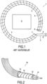
- a Rogowski winding 1 is conventionally composed of an electric wire 2 comprising a first part 3 wound helically around a sheath 4, and a second part 5 secured to a first end 6 of the first part 3, the second part 5 of the wire 2 passing through the helical winding 3, and therefore the sheath 4, along its winding axis over the entire axial length of the helical winding up to a second end 7 of the first part 3 of the wire 2, so that the two electrical terminals 8 and 9 of the electrical wire 2 are at the same end of the Rogowski winding 1.
- the Rogowski coil 1 is positioned around the conductor C whose current we want to know.
- the voltage induced in the winding is proportional to the rate of change (derivative) of the current in the conductor.
- the advantage of a Rogowski toroid compared to other types of current sensors is its good flexibility mainly thanks to the absence of a rigid metal core, a property that other current sensors have little or no . This flexibility allows it to be wound around one or more phase conductors without constraint.
- the flexible opening toroids of the Rogowski type have the desired mechanical properties, they do not however present the performances compatible with all areas of application in particular for using this sensor on an IT type neutral regime (impedant neutral) in which the measurement of differential currents is often at a very low level and at low frequencies.
- a known solution is proposed in the patent EP 0 999 565 . It is a current transformer comprising a winding wound around a magnetic circuit made up of a stack of flat strips free between them and very loosely held and fixed at each end. The magnetic circuit is electrically isolated from the winding, the transformer is configured to connect the two ends of the magnetic circuit together when the current transformer is closed around the electrical conductor on which the current measurement is to be carried out.
- the magnetic circuit is not flexible in all principal directions equally.
- the absence of the same flexibility in all the main directions does not allow easy implementation of the measurement system.
- the movement of the bands causes variations in the apparent section of the magnetic core which are harmful to performance.
- controlling the constancy of the section of the magnetic core allows repeatability of the measurement in any geometric configuration of the sensor.
- the precision of such a device is low, especially for the measurement of low intensity currents, to the point that the measurement, or even the detection, of currents lower than a few milliamps is impossible.
- the invention aims to overcome the drawbacks mentioned above by proposing a current transformer equipped with a flexible magnetic circuit in all the main directions in an identical manner and while retaining the performance of measuring electric currents of very low amplitude and of low frequencies and low manufacturing cost.
- a current transformer in the shape of an opening torus intended to close on an electrical conductor in which an electric current to be measured circulates or on several electrical conductors in which electric currents circulate, the sum of which is to be measured vector, the current transformer comprising a magnetic circuit and an electrically conductive winding wound around and electrically isolated from the magnetic circuit, the winding comprising a single winding or several distinct windings coupled in series.
- the magnetic circuit comprises a set of wires of magnetic material, the wires being assembled together in the form of a strand.
- a device with a flexible magnetic core allows accessibility to measurement points in particularly confined or narrow places.
- the assembly of the wires in the form of a strand provides the magnetic circuit, and by extension the transformer, with uniform flexibility in all directions, and thus flexibility identical to that of a metal cable.
- the invention comprises a plurality of distinct wires twisted together to form a magnetic cable around which the winding is electrically wound conductor, the cable having two ends which can be connected together to form a closed annular shape intended to be crossed by an electrical conductor to be measured.
- the magnetic material of the wires can be an Iron-Nickel alloy with high magnetic permeability with at least 70% Nickel, and preferably between 78 and 81% Nickel.
- the wires are mechanically insulated from each other by magnesium methoxide, or by alumina (Al 2 O 3 ) or magnesia (Mg0) powder during their assembly to avoid sticking between the sons.
- the wires are free from each other.
- the device is thus easily deformable without losing its characteristics.
- each wire comprises a plurality of strands of magnetic material twisted together in the form of a strand.
- Each wire thus forms a strand of strands of magnetic material.
- the wires are then twisted together to form the magnetic circuit cable in the form of a strand of wires.
- the strands of each wire are mechanically insulated from each other by magnesium methoxide, or by powder alumina (Al 2 O 3 ) or magnesia (Mg0) during their assembly to avoid sticking between the strands of the wires.
- the strands are free in relation to each other, which improves the flexibility characteristics of the cable.
- each strand of the wires may have a diameter of between 0.1 mm and 0.5 mm and preferably a diameter of 0.20 mm.
- the transformer can further comprise an electrically insulating flexible tubular internal sheath on which said winding is wound and in which the magnetic circuit is fitted.
- the transformer can further comprise an electrically insulating tubular external sheath enveloping said winding to protect the winding from the external environment both from any external electrical contact and from possible shock.
- the winding can comprise a plurality of distinct windings coupled in series, at least two windings comprising enameled conductive wire, that is to say covered with an electrically insulating coating, and being radially superimposed to form a stack in a radial direction relative to the winding axis of the winding.
- said at least one winding of the winding may comprise a copper electrical wire having a diameter of between 0.2 mm and 0.8 mm and preferably 0.4 mm.
- the transformer may comprise means of closing by snap-fastening or screwing.
- a device for measuring an electric current comprising a split current transformer as defined above, and processing means electrically coupled to the winding of the current transformer.
- FIG 2 is shown schematically a partial perspective view with partial cutaway of a current transformer 10 according to one embodiment of the invention.
- the current transformer 10 has the shape of an opening torus intended to close on an electrical conductor in which an electrical current, alternating or direct, to be measured circulates or on several electrical conductors in which electrical currents circulate, the vector sum of which is to be measured .
- the current transformer 10 comprises a magnetic circuit 11 inserted in an electrically insulating and flexible tubular internal sheath 12.
- the magnetic circuit 11 is formed of a plurality of wires 110 of magnetic material, for example wires of an alloy comprising 15% iron, 80% nickel, and 5% molybdenum.
- the magnetic circuit 11 comprises seven wires 110.
- the seven wires 110 are assembled together in the form of a strand to form a cable.
- the cable forming the magnetic circuit may comprise two wires or several dozen wires.
- Each wire 110 can be formed from a plurality of strands of magnetic material twisted together. Each wire 110 thus forms a strand of strands of magnetic material, and each strand formed by a wire 110 is assembled with the other wires 110 of the magnetic circuit to form a strand of wires 110 forming the cable 11.
- the strands from which the wires 110 are formed are made of an Iron-Nickel-Molybdenum alloy with high magnetic permeability having 80% Nickel.
- the wires 110 can have sections of various sizes, for example a section of 4.6 mm 2 .
- the cable of the magnetic circuit 11 may comprise several wires 110 each formed of several strands each having a diameter of approximately 0.2 mm to form a cable having an iron section of approximately 0.3 cm 2 .
- the number of strands in each wire 110 and the structure of the strand forming the magnetic cable 11, in particular the number of wires 110 composing the cable of the magnetic circuit 11, are adaptable depending on the sensitivity sought and the size envisaged for the cable of the magnetic circuit 11.
- magnetic circuit 11. Cable 11 is flexible in all directions thanks to its strand structure.
- the cable 11 undergoes heat treatment at high temperature under a reducing gas, such as hydrogen, so as to restore and optimize the magnetic performance of the material.
- a reducing gas such as hydrogen
- Each wire 110 is geometrically and electrically insulated before annealing the heat treatment phase of the cable 11 in order to avoid sticking between the wires during the heat treatment.
- This insulation operation is carried out using magnesium methoxide or alumina powder (Al 2 O 3 ) or magnesia (MgO), or another technology, or by direct application to the wire before the formation of the strand of wires 110 forming the cable 11 or either by application to the cable 11 after the formation of the strand of wires 110.
- the insulation operation is carried out on the strands either before the formation of the wires, or well after the formation of the wires 110 but before the formation of the cable 11, or even after the formation of the cable 11, the treatment being a chemical treatment which can reach the entire surface of a strand by capillarity even once after the cable has been shape.
- the insulation of each strand thus allows sliding between the strands and thus improves the flexibility characteristics of the cable 11.
- the cable 11 is then cut to the desired length and then has two ends 111 and 112.
- the two ends 111 and 112 of the cable 11 are crimped in order to hold the wires 110 together.
- the two sections at the ends 111 and 112 are intended to be opposite and in contact when the current transformer 10 is closed, as is illustrated on the figures 3 and 4 in particular, to form a closed magnetic circuit.
- the two sections at the ends 111 and 112 of the cable 11 are polished so as to optimize the air gap by ensuring good roughness, good parallelism and the least disturbed area possible from a magnetic point of view.
- the tubular internal sheath 12 forms a sleeve crossed axially, that is to say along the axis of revolution of the sheath 12, by the magnetic circuit 11, that is to say by the cable.
- the internal sheath 12 is a tube of insulating material sufficiently strong to support the winding of a copper wire with a diameter of notably between 0.20 and 0.8 mm while having sufficient flexibility to maintain that of the cable 11.
- the internal sheath 12 can be a tube made of PVC, Rylsan ® or other material, with an internal diameter of between 10 and 25 mm and a wall thickness of between 1 and 2 mm.
- the current transformer 10 further comprises an electrically conductive winding 13.
- the internal sheath 12 forms a winding support for the winding 13.
- the winding 13 is formed by a copper wire wound around the internal sheath 12 back and forth on the entire length of the magnetic circuit 11. In other words, the winding 13 is wound a first time from the first end 111 of the cable to the second end 112 of the cable 11 then a second time from the second end 112 of the cable 11 to the first end 111 of the cable 11. Enameling the copper wire of the winding makes it possible to insulate the wire and avoid any short circuit, particularly between the superimposed portions.
- the winding 13 may comprise a plurality of copper windings coupled together in series.
- the winding 13 has a first end 131 and a second end 132 opposite the first end 131.
- the winding 13 being wound back and forth around the internal sheath 12, the first and second ends 131 and 132 of the winding 13 are located at the same end of the cable 11 which is the first end 111 of the cable 11 in the example illustrated in the Figure 4 .
- the winding 13 can comprise 1000 turns wound regularly around the internal sheath 12 back and forth over a length which can be adapted depending on the size of the primary conductors and which can be between 200 and 2000 mm so as to constitute, after closing the current transformer 10, loops whose diameter is between 70 and 700 mm.
- the current transformer 10 further comprises an electrically insulating tubular outer sheath 14.
- the external sheath 14 is fitted onto the assembly comprising the cable 11, the internal sheath 12 and the winding 13 so as to envelop the winding 13 and isolate it from the external electrical environment of the current transformer 10.
- FIG. 3 schematically presents a view of the means 15 for closing the current transformer 10 according to one embodiment of the invention.
- the current transformer 10 also includes, in this embodiment, means 15 for closing by snap-fastening comprising a male part 150 mounted on a first end 101 of the current transformer 10 and a female part 155 complementary to the male part 150 and mounted on a second end 102 of the current transformer 10 opposite the first end 101 of the current transformer 10.
- the first end 111 of the cable 11 and the first and second ends 131 and 132 of the winding 13 are located on the first end 101 of the current transformer 10 while the second end 112 of the cable 11 is located on the second end 102 of the current transformer 10.
- the female part 155 comprises a tubular shape and circular grooves 156 formed on the radially internal surface of the tube of the female part 155.
- the male part 150 comprises a cylindrical shape configured to be inserted into the tubular shape of the female part 155.
- the male part 150 further comprises circular serrations configured to cooperate with the grooves 156 of the female part 155 to close the current transformer 10.
- the current transformer may comprise means of closing by screwing.
- the quality of the assembly is evaluated by measuring the magnetic permeability: with a sufficiently rigid closing device the permeability of the assembled cut circuit can be between 15,000 and 20,000.
- the closing device 15 is such that the sensor is easy to open without special tools.
- FIG. 4 is schematically represented a device for measuring an electric current comprising a current transformer 10 in the form of an opening toroid and processing means 16 electrically coupled to the two ends 131 and 132 of the winding 13.
- the processing means 16 make it possible to receive the current induced in the winding 13 of the current transformer 10 and thus carry out the measurement of the electric current passing through the electrical conductor around which the current transformer 10 has been closed.
- the invention thus provides a Rogowski type current transformer equipped with a flexible magnetic circuit in all the main directions in an identical manner, while maintaining the performance of measuring electric currents of very low amplitude and low frequencies and a low manufacturing cost, and a measuring device equipped with such a current transformer.
Landscapes
- Engineering & Computer Science (AREA)
- Power Engineering (AREA)
- Transformers For Measuring Instruments (AREA)
- Measuring Instrument Details And Bridges, And Automatic Balancing Devices (AREA)
Description
- L'invention concerne un dispositif de mesure d'un courant électrique, et plus particulièrement un dispositif de mesure comportant un transformateur de courant pourvu d'un circuit magnétique ouvrant souple en forme de tore et susceptible de se refermer sur un câble dans lequel circule le courant à mesurer.
- Un tore de Rogowski est un dispositif électrotechnique à noyau d'air permettant de mesurer le courant alternatif ou les impulsions de courant à grande vitesse. Comme cela est illustré sur la
figure 1 , un enroulement de Rogowski 1 se compose classiquement d'un fil électrique 2 comprenant une première partie 3 enroulée hélicoïdalement autour d'une gaine 4, et une seconde partie 5 solidaire d'une première extrémité 6 de la première partie 3, la seconde partie 5 du fil 2 traversant l'enroulement hélicoïdal 3, et donc la gaine 4, selon son axe d'enroulement sur toute la longueur axiale de l'enroulement hélicoïdale jusque à une seconde extrémité 7 de la première partie 3 du fil 2, de sorte que les deux bornes électriques 8 et 9 du fil électrique 2 soient à la même extrémité de l'enroulement de Rogowski 1. - La bobine de Rogowski 1 est positionnée autour du conducteur C dont on veut connaître le courant. La tension induite dans l'enroulement est proportionnelle au taux de changement (dérivée) du courant dans le conducteur.
- L'avantage d'un tore de Rogowski par rapport à d'autres types de capteurs de courants est sa bonne flexibilité principalement grâce à l'absence d'un noyau métallique rigide, propriété que les autres capteurs de courant n'ont pas ou peu. Cette flexibilité lui permet d'être enroulé autour d'un ou plusieurs conducteurs de phase sans contrainte.
- Cependant, si les tores souples ouvrant de type Rogowski possèdent les propriétés mécaniques recherchées, ils ne présentent toutefois pas les performances compatibles avec tous les domaines d'application notamment pour utiliser ce capteur sur un régime de neutre de type IT (neutre impédant) dans lequel la mesure de courants différentiels est à un niveau souvent très faible et de basses fréquences.
- Il est connu des dispositifs à noyau ferromagnétique, plutôt qu'à noyau d'air, permettant de pallier cet inconvénient. Ces types de tore connus comportent le plus souvent un circuit magnétique en deux parties rigides dont les performances correspondent à celles du besoin d'application mais présentent non seulement les inconvénients liés à leur encombrement et à leur rigidité, mais aussi ceux liés à la présence de deux entrefers. Pour limiter les effets des entrefers dans le dispositif, il est connu qu'il faut, d'une part, augmenter l'encombrement, c'est-à-dire augmenter la section du circuit magnétique, et, d'autre part, polir les surfaces des entrefers.
- Cette solution présentent des performances compatibles avec les domaines d'application mais la rigidité et l'encombrement de l'ensemble des dispositifs connus interdisent certaines accessibilités aux mesures.
- Une solution connue est proposée dans le brevet
EP 0 999 565 . Il s'agit d'un transformateur de courant comprenant un bobinage enroulé autour d'un circuit magnétique constitué d'un empilement de bandes plates libres entre elles et très peu maintenues et fixées à chaque extrémité. Le circuit magnétique est isolé électriquement du bobinage, le transformateur est configuré pour raccorder ensemble les deux extrémités du circuit magnétique lorsque le transformateur de courant de est fermé autour du conducteur électrique sur lequel la mesure de courant doit être réalisée. - Cependant, dans une telle solution, le circuit magnétique n'est pas souple dans toutes les directions principales de manière identique. Or, l'absence de la même souplesse dans toutes les directions principales ne permet pas une mise en place aisée du dispositif de mesures.
- De plus, le déplacement des bandes provoque des variations de la section apparente du noyau magnétique nuisibles à la performance. Or, la maîtrise de la constance de la section du noyau magnétique permet une répétitivité de la mesure dans toute configuration géométrique du capteur.
- En outre, la précision d'un tel dispositif est faible surtout pour la mesure des courants de faible intensité, au point que la mesure, voire la détection, de courant inférieur à quelques milliampères est impossible.
- Une autre solution connue, basée sur l'effet Néel, résout les problèmes précédemment mentionnés en utilisant un noyau magnétique en polymère chargé de particules super-paramagnétiques.
- Cependant, cette solution possède un coût élevé de fabrication.
- Il est également connu du document
US 5 235 488 un transformateur de courant comportant un circuit magnétique et un bobinage enroulé autour du circuit magnétique, le circuit magnétique comprenant un unique fil magnétique bobiné sous forme tubulaire pour former un tube destiné à être traversé par un conducteur électrique dans lequel circule un courant électrique à mesurer. - L'invention vise à pallier les inconvénients mentionnés ci-dessus en proposant un transformateur de courant doté d'un circuit magnétique souple dans toutes les directions principales de manière identique et tout en conservant les performances de mesure de courants électriques de très faible amplitude et de basses fréquences et un faible coût de fabrication.
- Dans l'invention, il est proposé un transformateur de courant en forme de tore ouvrant destiné à se refermer sur un conducteur électrique dans lequel circule un courant électrique à mesurer ou sur plusieurs conducteurs électriques dans lesquels circulent des courants électriques dont on veut mesurer la somme vectorielle, le transformateur de courant comportant un circuit magnétique et un bobinage électriquement conducteur enroulé autour et électriquement isolé du circuit magnétique , le bobinage comprenant un unique enroulement ou plusieurs enroulements distincts couplés en série.
- Selon l'invention, le circuit magnétique comprend un ensemble de fils de matériau magnétique, les fils étant assemblés ensemble sous forme de toron.
- Un dispositif à noyau magnétique souple autorise l'accessibilité à des point de mesures dans des endroits particulièrement confinés ou étroits. L'assemblage des fils sous forme de toron fournit au circuit magnétique, et par extension au transformateur, une souplesse uniforme dans toutes les directions, et ainsi une souplesse identique à celle d'un câble métallique.
- Contrairement à un transformateur de courant ayant un unique fil magnétique enroulé pour former une tube destiné à être traversé par le conducteur à mesurer, l'invention comprend une pluralité de fils distincts et torsadés ensemble pour former un câble magnétique autour duquel est enroulé le bobinage électriquement conducteur, le câble présentant deux extrémités qui peuvent être connectées ensemble pour former une forme annulaire fermée destinée à être traversée par un conducteur électrique à mesurer.
- Selon un premier aspect du transformateur de courant, le matériau magnétique des fils peut être un alliage de Fer-Nickel à haute perméabilité magnétique avec au moins 70% de Nickel, et de préférence entre 78 et 81% de Nickel.
- L'utilisation d'un matériau magnétique à haute perméabilité convenablement mis en oeuvre au niveau de l'isolation entre fils, du recuit magnétique et de la maîtrise de l'entrefer, permet d'obtenir une sensibilité et une précision élevée.
- L'utilisation d'un matériau à haute perméabilité magnétique ainsi que la mise en oeuvre de procédés de fabrication soignés permet en outre de garantir des caractéristiques électriques élevées en terme de précision et de sensibilité.
- Selon un deuxième aspect du transformateur de courant, les fils sont mécaniquement isolés les uns des autres par méthylate de magnésium, ou par poudre d'alumine (Al2O3) ou de magnésie (Mg0) lors de leur assemblage pour éviter les collages entre les fils.
- Les fils sont libres les uns par rapport aux autres. Le dispositif est ainsi facilement déformable sans perdre ses caractéristiques.
- Selon un troisième aspect du transformateur de courant, chaque fil comprend une pluralité de brins en matériau magnétique torsadés ensemble sous forme de toron.
- Chaque fil forme ainsi un toron de brins en matériau magnétique. Les fils sont ensuite torsadés ensemble pour former le câble du circuit magnétique sous la forme d'un toron de fils.
- Dans un mode de réalisation du troisième aspect du transformateur de courant, les brins de chaque fil sont mécaniquement isolés les uns des autres par méthylate de magnésium, ou par poudre d'alumine (Al2O3) ou de magnésie (Mg0) lors de leur assemblage pour éviter les collages entre les brins des fils.
- Ainsi, à l'intérieur de chaque fil, les brins sont libres les uns par rapport aux autres ce qui améliore les caractéristiques de souplesse du câble.
- Dans un autre mode de réalisation du troisième aspect du transformateur de courant, chaque brin des fils peut présenter un diamètre compris entre 0,1 mm et 0,5 mm et de préférence un diamètre de 0,20 mm.
- Selon un quatrième aspect du transformateur de courant, le transformateur peut comprendre en outre une gaine interne tubulaire souple électriquement isolante sur laquelle est enroulé ledit bobinage et dans laquelle est emmanché le circuit magnétique.
- Selon un cinquième aspect du transformateur de courant, le transformateur peut comprendre en outre une gaine externe tubulaire électriquement isolante enveloppant ledit bobinage pour protéger le bobinage de l'environnement externe aussi bien de tout contact électrique externe que d'éventuel choc.
- Selon un sixième aspect du transformateur de courant, le bobinage peut comprendre une pluralité d'enroulements distincts couplés en série, au moins deux enroulements comprenant du fil conducteur émaillé, c'est-à-dire recouvert d'un revêtement électriquement isolant, et étant radialement superposés pour former un empilement dans une direction radiale par rapport à l'axe d'enroulement du bobinage.
- Selon un septième aspect du transformateur de courant, ledit au moins un enroulement du bobinage peut comprendre un fil électrique de cuivre présentant un diamètre compris entre 0,2 mm et 0,8 mm et de préférence 0,4 mm.
- Plus le diamètre du fil de cuivre du bobinage est élevé plus le ratio entre l'inductance et la résistance du bobinage est grand, et ainsi meilleur, ce ratio influant directement sur la précision du transformateur de courant.
- Selon un huitième aspect du transformateur de courant, le transformateur peut comprendre des moyens de fermeture par encliquetage ou vissage.
- Dans un autre objet de l'invention, il est proposé un dispositif de mesure d'un courant électrique comprenant un transformateur de courant ouvrant tel que défini ci-dessus, et des moyens de traitement électriquement couplés au bobinage du transformateur de courant.
- L'invention sera mieux comprise à la lecture faite ci-après, à titre indicatif mais non limitatif, en référence aux dessins annexés sur lesquels :
- la
figure 1 , déjà décrite, présente schématiquement un enroulement de Rogowski selon l'état de la technique ; - la
figure 2 représente schématiquement une vue partielle en perspective avec arrachement partiel d'un transformateur de courant 10 selon un mode de réalisation de l'invention ; - la
figure 3 présente schématiquement une vue des moyens de fermetures du transformateur de courant selon un mode de réalisation de l'invention ; - la
figure 4 représente schématiquement un dispositif de mesure d'un courant électrique comprenant un transformateur de courant selon un mode de réalisation de l'invention. - Sur la
figure 2 est représenté schématiquement une vue partielle en perspective avec arrachement partiel d'un transformateur de courant 10 selon un mode de réalisation de l'invention. - Le transformateur de courant 10 possède une forme de tore ouvrant destiné à se refermer sur un conducteur électrique dans lequel circule un courant électrique, alternatif ou continu, à mesurer ou sur plusieurs conducteurs électriques dans lesquels circulent des courants électriques dont on veut mesurer la somme vectorielle.
- Le transformateur de courant 10 comprend un circuit magnétique 11 inséré dans une gaine interne 12 tubulaire électriquement isolante et souple.
- Le circuit magnétique 11 est formé d'une pluralité de fils 110 de matériau magnétique, par exemple des fils en un alliage comprenant 15% de Fer, 80% de Nickel, et 5% de Molybdène. Dans le mode de réalisation illustré sur la
figure 2 , le circuit magnétique 11 comprend sept fils 110. Les sept fils 110 sont assemblés ensemble sous forme de toron pour former un câble. Dans d'autres modes de réalisation, le câble formant le circuit magnétique peut comprendre deux fils ou bien plusieurs dizaines de fils. - Chaque fil 110 peut être formé d'une pluralité de brins en matériau magnétique torsadés ensemble. Chaque fil 110 forme ainsi un toron de brins en matériau magnétique, et chaque toron formé par un fil 110 est assemblé avec les autres fils 110 du circuit magnétique pour former un toron de fils 110 formant le câble 11.
- Dans le cas où les fils sont des fils multibrins, les brins à partir desquels sont formés les fils 110 sont fabriqués dans un alliage de Fer-Nickel-Molybdène à haute perméabilité magnétique ayant 80% de Nickel. Les fils 110 peuvent présenter des sections de taille diverses, par exemple une section de 4,6 mm2.
- Dans un exemple de réalisation, le câble du circuit magnétique 11 peut comprendre plusieurs fils 110 formés chacun de plusieurs brins présentant chacun un diamètre d'environ 0,2 mm pour former un câble présentant une section fer d'environ 0,3 cm2.
- Le nombre de brins dans chaque fil 110 et la structure du toron formant le câble magnétique 11, notamment le nombre de fils 110 composant le câble du circuit magnétique 11, sont adaptables en fonction de la sensibilité recherchée et de la taille envisagée pour le câble du circuit magnétique 11. Le câble 11 est souple dans toutes les directions grâce à sa structure en toron.
- A la suite de la formation mécanique du toron de fils 110, le câble 11 subit un traitement thermique à haute température sous gaz réducteur, tel que de l'hydrogène, de façon à restaurer et optimiser les performances magnétiques de la matière. La perméabilité intrinsèque obtenue dans le mode de réalisation de l'invention illustré sur la
figure 2 est supérieure à 105. - Chaque fil 110 est isolé géométriquement et électriquement avant le recuit de la phase de traitement thermique du câble 11 afin d'éviter les collages entre les fils pendant le traitement thermique. Cette opération d'isolation est réalisée à partir de méthylate de magnésium ou de poudre d'alumine (Al2O3) ou de magnésie (MgO), ou d'une autre technologie, soit par application directe sur le fil avant la formation du toron de fils 110 formant le câble 11 ou soit par application sur le câble 11 après la formation du toron de fils 110.
- Dans le cas où les fils 110 sont des fils multibrins, autrement dit lorsque chaque fil 110 est formé à partir d'une pluralité de brins torsadés ensemble, l'opération d'isolation est réalisée sur les brins soit avant la formation des fils, ou bien après la formation des fils 110 mais avant la formation du câble 11, ou encore après la formation du câble 11, le traitement étant un traitement chimique pouvant atteindre toute la surface d'un brin par capillarité même une fois après que le câble a été formé. L'isolation de chaque brin permet ainsi de permettre un coulissement entre les brins et ainsi d'améliorer les caractéristiques de souplesse du câble 11.
- Après le traitement thermique, le câble 11 est ensuite tronçonné à la longueur souhaitée et possède alors deux extrémités 111 et 112.Les deux extrémités 111 et 112 du câble 11 sont serties afin de maintenir les fils 110 entre eux. Les deux sections aux extrémités 111 et 112 sont destinées à être en vis-à-vis et en contact lorsque le transformateur de courant 10 est fermé, comme cela est illustré sur les
figures 3 et 4 notamment, pour former un circuit magnétique fermé. Les deux sections aux extrémités 111 et 112 du câble 11 sont polies de façon à optimiser l'entrefer en assurant une bonne rugosité, un bon parallélisme et une zone la moins perturbée possible du point de vue magnétique. - La gaine interne 12 tubulaire forme un manchon traversé axialement, c'est-à-dire selon l'axe de révolution de la gaine 12, par le circuit magnétique 11, c'est-à-dire par le câble. La gaine interne 12 est un tube en matière isolante suffisamment résistant pour supporter le bobinage d'un fil de cuivre de diamètre compris notamment entre 0,20 et 0.8 mm tout en présentant une souplesse suffisante pour conserver celle du câble 11.
- Dans un exemple de réalisation, la gaine interne 12 peut être un tube en matière PVC, Rylsan® ou autre, de diamètre intérieur compris entre 10 et 25mm et d'épaisseur de paroi comprise entre 1 et 2 mm.
- Le transformateur de courant 10 comprend en outre un bobinage 13 électriquement conducteur. La gaine interne 12 forme un support de bobinage pour le bobinage 13. Le bobinage 13 est formé par un fil de cuivre enroulé autour de la gaine interne 12 en aller-retour sur toute la longueur du circuit magnétique 11. En d'autres termes, le bobinage 13 est enroulé une première fois de la première extrémité 111 du câble jusqu'à la seconde extrémité 112 du câble 11 puis une seconde fois de la seconde extrémité 112 du câble 11 jusqu'à la première extrémité 111 du câble 11. L'émaillage du fil de cuivre du bobinage permet d'isoler le fil et d'éviter tout court-circuit notamment entre les portions superposées.
- Dans une variante, le bobinage 13 peut comprendre une pluralité d'enroulements de cuivre couplés ensemble en série.
- Le bobinage 13 présente une première extrémité 131 et une seconde extrémité 132 opposée à la première extrémité 131. Le bobinage 13 étant enroulé en aller-retour autour de la gaine interne 12, les première et seconde extrémités 131 et 132 du bobinage 13 se situent à une même extrémité du câble 11 qui est la première extrémité 111 du câble 11 dans l'exemple illustré sur la
figure 4 . - Dans un exemple de réalisation, le bobinage 13 peut comprendre 1000 spires bobinées régulièrement autour de la gaine interne 12 en aller/retour sur une longueur qu'il est possible d'adapter en fonction de la taille des conducteurs primaires et pouvant être comprise entre 200 et 2000 mm de façon à constituer, après fermeture du transformateur de courant 10, des boucles dont le diamètre est compris entre 70 et 700 mm.
- Plus le diamètre du fil de cuivre du bobinage 13 est élevé plus le ratio entre l'inductance et la résistance du bobinage 13 est grand, et ainsi meilleur, ce point étant critique pour la précision du transformateur de courant 10.
- Le transformateur de courant 10 comprend en outre une gaine externe 14 tubulaire électriquement isolante. La gaine externe 14 est emmanchée sur l'ensemble comprenant le câble 11, la gaine interne 12 et le bobinage 13 de manière à envelopper le bobinage 13 et l'isoler de l'environnement électrique externe du transformateur de courant 10.
- La
figure 3 présente schématiquement une vue des moyens 15 de fermetures du transformateur de courant 10 selon un mode de réalisation de l'invention. - Comme cela est illustré sur la
figure 3 , le transformateur de courant 10 comprend également, dans ce mode de réalisation, des moyens 15 de fermeture par encliquetage comprenant une partie mâle 150 montée sur une première extrémité 101 du transformateur de courant 10 et une partie femelle 155 complémentaire de la partie mâle 150 et montée sur une seconde extrémité 102 du transformateur de courant 10 opposée à la première extrémité 101 du transformateur de courant 10. La première extrémité 111 du câble 11 et les première et seconde extrémité 131 et 132 du bobinage 13 sont situées sur la première extrémité 101 du transformateur de courant 10 tandis que la seconde extrémité 112 du câble 11 est située sur la seconde extrémité 102 du transformateur de courant 10. La partie femelle 155 comprend une forme tubulaire et des gorges 156 circulaire formées sur la surface radialement interne du tube de la partie femelle 155. La partie mâle 150 comprend une forme cylindrique configurée pour être insérée dans la forme tubulaire de la partie femelle 155. La partie mâle 150 comprend en outre des dentelures circulaires configurées pour coopérer avec les cannelures 156 de la partie femelle 155 pour fermer le transformateur de courant 10. - Dans un autre mode de réalisation non illustré, le transformateur de courant peut comprendre des moyens de fermeture par vissage.
- La qualité de l'assemblage est évaluée par la mesure de la perméabilité magnétique : avec un dispositif de fermeture suffisamment rigide la perméabilité du circuit coupé assemblé peut être comprise entre 15 000 et 20 000. Le dispositif de fermeture 15 est tel que le capteur est facile à ouvrir sans outillage particulier.
- Sur la
figure 4 est représenté schématiquement un dispositif de mesure d'un courant électrique comprenant un transformateur de courant 10 en forme de tore ouvrant et des moyens de traitement 16 électriquement couplés aux deux extrémités 131 et 132 du bobinage 13. Les moyens de traitement 16 permettent de recevoir le courant induit dans le bobinage 13 du transformateur de courant 10 et de réaliser ainsi la mesure du courant électrique traversant le conducteur électrique autour duquel le transformateur de courant 10 a été fermé. - L'invention fournit ainsi un transformateur de courant de type Rogowski doté d'un circuit magnétique souple dans toutes les directions principales de manière identiques, tout en conservant les performances de mesure de courants électriques de très faible amplitude et de basses fréquences et un faible coût de fabrication, et un dispositif de mesure doté d'un tel transformateur de courant.
Claims (12)
- Transformateur de courant (10) en forme de tore ouvrant destiné à se refermer sur au moins un conducteur électrique dans lequel circule un courant électrique à mesurer, le transformateur de courant (10) comportant un circuit magnétique (11) et un bobinage (13) électriquement conducteur enroulé autour du circuit magnétique (11) et électriquement isolé du circuit magnétique (11), ledit bobinage (13) comprenant un unique enroulement ou plusieurs enroulements distincts couplés en série,
ledit circuit magnétique (11) comprenant un ensemble de fils (110) de matériau magnétique, les fils (110) étant torsadés ensemble sous forme d'un toron pour former un câble ayant une souplesse uniforme dans toutes les directions pour le circuit magnétique (11). - Transformateur de courant (10) selon la revendication 1, dans lequel le matériau magnétique des fils est un alliage de Fer-Nickel à haute perméabilité magnétique avec au moins 70% de Nickel, et de préférence 78 à 81% de Nickel.
- Transformateur de courant (10) selon l'une des revendications 1 ou 2, dans lequel les fils (110) sont isolés géométriquement et électriquement les uns des autres par méthylate de magnésium, ou par poudre d'alumine ou de magnésie lors de leur assemblage pour éviter les collages entre les fils (110).
- Transformateur de courant (10) selon l'une des revendications 1 à 3, dans lequel chaque fil (110) comprend une pluralité de brins en matériau magnétique torsadés ensemble sous forme de toron.
- Transformateur de courant (10) selon la revendication 4, dans lequel les brins de chaque fil (110) sont isolés géométriquement et électriquement les uns des autres par méthylate de magnésium, ou par poudre d'alumine ou de magnésie lors de leur assemblage pour éviter les collages entre les brins des fils (110).
- Transformateur de courant (10) selon l'une des revendications 4 ou 5, dans lequel chaque brin de fil (110) présente un diamètre compris entre 0,1 mm et 0,5 mm et de préférence 0,20 mm.
- Transformateur de courant (10) selon l'une des revendications 1 à 6, comprenant en outre une gaine interne (12) tubulaire souple électriquement isolante sur laquelle est enroulé ledit bobinage (13) et dans laquelle est emmanché le circuit magnétique (11).
- Transformateur de courant (10) selon l'une des revendications 1 à 7, comprenant en outre une gaine externe (14) tubulaire électriquement isolante enveloppant ledit bobinage (13).
- Transformateur de courant (10) selon l'une des revendications 1 à 8, dans lequel le bobinage (13) comprend une pluralité d'enroulements distincts couplés en série, au moins deux enroulements comprenant du fil conducteur isolé électriquement et étant radialement superposés pour former un empilement dans une direction radiale par rapport à l'axe d'enroulement du bobinage (13).
- Transformateur de courant (10) selon l'une des revendications 1 à 9, dans lequel ledit au moins un enroulement du bobinage (13) comprend un fil électrique de cuivre présentant un diamètre compris entre 0,1 mm et 0,8 mm et de préférence 0,4mm.
- Transformateur de courant (10) selon l'une des revendications 1 à 10, comprenant des moyens de fermetures par encliquetage ou vissage.
- Dispositif de mesure d'un courant électrique comprenant un transformateur de courant (10) ouvrant selon l'une des revendications 1 à 11, et des moyens de traitement (16) électriquement couplés au bobinage (13) du transformateur de courant (10).
Applications Claiming Priority (2)
| Application Number | Priority Date | Filing Date | Title |
|---|---|---|---|
| FR1850064A FR3076657B1 (fr) | 2018-01-05 | 2018-01-05 | Transformateur de courant ouvrant a noyau magnetique souple |
| PCT/FR2018/053530 WO2019135044A1 (fr) | 2018-01-05 | 2018-12-21 | Transformateur de courant ouvrant a noyau magnetique souple |
Publications (3)
| Publication Number | Publication Date |
|---|---|
| EP3735702A1 EP3735702A1 (fr) | 2020-11-11 |
| EP3735702B1 true EP3735702B1 (fr) | 2023-09-20 |
| EP3735702C0 EP3735702C0 (fr) | 2023-09-20 |
Family
ID=62067652
Family Applications (1)
| Application Number | Title | Priority Date | Filing Date |
|---|---|---|---|
| EP18842807.2A Active EP3735702B1 (fr) | 2018-01-05 | 2018-12-21 | Transformateur de courant ouvrant a noyau magnetique souple |
Country Status (6)
| Country | Link |
|---|---|
| US (1) | US12027305B2 (fr) |
| EP (1) | EP3735702B1 (fr) |
| KR (1) | KR102640694B1 (fr) |
| CN (1) | CN111630615A (fr) |
| FR (1) | FR3076657B1 (fr) |
| WO (1) | WO2019135044A1 (fr) |
Families Citing this family (8)
| Publication number | Priority date | Publication date | Assignee | Title |
|---|---|---|---|---|
| FR3093588B1 (fr) | 2019-03-07 | 2021-02-26 | Socomec Sa | Dispositif de récupération d’energie sur au moins un conducteur de puissance et procédé de fabrication dudit dispositif de récupération |
| FR3116608B1 (fr) * | 2020-11-26 | 2022-12-23 | Chauvin Arnoux | Dispositif de mesure de courant électrique sans contact à noyau magnétique flexible |
| CN112944415A (zh) * | 2021-02-24 | 2021-06-11 | 广东积微科技有限公司 | 厨房用空调及其控制方法 |
| CN113470949A (zh) * | 2021-08-05 | 2021-10-01 | 兰慧云 | 一种新型电压交直流线圈Rogowski Coil |
| CN115910546A (zh) * | 2021-08-24 | 2023-04-04 | 上海是寻物联科技有限公司 | 互感器及测量系统 |
| KR102688329B1 (ko) * | 2022-11-11 | 2024-07-25 | 주식회사 코아칩스 | 직병렬 결합이 가능한 전력선 에너지 하베스팅 장치 |
| CN117214567A (zh) * | 2023-08-31 | 2023-12-12 | 国网安徽省电力有限公司涡阳县供电公司 | 一种配电网拓扑结构识别装置 |
| CN222762286U (zh) * | 2024-07-02 | 2025-04-15 | 珠海天基探测技术有限公司 | 可校正姿态的柔性导磁体传感器装置 |
Family Cites Families (16)
| Publication number | Priority date | Publication date | Assignee | Title |
|---|---|---|---|---|
| US3747036A (en) * | 1972-01-17 | 1973-07-17 | Honeywell Inc | Magnetic line sensor |
| JPS5840286B2 (ja) * | 1976-01-13 | 1983-09-05 | 工業技術院長 | 高抗張力アルミニウム安定化超電導線の製造方法 |
| JP3018424B2 (ja) * | 1990-07-30 | 2000-03-13 | 株式会社デンソー | 内燃機関用コイルの中心鉄心の製造方法 |
| DE4138889A1 (de) * | 1991-01-30 | 1992-08-13 | Felten & Guilleaume Energie | Roentgenleitung |
| FR2681481B1 (fr) * | 1991-09-18 | 1993-11-12 | Filotex | Cable-sonde comportant des derivations. |
| US5235488A (en) * | 1992-02-05 | 1993-08-10 | Brett Products, Inc. | Wire wound core |
| JPH08250351A (ja) * | 1995-03-14 | 1996-09-27 | Tohoku Denki Hoan Kyokai | 変流器 |
| FR2764429A1 (fr) * | 1997-11-26 | 1998-12-11 | Commissariat Energie Atomique | Circuit magnetique a pertes laterales reduites |
| EP0999565A1 (fr) * | 1998-11-06 | 2000-05-10 | Chauvin Arnoux | Agencement de mesure d'un courant électrique du type à transformateur de mesure |
| FR2859022B1 (fr) * | 2003-08-22 | 2005-10-14 | Siemens Vdo Automotive | Dispositif pour mesurer l'intensite d'un courant fort parcourant un fil |
| US7282639B2 (en) * | 2004-12-07 | 2007-10-16 | Federal-Mogul World Wide, Inc. | Ignition wire having low resistance and high inductance |
| US7598724B2 (en) * | 2007-01-19 | 2009-10-06 | Admmicro Properties, Llc | Flexible current transformer assembly |
| US20100148907A1 (en) * | 2008-12-17 | 2010-06-17 | General Electric Company | Current transformer and electrical monitoring system |
| DE102011102978B4 (de) * | 2011-05-23 | 2018-05-17 | Phoenix Contact Gmbh & Co. Kg | Strommessumformer |
| CN202153472U (zh) | 2011-07-28 | 2012-02-29 | 胡绍华 | 柔性电流变送器 |
| US9541581B2 (en) * | 2014-10-27 | 2017-01-10 | Fluke Corporation | Flexible current sensor |
-
2018
- 2018-01-05 FR FR1850064A patent/FR3076657B1/fr active Active
- 2018-12-21 EP EP18842807.2A patent/EP3735702B1/fr active Active
- 2018-12-21 US US16/960,199 patent/US12027305B2/en active Active
- 2018-12-21 CN CN201880085569.9A patent/CN111630615A/zh active Pending
- 2018-12-21 KR KR1020207022735A patent/KR102640694B1/ko active Active
- 2018-12-21 WO PCT/FR2018/053530 patent/WO2019135044A1/fr not_active Ceased
Also Published As
| Publication number | Publication date |
|---|---|
| FR3076657B1 (fr) | 2021-04-09 |
| CN111630615A (zh) | 2020-09-04 |
| US12027305B2 (en) | 2024-07-02 |
| EP3735702A1 (fr) | 2020-11-11 |
| KR102640694B1 (ko) | 2024-02-27 |
| FR3076657A1 (fr) | 2019-07-12 |
| US20210065971A1 (en) | 2021-03-04 |
| EP3735702C0 (fr) | 2023-09-20 |
| WO2019135044A1 (fr) | 2019-07-11 |
| KR20200104902A (ko) | 2020-09-04 |
Similar Documents
| Publication | Publication Date | Title |
|---|---|---|
| EP3735702A1 (fr) | Transformateur de courant ouvrant a noyau magnetique souple | |
| EP2146395B1 (fr) | Manchon de connexion d'un câble supraconducteur et terminaison de connexion au moyen de ce manchon | |
| FR2701156A1 (fr) | Conducteur isolé, dispositif à bobine électrique comportant un tel conducteur et méthode d'optimisation mettant en Óoeuvre un tel conducteur. | |
| EP0668596A1 (fr) | Procédé de fabrication d'un bobinage sur un circuit magnétique torique | |
| WO2004079379A2 (fr) | Antenne pour detecter des decharges partielles dans une cuve d'appareillage electrique | |
| EP0504776B1 (fr) | Câble coaxial à faibles pertes | |
| FR2850788A1 (fr) | Cable de transmission pour le raccordement a des appareils mobiles | |
| FR3015687A1 (fr) | Capteur de courant a boucle de rogowski et procede de fabrication d'un tel capteur de courant | |
| CA2135129A1 (fr) | Bobine de rogowski utilisable dans une installation electrique avec enveloppe metallique a la terre et procede de fabrication d'une telle bobine | |
| EP2443467B1 (fr) | Dispositif de surveillance d'un poste electrique haute tension isole au gaz par mesure de decharges partielles | |
| EP0794545A1 (fr) | Interrupteur ou disjoncteur électrique sous vide | |
| EP1058278A2 (fr) | Circuit magnétique bobine | |
| EP1177562B1 (fr) | Usage d'un cable pour la realisation d'un cable passe-bas | |
| EP1205947B1 (fr) | Dispositif de traversée de cloison pour câble électrique haute tension | |
| EP3729478B1 (fr) | Dipôle limiteur de courant à supraconducteur, comportant au moins quatre câbles supraconducteurs | |
| EP0667628B1 (fr) | Bobine supraconductrice à transition générale | |
| FR2799840A1 (fr) | Capteur de courant differentiel | |
| CH213120A (fr) | Conducteur pour câble téléphonique à haute charge inductive et procédé pour la fabrication de ce conducteur. | |
| EP2725585B1 (fr) | Câble de transmission de données a paires ou quartes torsadées | |
| EP0642143A2 (fr) | Bobine de self-inductance | |
| FR3067177B1 (fr) | Blindage electromagnetique pour extremite de cables blindes | |
| FR2488740A1 (fr) | Connecteur et procede de connexion d'un blindage annulaire conducteur | |
| FR2680417A1 (fr) | Procede et dispositif pour mesurer et controler la repartition spatiale des charges electriques dans un cable electrique isole. | |
| EP4599469A1 (fr) | Bobine multicouche isolée électriquement pour transformateur électrique | |
| FR3011670A1 (fr) | Harnais electrique a faible capacite lineique |
Legal Events
| Date | Code | Title | Description |
|---|---|---|---|
| STAA | Information on the status of an ep patent application or granted ep patent |
Free format text: STATUS: UNKNOWN |
|
| STAA | Information on the status of an ep patent application or granted ep patent |
Free format text: STATUS: THE INTERNATIONAL PUBLICATION HAS BEEN MADE |
|
| PUAI | Public reference made under article 153(3) epc to a published international application that has entered the european phase |
Free format text: ORIGINAL CODE: 0009012 |
|
| STAA | Information on the status of an ep patent application or granted ep patent |
Free format text: STATUS: REQUEST FOR EXAMINATION WAS MADE |
|
| 17P | Request for examination filed |
Effective date: 20200701 |
|
| AK | Designated contracting states |
Kind code of ref document: A1 Designated state(s): AL AT BE BG CH CY CZ DE DK EE ES FI FR GB GR HR HU IE IS IT LI LT LU LV MC MK MT NL NO PL PT RO RS SE SI SK SM TR |
|
| AX | Request for extension of the european patent |
Extension state: BA ME |
|
| STAA | Information on the status of an ep patent application or granted ep patent |
Free format text: STATUS: EXAMINATION IS IN PROGRESS |
|
| DAV | Request for validation of the european patent (deleted) | ||
| DAX | Request for extension of the european patent (deleted) | ||
| 17Q | First examination report despatched |
Effective date: 20210413 |
|
| GRAP | Despatch of communication of intention to grant a patent |
Free format text: ORIGINAL CODE: EPIDOSNIGR1 |
|
| STAA | Information on the status of an ep patent application or granted ep patent |
Free format text: STATUS: GRANT OF PATENT IS INTENDED |
|
| INTG | Intention to grant announced |
Effective date: 20230404 |
|
| P01 | Opt-out of the competence of the unified patent court (upc) registered |
Effective date: 20230515 |
|
| GRAS | Grant fee paid |
Free format text: ORIGINAL CODE: EPIDOSNIGR3 |
|
| GRAA | (expected) grant |
Free format text: ORIGINAL CODE: 0009210 |
|
| STAA | Information on the status of an ep patent application or granted ep patent |
Free format text: STATUS: THE PATENT HAS BEEN GRANTED |
|
| AK | Designated contracting states |
Kind code of ref document: B1 Designated state(s): AL AT BE BG CH CY CZ DE DK EE ES FI FR GB GR HR HU IE IS IT LI LT LU LV MC MK MT NL NO PL PT RO RS SE SI SK SM TR |
|
| REG | Reference to a national code |
Ref country code: GB Ref legal event code: FG4D Free format text: NOT ENGLISH |
|
| REG | Reference to a national code |
Ref country code: CH Ref legal event code: EP |
|
| REG | Reference to a national code |
Ref country code: IE Ref legal event code: FG4D Free format text: LANGUAGE OF EP DOCUMENT: FRENCH |
|
| REG | Reference to a national code |
Ref country code: DE Ref legal event code: R096 Ref document number: 602018058024 Country of ref document: DE |
|
| U01 | Request for unitary effect filed |
Effective date: 20231017 |
|
| P04 | Withdrawal of opt-out of the competence of the unified patent court (upc) registered |
Effective date: 20231021 |
|
| U07 | Unitary effect registered |
Designated state(s): AT BE BG DE DK EE FI FR IT LT LU LV MT NL PT SE SI Effective date: 20231025 |
|
| U20 | Renewal fee for the european patent with unitary effect paid |
Year of fee payment: 6 Effective date: 20231023 |
|
| PG25 | Lapsed in a contracting state [announced via postgrant information from national office to epo] |
Ref country code: GR Free format text: LAPSE BECAUSE OF FAILURE TO SUBMIT A TRANSLATION OF THE DESCRIPTION OR TO PAY THE FEE WITHIN THE PRESCRIBED TIME-LIMIT Effective date: 20231221 |
|
| PG25 | Lapsed in a contracting state [announced via postgrant information from national office to epo] |
Ref country code: RS Free format text: LAPSE BECAUSE OF FAILURE TO SUBMIT A TRANSLATION OF THE DESCRIPTION OR TO PAY THE FEE WITHIN THE PRESCRIBED TIME-LIMIT Effective date: 20230920 Ref country code: NO Free format text: LAPSE BECAUSE OF FAILURE TO SUBMIT A TRANSLATION OF THE DESCRIPTION OR TO PAY THE FEE WITHIN THE PRESCRIBED TIME-LIMIT Effective date: 20231220 Ref country code: HR Free format text: LAPSE BECAUSE OF FAILURE TO SUBMIT A TRANSLATION OF THE DESCRIPTION OR TO PAY THE FEE WITHIN THE PRESCRIBED TIME-LIMIT Effective date: 20230920 Ref country code: GR Free format text: LAPSE BECAUSE OF FAILURE TO SUBMIT A TRANSLATION OF THE DESCRIPTION OR TO PAY THE FEE WITHIN THE PRESCRIBED TIME-LIMIT Effective date: 20231221 |
|
| PG25 | Lapsed in a contracting state [announced via postgrant information from national office to epo] |
Ref country code: IS Free format text: LAPSE BECAUSE OF FAILURE TO SUBMIT A TRANSLATION OF THE DESCRIPTION OR TO PAY THE FEE WITHIN THE PRESCRIBED TIME-LIMIT Effective date: 20240120 |
|
| PG25 | Lapsed in a contracting state [announced via postgrant information from national office to epo] |
Ref country code: ES Free format text: LAPSE BECAUSE OF FAILURE TO SUBMIT A TRANSLATION OF THE DESCRIPTION OR TO PAY THE FEE WITHIN THE PRESCRIBED TIME-LIMIT Effective date: 20230920 |
|
| PG25 | Lapsed in a contracting state [announced via postgrant information from national office to epo] |
Ref country code: SM Free format text: LAPSE BECAUSE OF FAILURE TO SUBMIT A TRANSLATION OF THE DESCRIPTION OR TO PAY THE FEE WITHIN THE PRESCRIBED TIME-LIMIT Effective date: 20230920 Ref country code: RO Free format text: LAPSE BECAUSE OF FAILURE TO SUBMIT A TRANSLATION OF THE DESCRIPTION OR TO PAY THE FEE WITHIN THE PRESCRIBED TIME-LIMIT Effective date: 20230920 Ref country code: IS Free format text: LAPSE BECAUSE OF FAILURE TO SUBMIT A TRANSLATION OF THE DESCRIPTION OR TO PAY THE FEE WITHIN THE PRESCRIBED TIME-LIMIT Effective date: 20240120 Ref country code: ES Free format text: LAPSE BECAUSE OF FAILURE TO SUBMIT A TRANSLATION OF THE DESCRIPTION OR TO PAY THE FEE WITHIN THE PRESCRIBED TIME-LIMIT Effective date: 20230920 Ref country code: CZ Free format text: LAPSE BECAUSE OF FAILURE TO SUBMIT A TRANSLATION OF THE DESCRIPTION OR TO PAY THE FEE WITHIN THE PRESCRIBED TIME-LIMIT Effective date: 20230920 Ref country code: SK Free format text: LAPSE BECAUSE OF FAILURE TO SUBMIT A TRANSLATION OF THE DESCRIPTION OR TO PAY THE FEE WITHIN THE PRESCRIBED TIME-LIMIT Effective date: 20230920 |
|
| PG25 | Lapsed in a contracting state [announced via postgrant information from national office to epo] |
Ref country code: PL Free format text: LAPSE BECAUSE OF FAILURE TO SUBMIT A TRANSLATION OF THE DESCRIPTION OR TO PAY THE FEE WITHIN THE PRESCRIBED TIME-LIMIT Effective date: 20230920 |
|
| REG | Reference to a national code |
Ref country code: DE Ref legal event code: R097 Ref document number: 602018058024 Country of ref document: DE |
|
| PLBE | No opposition filed within time limit |
Free format text: ORIGINAL CODE: 0009261 |
|
| STAA | Information on the status of an ep patent application or granted ep patent |
Free format text: STATUS: NO OPPOSITION FILED WITHIN TIME LIMIT |
|
| REG | Reference to a national code |
Ref country code: CH Ref legal event code: PL |
|
| PG25 | Lapsed in a contracting state [announced via postgrant information from national office to epo] |
Ref country code: MC Free format text: LAPSE BECAUSE OF FAILURE TO SUBMIT A TRANSLATION OF THE DESCRIPTION OR TO PAY THE FEE WITHIN THE PRESCRIBED TIME-LIMIT Effective date: 20230920 |
|
| 26N | No opposition filed |
Effective date: 20240621 |
|
| GBPC | Gb: european patent ceased through non-payment of renewal fee |
Effective date: 20231221 |
|
| PG25 | Lapsed in a contracting state [announced via postgrant information from national office to epo] |
Ref country code: MC Free format text: LAPSE BECAUSE OF FAILURE TO SUBMIT A TRANSLATION OF THE DESCRIPTION OR TO PAY THE FEE WITHIN THE PRESCRIBED TIME-LIMIT Effective date: 20230920 |
|
| REG | Reference to a national code |
Ref country code: IE Ref legal event code: MM4A |
|
| PG25 | Lapsed in a contracting state [announced via postgrant information from national office to epo] |
Ref country code: IE Free format text: LAPSE BECAUSE OF NON-PAYMENT OF DUE FEES Effective date: 20231221 |
|
| PG25 | Lapsed in a contracting state [announced via postgrant information from national office to epo] |
Ref country code: GB Free format text: LAPSE BECAUSE OF NON-PAYMENT OF DUE FEES Effective date: 20231221 |
|
| PG25 | Lapsed in a contracting state [announced via postgrant information from national office to epo] |
Ref country code: CH Free format text: LAPSE BECAUSE OF NON-PAYMENT OF DUE FEES Effective date: 20231231 |
|
| PG25 | Lapsed in a contracting state [announced via postgrant information from national office to epo] |
Ref country code: IE Free format text: LAPSE BECAUSE OF NON-PAYMENT OF DUE FEES Effective date: 20231221 Ref country code: GB Free format text: LAPSE BECAUSE OF NON-PAYMENT OF DUE FEES Effective date: 20231221 Ref country code: CH Free format text: LAPSE BECAUSE OF NON-PAYMENT OF DUE FEES Effective date: 20231231 |
|
| U20 | Renewal fee for the european patent with unitary effect paid |
Year of fee payment: 7 Effective date: 20241113 |
|
| P05 | Withdrawal of opt-out of the competence of the unified patent court (upc) changed |
Free format text: CASE NUMBER: APP_581879/2023 Effective date: 20231025 |
|
| PG25 | Lapsed in a contracting state [announced via postgrant information from national office to epo] |
Ref country code: CY Free format text: LAPSE BECAUSE OF FAILURE TO SUBMIT A TRANSLATION OF THE DESCRIPTION OR TO PAY THE FEE WITHIN THE PRESCRIBED TIME-LIMIT; INVALID AB INITIO Effective date: 20181221 |
|
| PG25 | Lapsed in a contracting state [announced via postgrant information from national office to epo] |
Ref country code: HU Free format text: LAPSE BECAUSE OF FAILURE TO SUBMIT A TRANSLATION OF THE DESCRIPTION OR TO PAY THE FEE WITHIN THE PRESCRIBED TIME-LIMIT; INVALID AB INITIO Effective date: 20181221 |
|
| U20 | Renewal fee for the european patent with unitary effect paid |
Year of fee payment: 8 Effective date: 20251001 |
|
| PG25 | Lapsed in a contracting state [announced via postgrant information from national office to epo] |
Ref country code: TR Free format text: LAPSE BECAUSE OF FAILURE TO SUBMIT A TRANSLATION OF THE DESCRIPTION OR TO PAY THE FEE WITHIN THE PRESCRIBED TIME-LIMIT Effective date: 20230920 |