EP4454446A1 - Moissonneuse à montage frontal - Google Patents
Moissonneuse à montage frontal Download PDFInfo
- Publication number
- EP4454446A1 EP4454446A1 EP24164446.7A EP24164446A EP4454446A1 EP 4454446 A1 EP4454446 A1 EP 4454446A1 EP 24164446 A EP24164446 A EP 24164446A EP 4454446 A1 EP4454446 A1 EP 4454446A1
- Authority
- EP
- European Patent Office
- Prior art keywords
- working unit
- harvesting machine
- travel
- tractor
- machine according
- Prior art date
- Legal status (The legal status is an assumption and is not a legal conclusion. Google has not performed a legal analysis and makes no representation as to the accuracy of the status listed.)
- Pending
Links
Images




Classifications
-
- A—HUMAN NECESSITIES
- A01—AGRICULTURE; FORESTRY; ANIMAL HUSBANDRY; HUNTING; TRAPPING; FISHING
- A01B—SOIL WORKING IN AGRICULTURE OR FORESTRY; PARTS, DETAILS, OR ACCESSORIES OF AGRICULTURAL MACHINES OR IMPLEMENTS, IN GENERAL
- A01B69/00—Steering of agricultural machines or implements; Guiding agricultural machines or implements on a desired track
- A01B69/003—Steering or guiding of machines or implements pushed or pulled by or mounted on agricultural vehicles such as tractors, e.g. by lateral shifting of the towing connection
- A01B69/006—Steering or guiding of machines or implements pushed or pulled by or mounted on agricultural vehicles such as tractors, e.g. by lateral shifting of the towing connection derived from the steering of the tractor
-
- A—HUMAN NECESSITIES
- A01—AGRICULTURE; FORESTRY; ANIMAL HUSBANDRY; HUNTING; TRAPPING; FISHING
- A01D—HARVESTING; MOWING
- A01D34/00—Mowers; Mowing apparatus of harvesters
- A01D34/01—Mowers; Mowing apparatus of harvesters characterised by features relating to the type of cutting apparatus
- A01D34/412—Mowers; Mowing apparatus of harvesters characterised by features relating to the type of cutting apparatus having rotating cutters
- A01D34/63—Mowers; Mowing apparatus of harvesters characterised by features relating to the type of cutting apparatus having rotating cutters having cutters rotating about a vertical axis
- A01D34/64—Mowers; Mowing apparatus of harvesters characterised by features relating to the type of cutting apparatus having rotating cutters having cutters rotating about a vertical axis mounted on a vehicle, e.g. a tractor, or drawn by an animal or a vehicle
- A01D34/66—Mowers; Mowing apparatus of harvesters characterised by features relating to the type of cutting apparatus having rotating cutters having cutters rotating about a vertical axis mounted on a vehicle, e.g. a tractor, or drawn by an animal or a vehicle with two or more cutters
- A01D34/661—Mounting means
- A01D34/662—Mounting means to the front of the vehicle
-
- A—HUMAN NECESSITIES
- A01—AGRICULTURE; FORESTRY; ANIMAL HUSBANDRY; HUNTING; TRAPPING; FISHING
- A01B—SOIL WORKING IN AGRICULTURE OR FORESTRY; PARTS, DETAILS, OR ACCESSORIES OF AGRICULTURAL MACHINES OR IMPLEMENTS, IN GENERAL
- A01B59/00—Devices specially adapted for connection between animals or tractors and agricultural machines or implements
- A01B59/06—Devices specially adapted for connection between animals or tractors and agricultural machines or implements for machines mounted on tractors
- A01B59/064—Devices specially adapted for connection between animals or tractors and agricultural machines or implements for machines mounted on tractors for connection to the front of the tractor
-
- A—HUMAN NECESSITIES
- A01—AGRICULTURE; FORESTRY; ANIMAL HUSBANDRY; HUNTING; TRAPPING; FISHING
- A01D—HARVESTING; MOWING
- A01D34/00—Mowers; Mowing apparatus of harvesters
- A01D34/835—Mowers; Mowing apparatus of harvesters specially adapted for particular purposes
- A01D34/86—Mowers; Mowing apparatus of harvesters specially adapted for particular purposes for use on sloping ground, e.g. on embankments or in ditches
- A01D34/866—Mounting means
Definitions
- the present invention relates to a front-mountable harvesting machine, in particular in the form of a mower, with a working unit extending transversely to the direction of travel, a headstock for front-mounting on a tractor and a multi-axis movable suspension for movable suspension of the working unit on the headstock, wherein the multi-axis mobility of the suspension has a translatory mobility for moving the working unit along a movement path lying transversely to the direction of travel and an upright pivot axis for pivoting the working unit.
- Such front-mounted harvesting machines can comprise, for example, a mower and/or a cross conveyor, for example in the form of a merger, optionally combined with a pickup, as a working unit, whereby such working units can be elongated overall or have a main axis that extends horizontally across the direction of travel.
- the mower can have a cutter bar or a series of mower drums or cutting plates arranged next to one another, which are lined up horizontally along the main axis, transversely to the direction of travel.
- a conveyor belt or an endless conveyor can be provided, which transports the harvested crop can be moved horizontally transversely to the direction of travel and accordingly has a main axis lying horizontally transversely to the direction of travel, whereby a pickup with a rotating spiked roller can be assigned to the conveyor belt if necessary.
- Such front-mounted working units are limited in their working width, usually in order to be able to comply with the maximum width prescribed for road transport.
- additional working units can be arranged further out to the side and, for example, attached to the rear, whereby such side wings of the harvester can then be folded into an upright transport position for road transport or can be swiveled backwards or forwards around an upright swivel axis in order to be able to comply with the maximum transport width.
- the width limitation of the front-mounted working unit means that when cornering or driving across a slope, the drift that occurs causes the tractor's wheels, particularly the rear wheels, to no longer drive in the strip of land worked by the front-mounted working unit, but instead, for example, press down grass left standing by the mower or drive over crops not picked up by the merger.
- the side wings of the harvester attached to the rear can no longer overlap sufficiently with the front-mounted working unit, so that in the case of a mower, for example, a narrow strip of uncut crops remains in the area of the missing overlap.
- the front-mounted working unit be moved transversely to the direction of travel. If, for example, when drifting on a slope, it is determined that the rear wheel of the tractor downhill is driving over crops that have not been processed by the front-mounted working unit, and the overlap with the downhill, rear-mounted working unit is no longer sufficient, the front-mounted working unit can be moved downhill transversely to the direction of travel.
- the working unit can be adjusted towards the inside of the curve to prevent unprocessed crops from being driven over at the inside edge of the worked lane by the rear wheel on the inside of the curve, which cuts the curves, so to speak.
- Such harvesters with side-shifting working units are shown, for example, in the writings EP 3 845 048 A1 , IT 2019 000 258 64 A1 , DE 43 14 250 C1 or DE 44 09 113 C1 .
- the writing DE 29 23 821 A1 describes a large area mower in which a mower mounted on the front can be moved laterally and pivoted.
- a total of three mower units are provided, all of which are mounted on the front, with two mower units arranged further out to the side running ahead and leaving an unmown strip between them, which is to be mown by the middle mower unit running behind but still mounted on the front, and this third, middle mower unit is suspended by means of two links, with the links being arranged slightly spread in a V shape by their articulation points, so that the towed middle mower unit swings forwards with the left unit part when it swings out to the left, and swings forwards with the right unit part when it swings out to the right.
- the middle mower is thus suspended like a swing or pendulum and can be swivelled along an arc-shaped path of movement that is open to the front in the direction of travel or is concavely curved to the front in the direction of travel.
- the document in question hopes that this will result in more reliable mowing of the strip of crop left by the side mowers when cornering.
- the problem of drifting when driving on sloping slopes remains unsolved, as the trailing or trailed suspension of the middle mower leads to an unwanted or uncontrolled swing of the middle mower to the side down the slope.
- the rear wheels of the tractor drive over unmown edges when cornering if the lateral, outer mowers are used, for example when they have to be swung up in confined spaces such as between bushes.
- the present invention is based on the object of creating an improved harvesting machine of the type mentioned at the beginning, which avoids the disadvantages of the prior art and develops the latter in an advantageous manner.
- the rear wheels of the tractor should reliably avoid driving over unprocessed areas of the crop and, if additional working units are arranged laterally, a reliable, sufficient overlap should be ensured.
- the front-mounted working unit be moved sideways and also pivoted around an upright pivot axis in order to make the best possible use of the working width of the working unit and to be able to adapt the worked strip of soil to curves and sloping slopes with the tractor drifting.
- the pivoting movement and the lateral displacement are coordinated so that when the working unit is moved towards the inside of the curve or down the slope, it is pivoted around the upright axis so that the working unit with its main axis is approximately perpendicular to the direction of travel along the curved path or to the actual direction of travel along the sloping slope.
- a swivel control is provided for controlling the swiveling of the working unit about the upright swivel axis as a function of the transverse displacement and is designed to determine the side of the working unit towards which the displacement is carried out by pivoting the working unit side opposite to the direction of travel and/or by pivoting the working unit side opposite to the direction of travel forward.
- the entire working width of the working unit can be utilized, since the working unit can be positioned with its main axis as vertically as possible on the area to be worked or can be adjusted to it.
- driving over standing grass or unworked crops in curves and on slopes can be avoided and, where available, sufficient overlap can be ensured with additional side units, for example in the form of rear-mounted side mowers or side mergers, so that complete processing can be ensured across the entire working width of the harvester without strips being left between the working units.
- the swivel control mentioned can basically be designed in different ways.
- the swivel control device can have a mechanical forced coupling of the translatory mobility along the movement path lying transversely to the direction of travel and the swiveling about the upright swivel axis, so that the swiveling of the working unit is mechanically forced depending on the transverse displacement.
- such a mechanical coupling can be implemented by a link arrangement which can form part of the suspension by means of which the working unit is movably suspended on the headstock of the harvesting machine.
- the said links can be pivotably connected to the headstock about upright pivot axes on the one hand and pivotably connected to the working unit or a machine frame supporting the working unit on the other hand, so that the said links form a four-bar suspension which determines the kinematics of the mobility of the working unit and forces the pivotability depending on the transverse displacement.
- control device could also provide a hydraulic coupling or a control-technical coupling, for example, which coordinates the movements of two actuating actuators.
- a displacement actuator can be assigned to the translatory mobility along the movement path lying transversely to the direction of travel and a swivel actuator can be assigned to the upright swivel axis, for example in the form of hydraulic cylinders, which can be hydraulically coupled to one another in order to coordinate the actuating movements, or alternatively in the form of electromotive actuators, for example in the form of spindle drives, which can be coordinated with one another by means of an electronic control device or an electrical control device by adapting the electrical actuating signals.
- the suspension in particular the aforementioned linkage arrangement in the form of a four-bar linkage, can provide a kinematics that moves the working unit along an arcuate path of movement transversely to the direction of travel, wherein the aforementioned path of movement is open to the rear against the direction of travel or is convexly curved forward in the direction of travel.
- the working unit is positioned furthest forward in the direction of travel in a middle position or undeflected neutral position, in which the working unit can be aligned exactly in the middle, symmetrically to the headstock or also to the vertical longitudinal center plane of the tractor, at least with a middle section of the working unit, while the working unit, at least its middle section, is moved a little bit backwards when moved transversely along the arcuate path of movement against the direction of travel. If the working unit is moved sideways to the inside of the curve, it can come a little bit closer to the headstock or the tractor, while at the same time it is also crossed in the manner mentioned.
- the said arcuate path of movement can be a circular arc, the centre of curvature of which can be located behind or below the tractor in relation to the direction of travel of the tractor, or it can also have a different curvature contour, for example a parabolic shape or an elliptical shape.
- the said steering arrangement can form a sliding suspension which pushes the working unit, wherein the unit-side articulation points of the steering can be located further forward in the direction of travel than the attachment block-side articulation points of the steering, so that the steering pushes the working unit in front of them.
- control arms can be hinged on the one hand to the headstock and cantilever forwards from the headstock, whereby the front ends of the control arms cantilevering from the headstock can be hinged to a machine frame which supports the working unit.
- the links can be spread out in a V-shape when viewed from above, i.e. when viewed in a direction parallel to the upright pivot axes of the links, or can be arranged at an acute angle to one another.
- Such a V-shaped positioning of the handlebars can be spread out in particular towards the front in the direction of travel.
- the linkage points of the handlebars on the unit side can be further apart from each other than the linkage points on the attachment bracket side.
- two double links can be provided or four links, which can be arranged in pairs and can have the same swivel axes in pairs.
- two links when viewed from above, ie when looking along the upright swivel axes, two links can be arranged one above the other and one on the attachment bracket side can be They can share a swivel axis and a working unit-side swivel axis or be articulated along coaxial swivel axes.
- the links arranged one above the other can overlap one another in the plan view mentioned, in particular they can overlap one another congruently and identically.
- control arms can also be designed in the form of lattice control arms or lattice control arms or sheet metal control arms, each of which can have a sufficient thickness or extension in the upright direction to be able to bear the weight forces of the working unit and the additional dynamic loads without excessive bending loads.
- the said handlebars of the handlebar arrangement can be designed to be rigid or of a fixed length.
- at least one handlebar can also be designed to be variable in length, for example telescopic, as will be explained in more detail below.
- the kinematics of the suspension can be designed to provide a pivoting about the upright axis in the range of plus/minus a few degrees, for example plus/minus 2° to plus/minus 20° or plus/minus 3° to plus/minus 10°, when the working unit has been displaced to the maximum extent to the side.
- the lateral displacement path can be adapted to the working width of the working unit and can, for example, be an adjustment path to the right and left of 5% to 20% or 5% to 15% of the working width of the working unit. If, for example, the working width of the working unit is 3 m, which enables road transport, a displacement of, for example, 10 cm - 40 cm or 15 - 30 cm or around 20 cm both to the right and to the left can be provided, which is sufficient to prevent unmown crops from being driven over with a tractor on normal curve radii.
- the swivelling of the working unit can increase continuously with increasing lateral displacement.
- the working unit can The further the working unit is moved to one side from the above-mentioned neutral position, the more the working unit can be swivelled continuously from its undeflected neutral position or its position positioned centrally in front of the attachment block.
- the swivel angle around the upright swivel axis can be increased or adjusted in proportion to the lateral deflection.
- a tilt rate of 0.2° - 1° or, for example, about 0.5° per centimeter of lateral displacement can be provided.
- the transverse adjustment and pivoting of the working unit can be carried out by an externally powered actuator, for example in the form of a hydraulic cylinder, whereby a control of the actuator can have manual actuation means, for example in the form of a joystick or a touchscreen control with a movable positioning element on the screen that can be adjusted by tapping and moving on the screen, for example to the right or to the left, in order to be able to initiate or control a corresponding displacement of the working unit to the right or to the left.
- an externally powered actuator for example in the form of a hydraulic cylinder
- a control of the actuator can have manual actuation means, for example in the form of a joystick or a touchscreen control with a movable positioning element on the screen that can be adjusted by tapping and moving on the screen, for example to the right or to the left, in order to be able to initiate or control a corresponding displacement of the working unit to the right or to the left.
- an automated control of the transverse displacement and pivoting of the working unit can also be provided, wherein an automatic control device can have, for example, a job computer with, for example, a microprocessor control in order to control the transverse displacement and pivoting depending on a relevant operating parameter of the working unit and/or the tractor.
- such a control device can take into account a steering angle signal that indicates the steering angle of the tractor and can be provided by the tractor, for example.
- the control device can control the transverse displacement and pivoting of the working unit depending on the steering angle signal in such a way that the working unit is displaced towards the inside of the curve, preferably the more strongly the larger the steering angle.
- the control device can be designed to move the working unit transversely depending on the steering angle so that the track center of the rear axle of the tractor, which so to speak intersects the curve when cornering, travels approximately on the center of the working unit or moves the working unit so far towards the inside of the curve that the center of the working unit coincides approximately with the track center of the rear axle.
- the control device can provide for a pivoting of the working unit, which aligns the working unit approximately perpendicular to the direction of travel along the curve.
- control device can also take into account a slope inclination, in particular in the form of a sensor-detected transverse inclination of the tractor and/or transverse inclination of the working unit, on the basis of which drifting of the tractor can be estimated, for example taking into account ground conditions such as wet or damp or dry.
- the control device of the working unit can shift towards the downhill side, preferably more strongly the greater the sensor-detected slope inclination.
- control device can also take into account a drift signal that indicates the actual drifting of the tractor on the slope.
- the drifting can be determined, for example, by determining a divergence between the longitudinal axis of the tractor and the actual direction of travel, for example by optically detecting the ground contour being driven on or in another way.
- the aforementioned linkage arrangement which suspends the working unit movably on the attachment block and achieves the mechanical coupling of transverse displacement to pivoting, can work with rigid links and have fixed kinematics.
- the linkage arrangement can also be equipped with variable kinematics, in particular at least one of the links of the linkage arrangement can be designed to be variable in length, for example telescopic, so that the kinematics of the handlebar arrangement can be adjusted by changing the length of at least one handlebar.
- one of the handlebars can be designed as a pressure cylinder, for example a hydraulic cylinder, and/or have a telescopic support together with a pressure cylinder, so that the effective length between the two articulation points of the handlebar can be adjusted.
- a telescopic support or telescopic handlebar can be provided, for example, the length of which can be adjusted by an associated pressure cylinder.
- the length of the at least one adjustable handlebar can be adjusted or set as part of a pre-setting.
- the length of the handlebar can also be adjusted during operation, for example manually by a tractor driver, for example by entering information on a touchscreen or operating a switch or controller.
- an automated or semi-automated control system can be provided that takes relevant operating parameters into account, for example a slope across the direction of travel.
- such a length-adjustable handlebar allows the tractor driver or a control system to actively intervene in the radius of curvature of the working unit's path of movement if the working unit's alignment in relation to the tractor's alignment has a negative impact on the working behavior. If, for example, a mower is positioned too sideways in relation to the tractor's alignment, the handlebar can be shortened or lengthened to influence the angle of attack in order to avoid negative effects on the mowing behavior.
- such a length-adjustable handlebar can act as a collision protection device in the event of a collision in the outer area of the working unit.
- a lateral impact introduces a rotational impulse into the working unit, which can be mitigated by lengthening or shortening the handlebar, depending on the side of the impact.
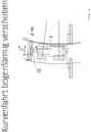
- the harvesting machine 1 comprises a headstock 2, by means of which the harvesting machine 1 can be attached to the front of the tractor 3.
- the headstock 2 can be attached to the tractor 3 in particular by means of a three-point linkage known per se comprising upper and lower links and can have corresponding linkage points 4 for the three-point linkage mentioned.
- the headstock 2 can be raised by the tractor 3 in order to raise the harvesting machine 1 and lowered in order to guide the harvesting machine 1 across the field during operation.
- a suspension 5 is provided on the headstock 2, through which a machine frame 6 is suspended and guided, wherein the said machine frame 6 can, for example, have a frame support 7 extending transversely to the direction of travel, on which the working unit 8 of the harvesting machine 1 is suspended or attached.
- the said working unit 8 can be a mower, for example, in the form of a row of mowing drums arranged next to one another or a cutter bar with rotating, drivable cutter disks.
- the said working unit 8 can have an overall elongated extension or contour and/or have a main axis 9, which can be defined by the working tools arranged next to one another, such as the cutting drums or cutter disks, and extends horizontally transversely to the direction of travel 10, cf. Figure 1 and Figure 2 .
- the suspension 5 is designed to be movable on multiple axes and, on the one hand, has a translational movement axis 11 for transversely displacing the working unit 8 along a movement path 13, which extends horizontally transversely to the direction of travel 10 and can have an arc-shaped contour, cf.
- the movement path 13 of the translational transverse displacement can be open to the rear with respect to the direction of travel 10 or can be convexly curved to the front in the direction of travel, for example forming at least approximately a circular path, the center of curvature of which can be located behind the tractor.
- the suspension 5 has a rotational degree of freedom for pivoting the working unit 8 about an upright pivot axis 12, as can be seen from a comparison of the Figures 3 to 5 clarified.
- the suspension 5 mentioned can be designed to be immobile or rigid in the vertical direction in order to guide the working unit 8 in a predetermined height position relative to the attachment block 2.
- the suspension 5 can also have a height mobility, preferably combined with a weight-relieving spring device in order to be able to guide the working unit 8 lightly over the ground.
- the suspension 5 can also have a horizontal pendulum axle 14 pointing approximately in the direction of travel 10 in order to enable rolling movements of the working unit 8, so that the working unit 8 can adapt to bumps with a transverse inclination by raising one lateral edge section and lowering the opposite other side section.
- the said suspension 5 can in particular project forward from the said attachment bracket 2 in the direction of travel 10 and push the working unit 8 in front of it, cf. for example Figure 3 .
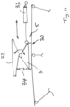
- the suspension 5 can advantageously comprise a linkage arrangement 15, which is provided between the attachment bracket 2 and the machine frame 6 or working unit 8 and can form a four-bar linkage with upright pivot axes.
- the linkage arrangement 15 can have two links 16 and 17, which can optionally be designed as double links, i.e. two links assigned to one another in pairs, or can also consist of a linkage frame, which can, for example, be constructed in a lattice-like manner from struts.
- the aforementioned links 16 and 17 of the linkage arrangement 15 advantageously have, on the one hand, linkage-side articulation points 18, 19, with which the links 16 and 17 can be connected at their rear ends, in particular directly to the linkage 2 or a console connected thereto.
- the links 16, 17 have linkage points 20, 21 on the work unit side, with which the links 16 and 17 can be connected at their front ends to the machine frame 6 or a pendulum support console 22 connected thereto, cf. Figure 1 .
- the links 16 and 17 are each pivotably mounted about upright pivot axes at their articulation points 18 to 21, so that the links 16, 17 form a four-bar linkage that can be pivoted in a horizontal plane.
- the upright pivot axes mentioned can be the only pivot axes of the links 16, 17, or the links 16, 17 mentioned can be firmly guided in the horizontal plane mentioned in order to be able to bear the weight of the working unit.
- an arrangement of the linkage arrangement 15 that can be moved up and down or can be swung up and down can also be provided, for example by means of a linkage console that can be pivotably mounted on the attachment block 2 about a horizontal transverse axis and can be pre-tensioned by a spring device in order to relieve the weight of the working unit.
- the links 16 and 17 can be arranged in a V-shape, spread apart from each other, in particular in their undeflected neutral position, cf.
- Figure 1 and Figure 3 The said spreading position of the four-bar linkage is defined by a different spacing of the articulation points 18 and 19 on the working unit side from one another on the one hand and the spacing of the articulation points 20, 21 on the working unit side from one another on the other hand.
- the articulation points 20, 21 on the working unit side can be further apart from each other than the articulation points 18, 19 on the headstock side.
- the linkage arrangement 15 thus forms a control device 23 in the form of a mechanical positive control for controlling the pivoting movement about the pivot axis 12 as a function of the transverse displacement along the movement path 13.
- At least one of the handlebars 16, 17 can be designed to be variable in length, for example telescopic, whereby an actuator for adjusting the length, for example in the form of a hydraulic cylinder, can be assigned to the variable-length handlebar.
- a hydraulic cylinder can form the handlebar itself or, in order to be able to bear higher suspension loads, can be assigned to a length-adjustable suspension support.
- the double arrow LV symbolizes the length adjustment of the handlebar 16.
- Such a length-adjustable steering rod 16 allows the tractor driver or an automated steering system to actively intervene in the radius of curvature or the kinematics if the mower alignment in relation to the tractor alignment has a negative impact on the mowing behavior.
- the mower alignment in relation to the tractor alignment can be corrected in the event of drifting when driving on sloping slopes.
- such a length-adjustable steering rod 16 can take on the function of a collision protection device or a shock absorber in the event of a collision in the outer area of the working unit. Both steering rods 16 and 17 can also be length-adjustable in the manner described.
- the suspension 5 can optionally also comprise a slide guide 30, which can have a slide 31 that is guided displaceably along the aforementioned movement path 13.
- the aforementioned movement path 13 can be designed in the form of a sliding guide.
- the said carriage 31 can carry a frame support 32 which can be pivotally mounted on the carriage 31 about the upright pivot axis 12 in order to be able to realize the pivoting movement of the working unit 8.
- a single actuator 35 may be sufficient, which may be hinged, for example, to the attachment bracket 2 on the one hand and to the pendulum support bracket 22 on the other hand, in order to be able to adjust the steering arrangement 15.
- the above-mentioned actuator 35 or the two actuators 33, 34 can be controlled by a control device, for example in the form of a job computer, in order to be able to adjust the working unit 8 when cornering and/or driving up a slope with drifting, wherein the above-mentioned control device 36 can have a manual input device for manually actuating the transverse adjustment and the pivoting.
- an automatic control module can also be provided which is connected to a sensor system 37 for detecting relevant operating parameters and controls the actuators depending on these, in particular depending on a steering angle signal which characterizes the steering angle of the tractor 3 and/or a slope inclination and/or drifting signal which characterizes the drifting or the slope inclination.
- the working unit 8 when cornering, can be moved transversely towards the inside of the curve and at the same time can also be swivelled in, in particular in such a way that the inside side section of the working unit 8 is swivelled backwards and/or the outside side section of the working unit is swivelled forwards.
- the working unit 8 in a right-hand bend, as Figure 8 shows, the working unit 8 is moved to the right and at the same time its right edge is pivoted backwards and its left edge is pivoted forwards, cf.
- Figure 8 compared to the Figures 6 and 7 .
- the coordination of the pivoting movement about the upright pivot axis 12 with the transverse displacement along the movement path 13 can be accomplished by the handlebar arrangement 15.
- the transverse adjustment along the movement path 13 is advantageously dimensioned such that the working unit 8 moves with its center over the movement path that takes the track center of the rear wheels.
- the proposed adjustment of the working unit 8 can also ensure the overlap with the inside side wing or rear wing of the harvesting machine 1.
- Figure 9 illustrates a sloped drive with the tractor 3 drifting without moving the front working unit 8, so that on the one hand the problem arises that the rear wheels of the tractor downhill drive over the crop that has been left standing and the side wings of the working unit downhill no longer have sufficient coverage.
- Figure 8 that the proposed transverse shift towards the inside of the curve in conjunction with pivoting of the working unit 8 to maintain the maximum working width can solve the aforementioned problem of the rear wheels driving over crops and also the problem of overlapping the rear side wings.
Landscapes
- Life Sciences & Earth Sciences (AREA)
- Environmental Sciences (AREA)
- Engineering & Computer Science (AREA)
- Mechanical Engineering (AREA)
- Soil Sciences (AREA)
- Agricultural Machines (AREA)
Applications Claiming Priority (1)
| Application Number | Priority Date | Filing Date | Title |
|---|---|---|---|
| DE102023110900.6A DE102023110900A1 (de) | 2023-04-27 | 2023-04-27 | Frontanbaubare Erntemaschine |
Publications (1)
| Publication Number | Publication Date |
|---|---|
| EP4454446A1 true EP4454446A1 (fr) | 2024-10-30 |
Family
ID=90366600
Family Applications (1)
| Application Number | Title | Priority Date | Filing Date |
|---|---|---|---|
| EP24164446.7A Pending EP4454446A1 (fr) | 2023-04-27 | 2024-03-19 | Moissonneuse à montage frontal |
Country Status (2)
| Country | Link |
|---|---|
| EP (1) | EP4454446A1 (fr) |
| DE (1) | DE102023110900A1 (fr) |
Citations (13)
| Publication number | Priority date | Publication date | Assignee | Title |
|---|---|---|---|---|
| DE2923821A1 (de) | 1978-06-10 | 1980-02-28 | Gudenaa Fab As | Grossflaechenrasenmaeher |
| NL8602334A (nl) * | 1986-09-15 | 1988-04-05 | Graaff S Import & Machinehande | Voertuig voorzien van voorwielbesturing en een pendelende maai-inrichting. |
| DE4314250C1 (de) | 1993-04-30 | 1994-07-21 | Fortschritt Erntemaschinen | Tragrahmen für ein Rotormähwerk großer Arbeitsbreite |
| DE4409113C1 (de) | 1994-03-17 | 1995-09-07 | Fortschritt Erntemaschinen | Lenkbewegliche Arbeitsaggregatekombination an einem frontgelenkten Trägerfahrzeug |
| NL1001172C2 (nl) * | 1995-09-11 | 1997-03-13 | Greenland Nieuw Vennep Bv | Inrichting voor het bewerken van landbouwgewas, zoals een maaimachine. |
| DE29816837U1 (de) * | 1998-09-19 | 1998-11-26 | Maschinenfabriken Bernard Krone Gmbh, 48480 Spelle | Arbeitsaggregatekombination an einem selbstfahrenden Trägerfahrzeug |
| DE10226551A1 (de) * | 2002-06-14 | 2003-12-24 | Wilhelm Kieninger | Lenkvorrichtung für Traktorfrontanbau-Geräte |
| WO2016041547A1 (fr) * | 2014-09-17 | 2016-03-24 | Jürgen Wagner | Véhicule tracteur et dispositif d'attelage pour équipement rapporté |
| DE102020127084A1 (de) | 2019-10-31 | 2021-05-06 | Deere & Company | Fahrzeugverbindungsleitsystem |
| WO2021113165A1 (fr) * | 2019-12-05 | 2021-06-10 | Mollick Peter J | Attelage en trois points avec actionneurs d'outil à fixer |
| IT201900025864A1 (it) | 2019-12-31 | 2021-07-01 | Orsi Group Srl | Macchina agricola. |
| EP3845048A1 (fr) | 2019-12-31 | 2021-07-07 | ORSI Group S.R.L. | Machine agricole |
| EP4162787A1 (fr) * | 2021-10-08 | 2023-04-12 | AGCO International GmbH | Commande d'outil et procédé correspondant |
-
2023
- 2023-04-27 DE DE102023110900.6A patent/DE102023110900A1/de active Pending
-
2024
- 2024-03-19 EP EP24164446.7A patent/EP4454446A1/fr active Pending
Patent Citations (13)
| Publication number | Priority date | Publication date | Assignee | Title |
|---|---|---|---|---|
| DE2923821A1 (de) | 1978-06-10 | 1980-02-28 | Gudenaa Fab As | Grossflaechenrasenmaeher |
| NL8602334A (nl) * | 1986-09-15 | 1988-04-05 | Graaff S Import & Machinehande | Voertuig voorzien van voorwielbesturing en een pendelende maai-inrichting. |
| DE4314250C1 (de) | 1993-04-30 | 1994-07-21 | Fortschritt Erntemaschinen | Tragrahmen für ein Rotormähwerk großer Arbeitsbreite |
| DE4409113C1 (de) | 1994-03-17 | 1995-09-07 | Fortschritt Erntemaschinen | Lenkbewegliche Arbeitsaggregatekombination an einem frontgelenkten Trägerfahrzeug |
| NL1001172C2 (nl) * | 1995-09-11 | 1997-03-13 | Greenland Nieuw Vennep Bv | Inrichting voor het bewerken van landbouwgewas, zoals een maaimachine. |
| DE29816837U1 (de) * | 1998-09-19 | 1998-11-26 | Maschinenfabriken Bernard Krone Gmbh, 48480 Spelle | Arbeitsaggregatekombination an einem selbstfahrenden Trägerfahrzeug |
| DE10226551A1 (de) * | 2002-06-14 | 2003-12-24 | Wilhelm Kieninger | Lenkvorrichtung für Traktorfrontanbau-Geräte |
| WO2016041547A1 (fr) * | 2014-09-17 | 2016-03-24 | Jürgen Wagner | Véhicule tracteur et dispositif d'attelage pour équipement rapporté |
| DE102020127084A1 (de) | 2019-10-31 | 2021-05-06 | Deere & Company | Fahrzeugverbindungsleitsystem |
| WO2021113165A1 (fr) * | 2019-12-05 | 2021-06-10 | Mollick Peter J | Attelage en trois points avec actionneurs d'outil à fixer |
| IT201900025864A1 (it) | 2019-12-31 | 2021-07-01 | Orsi Group Srl | Macchina agricola. |
| EP3845048A1 (fr) | 2019-12-31 | 2021-07-07 | ORSI Group S.R.L. | Machine agricole |
| EP4162787A1 (fr) * | 2021-10-08 | 2023-04-12 | AGCO International GmbH | Commande d'outil et procédé correspondant |
Also Published As
| Publication number | Publication date |
|---|---|
| DE102023110900A1 (de) | 2024-10-31 |
Similar Documents
| Publication | Publication Date | Title |
|---|---|---|
| EP1389413B1 (fr) | Articulation d'une tondeuse latérale et ses dispositifs auxiliaires avec une structure de support pour la fixation sur un tracteur ou un véhicule porteur | |
| DE2053073B2 (de) | Mähmaschine | |
| EP2499897B1 (fr) | Faneuse | |
| DE602004003137T2 (de) | Landwirtschaftliche mähmaschine | |
| EP0339231A2 (fr) | Machine agricole de fauchage et de fenaison | |
| DE3326297A1 (de) | Fahrzeug mit schwingungsbegrenzung | |
| EP0062734B1 (fr) | Charrue avec ligne de force de la coupe et point d'attache de traction réglable | |
| EP0807377A2 (fr) | Dispositif pour connecter un outil réglable en hauteur à un véhicule d'une position de travail dans une position de transport | |
| DE10321683B4 (de) | Pfosten-Freimäher und Verfahren zum Einsatz des Freimähers | |
| EP1093708A1 (fr) | Dispositif faucheur | |
| DE2808354C2 (fr) | ||
| EP2591653B2 (fr) | Machine de fenaison | |
| EP2710869B1 (fr) | Dispositif porte-outils frontal d'un véhicule de travail | |
| CH719870A2 (de) | Mähvorrichtung für ein Trägerfahrzeug. | |
| EP4454446A1 (fr) | Moissonneuse à montage frontal | |
| DE3835367C5 (de) | Vorrichtung für Mähwerke zur Bodenanpassung der Schneidwerke | |
| EP3620037A1 (fr) | Appareil de traitement du sol | |
| EP3058804B1 (fr) | Faneuse | |
| DE4228584C1 (de) | Selbstfahrende zweiachsige, mehrreihige Rübenerntemaschine | |
| DE3106929A1 (de) | Anbau-frontmaeher mit hin- und hergehenden maehmessern | |
| DE102014208071B4 (de) | Zwischen einer Betriebs- und einer Transportstellung verstellbares landwirtschaftliches Arbeitsgerät | |
| DE2750094C2 (fr) | ||
| DE20204398U1 (de) | Mähwerk | |
| DE3532114A1 (de) | Frontmaehwerk fuer schlepper | |
| DE102022131013A1 (de) | Landwirtschaftliche Erntemaschine |
Legal Events
| Date | Code | Title | Description |
|---|---|---|---|
| PUAI | Public reference made under article 153(3) epc to a published international application that has entered the european phase |
Free format text: ORIGINAL CODE: 0009012 |
|
| STAA | Information on the status of an ep patent application or granted ep patent |
Free format text: STATUS: THE APPLICATION HAS BEEN PUBLISHED |
|
| AK | Designated contracting states |
Kind code of ref document: A1 Designated state(s): AL AT BE BG CH CY CZ DE DK EE ES FI FR GB GR HR HU IE IS IT LI LT LU LV MC ME MK MT NL NO PL PT RO RS SE SI SK SM TR |
|
| STAA | Information on the status of an ep patent application or granted ep patent |
Free format text: STATUS: REQUEST FOR EXAMINATION WAS MADE |
|
| 17P | Request for examination filed |
Effective date: 20250429 |