EP3736155B1 - Hybridfahrzeug mit vierradantrieb mit einer elektrischen turbine versehenen brennkraftwärmemaschine und zugehöriges steuerungsverfahren - Google Patents
Hybridfahrzeug mit vierradantrieb mit einer elektrischen turbine versehenen brennkraftwärmemaschine und zugehöriges steuerungsverfahren Download PDFInfo
- Publication number
- EP3736155B1 EP3736155B1 EP20173757.4A EP20173757A EP3736155B1 EP 3736155 B1 EP3736155 B1 EP 3736155B1 EP 20173757 A EP20173757 A EP 20173757A EP 3736155 B1 EP3736155 B1 EP 3736155B1
- Authority
- EP
- European Patent Office
- Prior art keywords
- hybrid vehicle
- electric machine
- internal combustion
- electric power
- heat engine
- Prior art date
- Legal status (The legal status is an assumption and is not a legal conclusion. Google has not performed a legal analysis and makes no representation as to the accuracy of the status listed.)
- Active
Links
Images
Classifications
-
- F—MECHANICAL ENGINEERING; LIGHTING; HEATING; WEAPONS; BLASTING
- F02—COMBUSTION ENGINES; HOT-GAS OR COMBUSTION-PRODUCT ENGINE PLANTS
- F02B—INTERNAL-COMBUSTION PISTON ENGINES; COMBUSTION ENGINES IN GENERAL
- F02B37/00—Engines characterised by provision of pumps driven at least for part of the time by exhaust
- F02B37/04—Engines with exhaust drive and other drive of pumps, e.g. with exhaust-driven pump and mechanically-driven second pump
- F02B37/10—Engines with exhaust drive and other drive of pumps, e.g. with exhaust-driven pump and mechanically-driven second pump at least one pump being alternatively or simultaneously driven by exhaust and other drive, e.g. by pressurised fluid from a reservoir or an engine-driven pump
-
- F—MECHANICAL ENGINEERING; LIGHTING; HEATING; WEAPONS; BLASTING
- F02—COMBUSTION ENGINES; HOT-GAS OR COMBUSTION-PRODUCT ENGINE PLANTS
- F02D—CONTROLLING COMBUSTION ENGINES
- F02D13/00—Controlling the engine output power by varying inlet or exhaust valve operating characteristics, e.g. timing
- F02D13/02—Controlling the engine output power by varying inlet or exhaust valve operating characteristics, e.g. timing during engine operation
- F02D13/0242—Variable control of the exhaust valves only
- F02D13/0246—Variable control of the exhaust valves only changing valve lift or valve lift and timing
-
- F—MECHANICAL ENGINEERING; LIGHTING; HEATING; WEAPONS; BLASTING
- F02—COMBUSTION ENGINES; HOT-GAS OR COMBUSTION-PRODUCT ENGINE PLANTS
- F02D—CONTROLLING COMBUSTION ENGINES
- F02D13/00—Controlling the engine output power by varying inlet or exhaust valve operating characteristics, e.g. timing
- F02D13/02—Controlling the engine output power by varying inlet or exhaust valve operating characteristics, e.g. timing during engine operation
- F02D13/0242—Variable control of the exhaust valves only
- F02D13/0249—Variable control of the exhaust valves only changing the valve timing only
-
- B—PERFORMING OPERATIONS; TRANSPORTING
- B60—VEHICLES IN GENERAL
- B60K—ARRANGEMENT OR MOUNTING OF PROPULSION UNITS OR OF TRANSMISSIONS IN VEHICLES; ARRANGEMENT OR MOUNTING OF PLURAL DIVERSE PRIME-MOVERS IN VEHICLES; AUXILIARY DRIVES FOR VEHICLES; INSTRUMENTATION OR DASHBOARDS FOR VEHICLES; ARRANGEMENTS IN CONNECTION WITH COOLING, AIR INTAKE, GAS EXHAUST OR FUEL SUPPLY OF PROPULSION UNITS IN VEHICLES
- B60K6/00—Arrangement or mounting of plural diverse prime-movers for mutual or common propulsion, e.g. hybrid propulsion systems comprising electric motors and internal combustion engines
- B60K6/20—Arrangement or mounting of plural diverse prime-movers for mutual or common propulsion, e.g. hybrid propulsion systems comprising electric motors and internal combustion engines the prime-movers consisting of electric motors and internal combustion engines, e.g. HEVs
- B60K6/22—Arrangement or mounting of plural diverse prime-movers for mutual or common propulsion, e.g. hybrid propulsion systems comprising electric motors and internal combustion engines the prime-movers consisting of electric motors and internal combustion engines, e.g. HEVs characterised by apparatus, components or means specially adapted for HEVs
- B60K6/26—Arrangement or mounting of plural diverse prime-movers for mutual or common propulsion, e.g. hybrid propulsion systems comprising electric motors and internal combustion engines the prime-movers consisting of electric motors and internal combustion engines, e.g. HEVs characterised by apparatus, components or means specially adapted for HEVs characterised by the motors or the generators
-
- B—PERFORMING OPERATIONS; TRANSPORTING
- B60—VEHICLES IN GENERAL
- B60K—ARRANGEMENT OR MOUNTING OF PROPULSION UNITS OR OF TRANSMISSIONS IN VEHICLES; ARRANGEMENT OR MOUNTING OF PLURAL DIVERSE PRIME-MOVERS IN VEHICLES; AUXILIARY DRIVES FOR VEHICLES; INSTRUMENTATION OR DASHBOARDS FOR VEHICLES; ARRANGEMENTS IN CONNECTION WITH COOLING, AIR INTAKE, GAS EXHAUST OR FUEL SUPPLY OF PROPULSION UNITS IN VEHICLES
- B60K6/00—Arrangement or mounting of plural diverse prime-movers for mutual or common propulsion, e.g. hybrid propulsion systems comprising electric motors and internal combustion engines
- B60K6/20—Arrangement or mounting of plural diverse prime-movers for mutual or common propulsion, e.g. hybrid propulsion systems comprising electric motors and internal combustion engines the prime-movers consisting of electric motors and internal combustion engines, e.g. HEVs
- B60K6/50—Architecture of the driveline characterised by arrangement or kind of transmission units
- B60K6/52—Driving a plurality of drive axles, e.g. four-wheel drive
-
- B—PERFORMING OPERATIONS; TRANSPORTING
- B60—VEHICLES IN GENERAL
- B60W—CONJOINT CONTROL OF VEHICLE SUB-UNITS OF DIFFERENT TYPE OR DIFFERENT FUNCTION; CONTROL SYSTEMS SPECIALLY ADAPTED FOR HYBRID VEHICLES; ROAD VEHICLE DRIVE CONTROL SYSTEMS FOR PURPOSES NOT RELATED TO THE CONTROL OF A PARTICULAR SUB-UNIT
- B60W10/00—Conjoint control of vehicle sub-units of different type or different function
- B60W10/04—Conjoint control of vehicle sub-units of different type or different function including control of propulsion units
- B60W10/06—Conjoint control of vehicle sub-units of different type or different function including control of propulsion units including control of combustion engines
-
- B—PERFORMING OPERATIONS; TRANSPORTING
- B60—VEHICLES IN GENERAL
- B60W—CONJOINT CONTROL OF VEHICLE SUB-UNITS OF DIFFERENT TYPE OR DIFFERENT FUNCTION; CONTROL SYSTEMS SPECIALLY ADAPTED FOR HYBRID VEHICLES; ROAD VEHICLE DRIVE CONTROL SYSTEMS FOR PURPOSES NOT RELATED TO THE CONTROL OF A PARTICULAR SUB-UNIT
- B60W10/00—Conjoint control of vehicle sub-units of different type or different function
- B60W10/04—Conjoint control of vehicle sub-units of different type or different function including control of propulsion units
- B60W10/08—Conjoint control of vehicle sub-units of different type or different function including control of propulsion units including control of electric propulsion units, e.g. motors or generators
-
- B—PERFORMING OPERATIONS; TRANSPORTING
- B60—VEHICLES IN GENERAL
- B60W—CONJOINT CONTROL OF VEHICLE SUB-UNITS OF DIFFERENT TYPE OR DIFFERENT FUNCTION; CONTROL SYSTEMS SPECIALLY ADAPTED FOR HYBRID VEHICLES; ROAD VEHICLE DRIVE CONTROL SYSTEMS FOR PURPOSES NOT RELATED TO THE CONTROL OF A PARTICULAR SUB-UNIT
- B60W20/00—Control systems specially adapted for hybrid vehicles
- B60W20/10—Controlling the power contribution of each of the prime movers to meet required power demand
- B60W20/15—Control strategies specially adapted for achieving a particular effect
- B60W20/19—Control strategies specially adapted for achieving a particular effect for achieving enhanced acceleration
-
- B—PERFORMING OPERATIONS; TRANSPORTING
- B60—VEHICLES IN GENERAL
- B60W—CONJOINT CONTROL OF VEHICLE SUB-UNITS OF DIFFERENT TYPE OR DIFFERENT FUNCTION; CONTROL SYSTEMS SPECIALLY ADAPTED FOR HYBRID VEHICLES; ROAD VEHICLE DRIVE CONTROL SYSTEMS FOR PURPOSES NOT RELATED TO THE CONTROL OF A PARTICULAR SUB-UNIT
- B60W30/00—Purposes of road vehicle drive control systems not related to the control of a particular sub-unit, e.g. of systems using conjoint control of vehicle sub-units
- B60W30/18—Propelling the vehicle
- B60W30/188—Controlling power parameters of the driveline, e.g. determining the required power
-
- F—MECHANICAL ENGINEERING; LIGHTING; HEATING; WEAPONS; BLASTING
- F01—MACHINES OR ENGINES IN GENERAL; ENGINE PLANTS IN GENERAL; STEAM ENGINES
- F01N—GAS-FLOW SILENCERS OR EXHAUST APPARATUS FOR MACHINES OR ENGINES IN GENERAL; GAS-FLOW SILENCERS OR EXHAUST APPARATUS FOR INTERNAL-COMBUSTION ENGINES
- F01N5/00—Exhaust or silencing apparatus combined or associated with devices profiting by exhaust energy
- F01N5/04—Exhaust or silencing apparatus combined or associated with devices profiting by exhaust energy the devices using kinetic energy
-
- F—MECHANICAL ENGINEERING; LIGHTING; HEATING; WEAPONS; BLASTING
- F02—COMBUSTION ENGINES; HOT-GAS OR COMBUSTION-PRODUCT ENGINE PLANTS
- F02B—INTERNAL-COMBUSTION PISTON ENGINES; COMBUSTION ENGINES IN GENERAL
- F02B41/00—Engines characterised by special means for improving conversion of heat or pressure energy into mechanical power
- F02B41/02—Engines with prolonged expansion
- F02B41/10—Engines with prolonged expansion in exhaust turbines
-
- F—MECHANICAL ENGINEERING; LIGHTING; HEATING; WEAPONS; BLASTING
- F02—COMBUSTION ENGINES; HOT-GAS OR COMBUSTION-PRODUCT ENGINE PLANTS
- F02D—CONTROLLING COMBUSTION ENGINES
- F02D13/00—Controlling the engine output power by varying inlet or exhaust valve operating characteristics, e.g. timing
- F02D13/02—Controlling the engine output power by varying inlet or exhaust valve operating characteristics, e.g. timing during engine operation
- F02D13/0242—Variable control of the exhaust valves only
-
- F—MECHANICAL ENGINEERING; LIGHTING; HEATING; WEAPONS; BLASTING
- F02—COMBUSTION ENGINES; HOT-GAS OR COMBUSTION-PRODUCT ENGINE PLANTS
- F02D—CONTROLLING COMBUSTION ENGINES
- F02D13/00—Controlling the engine output power by varying inlet or exhaust valve operating characteristics, e.g. timing
- F02D13/02—Controlling the engine output power by varying inlet or exhaust valve operating characteristics, e.g. timing during engine operation
- F02D13/0276—Actuation of an additional valve for a special application, e.g. for decompression, exhaust gas recirculation or cylinder scavenging
-
- F—MECHANICAL ENGINEERING; LIGHTING; HEATING; WEAPONS; BLASTING
- F02—COMBUSTION ENGINES; HOT-GAS OR COMBUSTION-PRODUCT ENGINE PLANTS
- F02D—CONTROLLING COMBUSTION ENGINES
- F02D23/00—Controlling engines characterised by their being supercharged
-
- F—MECHANICAL ENGINEERING; LIGHTING; HEATING; WEAPONS; BLASTING
- F02—COMBUSTION ENGINES; HOT-GAS OR COMBUSTION-PRODUCT ENGINE PLANTS
- F02D—CONTROLLING COMBUSTION ENGINES
- F02D29/00—Controlling engines, such controlling being peculiar to the devices driven thereby, the devices being other than parts or accessories essential to engine operation, e.g. controlling of engines by signals external thereto
- F02D29/02—Controlling engines, such controlling being peculiar to the devices driven thereby, the devices being other than parts or accessories essential to engine operation, e.g. controlling of engines by signals external thereto peculiar to engines driving vehicles; peculiar to engines driving variable pitch propellers
-
- B—PERFORMING OPERATIONS; TRANSPORTING
- B60—VEHICLES IN GENERAL
- B60K—ARRANGEMENT OR MOUNTING OF PROPULSION UNITS OR OF TRANSMISSIONS IN VEHICLES; ARRANGEMENT OR MOUNTING OF PLURAL DIVERSE PRIME-MOVERS IN VEHICLES; AUXILIARY DRIVES FOR VEHICLES; INSTRUMENTATION OR DASHBOARDS FOR VEHICLES; ARRANGEMENTS IN CONNECTION WITH COOLING, AIR INTAKE, GAS EXHAUST OR FUEL SUPPLY OF PROPULSION UNITS IN VEHICLES
- B60K6/00—Arrangement or mounting of plural diverse prime-movers for mutual or common propulsion, e.g. hybrid propulsion systems comprising electric motors and internal combustion engines
- B60K6/20—Arrangement or mounting of plural diverse prime-movers for mutual or common propulsion, e.g. hybrid propulsion systems comprising electric motors and internal combustion engines the prime-movers consisting of electric motors and internal combustion engines, e.g. HEVs
-
- B—PERFORMING OPERATIONS; TRANSPORTING
- B60—VEHICLES IN GENERAL
- B60Y—INDEXING SCHEME RELATING TO ASPECTS CROSS-CUTTING VEHICLE TECHNOLOGY
- B60Y2400/00—Special features of vehicle units
- B60Y2400/43—Engines
- B60Y2400/435—Supercharger or turbochargers
-
- B—PERFORMING OPERATIONS; TRANSPORTING
- B60—VEHICLES IN GENERAL
- B60Y—INDEXING SCHEME RELATING TO ASPECTS CROSS-CUTTING VEHICLE TECHNOLOGY
- B60Y2400/00—Special features of vehicle units
- B60Y2400/43—Engines
- B60Y2400/44—Exhaust turbines driving generators
-
- F—MECHANICAL ENGINEERING; LIGHTING; HEATING; WEAPONS; BLASTING
- F01—MACHINES OR ENGINES IN GENERAL; ENGINE PLANTS IN GENERAL; STEAM ENGINES
- F01D—NON-POSITIVE DISPLACEMENT MACHINES OR ENGINES, e.g. STEAM TURBINES
- F01D15/00—Adaptations of machines or engines for special use; Combinations of engines with devices driven thereby
- F01D15/10—Adaptations for driving, or combinations with, electric generators
-
- F—MECHANICAL ENGINEERING; LIGHTING; HEATING; WEAPONS; BLASTING
- F02—COMBUSTION ENGINES; HOT-GAS OR COMBUSTION-PRODUCT ENGINE PLANTS
- F02B—INTERNAL-COMBUSTION PISTON ENGINES; COMBUSTION ENGINES IN GENERAL
- F02B33/00—Engines characterised by provision of pumps for charging or scavenging
- F02B33/32—Engines with pumps other than of reciprocating-piston type
- F02B33/34—Engines with pumps other than of reciprocating-piston type with rotary pumps
-
- F—MECHANICAL ENGINEERING; LIGHTING; HEATING; WEAPONS; BLASTING
- F02—COMBUSTION ENGINES; HOT-GAS OR COMBUSTION-PRODUCT ENGINE PLANTS
- F02B—INTERNAL-COMBUSTION PISTON ENGINES; COMBUSTION ENGINES IN GENERAL
- F02B39/00—Component parts, details, or accessories relating to, driven charging or scavenging pumps, not provided for in groups F02B33/00 - F02B37/00
- F02B39/02—Drives of pumps; Varying pump drive gear ratio
- F02B39/08—Non-mechanical drives, e.g. fluid drives having variable gear ratio
- F02B39/10—Non-mechanical drives, e.g. fluid drives having variable gear ratio electric
-
- F—MECHANICAL ENGINEERING; LIGHTING; HEATING; WEAPONS; BLASTING
- F02—COMBUSTION ENGINES; HOT-GAS OR COMBUSTION-PRODUCT ENGINE PLANTS
- F02B—INTERNAL-COMBUSTION PISTON ENGINES; COMBUSTION ENGINES IN GENERAL
- F02B63/00—Adaptations of engines for driving pumps, hand-held tools or electric generators; Portable combinations of engines with engine-driven devices
- F02B63/04—Adaptations of engines for driving pumps, hand-held tools or electric generators; Portable combinations of engines with engine-driven devices for electric generators
- F02B63/042—Rotating electric generators
-
- F—MECHANICAL ENGINEERING; LIGHTING; HEATING; WEAPONS; BLASTING
- F02—COMBUSTION ENGINES; HOT-GAS OR COMBUSTION-PRODUCT ENGINE PLANTS
- F02D—CONTROLLING COMBUSTION ENGINES
- F02D41/00—Electrical control of supply of combustible mixture or its constituents
- F02D41/0002—Controlling intake air
- F02D2041/001—Controlling intake air for engines with variable valve actuation
-
- F—MECHANICAL ENGINEERING; LIGHTING; HEATING; WEAPONS; BLASTING
- F02—COMBUSTION ENGINES; HOT-GAS OR COMBUSTION-PRODUCT ENGINE PLANTS
- F02D—CONTROLLING COMBUSTION ENGINES
- F02D41/00—Electrical control of supply of combustible mixture or its constituents
- F02D41/0002—Controlling intake air
- F02D41/0007—Controlling intake air for control of turbo-charged or super-charged engines
-
- Y—GENERAL TAGGING OF NEW TECHNOLOGICAL DEVELOPMENTS; GENERAL TAGGING OF CROSS-SECTIONAL TECHNOLOGIES SPANNING OVER SEVERAL SECTIONS OF THE IPC; TECHNICAL SUBJECTS COVERED BY FORMER USPC CROSS-REFERENCE ART COLLECTIONS [XRACs] AND DIGESTS
- Y02—TECHNOLOGIES OR APPLICATIONS FOR MITIGATION OR ADAPTATION AGAINST CLIMATE CHANGE
- Y02T—CLIMATE CHANGE MITIGATION TECHNOLOGIES RELATED TO TRANSPORTATION
- Y02T10/00—Road transport of goods or passengers
- Y02T10/60—Other road transportation technologies with climate change mitigation effect
- Y02T10/62—Hybrid vehicles
Definitions
- the invention relates to a four-wheel drive hybrid vehicle comprising an internal combustion heat engine provided with an electrified turbine and to a corresponding control method.
- a hybrid vehicle comprises an internal combustion heat engine, which transmits a torque to the drive wheels by means of a drivetrain provided with a transmission, and at least one main electric machine, which is electrically connected to a power storage system and is mechanically connected to the drive wheels.
- the internal combustion heat engine is connected to a first pair of drive wheels (namely, the rear or front drive wheels), whereas the main electric machine s connected to a second pair of drive wheels (namely, to the front or rear drive wheels) and there is no direct mechanical connection between the internal combustion heat engine and the main electric machine; therefore, the internal combustion heat engine and the main electric machine can exchange torque (namely, energy) with one another only through the four drive wheels and the road surface.
- auxiliary electric machine which is mechanically connected to the internal combustion heat engine and is exclusively used as electric generator to generate electrical energy to be subsequently used by the main electric machine (and to be generally at least partly stored, at first, in the power storage system).
- the internal combustion heat engine can be provided with a turbocharger supercharging system, which is capable of increasing the power developed by the internal combustion heat engine using the enthalpy of the exhaust gases to compress the air sucked in by the internal combustion heat engine and, hence, increase the volumetric efficiency of the intake.
- a turbocharger supercharging system traditionally comprises a turbocharger provided with a turbine, which is arranged along an exhaust duct so as to rotate, at a high speed, due to the thrust of the exhaust gases expelled by the internal combustion heat engine, and with a compressor, which is caused to rotate by the turbine and is arranged along the air feeding duct to compress the air taken in by the internal combustion heat engine.
- electrified turbochargers comprising at least one reversible electric machine, which is fitted to the shaft shared by the compressor and by the turbine so as to operate as a motor increasing the rotation speed of the compressor (thus, eliminating the so-called turbo lag) or so as to operate as a generator exploiting the enthalpy of the exhaust gases to generate electrical energy.
- the compressor can mechanically be completely independent of the turbine and there can be a first electric machine, which always and only works as motor and causes the rotation of the compressor, and a second electric machine, which always and only works as generator and is caused to rotate by the turbine.
- the object of the invention is to provide a four-wheel drive hybrid vehicle comprising an internal combustion heat engine provided with an electrified turbine and a corresponding control method, said hybrid vehicle being as simple and as light as possible, though still offering high performances.
- a four-wheel drive hybrid vehicle comprising an internal combustion heat engine provided with an electrified turbine and a corresponding control method according to the appended claims.
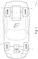
- number 1 indicates, as a whole, a hybrid vehicle (or hybrid-drive vehicle) provided with two front drive wheels 2, which receive the torque from an electric machine 3, and with two rear drive wheel 4, which receive the torque from an internal combustion heat engine 5, which is completely separate from and independent of the electric machine 3 (namely, there is no direct mechanical connection between the internal combustion heat engine 5 and the electric machine 3).
- the electric machine 3 is connected to the two front drive wheels 2 by means of a drivetrain system (which is known and, hence, is not shown) provided with a front differential; similarly, the internal combustion heat engine 5 is connected to the two rear drive wheels 4 by means of a drivetrain system (which is known and, hence, is not shown) provided with a transmission and with a rear differential,
- the electric machine 3 is reversible (namely, it can work both as an electric motor, thus absorbing electrical energy and generating a mechanical torque, and as an electric generator, thus absorbing mechanical energy and generating electrical energy) and is controlled by a control device 6 (in particular, an electronic AC/DC power converter, namely an "inverter” ) , which is connected to a power storage system 7 provided with chemical batteries.
- a control device 6 in particular, an electronic AC/DC power converter, namely an "inverter”
- the control device 6 is a two-way device and comprises a direct current side, which is connected to the storage system 7, and a three-phase alternating current side, which is connected to the electric machine 3.
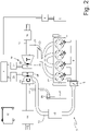
- the internal combustion heat engine 5 comprises four cylinders 8, each connected to an intake manifold 9 by means of two intake valves 10 and to an exhaust manifold 11 by means of two exhaust valves 12.
- the valves 10 and 12 are operated by respective cams, which are caused to rotate by the drive shaft.
- the phases of the valves 10 and 12 do not normally coincide with the corresponding strokes of the piston established by the idealized cycle; since the accelerations imposed on the valves 10 and 12 cannot exceed certain limits concerning the resistance of the material used, the beginning of the movement of the valves 10 and 12 is advanced by 5°-15° so as to obtain a regular opening, without instantaneous jerks.
- the movement of the valves 10 and 12 is minimum relative to the rotation of the cam and, then, the lift of the valves 10 and 12 increases proportionally to the rotation angle, until it reaches the maximum value in proximity to half stroke of the piston.
- the exhaust valves 12 start their opening with an advance ranging from 35° to 65° relative to the BDC; in this last part of the stroke, the useful work produced by the expansion of the gases would anyway be very small, so that it is convenient to advance the exhaust stroke at the expense of the expansion stroke.
- the movement of the exhaust valves 12 takes place similarly to the one of the intake valves 10; the exhaust valves 12, however, close with a delay ranging from 2° to 30° relative to the TDC (top dead centre), so as to exploit the inertia of the gases, which, due to the speed gained, keep flowing out even though they are not pushed by the piston any longer.
- the intake manifold 4 receives fresh air (i.e. air coming from the outside) through an intake duct 13, which is provided with an air filter 14 and is regulated by a throttle valve 15. Along the intake duct 13 there is an intercooler 16, which fulfils the function of cooling the air taken in.
- the exhaust manifold 11 is connected to an exhaust duct 17, which feeds the exhaust gases produced by the combustion to an exhaust system, which releases the gases produced by the combustion into the atmosphere and normally comprises at least one catalytic converter 18 and at least one silencer (not shown) arranged downstream of the catalytic converter 18.
- the internal combustion heat engine 5 comprises a supercharging system comprising, in turn, a turbocharger 19 provided with a turbine 20, which is arranged along the exhaust duct 17 so as to rotate at a high speed due to the action of the exhaust gases expelled from the cylinders 8, and a compressor 21, which is arranged along the intake duct 13 to increase the pressure of the air fed by the feeding duct 13 ad is mechanically independent of the turbine 20 (namely, it does not have any mechanical connection to the turbine 20).
- a supercharging system comprising, in turn, a turbocharger 19 provided with a turbine 20, which is arranged along the exhaust duct 17 so as to rotate at a high speed due to the action of the exhaust gases expelled from the cylinders 8, and a compressor 21, which is arranged along the intake duct 13 to increase the pressure of the air fed by the feeding duct 13 ad is mechanically independent of the turbine 20 (namely, it does not have any mechanical connection to the turbine 20).
- bypass duct 22 which is connected in parallel to the turbine 20 so as to have its ends connected upstream and downstream of the turbine 20; along the bypass duct 22 there is a wastegate valve 23, which is designed to adjust the flow rate of the exhaust gases flowing through the bypass duct 22 and is controlled by an actuator (which is not shown).
- bypass duct 24 which is connected in parallel to the compressor 21 so as to have its ends connected upstream and downstream of the compressor 21; along the bypass duct 25 there is a blowoff valve 25, which is designed to adjust the flow rate of the exhaust gases flowing through the bypass duct 24 and is controlled by an actuator (which is not shown).
- the turbine 20 and the compressor 21 are not mechanically connected to one another and, therefore, they can be placed in different areas of the internal combustion heat engine 5.
- the turbine 20 is fitted to an electric generator 26, which is caused to rotate by the turbine 20 so as to generate electrical energy; the electric generator 26 is electrically connected to a control device 27 (in particular, an electronic AC/DC power converter), which, in turn, is connected to the storage system 7.
- the compressor 21 is fitted to an electric motor 28, which causes the compressor 21 to rotate; the electric motor 28 is electrically connected to a control device 29 (in particular, an electronic AC/DC power converter), which, in turn, is connected to the storage system 7.
- the road vehicle 1 is controlled by a control unit 30, which controls the operation of all the components of the road vehicle 1, such as the electric machine 3 and the internal combustion heat engine 5.
- the control unit 30 uses the electric machine 3 as a motor, when a torque needs to be delivered to the front wheels 2 (for example, because of a need for a low-speed running in a merely electric mode or because the rear wheels 4 skid and cannot discharge all the torque requested by the driver to the ground), and uses the electric machine 3 as a generator, when the road vehicle 1 is slowing down.
- the control unit 30 controls the electric motor 28, which causes the rotation of the compressor 21, and the electric generator 26, which is caused to rotate by the turbine 20, in a completely autonomous manner from one another.
- the control unit 30 controls the electric motor 28, which causes the compressor 21 to rotate, with the sole purpose of optimizing the intake of the cylinders 8 based on the requested performances (namely, in terms of torque and power to be delivered by the internal combustion heat engine 5);
- the control unit 30 controls the electric generator 26, which is caused to rotate by the turbine 20, with the sole purpose of optimizing the generation of electric energy, namely maximizing the electric power without jeopardizing the operation of the internal combustion heat engine 5.
- the electrical energy on board the road vehicle 1 is generated by the sole electric generator 26; namely, aside from the electric machine 3, which can occasionally and briefly operate as generator, on board the road vehicle 1 the only means suited to generate electrical energy is the electric generator 26, which is caused to rotate by the turbine 20. In other words, on board the road vehicle 1 the only means suited to continuously generate electrical energy is the electric generator 26, which is caused to rotate by the turbine 20. Therefore, the road vehicle 1 completely lacks an electric machine which receives the motion from the drive shaft of the internal combustion heat engine 5 to generate electrical energy.
- control unit 30 cyclically determines an electric power P des to be necessarily generated in order to deal with the electrical energy consumptions (of the electric machine 3, of the electric motor 28 and of other electric utilities, such as lights, control members, infotainment system%) and, if necessary, in order to charge the storage system 7; furthermore, in use, the control unit 30 cyclically determines an electric power P eff generated by the electric generator 26.
- control unit 30 controls the opening advance of the exhaust valves 12 depending on the difference between the electric power P des to be necessarily generated and the electric power P eff generated by the electric generator 26:
- the internal combustion heat engine 5 must be provided with a (known) system for the variation of the timing of the cams controlling (at least) the exhaust valves 12.
- the minimum value of the opening advance of the exhaust valves 12 is an ideal value, which maximizes the energy efficiency of the internal combustion heat engine 5 completely independently of the electrical energy generation needs; on the other hand, the maximum value of the opening advance of the exhaust valves 12 is a limit value, which avoids excessively jeopardizing the energy efficiency of the internal combustion heat engine 5.
- the minimum and maximum values of the opening advance of the exhaust valves 12 could be fixed or could change depending on the engine point of the internal combustion engine 5.
- the control unit 30 controls the internal combustion heat engine 5 so as to maximize the energy efficiency (namely, so as to to use the minimum value of the opening advance of the exhaust valves 12, which maximizes the energy efficiency of the internal combustion heat engine 5); obviously, if the electric power P eff generated by the electric generator 26 exceeds the electric power P des to be necessarily generated, the excess electric power is stored in the storage system 7 or is used to increase the use of the electric machine 3 operating as motor.
- the control unit 30 controls the internal combustion heat engine 5 damaging (worsening) the energy efficiency in order to increase the mechanical power generated by the turbine 20 (namely, absorbed by the electric generator 26); in other words, in order to increase the enthalpy of the exhaust gases, the control unit 30 increases the opening advance of the exhaust valves 12 so as to cause the exhaust gases to flow out of the exhaust valves 12 and towards the exhaust manifold 11 at a higher pressure (thus, not using this higher pressure to push the pistons and, hence, to generate mechanical energy inside the internal combustion heat engine 5) .
- the turbine 20 is mechanically independent of the compressor 21 and, therefore, there are, for the supercharging system, two distinct electric machines: the electric generator 26, which is caused to rotate by the turbine 20, and the electric motor 28, which causes the rotation of the compressor 21.
- the turbine 20 and the compressor 21 are mounted on the same shaft (hence, they always rotate together at the same speed) and the supercharging system comprises one single reversible electric machine, which is mounted on the same shaft as the turbine 20 and the compressor 21 and can work as a generator (operated by the turbine 20) and, if necessary, also as a motor (for short instants, so as eliminate the turbocharger response delay); in other words, in this embodiment, the single reversible electric machine of the supercharging system almost always acts as generator (operated by the turbine 20) and occasionally and for short instants as motor so as eliminate the turbocharger response delay).
- the compressor 20 (with the relative electric motor 28), which increases the intake pressure; according to a different embodiment which is not shown herein, the compressor 20 (with the relative electric motor 28) is not present and, therefore, the internal combustion heat engine 5 is not supercharged (namely, it is an aspirated engine).
- the road vehicle 1 described above has numerous advantages.
- the road vehicle 1 described above is capable of generating all the electric power needed in any possible operating condition, namely it is capable of increasing or decreasing, in any possible operating condition and according to the needs, the electric power P eff generated by the electric generator 26.
- the road vehicle 1 described above is not provided with an electric generator which is (directly or indirectly) caused to rotate by the drive shaft of the internal combustion heat engine 5, with a consequent reduction of costs, dimensions and weight.
- the road vehicle 1 described above is simple to be manufactured, as it only requires the use of known components available in the market.
Landscapes
- Engineering & Computer Science (AREA)
- Chemical & Material Sciences (AREA)
- Combustion & Propulsion (AREA)
- Mechanical Engineering (AREA)
- General Engineering & Computer Science (AREA)
- Transportation (AREA)
- Automation & Control Theory (AREA)
- Supercharger (AREA)
- Hybrid Electric Vehicles (AREA)
Claims (10)
- Hybridfahrzeug (1) mit vier Antriebsrädern (2, 4), das aufweist:einen Verbrennungsmotor (5), der die Bewegung zu einem ersten Paar Antriebsräder (4) überträgt und mindestens einen Zylinder (8) hat, der mit mindestens einem Einlassventil (10) und mit einem Auslassventil (12) versehen ist;eine Turbine (20), die so gestaltet ist, dass sie durch die Abgase gedreht wird, die aus dem Zylinder (8) durch das Auslassventil (12) strömen;eine erste elektrische Maschine (26), die so gestaltet ist, dass sie durch die Turbine (20) gedreht wird, um Elektroenergie zu erzeugen;eine zweite elektrische Maschine (3), die die Bewegung zu einem zweiten Paar Antriebsräder (2) überträgt und keine direkte mechanische Verbindung mit dem Verbrennungsmotor (5) hat; undeine Steuereinheit (30);wobei das Hybridfahrzeug (1) dadurch gekennzeichnet ist, dass:das Hybridfahrzeug (1) keinerlei elektrische Maschine hat, die die Bewegung von einer Welle des Verbrennungsmotors (5) empfängt;die Steuereinheit (30) so konfiguriert ist, dass sie zyklisch bestimmt: eine notwendigerweise zu erzeugende elektrische Leistung (Pdes) und eine durch die erste elektrische Maschine (26) erzeugte elektrische Leistung (Peff); unddie Steuereinheit (30) so konfiguriert ist, dass sie eine Öffnungs-Vorverstellung des Auslassventils (12) in Abhängigkeit von der Differenz zwischen der durch die erste elektrische Maschine (26) erzeugten elektrischen Leistung (Peff) und der notwendigerweise zu erzeugenden elektrischen Leistung (Pdes) einstellt.
- Hybridfahrzeug (1) nach Anspruch 1, wobei die Steuereinheit (30) so konfiguriert ist, dass sie die Öffnungs-Vorverstellung des Auslassventils (12) erhöht, wenn die notwendigerweise zu erzeugende elektrische Leistung (Pdes) größer als die durch die erste elektrische Maschine (26) erzeugte elektrische Leistung (Peff) ist.
- Hybridfahrzeug (1) nach Anspruch 2, wobei die Steuereinheit (30) so konfiguriert ist, dass sie die Öffnungs-Vorverstellung des Auslassventils (12) nicht über einen Maximalwert hinaus erhöht.
- Hybridfahrzeug (1) nach Anspruch 1, 2 oder 3, wobei die Steuereinheit (30) so konfiguriert ist, dass sie die Öffnungs-Vorverstellung des Auslassventils (12) verringert, wenn die notwendigerweise zu erzeugende elektrische Leistung (Pdes) größer als die durch die erste elektrische Maschine (26) erzeugte elektrische Leistung (Peff) ist.
- Hybridfahrzeug (1) nach Anspruch 4, wobei die Steuereinheit (30) so konfiguriert ist, dass sie die Öffnungs-Vorverstellung des Auslassventils (12) nicht über einen Minimalwert hinaus verringert.
- Hybridfahrzeug (1) nach Anspruch 5, wobei der Minimalwert ein Idealwert ist, der es ermöglicht, den energetischen Wirkungsgrad des Verbrennungsmotors (5) komplett unabhängig von den Elektroenergieerzeugungsbedürfnissen zu maximieren.
- Hybridfahrzeug (1) nach einem der Ansprüche 1 bis 6, wobei die Steuereinheit (30) so konfiguriert ist, dass sie die Öffnungs-Vorverstellung des Auslassventils (12) konstant hält, wenn die notwendigerweise zu erzeugende elektrische Leistung (Pdes) gleich der durch die erste elektrische Maschine (26) erzeugten elektrischen Leistung (Peff) ist.
- Hybridfahrzeug (1) nach einem der Ansprüche 1 bis 7 und mit einem Kompressor (21), der so gestaltet ist, dass er einen Einlassdruck des Zylinders (8) erhöht, und direkt durch die Turbine (20) drehen gelassen wird, mit der er mechanisch verbunden ist.
- Hybridfahrzeug (1) nach einem der Ansprüche 1 bis 7, das aufweist:einen Kompressor (21), der so gestaltet ist, dass er einen Einlassdruck des Zylinders (8) erhöht, und mechanisch unabhängig von der Turbine (20) ist; undeine dritte elektrische Maschine (28), die so gestaltet ist, dass sie den Kompressor (21) drehen lässt.
- Verfahren zur Steuerung eines Hybridfahrzeugs (1) mit vier Antriebsrädern (2, 4); wobei das Hybridfahrzeug (1) aufweist:einen Verbrennungsmotor (5), der die Bewegung zu einem ersten Paar Antriebsräder (4) überträgt und mindestens einen Zylinder (8) hat, der mit mindestens einem Einlassventil (10) und mit einem Auslassventil (12) versehen ist;eine Turbine (20), die so gestaltet ist, dass sie durch die Abgase gedreht wird, die aus dem Zylinder (8) durch das Auslassventil (12) strömen;eine erste elektrische Maschine (26), die so gestaltet ist, dass sie durch die Turbine (20) gedreht wird, um Elektroenergie zu erzeugen;eine zweite elektrische Maschine (3), die die Bewegung zu einem zweiten Paar Antriebsräder (2) überträgt und keine direkte mechanische Verbindung mit dem Verbrennungsmotor (5) hat; undeine Steuereinheit (30);wobei das Steuerverfahren dadurch gekennzeichnet ist, dass:das Hybridfahrzeug (1) keinerlei elektrische Maschine hat, die die Bewegung von einer Welle des Verbrennungsmotors (5) empfängt;die Steuereinheit (30) zyklisch bestimmt: eine notwendigerweise zu erzeugende elektrische Leistung (Pdes) und eine durch die erste elektrische Maschine (26) erzeugte elektrische Leistung (Peff); und die Steuereinheit (30) eine Öffnungs-Vorverstellung des Auslassventils (12) in Abhängigkeit von der Differenz zwischen der durch die erste elektrische Maschine (26) erzeugten elektrischen Leistung (Peff) und der notwendigerweise zu erzeugenden elektrischen Leistung (Pdes) einstellt.
Applications Claiming Priority (1)
| Application Number | Priority Date | Filing Date | Title |
|---|---|---|---|
| IT102019000006696A IT201900006696A1 (it) | 2019-05-09 | 2019-05-09 | Veicolo ibrido a quattro ruote motrici comprendente un motore termico a combustione interna provvisto di una turbina elettrificata e corrispondente metodo di controllo |
Publications (2)
| Publication Number | Publication Date |
|---|---|
| EP3736155A1 EP3736155A1 (de) | 2020-11-11 |
| EP3736155B1 true EP3736155B1 (de) | 2022-08-17 |
Family
ID=67660685
Family Applications (1)
| Application Number | Title | Priority Date | Filing Date |
|---|---|---|---|
| EP20173757.4A Active EP3736155B1 (de) | 2019-05-09 | 2020-05-08 | Hybridfahrzeug mit vierradantrieb mit einer elektrischen turbine versehenen brennkraftwärmemaschine und zugehöriges steuerungsverfahren |
Country Status (4)
| Country | Link |
|---|---|
| US (1) | US11498405B2 (de) |
| EP (1) | EP3736155B1 (de) |
| CN (1) | CN111911294B (de) |
| IT (1) | IT201900006696A1 (de) |
Families Citing this family (4)
| Publication number | Priority date | Publication date | Assignee | Title |
|---|---|---|---|---|
| CN112848870B (zh) * | 2021-01-29 | 2022-04-26 | 金陵科技学院 | 进气及废气涡轮增压发电混合动力系统及控制方法 |
| JP2022123697A (ja) * | 2021-02-12 | 2022-08-24 | 株式会社Subaru | 過給システム |
| EP4141226B1 (de) | 2021-08-27 | 2025-01-29 | António Cameira Eiras, Unipessoal Lda | Verbessertes fahrzeug mit abgasenergierückgewinnung |
| EP4328428B1 (de) * | 2022-08-25 | 2025-06-11 | FERRARI S.p.A. | Kraftfahrzeug mit einem verbrennungsmotor aufweisend eine seitliche abgasauslassöffnung |
Family Cites Families (10)
| Publication number | Priority date | Publication date | Assignee | Title |
|---|---|---|---|---|
| GB0400808D0 (en) * | 2004-01-14 | 2004-02-18 | Lotus Car | A turbocharged internal combustion engine |
| US7076954B1 (en) | 2005-03-31 | 2006-07-18 | Caterpillar Inc. | Turbocharger system |
| US7891185B2 (en) * | 2007-08-17 | 2011-02-22 | Deere & Company | Turbo-generator control with variable valve actuation |
| JP5167326B2 (ja) * | 2010-11-05 | 2013-03-21 | 三菱重工業株式会社 | エンジン排気エネルギー回収装置 |
| US20120285166A1 (en) * | 2011-05-11 | 2012-11-15 | GM Global Technology Operations LLC | Hybrid powertrain system |
| CN106604841A (zh) * | 2014-08-22 | 2017-04-26 | 博格华纳公司 | 用于通过道路型混合动力车辆的多模式离合器 |
| US9624850B2 (en) * | 2014-11-10 | 2017-04-18 | Ford Global Technologies, Llc | Systems and methods for control of turbine-generator via exhaust valve timing and duration modulation in a split exhaust engine system |
| US9896991B2 (en) * | 2015-03-31 | 2018-02-20 | Ford Global Technologies, Llc | Exhaust-gas-turbocharged internal combustion engine having at least two turbines and switchable outlet openings, and method for operating an internal combustion engine of said type |
| US10082111B2 (en) * | 2015-08-27 | 2018-09-25 | GM Global Technology Operations LLC | Turbocharging system with electric motor(s) |
| US10145320B1 (en) * | 2017-08-31 | 2018-12-04 | Ford Global Technologies, Llc | Methods and systems for boost and EGR control |
-
2019
- 2019-05-09 IT IT102019000006696A patent/IT201900006696A1/it unknown
-
2020
- 2020-05-06 US US16/867,663 patent/US11498405B2/en active Active
- 2020-05-08 CN CN202010382027.7A patent/CN111911294B/zh active Active
- 2020-05-08 EP EP20173757.4A patent/EP3736155B1/de active Active
Also Published As
| Publication number | Publication date |
|---|---|
| IT201900006696A1 (it) | 2020-11-09 |
| US20200353808A1 (en) | 2020-11-12 |
| CN111911294A (zh) | 2020-11-10 |
| EP3736155A1 (de) | 2020-11-11 |
| US11498405B2 (en) | 2022-11-15 |
| CN111911294B (zh) | 2023-10-24 |
| BR102020009050A2 (pt) | 2020-11-17 |
Similar Documents
| Publication | Publication Date | Title |
|---|---|---|
| EP3736155B1 (de) | Hybridfahrzeug mit vierradantrieb mit einer elektrischen turbine versehenen brennkraftwärmemaschine und zugehöriges steuerungsverfahren | |
| CN101424212B (zh) | 包括旋转分离的进气压缩机和排气涡轮的内燃机压缩系统 | |
| US8997488B2 (en) | Turbocharged reciprocating piston engine having a connected pressure tank for bridging turbo lag, and method for operating said engine | |
| US7152705B2 (en) | Dual engine electric drive system | |
| EP2715088B1 (de) | Aufgeladene turbocompound-motorvorrichtung, insbesondere für industriefahrzeuge | |
| EP1801386A1 (de) | Anordnung mit einer Brennkraftmaschine | |
| US20100139266A1 (en) | Systems for Recovering the Unused Energy of Exhaust Gas of an Internal Combustion Engine and Corresponding Methods | |
| JPH10238354A (ja) | ハイブリッド過給エンジン | |
| JP2023022854A (ja) | ハイブリッド車両 | |
| US10697359B2 (en) | Supercharged internal combustion engine | |
| US20150292399A1 (en) | Altering Engine Combustion Cycle Using Electric Motor-Driven Exhaust and Intake Air Pumps | |
| CN101092893A (zh) | 高增压米勒循环发动机及其控制方法 | |
| US20130233289A1 (en) | Supercharged Internal Combustion Engine | |
| JP7028329B2 (ja) | 車両の制御方法及び車両の制御装置 | |
| WO2010127446A1 (en) | Air compression method and apparatus | |
| JP2002038962A (ja) | ターボチャージャ付き内燃機関の制御装置 | |
| CN116292174A (zh) | 用于车载压缩机的方法和系统 | |
| US10190547B2 (en) | Partial forced induction system | |
| JP5490053B2 (ja) | 車両の制御装置 | |
| JP3941010B2 (ja) | 過給装置およびエンジンの過給方法 | |
| JP2004044433A (ja) | ハイブリッド車両の制御装置及び方法、並びにハイブリッド車両 | |
| JP2010275955A (ja) | 車両の制御装置 | |
| WO2013118308A1 (en) | Turbocharger excess power recovery device for internal combustion engine | |
| CN202727997U (zh) | 直线isg电机和直线发动机结合的增程器 | |
| JP7718163B2 (ja) | ハイブリッド車両の制御方法および制御装置 |
Legal Events
| Date | Code | Title | Description |
|---|---|---|---|
| PUAI | Public reference made under article 153(3) epc to a published international application that has entered the european phase |
Free format text: ORIGINAL CODE: 0009012 |
|
| STAA | Information on the status of an ep patent application or granted ep patent |
Free format text: STATUS: THE APPLICATION HAS BEEN PUBLISHED |
|
| AK | Designated contracting states |
Kind code of ref document: A1 Designated state(s): AL AT BE BG CH CY CZ DE DK EE ES FI FR GB GR HR HU IE IS IT LI LT LU LV MC MK MT NL NO PL PT RO RS SE SI SK SM TR |
|
| AX | Request for extension of the european patent |
Extension state: BA ME |
|
| STAA | Information on the status of an ep patent application or granted ep patent |
Free format text: STATUS: REQUEST FOR EXAMINATION WAS MADE |
|
| 17P | Request for examination filed |
Effective date: 20210322 |
|
| RIC1 | Information provided on ipc code assigned before grant |
Ipc: F02D 41/00 20060101ALN20210811BHEP Ipc: F02B 37/10 20060101ALN20210811BHEP Ipc: F02B 33/34 20060101ALN20210811BHEP Ipc: B60W 30/188 20120101ALI20210811BHEP Ipc: B60W 20/19 20160101ALI20210811BHEP Ipc: B60W 20/15 20160101ALI20210811BHEP Ipc: B60W 10/08 20060101ALI20210811BHEP Ipc: B60W 10/06 20060101ALI20210811BHEP Ipc: F02D 13/00 20060101ALI20210811BHEP Ipc: F01N 5/04 20060101ALI20210811BHEP Ipc: F02N 15/04 20060101ALI20210811BHEP Ipc: F02D 13/02 20060101ALI20210811BHEP Ipc: F02B 39/10 20060101ALI20210811BHEP Ipc: B60K 6/52 20071001AFI20210811BHEP |
|
| RIC1 | Information provided on ipc code assigned before grant |
Ipc: F02D 41/00 20060101ALN20210920BHEP Ipc: F02B 37/10 20060101ALN20210920BHEP Ipc: F02B 33/34 20060101ALN20210920BHEP Ipc: B60W 30/188 20120101ALI20210920BHEP Ipc: B60W 20/19 20160101ALI20210920BHEP Ipc: B60W 20/15 20160101ALI20210920BHEP Ipc: B60W 10/08 20060101ALI20210920BHEP Ipc: B60W 10/06 20060101ALI20210920BHEP Ipc: F02D 13/00 20060101ALI20210920BHEP Ipc: F01N 5/04 20060101ALI20210920BHEP Ipc: F02N 15/04 20060101ALI20210920BHEP Ipc: F02D 13/02 20060101ALI20210920BHEP Ipc: F02B 39/10 20060101ALI20210920BHEP Ipc: B60K 6/52 20071001AFI20210920BHEP |
|
| GRAP | Despatch of communication of intention to grant a patent |
Free format text: ORIGINAL CODE: EPIDOSNIGR1 |
|
| STAA | Information on the status of an ep patent application or granted ep patent |
Free format text: STATUS: GRANT OF PATENT IS INTENDED |
|
| INTG | Intention to grant announced |
Effective date: 20220309 |
|
| GRAS | Grant fee paid |
Free format text: ORIGINAL CODE: EPIDOSNIGR3 |
|
| GRAA | (expected) grant |
Free format text: ORIGINAL CODE: 0009210 |
|
| STAA | Information on the status of an ep patent application or granted ep patent |
Free format text: STATUS: THE PATENT HAS BEEN GRANTED |
|
| AK | Designated contracting states |
Kind code of ref document: B1 Designated state(s): AL AT BE BG CH CY CZ DE DK EE ES FI FR GB GR HR HU IE IS IT LI LT LU LV MC MK MT NL NO PL PT RO RS SE SI SK SM TR |
|
| REG | Reference to a national code |
Ref country code: CH Ref legal event code: EP |
|
| REG | Reference to a national code |
Ref country code: DE Ref legal event code: R096 Ref document number: 602020004530 Country of ref document: DE |
|
| REG | Reference to a national code |
Ref country code: IE Ref legal event code: FG4D |
|
| REG | Reference to a national code |
Ref country code: AT Ref legal event code: REF Ref document number: 1511954 Country of ref document: AT Kind code of ref document: T Effective date: 20220915 |
|
| REG | Reference to a national code |
Ref country code: NL Ref legal event code: MP Effective date: 20220817 |
|
| REG | Reference to a national code |
Ref country code: LT Ref legal event code: MG9D |
|
| PG25 | Lapsed in a contracting state [announced via postgrant information from national office to epo] |
Ref country code: SE Free format text: LAPSE BECAUSE OF FAILURE TO SUBMIT A TRANSLATION OF THE DESCRIPTION OR TO PAY THE FEE WITHIN THE PRESCRIBED TIME-LIMIT Effective date: 20220817 Ref country code: RS Free format text: LAPSE BECAUSE OF FAILURE TO SUBMIT A TRANSLATION OF THE DESCRIPTION OR TO PAY THE FEE WITHIN THE PRESCRIBED TIME-LIMIT Effective date: 20220817 Ref country code: PT Free format text: LAPSE BECAUSE OF FAILURE TO SUBMIT A TRANSLATION OF THE DESCRIPTION OR TO PAY THE FEE WITHIN THE PRESCRIBED TIME-LIMIT Effective date: 20221219 Ref country code: NO Free format text: LAPSE BECAUSE OF FAILURE TO SUBMIT A TRANSLATION OF THE DESCRIPTION OR TO PAY THE FEE WITHIN THE PRESCRIBED TIME-LIMIT Effective date: 20221117 Ref country code: NL Free format text: LAPSE BECAUSE OF FAILURE TO SUBMIT A TRANSLATION OF THE DESCRIPTION OR TO PAY THE FEE WITHIN THE PRESCRIBED TIME-LIMIT Effective date: 20220817 Ref country code: LV Free format text: LAPSE BECAUSE OF FAILURE TO SUBMIT A TRANSLATION OF THE DESCRIPTION OR TO PAY THE FEE WITHIN THE PRESCRIBED TIME-LIMIT Effective date: 20220817 Ref country code: LT Free format text: LAPSE BECAUSE OF FAILURE TO SUBMIT A TRANSLATION OF THE DESCRIPTION OR TO PAY THE FEE WITHIN THE PRESCRIBED TIME-LIMIT Effective date: 20220817 Ref country code: FI Free format text: LAPSE BECAUSE OF FAILURE TO SUBMIT A TRANSLATION OF THE DESCRIPTION OR TO PAY THE FEE WITHIN THE PRESCRIBED TIME-LIMIT Effective date: 20220817 |
|
| REG | Reference to a national code |
Ref country code: AT Ref legal event code: MK05 Ref document number: 1511954 Country of ref document: AT Kind code of ref document: T Effective date: 20220817 |
|
| PG25 | Lapsed in a contracting state [announced via postgrant information from national office to epo] |
Ref country code: PL Free format text: LAPSE BECAUSE OF FAILURE TO SUBMIT A TRANSLATION OF THE DESCRIPTION OR TO PAY THE FEE WITHIN THE PRESCRIBED TIME-LIMIT Effective date: 20220817 Ref country code: IS Free format text: LAPSE BECAUSE OF FAILURE TO SUBMIT A TRANSLATION OF THE DESCRIPTION OR TO PAY THE FEE WITHIN THE PRESCRIBED TIME-LIMIT Effective date: 20221217 Ref country code: HR Free format text: LAPSE BECAUSE OF FAILURE TO SUBMIT A TRANSLATION OF THE DESCRIPTION OR TO PAY THE FEE WITHIN THE PRESCRIBED TIME-LIMIT Effective date: 20220817 Ref country code: GR Free format text: LAPSE BECAUSE OF FAILURE TO SUBMIT A TRANSLATION OF THE DESCRIPTION OR TO PAY THE FEE WITHIN THE PRESCRIBED TIME-LIMIT Effective date: 20221118 |
|
| PG25 | Lapsed in a contracting state [announced via postgrant information from national office to epo] |
Ref country code: SM Free format text: LAPSE BECAUSE OF FAILURE TO SUBMIT A TRANSLATION OF THE DESCRIPTION OR TO PAY THE FEE WITHIN THE PRESCRIBED TIME-LIMIT Effective date: 20220817 Ref country code: RO Free format text: LAPSE BECAUSE OF FAILURE TO SUBMIT A TRANSLATION OF THE DESCRIPTION OR TO PAY THE FEE WITHIN THE PRESCRIBED TIME-LIMIT Effective date: 20220817 Ref country code: ES Free format text: LAPSE BECAUSE OF FAILURE TO SUBMIT A TRANSLATION OF THE DESCRIPTION OR TO PAY THE FEE WITHIN THE PRESCRIBED TIME-LIMIT Effective date: 20220817 Ref country code: DK Free format text: LAPSE BECAUSE OF FAILURE TO SUBMIT A TRANSLATION OF THE DESCRIPTION OR TO PAY THE FEE WITHIN THE PRESCRIBED TIME-LIMIT Effective date: 20220817 Ref country code: CZ Free format text: LAPSE BECAUSE OF FAILURE TO SUBMIT A TRANSLATION OF THE DESCRIPTION OR TO PAY THE FEE WITHIN THE PRESCRIBED TIME-LIMIT Effective date: 20220817 Ref country code: AT Free format text: LAPSE BECAUSE OF FAILURE TO SUBMIT A TRANSLATION OF THE DESCRIPTION OR TO PAY THE FEE WITHIN THE PRESCRIBED TIME-LIMIT Effective date: 20220817 |
|
| REG | Reference to a national code |
Ref country code: DE Ref legal event code: R097 Ref document number: 602020004530 Country of ref document: DE |
|
| PG25 | Lapsed in a contracting state [announced via postgrant information from national office to epo] |
Ref country code: SK Free format text: LAPSE BECAUSE OF FAILURE TO SUBMIT A TRANSLATION OF THE DESCRIPTION OR TO PAY THE FEE WITHIN THE PRESCRIBED TIME-LIMIT Effective date: 20220817 Ref country code: EE Free format text: LAPSE BECAUSE OF FAILURE TO SUBMIT A TRANSLATION OF THE DESCRIPTION OR TO PAY THE FEE WITHIN THE PRESCRIBED TIME-LIMIT Effective date: 20220817 |
|
| PLBE | No opposition filed within time limit |
Free format text: ORIGINAL CODE: 0009261 |
|
| STAA | Information on the status of an ep patent application or granted ep patent |
Free format text: STATUS: NO OPPOSITION FILED WITHIN TIME LIMIT |
|
| PG25 | Lapsed in a contracting state [announced via postgrant information from national office to epo] |
Ref country code: AL Free format text: LAPSE BECAUSE OF FAILURE TO SUBMIT A TRANSLATION OF THE DESCRIPTION OR TO PAY THE FEE WITHIN THE PRESCRIBED TIME-LIMIT Effective date: 20220817 |
|
| P01 | Opt-out of the competence of the unified patent court (upc) registered |
Effective date: 20230525 |
|
| 26N | No opposition filed |
Effective date: 20230519 |
|
| PG25 | Lapsed in a contracting state [announced via postgrant information from national office to epo] |
Ref country code: SI Free format text: LAPSE BECAUSE OF FAILURE TO SUBMIT A TRANSLATION OF THE DESCRIPTION OR TO PAY THE FEE WITHIN THE PRESCRIBED TIME-LIMIT Effective date: 20220817 |
|
| REG | Reference to a national code |
Ref country code: CH Ref legal event code: PL |
|
| PG25 | Lapsed in a contracting state [announced via postgrant information from national office to epo] |
Ref country code: MC Free format text: LAPSE BECAUSE OF FAILURE TO SUBMIT A TRANSLATION OF THE DESCRIPTION OR TO PAY THE FEE WITHIN THE PRESCRIBED TIME-LIMIT Effective date: 20220817 |
|
| REG | Reference to a national code |
Ref country code: BE Ref legal event code: MM Effective date: 20230531 |
|
| PG25 | Lapsed in a contracting state [announced via postgrant information from national office to epo] |
Ref country code: MC Free format text: LAPSE BECAUSE OF FAILURE TO SUBMIT A TRANSLATION OF THE DESCRIPTION OR TO PAY THE FEE WITHIN THE PRESCRIBED TIME-LIMIT Effective date: 20220817 Ref country code: LU Free format text: LAPSE BECAUSE OF NON-PAYMENT OF DUE FEES Effective date: 20230508 Ref country code: LI Free format text: LAPSE BECAUSE OF NON-PAYMENT OF DUE FEES Effective date: 20230531 Ref country code: CH Free format text: LAPSE BECAUSE OF NON-PAYMENT OF DUE FEES Effective date: 20230531 |
|
| REG | Reference to a national code |
Ref country code: IE Ref legal event code: MM4A |
|
| PG25 | Lapsed in a contracting state [announced via postgrant information from national office to epo] |
Ref country code: IE Free format text: LAPSE BECAUSE OF NON-PAYMENT OF DUE FEES Effective date: 20230508 |
|
| PG25 | Lapsed in a contracting state [announced via postgrant information from national office to epo] |
Ref country code: IE Free format text: LAPSE BECAUSE OF NON-PAYMENT OF DUE FEES Effective date: 20230508 |
|
| PG25 | Lapsed in a contracting state [announced via postgrant information from national office to epo] |
Ref country code: BE Free format text: LAPSE BECAUSE OF NON-PAYMENT OF DUE FEES Effective date: 20230531 |
|
| PG25 | Lapsed in a contracting state [announced via postgrant information from national office to epo] |
Ref country code: BG Free format text: LAPSE BECAUSE OF FAILURE TO SUBMIT A TRANSLATION OF THE DESCRIPTION OR TO PAY THE FEE WITHIN THE PRESCRIBED TIME-LIMIT Effective date: 20220817 |
|
| PG25 | Lapsed in a contracting state [announced via postgrant information from national office to epo] |
Ref country code: BG Free format text: LAPSE BECAUSE OF FAILURE TO SUBMIT A TRANSLATION OF THE DESCRIPTION OR TO PAY THE FEE WITHIN THE PRESCRIBED TIME-LIMIT Effective date: 20220817 |
|
| PGFP | Annual fee paid to national office [announced via postgrant information from national office to epo] |
Ref country code: DE Payment date: 20250528 Year of fee payment: 6 |
|
| PGFP | Annual fee paid to national office [announced via postgrant information from national office to epo] |
Ref country code: IT Payment date: 20250509 Year of fee payment: 6 |
|
| PGFP | Annual fee paid to national office [announced via postgrant information from national office to epo] |
Ref country code: FR Payment date: 20250526 Year of fee payment: 6 |
|
| PG25 | Lapsed in a contracting state [announced via postgrant information from national office to epo] |
Ref country code: CY Free format text: LAPSE BECAUSE OF FAILURE TO SUBMIT A TRANSLATION OF THE DESCRIPTION OR TO PAY THE FEE WITHIN THE PRESCRIBED TIME-LIMIT; INVALID AB INITIO Effective date: 20200508 |
|
| PG25 | Lapsed in a contracting state [announced via postgrant information from national office to epo] |
Ref country code: HU Free format text: LAPSE BECAUSE OF FAILURE TO SUBMIT A TRANSLATION OF THE DESCRIPTION OR TO PAY THE FEE WITHIN THE PRESCRIBED TIME-LIMIT; INVALID AB INITIO Effective date: 20200508 |
|
| PG25 | Lapsed in a contracting state [announced via postgrant information from national office to epo] |
Ref country code: TR Free format text: LAPSE BECAUSE OF FAILURE TO SUBMIT A TRANSLATION OF THE DESCRIPTION OR TO PAY THE FEE WITHIN THE PRESCRIBED TIME-LIMIT Effective date: 20220817 |
|
| PGFP | Annual fee paid to national office [announced via postgrant information from national office to epo] |
Ref country code: GB Payment date: 20260304 Year of fee payment: 7 |