EP3736169B1 - Station et système de recharge rapide de véhicule électrique (ev) - Google Patents
Station et système de recharge rapide de véhicule électrique (ev) Download PDFInfo
- Publication number
- EP3736169B1 EP3736169B1 EP20182706.0A EP20182706A EP3736169B1 EP 3736169 B1 EP3736169 B1 EP 3736169B1 EP 20182706 A EP20182706 A EP 20182706A EP 3736169 B1 EP3736169 B1 EP 3736169B1
- Authority
- EP
- European Patent Office
- Prior art keywords
- power
- converter
- station according
- charging
- station
- Prior art date
- Legal status (The legal status is an assumption and is not a legal conclusion. Google has not performed a legal analysis and makes no representation as to the accuracy of the status listed.)
- Active
Links
Images

Classifications
-
- H—ELECTRICITY
- H02—GENERATION; CONVERSION OR DISTRIBUTION OF ELECTRIC POWER
- H02J—ELECTRIC POWER NETWORKS; CIRCUIT ARRANGEMENTS OR SYSTEMS FOR SUPPLYING OR DISTRIBUTING ELECTRIC POWER; SYSTEMS FOR STORING ELECTRIC ENERGY
- H02J7/00—Circuit arrangements for charging or discharging batteries or for supplying loads from batteries
- H02J7/02—Circuit arrangements for charging or discharging batteries or for supplying loads from batteries for charging batteries from AC mains by converters
-
- B—PERFORMING OPERATIONS; TRANSPORTING
- B60—VEHICLES IN GENERAL
- B60L—PROPULSION OF ELECTRICALLY-PROPELLED VEHICLES; SUPPLYING ELECTRIC POWER FOR AUXILIARY EQUIPMENT OF ELECTRICALLY-PROPELLED VEHICLES; ELECTRODYNAMIC BRAKE SYSTEMS FOR VEHICLES IN GENERAL; MAGNETIC SUSPENSION OR LEVITATION FOR VEHICLES; MONITORING OPERATING VARIABLES OF ELECTRICALLY-PROPELLED VEHICLES; ELECTRIC SAFETY DEVICES FOR ELECTRICALLY-PROPELLED VEHICLES
- B60L53/00—Methods of charging batteries, specially adapted for electric vehicles; Charging stations or on-board charging equipment therefor; Exchange of energy storage elements in electric vehicles
- B60L53/10—Methods of charging batteries, specially adapted for electric vehicles; Charging stations or on-board charging equipment therefor; Exchange of energy storage elements in electric vehicles characterised by the energy transfer between the charging station and the vehicle
- B60L53/11—DC charging controlled by the charging station, e.g. mode 4
-
- B—PERFORMING OPERATIONS; TRANSPORTING
- B60—VEHICLES IN GENERAL
- B60L—PROPULSION OF ELECTRICALLY-PROPELLED VEHICLES; SUPPLYING ELECTRIC POWER FOR AUXILIARY EQUIPMENT OF ELECTRICALLY-PROPELLED VEHICLES; ELECTRODYNAMIC BRAKE SYSTEMS FOR VEHICLES IN GENERAL; MAGNETIC SUSPENSION OR LEVITATION FOR VEHICLES; MONITORING OPERATING VARIABLES OF ELECTRICALLY-PROPELLED VEHICLES; ELECTRIC SAFETY DEVICES FOR ELECTRICALLY-PROPELLED VEHICLES
- B60L50/00—Electric propulsion with power supplied within the vehicle
- B60L50/10—Electric propulsion with power supplied within the vehicle using propulsion power supplied by engine-driven generators, e.g. generators driven by combustion engines
- B60L50/12—Electric propulsion with power supplied within the vehicle using propulsion power supplied by engine-driven generators, e.g. generators driven by combustion engines using AC generators and DC motors
-
- B—PERFORMING OPERATIONS; TRANSPORTING
- B60—VEHICLES IN GENERAL
- B60L—PROPULSION OF ELECTRICALLY-PROPELLED VEHICLES; SUPPLYING ELECTRIC POWER FOR AUXILIARY EQUIPMENT OF ELECTRICALLY-PROPELLED VEHICLES; ELECTRODYNAMIC BRAKE SYSTEMS FOR VEHICLES IN GENERAL; MAGNETIC SUSPENSION OR LEVITATION FOR VEHICLES; MONITORING OPERATING VARIABLES OF ELECTRICALLY-PROPELLED VEHICLES; ELECTRIC SAFETY DEVICES FOR ELECTRICALLY-PROPELLED VEHICLES
- B60L53/00—Methods of charging batteries, specially adapted for electric vehicles; Charging stations or on-board charging equipment therefor; Exchange of energy storage elements in electric vehicles
- B60L53/30—Constructional details of charging stations
- B60L53/31—Charging columns specially adapted for electric vehicles
-
- B—PERFORMING OPERATIONS; TRANSPORTING
- B60—VEHICLES IN GENERAL
- B60L—PROPULSION OF ELECTRICALLY-PROPELLED VEHICLES; SUPPLYING ELECTRIC POWER FOR AUXILIARY EQUIPMENT OF ELECTRICALLY-PROPELLED VEHICLES; ELECTRODYNAMIC BRAKE SYSTEMS FOR VEHICLES IN GENERAL; MAGNETIC SUSPENSION OR LEVITATION FOR VEHICLES; MONITORING OPERATING VARIABLES OF ELECTRICALLY-PROPELLED VEHICLES; ELECTRIC SAFETY DEVICES FOR ELECTRICALLY-PROPELLED VEHICLES
- B60L53/00—Methods of charging batteries, specially adapted for electric vehicles; Charging stations or on-board charging equipment therefor; Exchange of energy storage elements in electric vehicles
- B60L53/50—Charging stations characterised by energy-storage or power-generation means
- B60L53/53—Batteries
-
- B—PERFORMING OPERATIONS; TRANSPORTING
- B60—VEHICLES IN GENERAL
- B60L—PROPULSION OF ELECTRICALLY-PROPELLED VEHICLES; SUPPLYING ELECTRIC POWER FOR AUXILIARY EQUIPMENT OF ELECTRICALLY-PROPELLED VEHICLES; ELECTRODYNAMIC BRAKE SYSTEMS FOR VEHICLES IN GENERAL; MAGNETIC SUSPENSION OR LEVITATION FOR VEHICLES; MONITORING OPERATING VARIABLES OF ELECTRICALLY-PROPELLED VEHICLES; ELECTRIC SAFETY DEVICES FOR ELECTRICALLY-PROPELLED VEHICLES
- B60L53/00—Methods of charging batteries, specially adapted for electric vehicles; Charging stations or on-board charging equipment therefor; Exchange of energy storage elements in electric vehicles
- B60L53/60—Monitoring or controlling charging stations
- B60L53/67—Controlling two or more charging stations
-
- H—ELECTRICITY
- H02—GENERATION; CONVERSION OR DISTRIBUTION OF ELECTRIC POWER
- H02J—ELECTRIC POWER NETWORKS; CIRCUIT ARRANGEMENTS OR SYSTEMS FOR SUPPLYING OR DISTRIBUTING ELECTRIC POWER; SYSTEMS FOR STORING ELECTRIC ENERGY
- H02J1/00—Circuit arrangements for DC mains or DC distribution networks
-
- H—ELECTRICITY
- H02—GENERATION; CONVERSION OR DISTRIBUTION OF ELECTRIC POWER
- H02J—ELECTRIC POWER NETWORKS; CIRCUIT ARRANGEMENTS OR SYSTEMS FOR SUPPLYING OR DISTRIBUTING ELECTRIC POWER; SYSTEMS FOR STORING ELECTRIC ENERGY
- H02J3/00—Circuit arrangements for AC mains or AC distribution networks
- H02J3/28—Arrangements for balancing of the load in networks by storage of energy
- H02J3/32—Arrangements for balancing of the load in networks by storage of energy using batteries or super capacitors with converting means
- H02J3/322—Arrangements for balancing of the load in networks by storage of energy using batteries or super capacitors with converting means the battery being on-board an electric or hybrid vehicle, e.g. vehicle to grid arrangements [V2G], power aggregation, use of the battery for network load balancing, coordinated or cooperative battery charging
-
- H—ELECTRICITY
- H02—GENERATION; CONVERSION OR DISTRIBUTION OF ELECTRIC POWER
- H02J—ELECTRIC POWER NETWORKS; CIRCUIT ARRANGEMENTS OR SYSTEMS FOR SUPPLYING OR DISTRIBUTING ELECTRIC POWER; SYSTEMS FOR STORING ELECTRIC ENERGY
- H02J7/00—Circuit arrangements for charging or discharging batteries or for supplying loads from batteries
- H02J7/50—Circuit arrangements for charging or discharging batteries or for supplying loads from batteries acting upon multiple batteries simultaneously or sequentially
-
- H—ELECTRICITY
- H02—GENERATION; CONVERSION OR DISTRIBUTION OF ELECTRIC POWER
- H02J—ELECTRIC POWER NETWORKS; CIRCUIT ARRANGEMENTS OR SYSTEMS FOR SUPPLYING OR DISTRIBUTING ELECTRIC POWER; SYSTEMS FOR STORING ELECTRIC ENERGY
- H02J7/00—Circuit arrangements for charging or discharging batteries or for supplying loads from batteries
- H02J7/50—Circuit arrangements for charging or discharging batteries or for supplying loads from batteries acting upon multiple batteries simultaneously or sequentially
- H02J7/575—Parallel/serial switching of connection of batteries to charge or load circuit
-
- H—ELECTRICITY
- H02—GENERATION; CONVERSION OR DISTRIBUTION OF ELECTRIC POWER
- H02J—ELECTRIC POWER NETWORKS; CIRCUIT ARRANGEMENTS OR SYSTEMS FOR SUPPLYING OR DISTRIBUTING ELECTRIC POWER; SYSTEMS FOR STORING ELECTRIC ENERGY
- H02J7/00—Circuit arrangements for charging or discharging batteries or for supplying loads from batteries
- H02J7/70—Circuit arrangements for charging or discharging batteries or for supplying loads from batteries characterised by the mechanical construction
-
- B—PERFORMING OPERATIONS; TRANSPORTING
- B60—VEHICLES IN GENERAL
- B60L—PROPULSION OF ELECTRICALLY-PROPELLED VEHICLES; SUPPLYING ELECTRIC POWER FOR AUXILIARY EQUIPMENT OF ELECTRICALLY-PROPELLED VEHICLES; ELECTRODYNAMIC BRAKE SYSTEMS FOR VEHICLES IN GENERAL; MAGNETIC SUSPENSION OR LEVITATION FOR VEHICLES; MONITORING OPERATING VARIABLES OF ELECTRICALLY-PROPELLED VEHICLES; ELECTRIC SAFETY DEVICES FOR ELECTRICALLY-PROPELLED VEHICLES
- B60L2210/00—Converter types
- B60L2210/10—DC to DC converters
-
- B—PERFORMING OPERATIONS; TRANSPORTING
- B60—VEHICLES IN GENERAL
- B60L—PROPULSION OF ELECTRICALLY-PROPELLED VEHICLES; SUPPLYING ELECTRIC POWER FOR AUXILIARY EQUIPMENT OF ELECTRICALLY-PROPELLED VEHICLES; ELECTRODYNAMIC BRAKE SYSTEMS FOR VEHICLES IN GENERAL; MAGNETIC SUSPENSION OR LEVITATION FOR VEHICLES; MONITORING OPERATING VARIABLES OF ELECTRICALLY-PROPELLED VEHICLES; ELECTRIC SAFETY DEVICES FOR ELECTRICALLY-PROPELLED VEHICLES
- B60L2210/00—Converter types
- B60L2210/30—AC to DC converters
-
- H—ELECTRICITY
- H02—GENERATION; CONVERSION OR DISTRIBUTION OF ELECTRIC POWER
- H02J—ELECTRIC POWER NETWORKS; CIRCUIT ARRANGEMENTS OR SYSTEMS FOR SUPPLYING OR DISTRIBUTING ELECTRIC POWER; SYSTEMS FOR STORING ELECTRIC ENERGY
- H02J2105/00—Networks for supplying or distributing electric power characterised by their spatial reach or by the load
- H02J2105/30—Networks for supplying or distributing electric power characterised by their spatial reach or by the load the load networks being external to vehicles, i.e. exchanging power with vehicles
- H02J2105/33—Networks for supplying or distributing electric power characterised by their spatial reach or by the load the load networks being external to vehicles, i.e. exchanging power with vehicles exchanging power with road vehicles
- H02J2105/37—Networks for supplying or distributing electric power characterised by their spatial reach or by the load the load networks being external to vehicles, i.e. exchanging power with vehicles exchanging power with road vehicles exchanging power with electric vehicles [EV] or with hybrid electric vehicles [HEV]
-
- H—ELECTRICITY
- H02—GENERATION; CONVERSION OR DISTRIBUTION OF ELECTRIC POWER
- H02J—ELECTRIC POWER NETWORKS; CIRCUIT ARRANGEMENTS OR SYSTEMS FOR SUPPLYING OR DISTRIBUTING ELECTRIC POWER; SYSTEMS FOR STORING ELECTRIC ENERGY
- H02J2207/00—Details of circuit arrangements for charging or discharging batteries or supplying loads from batteries
- H02J2207/20—Charging or discharging characterised by the power electronics converter
-
- Y—GENERAL TAGGING OF NEW TECHNOLOGICAL DEVELOPMENTS; GENERAL TAGGING OF CROSS-SECTIONAL TECHNOLOGIES SPANNING OVER SEVERAL SECTIONS OF THE IPC; TECHNICAL SUBJECTS COVERED BY FORMER USPC CROSS-REFERENCE ART COLLECTIONS [XRACs] AND DIGESTS
- Y02—TECHNOLOGIES OR APPLICATIONS FOR MITIGATION OR ADAPTATION AGAINST CLIMATE CHANGE
- Y02T—CLIMATE CHANGE MITIGATION TECHNOLOGIES RELATED TO TRANSPORTATION
- Y02T10/00—Road transport of goods or passengers
- Y02T10/60—Other road transportation technologies with climate change mitigation effect
- Y02T10/70—Energy storage systems for electromobility, e.g. batteries
-
- Y—GENERAL TAGGING OF NEW TECHNOLOGICAL DEVELOPMENTS; GENERAL TAGGING OF CROSS-SECTIONAL TECHNOLOGIES SPANNING OVER SEVERAL SECTIONS OF THE IPC; TECHNICAL SUBJECTS COVERED BY FORMER USPC CROSS-REFERENCE ART COLLECTIONS [XRACs] AND DIGESTS
- Y02—TECHNOLOGIES OR APPLICATIONS FOR MITIGATION OR ADAPTATION AGAINST CLIMATE CHANGE
- Y02T—CLIMATE CHANGE MITIGATION TECHNOLOGIES RELATED TO TRANSPORTATION
- Y02T10/00—Road transport of goods or passengers
- Y02T10/60—Other road transportation technologies with climate change mitigation effect
- Y02T10/7072—Electromobility specific charging systems or methods for batteries, ultracapacitors, supercapacitors or double-layer capacitors
-
- Y—GENERAL TAGGING OF NEW TECHNOLOGICAL DEVELOPMENTS; GENERAL TAGGING OF CROSS-SECTIONAL TECHNOLOGIES SPANNING OVER SEVERAL SECTIONS OF THE IPC; TECHNICAL SUBJECTS COVERED BY FORMER USPC CROSS-REFERENCE ART COLLECTIONS [XRACs] AND DIGESTS
- Y02—TECHNOLOGIES OR APPLICATIONS FOR MITIGATION OR ADAPTATION AGAINST CLIMATE CHANGE
- Y02T—CLIMATE CHANGE MITIGATION TECHNOLOGIES RELATED TO TRANSPORTATION
- Y02T10/00—Road transport of goods or passengers
- Y02T10/60—Other road transportation technologies with climate change mitigation effect
- Y02T10/72—Electric energy management in electromobility
-
- Y—GENERAL TAGGING OF NEW TECHNOLOGICAL DEVELOPMENTS; GENERAL TAGGING OF CROSS-SECTIONAL TECHNOLOGIES SPANNING OVER SEVERAL SECTIONS OF THE IPC; TECHNICAL SUBJECTS COVERED BY FORMER USPC CROSS-REFERENCE ART COLLECTIONS [XRACs] AND DIGESTS
- Y02—TECHNOLOGIES OR APPLICATIONS FOR MITIGATION OR ADAPTATION AGAINST CLIMATE CHANGE
- Y02T—CLIMATE CHANGE MITIGATION TECHNOLOGIES RELATED TO TRANSPORTATION
- Y02T10/00—Road transport of goods or passengers
- Y02T10/80—Technologies aiming to reduce greenhouse gasses emissions common to all road transportation technologies
- Y02T10/92—Energy efficient charging or discharging systems for batteries, ultracapacitors, supercapacitors or double-layer capacitors specially adapted for vehicles
-
- Y—GENERAL TAGGING OF NEW TECHNOLOGICAL DEVELOPMENTS; GENERAL TAGGING OF CROSS-SECTIONAL TECHNOLOGIES SPANNING OVER SEVERAL SECTIONS OF THE IPC; TECHNICAL SUBJECTS COVERED BY FORMER USPC CROSS-REFERENCE ART COLLECTIONS [XRACs] AND DIGESTS
- Y02—TECHNOLOGIES OR APPLICATIONS FOR MITIGATION OR ADAPTATION AGAINST CLIMATE CHANGE
- Y02T—CLIMATE CHANGE MITIGATION TECHNOLOGIES RELATED TO TRANSPORTATION
- Y02T90/00—Enabling technologies or technologies with a potential or indirect contribution to GHG emissions mitigation
- Y02T90/10—Technologies relating to charging of electric vehicles
- Y02T90/12—Electric charging stations
-
- Y—GENERAL TAGGING OF NEW TECHNOLOGICAL DEVELOPMENTS; GENERAL TAGGING OF CROSS-SECTIONAL TECHNOLOGIES SPANNING OVER SEVERAL SECTIONS OF THE IPC; TECHNICAL SUBJECTS COVERED BY FORMER USPC CROSS-REFERENCE ART COLLECTIONS [XRACs] AND DIGESTS
- Y02—TECHNOLOGIES OR APPLICATIONS FOR MITIGATION OR ADAPTATION AGAINST CLIMATE CHANGE
- Y02T—CLIMATE CHANGE MITIGATION TECHNOLOGIES RELATED TO TRANSPORTATION
- Y02T90/00—Enabling technologies or technologies with a potential or indirect contribution to GHG emissions mitigation
- Y02T90/10—Technologies relating to charging of electric vehicles
- Y02T90/14—Plug-in electric vehicles
Definitions
- the present invention is directed to a fast or high speed electric vehicle recharge station, for example, for high speed recharging of electrical vehicles (EVs).
- a fast or high speed electric vehicle recharge station for example, for high speed recharging of electrical vehicles (EVs).
- EVs electrical vehicles
- Electric vehicles have grown in use around the world with a strong interest in clean emissions, quiet driving, and low maintenance. Advancements in battery technology have supported improvements in vehicle speed as well as driving distance. Battery charging has improved to help support this growth and provide recharging times as low as two hours for a complete charge of large EV batteries (e.g. as in Chevrolet Volt or Tesla Model S). The push to improve recharge times has driven battery manufacturers to improve technology and provide "fast charge” capability in their batteries. The goal is to allow EV cars to recharge in close to the same time as refueling a gasoline vehicle (e.g. 10-15 minutes).
- a normal size sedan such as a Chevrolet Volt could require power as high as 350KW during the recharge process to achieve targeted recharge times.
- This power requirement when multiplied by several vehicles being charged simultaneously would require a huge AC Power source (such as utility power grid infrastructure to support a large industrial load, followed by AC/DC conversion) at the refueling site.
- This type of AC Power source is not available in most locations.
- the power surges during refueling also cause problems with the utility companies' ability to predict power requirements in specific locations. Adding to this particular problem is the sparse locations of recharge stations. EV recharge pumps must be available at a normal gas station to allow the EV market to grow.
- Document US 2012/139480 A1 discloses a charging station which comprises two batteries connected in parallel. An electric vehicle may be charged by the power output by one of the batteries, while at the same time the other one of the batteries is charged by an external power grid.
- a charging station according to claim 1 is provided.
- the battery reservoir can be constantly charged in an even manner using power that already exists at a normal gas station. Using this method allows the utility company to predict the power usage and avoid power surges.
- the battery reservoir can be recharged continuously, intermittently, or in a programmed manner from an electrical power source (e.g. existing power source, new power source, electrical power grid, power transmission line(s), power distribution system, electrical generator, fuel type electrical generator).
- an electrical power source e.g. existing power source, new power source, electrical power grid, power transmission line(s), power distribution system, electrical generator, fuel type electrical generator.
- the energy stored in the reservoir can now be used as the recharge source for the electric vehicle.
- a recharge pump very similar (in physical size and form) to a regular gas pump can be used to make the proper conversion of power required for charging the EV. Since the power source for EV is a DC battery and the Battery Reservoir is a DC battery, the power conversion required could simply be direct or a DC to DC conversion, avoiding the power losses with AC to DC conversions used in most battery chargers today.
- the gas station will be able to charge their customers for recharging their EV in a similar manner as they do their gasoline customers. They will be able to work with the utility company on the costs for keeping their Battery Reservoir charged as well as amortize their costs for adding/ supporting the Battery Reservoir and EV Chargers or EV Pumps (e.g. electric chargers or outlets). They can then build in profits required and charge the EV customers accordingly. This removes the burden from the utility companies from having to provide industrial sized power grid infrastructure, such as additional towers, power lines, substations, which might be impractical for most locations, or utility grid to vehicle connection, including the required power electronics.
- Using a Battery Reservoir approach allows a normal gas station to either convert or simply add an EV Pump (e.g. refueling EV pump) or multiple pumps to provide fast charging of EV(s). This fast charging will allow EV(s) to easily travel across country just like a gasoline fueled vehicle does today, which will allow EV(s) to become more mainstream.
- an EV Pump e.g. refueling EV pump
- multiple pumps to provide fast charging of EV(s). This fast charging will allow EV(s) to easily travel across country just like a gasoline fueled vehicle does today, which will allow EV(s) to become more mainstream.
- the presently described subject matter is directed to an electric recharge station.
- the presently described subject matter is directed to an electric/gas station.
- the presently described subject matter is directed to an improved gas station comprising or consisting of both gas pumps and electric pumps.
- the presently described subject matter is directed to an electric recharge/gas station comprising or consisting of at least one gas pump and at least one electric pump.
- the presently described subject matter is directed to an electric recharge/gas station comprising or consisting of at least one gas pump and at least one electric pump.
- the presently described subject matter is directed to an electric recharge/gas station comprising or consisting of at least one gas pump and at least one electric pump, wherein the at least one gas pump is spaced apart a predetermined distance from the at least one electric pump.
- the presently described subject matter is directed to an electric recharge/gas station comprising or consisting of at least one gas pump and at least one electric pump, wherein the at least one gas pump and at least one electric pump are a single pump unit.
- the presently described subject matter is directed to an electric recharge/gas station comprising or consisting of at least one gas pump and at least one electric pump, wherein the at least one gas pump and at least one electric pump are separate pump units.
- the presently described subject matter is directed to an electric recharge/gas station comprising or consisting of multiple gas pumps locate and multiple electric pumps.
- the presently described subject matter is directed to an electric recharge/gas station comprising or consisting of multiple gas pumps locate and multiple electric pumps, wherein the gas pumps are located in at least one row and the electric pumps are located in at least one another row.
- the presently described subject matter is directed to an electric recharge station comprising or consisting of at least one electrical reservoir.
- the presently described subject matter is directed to an electric recharge station comprising or consisting of at least one onsite electrical reservoir.
- the presently described subject matter is directed to an electric recharge station comprising or consisting of at least one electrical reservoir located below ground level.
- the presently described subject matter is directed to an electric recharge station comprising or consisting of at least one electrical reservoir located above ground level.
- the presently described subject matter is directed to a gas/electric recharge station comprising or consisting of at least one electrical reservoir.
- the presently described subject matter is directed to a gas/electric recharge station comprising or consisting of at least one onsite electrical reservoir.
- the presently described subject matter is directed to a gas/electric recharge station comprising or consisting of at least one electrical reservoir located below ground level.
- the presently described subject matter is directed to a gas/electric recharge station comprising or consisting of at least one electrical reservoir located above ground level.
- the presently described subject matter is directed to a gas/electric recharge station comprising or consisting of at least one gas tank and at least one electrical reservoir located below ground level.
- the presently described subject matter is directed to a gas/electric recharge station comprising or consisting of at least one gas tank and at least one electrical reservoir located below ground level, wherein the at least one gas tank and at least one electrical reservoir are spaced apart at least a predetermined distance.
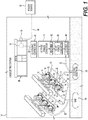
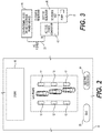
- FIGS. 1 and 2 A gas/electric station 10 according to the present invention is shown in FIGS. 1 and 2 .
- the gas/electric station 10 is structured, arranged, and designed to both dispense fuel (e.g. gas, diesel, propane) and recharge EVs.
- fuel e.g. gas, diesel, propane
- the gas/electric station 10 comprises multiple gas/electric pumps 12.
- the gas/electric pumps 12 each comprise an electric vehicle charger or EV charger and a fuel pump for refueling a vehicle with fuel (e.g. gasoline, diesel, gas, propane).
- the gas/electric pumps 12 each can comprise electrical components such as electrical components for charging EVs (e.g. DC-DC converter, battery(ies), Li-ion battery(ies)) and for refueling conventional internal combustion engines (e.g. fuel pump, fuel meter, fuel filter, electrical control), for example, within a housing or compartment(s) of the gas/electric pumps 12.
- the gas/electric pumps 12 are shown in FIG. 1 as three (3) gas/electric pumps 12 per row with two (2) rows. However, more or less gas/electric pumps 12 can be provided in the rows, or more or less rows can exist.
- the gas/electric pumps 12 each have a display 14, electric charging cable 16A with an electrical connector 16B configured for EV hook up and recharging, a gas hose 18A fitted with a gas nozzle 18B, a DC-DC converter 60, and an internal Li-ion battery array 19.
- the gas/electric pumps 12 can be "electric only” or “gas only” pumps, chargers, or devices arranged to provide gas pumps spaced apart from EV chargers at various arrangement and/or locations on the premise of the gas/electric station 10.
- the gas/electric pumps 12 shown comprise the components or parts for both pumping gas and EV charging.
- the gas/electrical pumps 12 can comprise the Li-ion battery(ies) or Li-ion battery array(s) 19, electronic controller configured to control voltage and current supplied by the Li-ion battery array or assembly 19 to the electric vehicle (EV), fuel pump components, and/or safety electronics (e.g. stop all dispensing, stop EV charging, stop fuel pumping, trigger Halon fire system, electrical spark suppression, operational lock out detection and controls for "gas only" filling mode or "electric charging only” charging mode).
- EV electric vehicle
- fuel pump components e.g. stop all dispensing, stop EV charging, stop fuel pumping, trigger Halon fire system, electrical spark suppression, operational lock out detection and controls for "gas only" filling mode or "electric charging only” charging mode.
- the arrangement shown in FIGS. 1 and 2 can be modified with the rows of gas/electric pumps 12 shown replaced with one or more rows of "gas only” pumps and one or more rows of "electric charging only” pumps physically spaced apart and separate same for safety reasons (e.g. to prevent fuel vapor in proximity to electric equipment and potential electrical sparks).
- the gas/electric pumps 12 can be configured or designed to provide electric spark suppression, high level of electrical grounding, redundant electrical grounding, separate compartments or containment structures for separate gas and electric operations, air venting or air or gas (e.g. nitrogen) circulation pumps to allow both gas and electric operations within the same gas/electric pumps 12.
- the gas/electric pumps 12 can be configured or designed to only allow one mode of operation at a time, for example, with a time pause in-between operations to allow air venting or circulations pumps to remove any remaining fuel or fuel vapor to atmosphere after gas operation mode.
- the gas/electric station 10 comprises an underground gas storage tank 20 connected to the individual gas/electric pumps 12 via a main gas supply line 22 connected to and supplying individual gas lines 24 (i.e. gas distribution arrangement and system).
- the gas/electric station 10 further comprises an underground electrical power reservoir 26 connected to the individual gas/electric pumps 12 via a main power line 28 connected to and supplying individual electric lines 30 (i.e. electric distribution arrangement and system).
- the gas/electric station 10 is anticipated to provide high speed recharging of electric vehicles (e.g. configured to recharge electrical vehicles (EVs) in 5 to 15 minutes) in a similar time frame to filling up a vehicle with gas.
- electric vehicles e.g. configured to recharge electrical vehicles (EVs) in 5 to 15 minutes
- multiple gas tanks 20 and/or multiple electrical power reservoirs 26 can be provided at the gas/electric station 10 to meet greater and/or peak demands.
- the electrical power reservoir 26 can be an apparatus or device configured to store a large amount of electrical power.
- the electrical power reservoir 26 can be a flow battery and/or Li-ion battery (e.g. banks of batteries).
- the electrical power reservoir can be a large flow battery connected to a series of Li-ion batteries configured to fast charging of an EV.
- the electrical power reservoir 26 can be designed, constructed, and sized to accommodate demand modeled based upon the forecasted number of EVs to be recharged on daily, weekly, monthly, and yearly schedules.
- the electrical power reservoir 26 is supplied power via underground power line 32 connected to an electrical panel 34, for example, located in store 36.
- a high power service line 38 supplies power from a power source 40 (e.g. power grid, transmission line, transmission station, generator).
- a power meter 35 e.g. located on side of store 36) can be provided to meter the incoming power from the power source 40.
- an electronic controller 41 can be provided in the power line 32 for controlling the charging of the electrical power reservoir 26 via the power line 32.
- the electronic controller 41 can be a component or part of the electrical power reservoir 26 or a separate component or part (e.g. located on the premises of the gas/electric station 10).
- the electronic controller 41 for example, can be a programmable electronic controller 41.
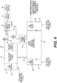
- an AC/DC converter 43 can be provided in the power line 32 for converting the incoming AC power into DC power for charging of the electrical power reservoir 26 via the power line 32, as shown in FIGS. 1 and 3 .
- the AC/DC converter 43 can be a component or part of the electrical power reservoir 26 or a separate component or part (e.g. located on the premises of the gas/electric station 10).
- the electrical power reservoir 26 can be recharged in various manners.
- the electrical power reservoir 26 is continuously charged, charged on demand, and/or charged according to a program or algorithm.
- the charging strategy can be to charge the electrical power reservoir 26 in a manner reducing or minimizing the demand (e.g. avoiding peak demand on the power source 40) while meeting the demand for charging the forecasted number of vehicles throughout the daily schedule.
- the program or algorithm can be configured to learn and store data on the amount of demand at a given time during each particular day throughout the year, season (e.g. summer, fall, winter, and spring), and holidays to update and improve the forecast for demand in the future.
- the charging of the electrical power reservoir 26 can involve continuous charging the electrical power reservoir 26 at an even or varying rate.
- the electrical power reservoir 26 can be intermittently recharged at a fixed rate, and/or charged at different rates at different period of time.
- the intent is to structure and arrange the gas/electric station 10 to provide enough power availability to always meet peak demands for recharging EVs at the gas/electric station 10 while minimizing peak power demands on the power source 40.
- the gas/electric station 10 is shown in FIGS. 1-3 , and/or another operation (e.g. lot located at a different location, for example, a remote location) can be fitted with electric units 126, 226, as shown in FIG. 4 .
- the units 126, 226 shown are structured and arranged for providing electric recharging only; however, the units 126, 226 can be modify to provide both gas refueling for conventional vehicles or electric recharging for EVs.
- the electric units 126, 226 can be connected to and powered, for example, by electric panel 34 of the gas/electric station 10.
- the portable version of electric units 126, 226 can be portable electric units.
- a 20 foot mobile storage container can be fitted with an electric pump 12, and a 40 foot mobile storage container can be fitted with two (2) electric pumps 12.
- the portable units 126, 226 can be transported to a site (e.g. new station site, local station site, remote station site), and connected up to start operating.
- the portable version of the electric units 126, 226 can be particularly useful for providing temporary operation, remote operation and provide inexpensive, reusable, or repositionable operation.
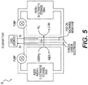
- the electric power reservoir 26 shown in FIGS. 1-3 can be a flow battery 50 shown in FIG. 5 .
- the flow battery 50 can be structured, configured, and or designed for use as the electric power reservoir 26 in the gas/electric station 10 shown in FIGS. 1-3 or the portable versions of the electric units 126 and 226 shown in FIG. 3 .
- the flow battery 50 comprises an AQDS/AQDSH electrolyte storage tank having a circulating pump, and an HBr/Br 2 electrolyte storage tank having another circulating pump along with a pair of spaced apart porous carbon electrodes separated by a proton exchange membrane.
- the flow battery 50 is connected to the electrical supply cable 32 (electric source) and the main power supply cables 22 leading to the gas/electric pumps 12 to supply same.
- At least one DC to DC converter 60 can receive power from the electric reservoir 26 and then supply power to the gas/electric pumps 12.
- the converter 60 can be a component or part of the electrical power reservoir 26 and/or a component or part of the gas/electric pumps 12.
- the electric reservoir 26 can be a one or more flow batteries 50.
- the open circuit voltage of a redox flow battery cell stack is directly proportional to the number of stacks in series, like any other battery.
- the voltage provided by the flow battery 50 must be adjustable to the level to which the EV battery needs to be charged to (e.g. may assume several different intermediate levels during the charge process).
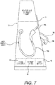
- a properly designed DC-DC converter 60 e.g. housed in the gas/electric pump 12, as shown in FIG. 7 ) with appropriate sensing and feedback mechanisms, following the flow battery, provides for the desired voltage to charge the EV battery.
- Tesla Model S has a battery voltage of approximately 350Vdc.
- the voltage available from the electric reservoir 26 (e.g. flow battery 50) itself will depend on its configuration (i.e. number of cells in a stack, number of stacks in series). For instance, the following has been demonstrated with Vanadium flow batteries installed in 2009, including 3 cell stacks with 40 cells in each stack. The stacks are electrically connected in series, which gives a potential of about 165 V ( Ris ⁇ National Laboratory for Sustainable Energy Report, Ris ⁇ -R-1753(EN), Feb. 2011, Technical University of Denmark ).
- This voltage may be increased by adding more cell stacks in series.
- Another way to increase the voltage to the desired charge level is to use a power electronic boost converter in the DC-DC converter 60 present at the gas/electric pump 12.
- the choice of topology to get to the desired charge voltage will depend on the economics of each option and the physical space (real estate) required by each option.
- the output voltage of the DC-DC converter 60 will depend on the EV model being charged, which may have vastly different battery voltages or charge port form factor. It is conceivable that the DC-DC converter power electronics may be able to provide the required voltage level for a certain range of battery voltages. If the EV battery voltage requirement is beyond what a single DC-DC converter 60 design can provide or an entirely different charge port form factor, then a different pump type 212 will need to be provided, interfacing the same electric reservoir 26 (e.g. flow battery 50).
- Any EV battery will need to be charged at a current level recommended by its manufacturer, which must not exceed a maximum current level to protect the EV battery and to limit the voltage drop in the cables connecting to the charge inlet port on the EV.
- the current limit function in the DC-DC converter 60 will provide that protection.
- the DC-DC converter 60 will be of the "buck" type, consisting of either MOSFET or IGBT type power electronic switches. Due to the high current involved during fast charging it would be preferred to operate the switches with a low loss switching approach, such as "zero-voltage switching" and synchronous rectification.
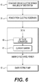
- the DC-DC converter 60 would then simply consist of the power electronic switches arranged in a "half-bridge” followed by a current limiter 61 (e.g. LC filter) to reduce the voltage ripple caused by the power electronic switching mechanism.
- the DC-DC converter 60 will have a first "boost” stage, followed by a “DC link” capacitor, followed by a “buck” stage and the LC filter.
- the "boost” stage steps up voltage available from the flow battery to a higher voltage, which is then down-converted to the EV battery voltage as required during the charge process. The operation of both the boost and buck stage would again be done while minimizing the losses in the converter.
- the AC-DC power converter 43 located after the AC power source 40 supplying the electrical panel 40 or the cable 32 can incorporate a rectifier 62 stage followed by a DC-DC converter 64 stage.
- the rectifier 62 stage is needed to convert the AC voltage to a DC voltage.
- the DC-DC converter 64 or converter stage 64 is required to convert the rectified (DC) voltage to the flow battery 26 voltage, as required during its charging process.
- the rectifier stage is typically of the full bridge "controlled rectifier" type implemented using MOSFET or IGBT type switches. The rectifier stage will be controlled to achieve "power factor correction" on its AC side to meet the power quality requirement set by the utility.
- the DC-DC converter 64 stage may be a "buck” type or a “boost” followed by a “buck” type, depending on whether the flow battery voltage is lower or higher, respectively, than the rectified voltage.
- the DC-DC converter 64 stage can include an LC filter 66 to remove the voltage ripple caused by the power electronic switching mechanism. Again, the power electronic switches will need to be operated to minimize the losses.
- the high energy cable will be capable of safely delivering 350KW of power to recharge the vehicle.
- Large copper cables must be used to manage this much power.
- the power will be a combination of voltage and current. Electric vehicles today are being built using batteries as high as 350-400VDC. In the future, this voltage is going to be higher to support longer driving distances as well as faster speeds.
- the charge currents are expected to be 400-500amps to provide Fast Charge success.
- the charge cable must be made using 0000AWG (approximately 0.5" diameter) or larger diameter to handle the charge currents required.
- the interface to the vehicle must be large conductors also.
- One large cable or two smaller cables can be used to provide the necessary power delivery. The advantage of two cables is they would make it easier to handle between the EV power pump and the EV.
- the two cables connection can also be used as a safety key for the charging process. More specifically, the EV power pump must detect solid connections of both conductors to enable the charge process to begin. An "electronic safety key/lock" will also be used to insure that the connection to the pump is a valid EV ready to be charged.
- This safety key can be part of the pumps safety software and the EV must provide a valid response in order for the pump to be enabled. In this way, the pump will never turn high power on to the cables unless it safely and clearly determines that a valid EV is connected and ready to charge.
- the conductors between the EV power pump and the EV must be made of highly conductive heavy gauge metal such as copper or silver and must be a low corrosion type.
- the connectors at the end of the pump cable must not have any exposed metal parts for safety purposes, and if two cables are used the cables must be either interchangeable or must be keyed so they cannot be improperly inserted.
- Charge interruption safety will also be provided to protect against accidents such as a person trying to drive away during the charge process or even environmental accidents such as earthquakes.
- An Inhibit signal will be provided from the pump that the EV manufacturer can use to disable the EV from driving during the charge process. But just in case the cable is accidentally pulled out of the pump during the charge process, the pump will detect this condition and shut power off so that it is not available to the outside world.
- a master shut off lever will also be provided that turns power off from the Battery Reservoir for safety purposes.
- the high speed electric vehicle recharge station and system can include a maximum power sharing function between charging the energy reservoir and charging the EV, as shown in FIG. 8 .
- the energy reservoir 26 used is a Redox Flow Battery 50, it cannot be charged while delivering power to the output. This is because the pump flow changes direction accordingly. Because of this limitation, it is possible to utilize the extra power normally being used for charging the Redox Flow Battery to assist in charging the actual EV.
- This feature allows for relay switching for selecting a charging target.
- the Redox Battery can be selected and continually charged.
- the system can switch the selection over to provide maximum charge to the EV by delivering the power that was going to the energy reservoir to the EV.
- the charger 43' ( FIG. 8 ) can comprise the AC TO DC POWER CONVERTER 43 shown in FIG. 1 along with other electrical components or part to configure the charger 43' for charging the electric reservoir 26.
- the charge 43' can be a different type of charger compared to the AC TO POWER CONVERTER 43.
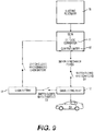
- This type of feature can be similarly applied to the gas/electric pump 12, as shown in FIG. 9 .
- the DC power from the electric reservoir 26 is directed to the DC-DC converter 60.
- the DC-DC power from the DC-DC converter 60 can be selectively used to charge the Li-ion battery 19 or can be used to charge the EV being charged by the gas/electric pump 12. Alternatively, power from the DC-DC converter 60 and the Li-ion battery 19 can simultaneously be used to charge the EV due to the switching arrangement shown in FIG. 9 .
- FIGS. 8 and 9 can be separate or combined together into the gas/electric station 10.
Landscapes
- Engineering & Computer Science (AREA)
- Power Engineering (AREA)
- Transportation (AREA)
- Mechanical Engineering (AREA)
- Charge And Discharge Circuits For Batteries Or The Like (AREA)
- Electric Propulsion And Braking For Vehicles (AREA)
- Control Of Eletrric Generators (AREA)
Claims (31)
- Station de charge de véhicule électrique (VE) permettant de charger un véhicule électrique (VE), comprenant un ou plusieurs batteries, la station de charge de VE comprenant :une source de puissance CA ;un convertisseur de puissance CA en CC conçu et agencé pour recevoir une puissance CA provenant de la source de puissance CA et convertir la puissance CA en une puissance CC ;un premier réservoir électrique destiné à recevoir une puissance CC pour charger le réservoir à partir du convertisseur de puissance CA en CC ;un convertisseur CC en CC conçu et agencé pour recevoir une puissance CC provenant du premier réservoir électrique et convertir la puissance CC en une puissance CC ; etun chargeur de VE conçu et agencé pour recevoir une puissance CC provenant du convertisseur CC en CC et convertir la puissance CC en une puissance CC adaptée pour charger le VE, le chargeur de VE comprenant au moins un composant électrique pour charger le VE,dans laquelle le convertisseur CC en CC est électriquement connecté entre le premier réservoir électrique et le chargeur de VE,
dans laquelle le chargeur de VE comprend une batterie Li-ion qui est connectée à la sortie du convertisseur CC en CC, etdans laquelle le chargeur de VE est conçu et agencé pour délivrer sélectivement ou simultanément une puissance pour charger le VE à la fois à partir de la sortie du convertisseur CC en CC et de la batterie Li-ion du chargeur de VE. - Station selon la revendication 1, dans laquelle le chargeur de VE est conçu et agencé pour charger le VE avec une puissance provenant du premier réservoir de puissance électrique.
- Station selon la revendication 2, dans laquelle la station comprend une pompe qui est connectée ou peut être connectée en circuit avec le convertisseur CC en CC, la pompe étant conçue et agencée pour recevoir une puissance CC provenant du convertisseur CC en CC.
- Station selon la revendication 3, dans laquelle la pompe est conçue pour se connecter au VE et le charger, la pompe est en circuit avec le premier réservoir de puissance électrique, la pompe est conçue et agencée pour recevoir une puissance provenant du premier réservoir de puissance électrique.
- Station selon la revendication 3 ou 4, dans laquelle la pompe est conçue pour se connecter au VE et le charger et est conçue et agencée pour fournir simultanément ou sélectivement une puissance pour charger le VE à partir de la sortie du convertisseur CC en CC et de la batterie Li-ion.
- Station selon l'une quelconque des revendications 3 à 5, dans laquelle la pompe est conçue pour distribuer de l'essence à un véhicule à essence et conçue pour se connecter au VE et le charger.
- Station selon l'une quelconque des revendications 3 à 6, dans laquelle la pompe comprend un logement de pompe, un tuyau d'essence s'étendant à partir du logement de pompe, une buse d'essence connectée au tuyau d'essence, un câble de charge s'étendant à partir du logement de pompe, et un connecteur de VE connecté au câble de charge.
- Station selon l'une quelconque des revendications 3 à 7, dans laquelle la pompe comprend un logement ou compartiment, la pompe étant connectée en circuit avec le premier réservoir de puissance électrique, le chargeur de VE étant situé à l'intérieur du logement ou compartiment de la pompe.
- Station selon l'une quelconque des revendications 2 à 8, dans laquelle la station comprend des pompes multiples et les pompes multiples sont alimentées en puissance par la source de puissance CA et/ou le premier réservoir de puissance électrique.
- Station selon la revendication 9, dans laquelle les multiples pompes sont chacune conçues pour distribuer de l'essence à un véhicule à essence et conçues pour se connecter au VE et le charger.
- Station selon l'une quelconque des revendications précédentes, incluant un limiteur de courant prévu entre le convertisseur CC en CC et le chargeur de VE.
- Station selon l'une quelconque des revendications précédentes, dans laquelle le convertisseur de puissance CC en CC est conçu et agencé pour recevoir une puissance provenant du convertisseur de puissance AC en CC.
- Station selon l'une quelconque des revendications précédentes, dans laquelle le convertisseur CC en CC est en outre connecté en circuit avec la source de puissance CA.
- Station selon l'une quelconque des revendications précédentes, dans laquelle la station comprend un deuxième convertisseur CC en CC situé entre le convertisseur CA en CC et le premier réservoir de puissance électrique.
- Station selon l'une quelconque des revendications précédentes, dans laquelle le convertisseur CA en CC comprend un redresseur conçu et agencé pour convertir la puissance CA provenant de la source de puissance en une puissance CC, et un troisième convertisseur CC en CC pour convertir la puissance CC provenant du redresseur du convertisseur CA en CC en une puissance CC adaptée pour recharger le premier réservoir de puissance électrique.
- Station selon l'une quelconque des revendications précédentes, dans laquelle le convertisseur CA en CC comprend un filtre électrique conçu et agencé pour recevoir une puissance CC provenant d'un deuxième convertisseur CC en CC avant que la puissance ne soit délivrée au premier réservoir de puissance électrique.
- Station selon la revendication 16, dans laquelle le filtre électrique est un filtre LC.
- Station selon l'une quelconque des revendications précédentes, dans laquelle la station est conçue et agencée de telle sorte que la tension fournie par le premier réservoir de puissance électrique pour charger une batterie de VE est réglable et prend plusieurs niveaux intermédiaires différents pendant un processus de charge.
- Station selon l'une quelconque des revendications précédentes, dans laquelle le convertisseur CC en CC est conçu et agencé pour fournir de multiples étages de conversion de tension.
- Station selon l'une quelconque des revendications précédentes, dans laquelle le convertisseur CC en CC est conçu et agencé pour fournir un étage d'amplification pour augmenter la tension suivi d'un étage abaisseur pour convertir par abaissement la tension en une tension d'une batterie de VE.
- Station selon l'une quelconque des revendications précédentes, dans laquelle le premier réservoir de puissance électrique comprend une batterie à circulation.
- Station selon l'une quelconque des revendications précédentes, dans laquelle le premier réservoir de puissance électrique comprend une batterie Li-ion.
- Station selon l'une quelconque des revendications précédentes, dans laquelle la station est conçue et agencée pour délivrer sélectivement ou simultanément une puissance au convertisseur CC en CC à partir du premier réservoir de puissance électrique ou du convertisseur CA en CC.
- Station selon l'une quelconque des revendications précédentes, comprenant en outre un dispositif de commande électronique conçu et agencé pour commander la charge du premier réservoir de puissance électrique.
- Station selon l'une quelconque des revendications précédentes, dans laquelle la station comprend de multiples chargeurs de VE.
- Station selon l'une quelconque des revendications précédentes, dans laquelle la station de charge est conçue pour fournir au moins 350 kW pour recharger le VE.
- Station selon l'une quelconque des revendications précédentes, dans laquelle la station de charge est conçue pour charger rapidement le VE à des courants de charge de 400-500 ampères.
- Station selon l'une quelconque des revendications précédentes, dans laquelle la station comprend un troisième convertisseur CC en CC, et le troisième convertisseur CC en CC est situé à l'intérieur de la pompe.
- Station selon l'une quelconque des revendications précédentes, dans laquelle la station comprend en outre plusieurs pompes uniquement à essence.
- Station selon l'une quelconque des revendications précédentes, dans laquelle la station comprend une ou plusieurs rangées de pompes uniquement à essence, et une ou plusieurs rangées de pompes électriques ou de rechargeurs de VE uniquement de charge électrique.
- Station selon la revendication 30, dans laquelle plusieurs pompes de charge électrique sont agencées dans une rangée, et dans laquelle plusieurs pompes uniquement à essence sont agencées dans une autre rangée.
Applications Claiming Priority (3)
| Application Number | Priority Date | Filing Date | Title |
|---|---|---|---|
| US201762476499P | 2017-03-24 | 2017-03-24 | |
| EP18771346.6A EP3600947B1 (fr) | 2017-03-24 | 2018-03-23 | Station et système de recharge rapide de véhicule électrique (ev) |
| PCT/US2018/024058 WO2018175904A1 (fr) | 2017-03-24 | 2018-03-23 | Station et système de recharge rapide de véhicule électrique (ev) |
Related Parent Applications (2)
| Application Number | Title | Priority Date | Filing Date |
|---|---|---|---|
| EP18771346.6A Division-Into EP3600947B1 (fr) | 2017-03-24 | 2018-03-23 | Station et système de recharge rapide de véhicule électrique (ev) |
| EP18771346.6A Division EP3600947B1 (fr) | 2017-03-24 | 2018-03-23 | Station et système de recharge rapide de véhicule électrique (ev) |
Publications (2)
| Publication Number | Publication Date |
|---|---|
| EP3736169A1 EP3736169A1 (fr) | 2020-11-11 |
| EP3736169B1 true EP3736169B1 (fr) | 2021-11-17 |
Family
ID=63585776
Family Applications (4)
| Application Number | Title | Priority Date | Filing Date |
|---|---|---|---|
| EP18771346.6A Active EP3600947B1 (fr) | 2017-03-24 | 2018-03-23 | Station et système de recharge rapide de véhicule électrique (ev) |
| EP21198998.3A Active EP3950413B1 (fr) | 2017-03-24 | 2018-03-23 | Véhicule électrique (ev) station et système de recharge rapide |
| EP21198999.1A Pending EP3950414A1 (fr) | 2017-03-24 | 2018-03-23 | Station de recharge rapide de véhicule électrique (ve) comportant plusieurs réservoirs de puissance |
| EP20182706.0A Active EP3736169B1 (fr) | 2017-03-24 | 2018-03-23 | Station et système de recharge rapide de véhicule électrique (ev) |
Family Applications Before (3)
| Application Number | Title | Priority Date | Filing Date |
|---|---|---|---|
| EP18771346.6A Active EP3600947B1 (fr) | 2017-03-24 | 2018-03-23 | Station et système de recharge rapide de véhicule électrique (ev) |
| EP21198998.3A Active EP3950413B1 (fr) | 2017-03-24 | 2018-03-23 | Véhicule électrique (ev) station et système de recharge rapide |
| EP21198999.1A Pending EP3950414A1 (fr) | 2017-03-24 | 2018-03-23 | Station de recharge rapide de véhicule électrique (ve) comportant plusieurs réservoirs de puissance |
Country Status (7)
| Country | Link |
|---|---|
| US (4) | US10730396B2 (fr) |
| EP (4) | EP3600947B1 (fr) |
| JP (2) | JP6921979B2 (fr) |
| AU (3) | AU2018237596A1 (fr) |
| CA (3) | CA3222488A1 (fr) |
| GB (1) | GB2627413A (fr) |
| WO (1) | WO2018175904A1 (fr) |
Families Citing this family (20)
| Publication number | Priority date | Publication date | Assignee | Title |
|---|---|---|---|---|
| EP3600947B1 (fr) | 2017-03-24 | 2021-10-20 | The Noco Company | Station et système de recharge rapide de véhicule électrique (ev) |
| US11600996B2 (en) * | 2017-03-24 | 2023-03-07 | The Noco Company | Electric vehicle (EV) fast recharge station and system |
| US20230299618A1 (en) * | 2017-05-16 | 2023-09-21 | Wireless Electrical Grid Lan, Wigl Inc. | Wireless communication device and method of using |
| DE102017115642B3 (de) * | 2017-07-12 | 2018-07-19 | Dr. Ing. H.C. F. Porsche Aktiengesellschaft | Verfahren und Vorrichtung zum elektrischen Laden von Elektrofahrzeugen |
| DE102017115631A1 (de) * | 2017-07-12 | 2019-04-11 | Dr. Ing. H.C. F. Porsche Aktiengesellschaft | Vorrichtung zum Laden mindestens einer Batterie |
| US20190228432A1 (en) * | 2018-01-24 | 2019-07-25 | Maverik, Inc. | Leveraging loyalty information in custom interfaces |
| LT6775B (lt) | 2019-02-07 | 2020-10-26 | MIKALAUSKAS ArtÅ«ras | Elektromobilių įkrovimo stotelė ir valdymo būdas |
| EP3790148A1 (fr) * | 2019-09-03 | 2021-03-10 | Universität der Bundeswehr München | Système de charge pour véhicules électriques |
| US11390182B2 (en) * | 2019-09-12 | 2022-07-19 | Zayo Group, Llc | Integrated data and charging station |
| US12570163B2 (en) * | 2019-09-25 | 2026-03-10 | Enevate Corporation | Method and system for collocated gasoline pumps and charging stations for ultra-high speed charging |
| FR3110787B1 (fr) * | 2020-05-20 | 2022-07-08 | Ineo Urban Transp Solutions | Station de recharge pour flottes de vehicules electriques |
| DE102020114677A1 (de) | 2020-06-02 | 2021-12-02 | Me Energy Gmbh | Ladesäule |
| US12139031B2 (en) | 2020-07-23 | 2024-11-12 | Marscharge, Inc. | Charging system employing battery storage |
| CN116133891B (zh) * | 2020-08-04 | 2025-10-10 | 尼科公司 | 电动车辆(ev)快速再充电站和系统 |
| KR20230020165A (ko) * | 2021-08-03 | 2023-02-10 | 현대자동차주식회사 | 이동식 전기차 충전 시스템 |
| CN113561824B (zh) * | 2021-08-09 | 2023-04-18 | 四川帝威能源技术有限公司 | 一种加氢充电一体桩及余热回收系统 |
| US11855470B2 (en) * | 2021-09-23 | 2023-12-26 | Fluidity Power LLC | Mobile generator charging system and method |
| US12576732B2 (en) * | 2022-12-07 | 2026-03-17 | Rivian Ip Holdings, Llc | Power transmission between electric vehicle battery and alternating-current power system |
| US20240416781A1 (en) * | 2023-06-14 | 2024-12-19 | Mutlaq Senhat Z. ALOTAIBI | Mobile and Stationed Electrical Vehicles Charging System |
| WO2026020138A1 (fr) * | 2024-07-19 | 2026-01-22 | Lyra Energy Solutions Inc | Chargeur embarqué multifonction pour véhicules électriques à deux ou trois roues |
Family Cites Families (50)
| Publication number | Priority date | Publication date | Assignee | Title |
|---|---|---|---|---|
| JP2780167B2 (ja) * | 1993-01-22 | 1998-07-30 | 東光株式会社 | Ac−dcコンバータ |
| US7256516B2 (en) | 2000-06-14 | 2007-08-14 | Aerovironment Inc. | Battery charging system and method |
| JP3971316B2 (ja) | 2003-01-31 | 2007-09-05 | 関西電力株式会社 | 瞬時大電力供給装置 |
| JP4135155B2 (ja) | 2004-07-02 | 2008-08-20 | 日産自動車株式会社 | 充電スタンド |
| US7523770B2 (en) * | 2005-12-12 | 2009-04-28 | Exxonmobil Research And Enginnering Company | Service station for serving requirements of multiple vehicle technologies |
| CN101150259B (zh) * | 2006-09-18 | 2010-05-12 | 比亚迪股份有限公司 | 电动车充电系统 |
| JP4807329B2 (ja) | 2007-06-14 | 2011-11-02 | トヨタ自動車株式会社 | ハイブリッド車両およびハイブリッド車両運用システム |
| US8785023B2 (en) | 2008-07-07 | 2014-07-22 | Enervault Corparation | Cascade redox flow battery systems |
| US20130011704A1 (en) | 2008-07-07 | 2013-01-10 | Enervault Corporation | Redox Flow Battery System with Multiple Independent Stacks |
| JP5592274B2 (ja) | 2009-01-19 | 2014-09-17 | 株式会社エネルギー応用技術研究所 | 直流給電システム |
| US20100228415A1 (en) * | 2009-03-05 | 2010-09-09 | Sunil Paul | System and method for reducing the cost of efficient vehicles |
| JP2012034554A (ja) | 2009-08-21 | 2012-02-16 | Jfe Engineering Corp | 急速充電装置 |
| US8773095B2 (en) * | 2009-12-29 | 2014-07-08 | Texas Instruments Incorporated | Startup circuit for an LDO |
| JP5016121B2 (ja) | 2010-02-19 | 2012-09-05 | Jfeエンジニアリング株式会社 | 急速充電装置及び移動式充電装置 |
| TW201230598A (en) | 2010-04-26 | 2012-07-16 | Proterra Inc | Fast charge stations for electric vehicles in areas with limited power availability |
| JP2011259572A (ja) * | 2010-06-08 | 2011-12-22 | Honda Motor Co Ltd | 充電器および充電システム |
| US8758914B2 (en) * | 2010-06-18 | 2014-06-24 | Polyplus Battery Company | Li-Ion/polysulfide flow battery |
| US20120074901A1 (en) | 2010-09-27 | 2012-03-29 | Tim Mohammed | Centralized charging station |
| CN102114801A (zh) * | 2011-02-21 | 2011-07-06 | 新康电脑科技(苏州)有限公司 | 基于高速公路区间的行驶轿车集中运载系统 |
| JP2012172500A (ja) | 2011-02-24 | 2012-09-10 | Sekisui Jushi Co Ltd | 充電スタンド設置施設 |
| JP5541210B2 (ja) | 2011-03-29 | 2014-07-09 | 株式会社デンソー | 電力分配装置 |
| JP2013027177A (ja) | 2011-07-21 | 2013-02-04 | Sumitomo Electric Ind Ltd | 配電システム |
| US9153847B2 (en) * | 2011-11-04 | 2015-10-06 | Honda Motor Co., Ltd. | Grid connected solar battery charging device for home and vehicle energy management |
| JP5723811B2 (ja) | 2012-03-13 | 2015-05-27 | 株式会社トライネット | 電気自動車の充電装置及び充電システム |
| US20130257146A1 (en) * | 2012-04-03 | 2013-10-03 | Geraldo Nojima | Electric vehicle supply equipment for electric vehicles |
| US20150207316A1 (en) * | 2012-08-16 | 2015-07-23 | Robert Bosch Gmbh | Dc building system with energy storage and control system |
| WO2014068733A1 (fr) * | 2012-10-31 | 2014-05-08 | Jfeエンジニアリング株式会社 | Chargeur rapide pour un véhicule électrique |
| US9637016B2 (en) * | 2012-12-14 | 2017-05-02 | Agim GJINALI | Fast charging system for electric vehicles |
| US20140191718A1 (en) * | 2013-01-09 | 2014-07-10 | Stacey Reineccius | Secure authentication for fueling of vehicles |
| JP2014230301A (ja) * | 2013-05-17 | 2014-12-08 | 株式会社エネルギー応用技術研究所 | 急速充電用電力供給システム |
| FR3008041B1 (fr) * | 2013-07-05 | 2016-12-09 | Blue Solutions | Vehicule electrique et installation de transport associee |
| US9586497B2 (en) * | 2013-08-22 | 2017-03-07 | Lightening Energy | Electric vehicle recharging station including a battery bank |
| CA2862950A1 (fr) | 2013-09-11 | 2015-03-11 | Proterra Inc. | Procedes et systemes de charge de vehicule electrique |
| JP2015109724A (ja) * | 2013-12-03 | 2015-06-11 | 株式会社豊田自動織機 | 非接触電力伝送装置及び受電機器 |
| KR101528079B1 (ko) | 2013-12-27 | 2015-06-10 | 두산중공업 주식회사 | 배터리 교환 스테이션 및 배터리 교환 스테이션의 운영 방법 |
| JP6071923B2 (ja) | 2014-02-27 | 2017-02-01 | 株式会社東芝 | 充電システム |
| WO2015190123A1 (fr) * | 2014-06-13 | 2015-12-17 | 国立大学法人九州大学 | Installation d'alimentation en énergie autonome équipée d'une unité d'alimentation en combustible hydrogène de véhicule et d'un chargeur de véhicule électrique exploitant la lumière solaire |
| US20180198291A1 (en) * | 2014-09-03 | 2018-07-12 | Ho-Hsun David Kuo | Apparatus and method for intelligent battery optimization and equalization management system |
| JP6161127B2 (ja) | 2014-12-03 | 2017-07-12 | オムロンオートモーティブエレクトロニクス株式会社 | 電力変換装置 |
| JP6600161B2 (ja) | 2015-05-13 | 2019-10-30 | 株式会社キューヘン | 急速充電装置 |
| US20160341773A1 (en) * | 2015-05-18 | 2016-11-24 | Powertree Services, Inc. | Method for clear delineation of wholesale and retail energy usage and activity involving energy storage devices |
| DE112016002218T5 (de) | 2015-11-18 | 2018-04-19 | Next-E Solutions Inc. | Steuervorrichtung, elektrische Speichervorrichtung und elektrisches Speichersystem |
| US10183583B2 (en) | 2016-08-03 | 2019-01-22 | Solarcity Corporation | Energy generation and storage system with electric vehicle charging capability |
| US11600996B2 (en) | 2017-03-24 | 2023-03-07 | The Noco Company | Electric vehicle (EV) fast recharge station and system |
| EP3600947B1 (fr) | 2017-03-24 | 2021-10-20 | The Noco Company | Station et système de recharge rapide de véhicule électrique (ev) |
| DE102017108579A1 (de) | 2017-04-21 | 2018-10-25 | Wobben Properties Gmbh | Verfahren zum Betreiben einer Ladestation |
| US10189362B2 (en) * | 2017-05-31 | 2019-01-29 | Honda Motor Co., Ltd. | Vehicle charging station having degraded energy storage units for charging an incoming vehicle and methods thereof |
| GB2572758A (en) | 2018-04-05 | 2019-10-16 | Moog Unna Gmbh | Charging station for electric vehicles |
| DE102018003560A1 (de) | 2018-05-02 | 2019-11-07 | Voltabox Ag | Ladestation für elektrisch angetriebene Land-, Luft- und Wasserfahrzeuge und für stationäre Elektroenergiespeicher |
| US20220402390A1 (en) | 2019-11-14 | 2022-12-22 | Invertedpower Pty Ltd | A multimodal converter for interfacing with multiple energy sources |
-
2018
- 2018-03-23 EP EP18771346.6A patent/EP3600947B1/fr active Active
- 2018-03-23 JP JP2019552118A patent/JP6921979B2/ja active Active
- 2018-03-23 EP EP21198998.3A patent/EP3950413B1/fr active Active
- 2018-03-23 EP EP21198999.1A patent/EP3950414A1/fr active Pending
- 2018-03-23 CA CA3222488A patent/CA3222488A1/fr active Pending
- 2018-03-23 EP EP20182706.0A patent/EP3736169B1/fr active Active
- 2018-03-23 WO PCT/US2018/024058 patent/WO2018175904A1/fr not_active Ceased
- 2018-03-23 AU AU2018237596A patent/AU2018237596A1/en not_active Abandoned
- 2018-03-23 CA CA3056907A patent/CA3056907C/fr active Active
- 2018-03-23 CA CA3127239A patent/CA3127239C/fr active Active
- 2018-06-26 US US16/018,411 patent/US10730396B2/en active Active
-
2020
- 2020-07-06 US US16/921,029 patent/US11390176B2/en active Active
-
2021
- 2021-05-20 AU AU2021203245A patent/AU2021203245B2/en active Active
- 2021-07-28 JP JP2021123444A patent/JP7198880B2/ja active Active
- 2021-10-01 AU AU2021240310A patent/AU2021240310B2/en active Active
-
2022
- 2022-06-17 US US17/807,572 patent/US11949274B2/en active Active
- 2022-08-03 GB GB2408318.0A patent/GB2627413A/en active Pending
-
2024
- 2024-02-16 US US18/443,449 patent/US12512691B2/en active Active
Also Published As
| Publication number | Publication date |
|---|---|
| US12512691B2 (en) | 2025-12-30 |
| CA3056907C (fr) | 2022-09-06 |
| JP6921979B2 (ja) | 2021-08-18 |
| AU2021203245A1 (en) | 2021-06-10 |
| EP3950414A1 (fr) | 2022-02-09 |
| EP3600947A1 (fr) | 2020-02-05 |
| AU2021240310B2 (en) | 2023-07-13 |
| US11949274B2 (en) | 2024-04-02 |
| EP3600947A4 (fr) | 2020-09-09 |
| EP3950413B1 (fr) | 2026-01-28 |
| JP2020512802A (ja) | 2020-04-23 |
| AU2018237596A1 (en) | 2019-10-03 |
| US20240186815A1 (en) | 2024-06-06 |
| CA3127239A1 (fr) | 2018-09-27 |
| GB2627413A (en) | 2024-08-21 |
| EP3736169A1 (fr) | 2020-11-11 |
| CA3056907A1 (fr) | 2018-09-27 |
| GB202408318D0 (en) | 2024-07-24 |
| JP7198880B2 (ja) | 2023-01-04 |
| US20180297477A1 (en) | 2018-10-18 |
| US11390176B2 (en) | 2022-07-19 |
| EP3950413A1 (fr) | 2022-02-09 |
| WO2018175904A1 (fr) | 2018-09-27 |
| AU2021240310A1 (en) | 2021-10-28 |
| EP3600947B1 (fr) | 2021-10-20 |
| JP2021185733A (ja) | 2021-12-09 |
| US20200331354A1 (en) | 2020-10-22 |
| CA3127239C (fr) | 2024-01-23 |
| AU2021203245B2 (en) | 2021-07-01 |
| CA3222488A1 (fr) | 2018-09-27 |
| US20220314821A1 (en) | 2022-10-06 |
| US10730396B2 (en) | 2020-08-04 |
Similar Documents
| Publication | Publication Date | Title |
|---|---|---|
| US12512691B2 (en) | Electric vehicle (EV) fast recharge station and system | |
| US11600996B2 (en) | Electric vehicle (EV) fast recharge station and system | |
| JP7787963B2 (ja) | 電気自動車(ev)高速充電ステーション及びシステム |
Legal Events
| Date | Code | Title | Description |
|---|---|---|---|
| PUAI | Public reference made under article 153(3) epc to a published international application that has entered the european phase |
Free format text: ORIGINAL CODE: 0009012 |
|
| STAA | Information on the status of an ep patent application or granted ep patent |
Free format text: STATUS: THE APPLICATION HAS BEEN PUBLISHED |
|
| AC | Divisional application: reference to earlier application |
Ref document number: 3600947 Country of ref document: EP Kind code of ref document: P |
|
| AK | Designated contracting states |
Kind code of ref document: A1 Designated state(s): AL AT BE BG CH CY CZ DE DK EE ES FI FR GB GR HR HU IE IS IT LI LT LU LV MC MK MT NL NO PL PT RO RS SE SI SK SM TR |
|
| STAA | Information on the status of an ep patent application or granted ep patent |
Free format text: STATUS: REQUEST FOR EXAMINATION WAS MADE |
|
| 17P | Request for examination filed |
Effective date: 20210511 |
|
| RBV | Designated contracting states (corrected) |
Designated state(s): AL AT BE BG CH CY CZ DE DK EE ES FI FR GB GR HR HU IE IS IT LI LT LU LV MC MK MT NL NO PL PT RO RS SE SI SK SM TR |
|
| RIN1 | Information on inventor provided before grant (corrected) |
Inventor name: STANFIELD, JAMES RICHARD |
|
| GRAP | Despatch of communication of intention to grant a patent |
Free format text: ORIGINAL CODE: EPIDOSNIGR1 |
|
| STAA | Information on the status of an ep patent application or granted ep patent |
Free format text: STATUS: GRANT OF PATENT IS INTENDED |
|
| INTG | Intention to grant announced |
Effective date: 20210622 |
|
| GRAS | Grant fee paid |
Free format text: ORIGINAL CODE: EPIDOSNIGR3 |
|
| GRAA | (expected) grant |
Free format text: ORIGINAL CODE: 0009210 |
|
| STAA | Information on the status of an ep patent application or granted ep patent |
Free format text: STATUS: THE PATENT HAS BEEN GRANTED |
|
| AC | Divisional application: reference to earlier application |
Ref document number: 3600947 Country of ref document: EP Kind code of ref document: P |
|
| AK | Designated contracting states |
Kind code of ref document: B1 Designated state(s): AL AT BE BG CH CY CZ DE DK EE ES FI FR GB GR HR HU IE IS IT LI LT LU LV MC MK MT NL NO PL PT RO RS SE SI SK SM TR |
|
| REG | Reference to a national code |
Ref country code: GB Ref legal event code: FG4D |
|
| REG | Reference to a national code |
Ref country code: IE Ref legal event code: FG4D |
|
| REG | Reference to a national code |
Ref country code: DE Ref legal event code: R096 Ref document number: 602018027009 Country of ref document: DE |
|
| REG | Reference to a national code |
Ref country code: AT Ref legal event code: REF Ref document number: 1447779 Country of ref document: AT Kind code of ref document: T Effective date: 20211215 |
|
| REG | Reference to a national code |
Ref country code: NL Ref legal event code: FP |
|
| REG | Reference to a national code |
Ref country code: LT Ref legal event code: MG9D |
|
| REG | Reference to a national code |
Ref country code: AT Ref legal event code: MK05 Ref document number: 1447779 Country of ref document: AT Kind code of ref document: T Effective date: 20211117 |
|
| PG25 | Lapsed in a contracting state [announced via postgrant information from national office to epo] |
Ref country code: RS Free format text: LAPSE BECAUSE OF FAILURE TO SUBMIT A TRANSLATION OF THE DESCRIPTION OR TO PAY THE FEE WITHIN THE PRESCRIBED TIME-LIMIT Effective date: 20211117 Ref country code: LT Free format text: LAPSE BECAUSE OF FAILURE TO SUBMIT A TRANSLATION OF THE DESCRIPTION OR TO PAY THE FEE WITHIN THE PRESCRIBED TIME-LIMIT Effective date: 20211117 Ref country code: FI Free format text: LAPSE BECAUSE OF FAILURE TO SUBMIT A TRANSLATION OF THE DESCRIPTION OR TO PAY THE FEE WITHIN THE PRESCRIBED TIME-LIMIT Effective date: 20211117 Ref country code: BG Free format text: LAPSE BECAUSE OF FAILURE TO SUBMIT A TRANSLATION OF THE DESCRIPTION OR TO PAY THE FEE WITHIN THE PRESCRIBED TIME-LIMIT Effective date: 20220217 Ref country code: AT Free format text: LAPSE BECAUSE OF FAILURE TO SUBMIT A TRANSLATION OF THE DESCRIPTION OR TO PAY THE FEE WITHIN THE PRESCRIBED TIME-LIMIT Effective date: 20211117 |
|
| PG25 | Lapsed in a contracting state [announced via postgrant information from national office to epo] |
Ref country code: IS Free format text: LAPSE BECAUSE OF FAILURE TO SUBMIT A TRANSLATION OF THE DESCRIPTION OR TO PAY THE FEE WITHIN THE PRESCRIBED TIME-LIMIT Effective date: 20220317 Ref country code: SE Free format text: LAPSE BECAUSE OF FAILURE TO SUBMIT A TRANSLATION OF THE DESCRIPTION OR TO PAY THE FEE WITHIN THE PRESCRIBED TIME-LIMIT Effective date: 20211117 Ref country code: PT Free format text: LAPSE BECAUSE OF FAILURE TO SUBMIT A TRANSLATION OF THE DESCRIPTION OR TO PAY THE FEE WITHIN THE PRESCRIBED TIME-LIMIT Effective date: 20220317 Ref country code: PL Free format text: LAPSE BECAUSE OF FAILURE TO SUBMIT A TRANSLATION OF THE DESCRIPTION OR TO PAY THE FEE WITHIN THE PRESCRIBED TIME-LIMIT Effective date: 20211117 Ref country code: NO Free format text: LAPSE BECAUSE OF FAILURE TO SUBMIT A TRANSLATION OF THE DESCRIPTION OR TO PAY THE FEE WITHIN THE PRESCRIBED TIME-LIMIT Effective date: 20220217 Ref country code: LV Free format text: LAPSE BECAUSE OF FAILURE TO SUBMIT A TRANSLATION OF THE DESCRIPTION OR TO PAY THE FEE WITHIN THE PRESCRIBED TIME-LIMIT Effective date: 20211117 Ref country code: HR Free format text: LAPSE BECAUSE OF FAILURE TO SUBMIT A TRANSLATION OF THE DESCRIPTION OR TO PAY THE FEE WITHIN THE PRESCRIBED TIME-LIMIT Effective date: 20211117 Ref country code: GR Free format text: LAPSE BECAUSE OF FAILURE TO SUBMIT A TRANSLATION OF THE DESCRIPTION OR TO PAY THE FEE WITHIN THE PRESCRIBED TIME-LIMIT Effective date: 20220218 |
|
| PG25 | Lapsed in a contracting state [announced via postgrant information from national office to epo] |
Ref country code: SM Free format text: LAPSE BECAUSE OF FAILURE TO SUBMIT A TRANSLATION OF THE DESCRIPTION OR TO PAY THE FEE WITHIN THE PRESCRIBED TIME-LIMIT Effective date: 20211117 Ref country code: SK Free format text: LAPSE BECAUSE OF FAILURE TO SUBMIT A TRANSLATION OF THE DESCRIPTION OR TO PAY THE FEE WITHIN THE PRESCRIBED TIME-LIMIT Effective date: 20211117 Ref country code: RO Free format text: LAPSE BECAUSE OF FAILURE TO SUBMIT A TRANSLATION OF THE DESCRIPTION OR TO PAY THE FEE WITHIN THE PRESCRIBED TIME-LIMIT Effective date: 20211117 Ref country code: ES Free format text: LAPSE BECAUSE OF FAILURE TO SUBMIT A TRANSLATION OF THE DESCRIPTION OR TO PAY THE FEE WITHIN THE PRESCRIBED TIME-LIMIT Effective date: 20211117 Ref country code: EE Free format text: LAPSE BECAUSE OF FAILURE TO SUBMIT A TRANSLATION OF THE DESCRIPTION OR TO PAY THE FEE WITHIN THE PRESCRIBED TIME-LIMIT Effective date: 20211117 Ref country code: DK Free format text: LAPSE BECAUSE OF FAILURE TO SUBMIT A TRANSLATION OF THE DESCRIPTION OR TO PAY THE FEE WITHIN THE PRESCRIBED TIME-LIMIT Effective date: 20211117 Ref country code: CZ Free format text: LAPSE BECAUSE OF FAILURE TO SUBMIT A TRANSLATION OF THE DESCRIPTION OR TO PAY THE FEE WITHIN THE PRESCRIBED TIME-LIMIT Effective date: 20211117 |
|
| REG | Reference to a national code |
Ref country code: DE Ref legal event code: R097 Ref document number: 602018027009 Country of ref document: DE |
|
| PLBE | No opposition filed within time limit |
Free format text: ORIGINAL CODE: 0009261 |
|
| STAA | Information on the status of an ep patent application or granted ep patent |
Free format text: STATUS: NO OPPOSITION FILED WITHIN TIME LIMIT |
|
| 26N | No opposition filed |
Effective date: 20220818 |
|
| PG25 | Lapsed in a contracting state [announced via postgrant information from national office to epo] |
Ref country code: MC Free format text: LAPSE BECAUSE OF FAILURE TO SUBMIT A TRANSLATION OF THE DESCRIPTION OR TO PAY THE FEE WITHIN THE PRESCRIBED TIME-LIMIT Effective date: 20211117 Ref country code: AL Free format text: LAPSE BECAUSE OF FAILURE TO SUBMIT A TRANSLATION OF THE DESCRIPTION OR TO PAY THE FEE WITHIN THE PRESCRIBED TIME-LIMIT Effective date: 20211117 |
|
| REG | Reference to a national code |
Ref country code: CH Ref legal event code: PL |
|
| PG25 | Lapsed in a contracting state [announced via postgrant information from national office to epo] |
Ref country code: SI Free format text: LAPSE BECAUSE OF FAILURE TO SUBMIT A TRANSLATION OF THE DESCRIPTION OR TO PAY THE FEE WITHIN THE PRESCRIBED TIME-LIMIT Effective date: 20211117 |
|
| REG | Reference to a national code |
Ref country code: BE Ref legal event code: MM Effective date: 20220331 |
|
| PG25 | Lapsed in a contracting state [announced via postgrant information from national office to epo] |
Ref country code: LU Free format text: LAPSE BECAUSE OF NON-PAYMENT OF DUE FEES Effective date: 20220323 Ref country code: LI Free format text: LAPSE BECAUSE OF NON-PAYMENT OF DUE FEES Effective date: 20220331 Ref country code: IE Free format text: LAPSE BECAUSE OF NON-PAYMENT OF DUE FEES Effective date: 20220323 Ref country code: CH Free format text: LAPSE BECAUSE OF NON-PAYMENT OF DUE FEES Effective date: 20220331 |
|
| PG25 | Lapsed in a contracting state [announced via postgrant information from national office to epo] |
Ref country code: BE Free format text: LAPSE BECAUSE OF NON-PAYMENT OF DUE FEES Effective date: 20220331 |
|
| PG25 | Lapsed in a contracting state [announced via postgrant information from national office to epo] |
Ref country code: IT Free format text: LAPSE BECAUSE OF FAILURE TO SUBMIT A TRANSLATION OF THE DESCRIPTION OR TO PAY THE FEE WITHIN THE PRESCRIBED TIME-LIMIT Effective date: 20211117 |
|
| P01 | Opt-out of the competence of the unified patent court (upc) registered |
Effective date: 20230619 |
|
| PG25 | Lapsed in a contracting state [announced via postgrant information from national office to epo] |
Ref country code: MK Free format text: LAPSE BECAUSE OF FAILURE TO SUBMIT A TRANSLATION OF THE DESCRIPTION OR TO PAY THE FEE WITHIN THE PRESCRIBED TIME-LIMIT Effective date: 20211117 Ref country code: CY Free format text: LAPSE BECAUSE OF FAILURE TO SUBMIT A TRANSLATION OF THE DESCRIPTION OR TO PAY THE FEE WITHIN THE PRESCRIBED TIME-LIMIT Effective date: 20211117 |
|
| PG25 | Lapsed in a contracting state [announced via postgrant information from national office to epo] |
Ref country code: HU Free format text: LAPSE BECAUSE OF FAILURE TO SUBMIT A TRANSLATION OF THE DESCRIPTION OR TO PAY THE FEE WITHIN THE PRESCRIBED TIME-LIMIT; INVALID AB INITIO Effective date: 20180323 |
|
| PG25 | Lapsed in a contracting state [announced via postgrant information from national office to epo] |
Ref country code: MT Free format text: LAPSE BECAUSE OF FAILURE TO SUBMIT A TRANSLATION OF THE DESCRIPTION OR TO PAY THE FEE WITHIN THE PRESCRIBED TIME-LIMIT Effective date: 20211117 |
|
| PG25 | Lapsed in a contracting state [announced via postgrant information from national office to epo] |
Ref country code: TR Free format text: LAPSE BECAUSE OF FAILURE TO SUBMIT A TRANSLATION OF THE DESCRIPTION OR TO PAY THE FEE WITHIN THE PRESCRIBED TIME-LIMIT Effective date: 20211117 |
|
| PGFP | Annual fee paid to national office [announced via postgrant information from national office to epo] |
Ref country code: GB Payment date: 20260319 Year of fee payment: 9 |
|
| PGFP | Annual fee paid to national office [announced via postgrant information from national office to epo] |
Ref country code: DE Payment date: 20260320 Year of fee payment: 9 |
|
| PGFP | Annual fee paid to national office [announced via postgrant information from national office to epo] |
Ref country code: NL Payment date: 20260323 Year of fee payment: 9 |
|
| PGFP | Annual fee paid to national office [announced via postgrant information from national office to epo] |
Ref country code: FR Payment date: 20260323 Year of fee payment: 9 |