EP3736185A2 - Procede de pilotage d'un systeme de freinage electrique et systeme de freinage electrique pour aeronef - Google Patents
Procede de pilotage d'un systeme de freinage electrique et systeme de freinage electrique pour aeronef Download PDFInfo
- Publication number
- EP3736185A2 EP3736185A2 EP20169063.3A EP20169063A EP3736185A2 EP 3736185 A2 EP3736185 A2 EP 3736185A2 EP 20169063 A EP20169063 A EP 20169063A EP 3736185 A2 EP3736185 A2 EP 3736185A2
- Authority
- EP
- European Patent Office
- Prior art keywords
- phase current
- braking
- setpoint
- instruction
- electric motor
- Prior art date
- Legal status (The legal status is an assumption and is not a legal conclusion. Google has not performed a legal analysis and makes no representation as to the accuracy of the status listed.)
- Granted
Links
Images


Classifications
-
- B—PERFORMING OPERATIONS; TRANSPORTING
- B60—VEHICLES IN GENERAL
- B60T—VEHICLE BRAKE CONTROL SYSTEMS OR PARTS THEREOF; BRAKE CONTROL SYSTEMS OR PARTS THEREOF, IN GENERAL; ARRANGEMENT OF BRAKING ELEMENTS ON VEHICLES IN GENERAL; PORTABLE DEVICES FOR PREVENTING UNWANTED MOVEMENT OF VEHICLES; VEHICLE MODIFICATIONS TO FACILITATE COOLING OF BRAKES
- B60T8/00—Arrangements for adjusting wheel-braking force to meet varying vehicular or ground-surface conditions, e.g. limiting or varying distribution of braking force
- B60T8/17—Using electrical or electronic regulation means to control braking
- B60T8/1701—Braking or traction control means specially adapted for particular types of vehicles
- B60T8/1703—Braking or traction control means specially adapted for particular types of vehicles for aircrafts
-
- B—PERFORMING OPERATIONS; TRANSPORTING
- B60—VEHICLES IN GENERAL
- B60T—VEHICLE BRAKE CONTROL SYSTEMS OR PARTS THEREOF; BRAKE CONTROL SYSTEMS OR PARTS THEREOF, IN GENERAL; ARRANGEMENT OF BRAKING ELEMENTS ON VEHICLES IN GENERAL; PORTABLE DEVICES FOR PREVENTING UNWANTED MOVEMENT OF VEHICLES; VEHICLE MODIFICATIONS TO FACILITATE COOLING OF BRAKES
- B60T8/00—Arrangements for adjusting wheel-braking force to meet varying vehicular or ground-surface conditions, e.g. limiting or varying distribution of braking force
- B60T8/32—Arrangements for adjusting wheel-braking force to meet varying vehicular or ground-surface conditions, e.g. limiting or varying distribution of braking force responsive to a speed condition, e.g. acceleration or deceleration
- B60T8/321—Arrangements for adjusting wheel-braking force to meet varying vehicular or ground-surface conditions, e.g. limiting or varying distribution of braking force responsive to a speed condition, e.g. acceleration or deceleration deceleration
- B60T8/325—Systems specially adapted for aircraft
-
- B—PERFORMING OPERATIONS; TRANSPORTING
- B64—AIRCRAFT; AVIATION; COSMONAUTICS
- B64C—AEROPLANES; HELICOPTERS
- B64C25/00—Alighting gear
- B64C25/32—Alighting gear characterised by elements which contact the ground or similar surface
- B64C25/42—Arrangement or adaptation of brakes
- B64C25/44—Actuating mechanisms
-
- F—MECHANICAL ENGINEERING; LIGHTING; HEATING; WEAPONS; BLASTING
- F16—ENGINEERING ELEMENTS AND UNITS; GENERAL MEASURES FOR PRODUCING AND MAINTAINING EFFECTIVE FUNCTIONING OF MACHINES OR INSTALLATIONS; THERMAL INSULATION IN GENERAL
- F16D—COUPLINGS FOR TRANSMITTING ROTATION; CLUTCHES; BRAKES
- F16D55/00—Brakes with substantially-radial braking surfaces pressed together in axial direction, e.g. disc brakes
- F16D55/24—Brakes with substantially-radial braking surfaces pressed together in axial direction, e.g. disc brakes with a plurality of axially-movable discs, lamellae, or pads, pressed from one side towards an axially-located member
- F16D55/26—Brakes with substantially-radial braking surfaces pressed together in axial direction, e.g. disc brakes with a plurality of axially-movable discs, lamellae, or pads, pressed from one side towards an axially-located member without self-tightening action
- F16D55/36—Brakes with a plurality of rotating discs all lying side by side
-
- F—MECHANICAL ENGINEERING; LIGHTING; HEATING; WEAPONS; BLASTING
- F16—ENGINEERING ELEMENTS AND UNITS; GENERAL MEASURES FOR PRODUCING AND MAINTAINING EFFECTIVE FUNCTIONING OF MACHINES OR INSTALLATIONS; THERMAL INSULATION IN GENERAL
- F16D—COUPLINGS FOR TRANSMITTING ROTATION; CLUTCHES; BRAKES
- F16D65/00—Parts or details
- F16D65/14—Actuating mechanisms for brakes; Means for initiating operation at a predetermined position
- F16D65/16—Actuating mechanisms for brakes; Means for initiating operation at a predetermined position arranged in or on the brake
- F16D65/18—Actuating mechanisms for brakes; Means for initiating operation at a predetermined position arranged in or on the brake adapted for drawing members together, e.g. for disc brakes
- F16D65/186—Actuating mechanisms for brakes; Means for initiating operation at a predetermined position arranged in or on the brake adapted for drawing members together, e.g. for disc brakes with full-face force-applying member, e.g. annular
-
- H—ELECTRICITY
- H02—GENERATION; CONVERSION OR DISTRIBUTION OF ELECTRIC POWER
- H02P—CONTROL OR REGULATION OF ELECTRIC MOTORS, ELECTRIC GENERATORS OR DYNAMO-ELECTRIC CONVERTERS; CONTROLLING TRANSFORMERS, REACTORS OR CHOKE COILS
- H02P3/00—Arrangements for stopping or slowing electric motors, generators, or dynamo-electric converters
- H02P3/02—Details of stopping control
- H02P3/025—Details of stopping control holding the rotor in a fixed position after deceleration
-
- F—MECHANICAL ENGINEERING; LIGHTING; HEATING; WEAPONS; BLASTING
- F16—ENGINEERING ELEMENTS AND UNITS; GENERAL MEASURES FOR PRODUCING AND MAINTAINING EFFECTIVE FUNCTIONING OF MACHINES OR INSTALLATIONS; THERMAL INSULATION IN GENERAL
- F16D—COUPLINGS FOR TRANSMITTING ROTATION; CLUTCHES; BRAKES
- F16D2121/00—Type of actuator operation force
- F16D2121/18—Electric or magnetic
- F16D2121/24—Electric or magnetic using motors
Definitions
- the present invention relates to the field of electric braking in aircraft.
- An aircraft electric braking system comprises in particular electromechanical brake actuators (EMA) which selectively apply a braking force to friction members to exert a braking torque on respective wheels.
- the electromechanical actuator mainly consists of an electric motor and a mechanical transmission, one element in translation of which constitutes a pusher making it possible to apply a press force to the friction members and to generate the braking torque.
- a braking system is in particular disclosed in the document EP 2,544,931 .
- the electric motor is required to maintain a fixed position in order to apply a constant force to the friction members, resulting in an absence of rotation of the motor.
- the motor is electrically supplied to apply and maintain the setpoint force through the application of a motor torque.
- the winding or windings constituting the electric motor can be supplied continuously with a high motor current for a long period, with the consequence of heating the windings due to losses by the Joule effect.
- one solution consists in oversizing them when designing the electric motor. However, this oversizing has a significant impact on the weight and size of the braking system.
- the present invention provides a method of controlling an electric braking system for an aircraft comprising a plurality of electromechanical actuators capable of applying a braking force to friction members, each electromechanical actuator comprising an electric motor equipped with 'one or more windings, the braking system further comprising at least one power module configured to send a phase current to each electric motor winding and at least one control module configured to control, in response to a braking instruction , the sending by the power module of a setpoint phase current determined as a function of the braking force to be applied, characterized in that the method comprises at least one step of varying the phase current transmitted to each winding of the electric motor so as to cause said phase current to oscillate around the target phase current.
- the actuator motor windings are no longer supplied with a direct current, even in the event of a braking setpoint corresponding to maintaining the fixed position of l. actuator with application of a constant force. Consequently, the possible heating of the winding (s) remains very limited, which makes it possible to avoid oversizing of the windings when designing the electromechanical actuator. It is thus possible to design electric braking systems having a reduced mass and size.
- the braking setpoint comprises a position setpoint for each electromechanical actuator, the variation of the phase current being produced by applying an oscillating movement around the position setpoint.
- the braking setpoint comprises a force setpoint for each electromechanical actuator, the variation of the phase current being achieved by applying an oscillating movement around the actuator force setpoint.
- the variation of the phase current is produced by applying a modulation directly to the reference phase current.
- the variation of the phase current transmitted to each winding of the electric motor is carried out in response to detection of a braking instruction comprising a fixed position instruction or a constant force instruction.
- Phase current modulation is then applied only in cases where the braking setpoint is liable to create a temperature rise in the winding (s) of the actuator motor.
- the subject of the invention is also an electric braking system for an aircraft comprising a plurality of electromechanical actuators capable of applying a braking force to friction members, each electromechanical actuator comprising an electric motor equipped with one or more windings, the braking system further comprising at least one power module configured to send a phase current to each electric motor winding and at least one control module configured to control, in response to a braking instruction, the sending by the module power of a setpoint phase current determined as a function of the braking force to be applied, characterized in that the system comprises modulation means configured to vary the phase current transmitted to each winding of the electric motor in such a way in causing said phase current to oscillate around the reference phase current.
- the electric braking system of the invention makes it possible to avoid supplying the motor windings (s) with a direct current, even in the event of a braking instruction corresponding to maintaining the actuator in a fixed position with application of a constant force.
- the possible heating of the winding (s) therefore remains very limited, which makes it possible to design electric braking systems having a reduced mass and size because there is no longer any need for oversizing.
- the braking instruction comprises a position instruction for each electromechanical actuator, the modulation means being configured to apply an oscillating movement around the position instruction.
- the braking instruction comprises a force instruction of each electromechanical actuator, the modulation means being configured to apply an oscillating movement around the force instruction of the actuator.
- the modulation means are configured to apply a modulation directly to the setpoint phase current.
- the modulation means are configured to vary the phase current transmitted to each winding of the electric motor in response to detection of a braking setpoint comprising a setpoint in fixed position or a constant force setpoint.
- the figure 1 illustrates an electric braking system 100 which includes electromechanical brakes 50 (only one being shown in FIG. figure 1 ) each comprising a stack of discs 52 as friction members.
- the stack of discs 52 comprises alternately discs integral in rotation with a wheel to be braked and fixed discs in rotation.
- Each electromechanical brake 50 further comprises a plurality of actuators 53 (only one is shown here) which are carried by a ring 54 to extend opposite the stack of discs 52.
- Each actuator 53 comprises a pusher 55 capable of being moved towards the stack of disks 52 to press the latter and thus generate a braking force.
- the pusher 55 is moved by an electric motor of the actuator via a kinematic chain transforming a rotational movement of the electric motor into a translational movement of the pusher 55.
- the electric motor comprises one or more coils (not shown on the figure). figure 1 ) which are supplied by a controller 60 comprising a power module 63 which delivers phase currents I PH to the winding (s) of the actuator motor as a function of an order 62 delivered by a control module 61 .
- the orders delivered by the control module 61 are produced from various signals coming in particular from a braking computer 10, a brake pedal 20 or a park selector 30.
- the entire aircraft braking system can typically operate according to several modes such as in particular a normal mode, an emergency mode, and a park mode.
- the control module 61 generates an order 62 as a function of a braking instruction 11 received from a braking computer 10.
- the braking instruction 11 includes an actuator motor position setpoint and an actuator force setpoint.
- the electric braking system further comprises modulation means configured to vary the phase current transmitted to each winding of the electric motor so as to cause said phase current to oscillate around the setpoint phase current, that is to say the current corresponding to the braking instruction.
- modulation means configured to vary the phase current transmitted to each winding of the electric motor so as to cause said phase current to oscillate around the setpoint phase current, that is to say the current corresponding to the braking instruction.
- the variation in amplitude of the alternating current signal created around the setpoint phase current is small compared to the value of the setpoint phase current so as not to disturb the braking force commanded by the braking setpoint.
- the frequency of the phase current signal thus modulated is chosen so as to have a negligible effect from the point of view of braking.
- the amplitude of the modulation around the braking setpoint is preferably of the order of 0.5%.
- the frequency of this modulation is preferably less than or equal to 1 hertz.
- the modulation of the phase current is carried out by applying an oscillating movement around the position setpoint of the actuator.
- this modulation is carried out by a module 40 which applies an oscillating movement around the position setpoint present in the braking setpoint 11.
- the figures 2 and 3 respectively illustrate the position of the push-button and the phase current transmitted to the motor of an actuator such as the actuator 53 described above as a function of a position reference without applying a modulation around the position reference.
- the motor windings or windings are supplied with a large and continuous phase current, and this throughout the period of immobilization of the motor in position. This causes significant heating in the winding (s) of the motor due to losses by the Joule effect.
- the figures 4 and 5 respectively illustrate the position of the push-button and the phase current transmitted to the motor of an actuator such as the actuator 53 described above as a function of a position reference and with application of a modulation around the position reference.
- the position of the push-button oscillates around the setpoint position in response to the application of an oscillating movement to the position setpoint which can be carried out for example by the module 40.
- This oscillation results in a variation of the setpoint phase current sent to each motor winding as illustrated on figure 5 .
- the one or more The actuator motor windings are no longer supplied with current continuously during the period of immobilization in position of the motor, which makes it possible to avoid heating of the winding (s).
- the modulation of the phase current is carried out by applying an oscillating movement around the force setpoint of the actuator.
- this modulation is carried out by a module 70 which applies an oscillating movement around the force setpoint present in the braking setpoint 11.
- the motor winding (s) are supplied with a current. phase important and continuous, and this throughout the period of application of the effort. This causes significant heating in the winding (s) of the motor due to losses by the Joule effect.
- the force exerted by the push-button oscillates around the reference force in response to the application of an oscillating movement on the force reference which can be carried out for example by the module 70.
- This oscillation results in a variation of the setpoint phase current sent to each winding of the motor.
- the actuator motor windings are no longer supplied with current continuously during the period of immobilization in position of the motor, which makes it possible to prevent the winding or windings from heating up.
- the modulation of the phase current is carried out by applying a modulation directly to the reference phase current.
- This modulation can be carried out by a module 80 which applies an oscillating current to the value of the reference phase current.
- the actuator motor windings are no longer supplied with current continuously during the period of immobilization in position of the motor, which makes it possible to prevent the winding or windings from heating up.
- the modulation of the phase current is implemented for any non-zero braking instruction, the modulation of the phase current then being applied continuously.
- the variation of the phase current transmitted to each winding of the electric motor is carried out in response to a detection of a braking instruction comprising a fixed position instruction or a constant force instruction.
- the phase current modulation means are then configured to trigger the modulation on detection of a fixed position reference or a constant force reference, the phase current modulation being applied only in the case of a braking reference liable to create a heating in the winding (s) of the actuator motor.
Landscapes
- Engineering & Computer Science (AREA)
- Mechanical Engineering (AREA)
- Aviation & Aerospace Engineering (AREA)
- General Engineering & Computer Science (AREA)
- Transportation (AREA)
- Power Engineering (AREA)
- Braking Systems And Boosters (AREA)
- Braking Arrangements (AREA)
- Regulating Braking Force (AREA)
- Stopping Of Electric Motors (AREA)
Abstract
Description
- La présente invention concerne le domaine du freinage électrique dans les aéronefs.
- Un système de freinage électrique pour aéronef comprend notamment des actionneurs électromécaniques de frein (EMA) qui appliquent sélectivement un effort de freinage sur des organes de friction pour exercer un couple de freinage sur des roues respectives. L'actionneur électromécanique est constitué principalement d'un moteur électrique et d'une transmission mécanique dont un élément en translation constitue un poussoir permettant d'appliquer un effort de presse sur les organes de friction et de générer le couple de freinage. Un tel système de freinage est notamment divulgué dans le document
EP 2 544 931 . - Lors de la réalisation d'un freinage, une commande électrique est envoyée au moteur électrique pour le mettre en mouvement, faire coulisser le poussoir vers les organes de friction et appliquer l'effort de presse.
- Dans certaines situations de fonctionnement, le moteur électrique est amené à maintenir une position fixe pour appliquer un effort constant sur les organes de friction, se traduisant par une absence de rotation du moteur. Dans ces situations, le moteur est alimenté électriquement pour appliquer et maintenir l'effort de consigne par l'intermédiaire de l'application d'un couple moteur. Dans ce cas, le ou les bobinages constituant le moteur électrique peuvent être alimentés de façon continue par un courant moteur important pendant une durée longue, avec pour conséquence un échauffement des bobinages en raison des pertes par effet Joule. Afin d'éviter que cet échauffement conduise à une dégradation ou une destruction des bobinages, une solution consiste à les sur-dimensionner lors de la conception du moteur électrique. Cependant, ce surdimensionnement a un impact significatif sur la masse et l'encombrement du système de freinage.
- Il existe, par conséquent, un besoin pour permettre à un moteur de système de freinage électrique d'appliquer un effort constant sans avoir à sur-dimensionner les bobinages.
- A cet effet, la présente invention propose un procédé de pilotage d'un système de freinage électrique pour aéronef comprenant une pluralité d'actionneurs électromécaniques aptes à appliquer un effort de freinage sur des organes de friction, chaque actionneur électromécanique comprenant un moteur électrique équipé d'un ou plusieurs bobinages, le système de freinage comprenant en outre au moins un module de puissance configuré pour envoyer à chaque bobinage de moteur électrique un courant de phase et au moins un module de commande configuré pour commander, en réponse à une consigne de freinage, l'envoi par le module de puissance d'un courant de phase de consigne déterminé en fonction de l'effort de freinage à appliquer, caractérisé en ce que le procédé comprend au moins une étape de variation du courant de phase transmis à chaque bobinage du moteur électrique de manière à faire osciller ledit courant de phase autour du courant de phase de consigne.
- En faisant varier ainsi le courant de phase de consigne, le ou les bobinages du moteur de l'actionneur ne sont plus alimentés avec un courant continu, et ce même en cas d'une consigne de freinage correspondant à un maintien en position fixe de l'actionneur avec application d'un effort constant. Par conséquent, l'échauffement éventuel du ou des bobinages reste très limité, ce qui permet d'éviter les surdimensionnement des bobinages lors de la conception de l'actionneur électromécanique. Il est ainsi possible de concevoir des systèmes de freinage électriques ayant une masse et un encombrement réduits.
- Selon une première caractéristique du procédé de l'invention, la consigne de freinage comprend une consigne de position de chaque actionneur électromécanique, la variation du courant de phase étant réalisée par application d'un mouvement oscillant autour de la consigne de position.
- Selon une deuxième caractéristique du procédé de l'invention, la consigne de freinage comprend une consigne d'effort de chaque actionneur électromécanique, la variation du courant de phase étant réalisée par application d'un mouvement oscillant autour de la consigne d'effort de l'actionneur.
- Selon une troisième caractéristique du procédé de l'invention, la variation du courant de phase est réalisée par application d'une modulation directement sur le courant de phase de consigne.
- Selon une quatrième caractéristique du procédé de l'invention, la variation du courant de phase transmis à chaque bobinage du moteur électrique est réalisée en réponse à une détection d'une consigne de freinage comprenant une consigne en position fixe ou une consigne d'effort constant. La modulation du courant de phase est alors appliquée seulement dans les cas où la consigne de freinage est susceptible de créer un échauffement dans le ou les bobinages du moteur de l'actionneur.
- L'invention a également pour objet un système de freinage électrique pour aéronef comprenant une pluralité d'actionneurs électromécaniques aptes à appliquer un effort de freinage sur des organes de friction, chaque actionneur électromécanique comprenant un moteur électrique équipé d'un ou plusieurs bobinages, le système de freinage comprenant en outre au moins un module de puissance configuré pour envoyer à chaque bobinage de moteur électrique un courant de phase et au moins un module de commande configuré pour commander, en réponse à une consigne de freinage, l'envoi par le module de puissance d'un courant de phase de consigne déterminé en fonction de l'effort de freinage à appliquer, caractérisé en ce que le système comprend des moyens de modulation configurés pour faire varier le courant de phase transmis à chaque bobinage du moteur électrique de manière à faire osciller ledit courant de phase autour du courant de phase de consigne.
- De même que pour le procédé défini ci-avant, le système de freinage électrique de l'invention permet d'éviter d'alimenter le ou les bobinages du moteur avec un courant continu, et ce même en cas d'une consigne freinage correspondant à un maintien en position fixe de l'actionneur avec application d'un effort constant. L'échauffement éventuel du ou des bobinages reste donc très limité, ce qui permet de concevoir des systèmes de freinage électriques ayant une masse et un encombrement réduits car il n'y a plus de besoin de surdimensionnement.
- Selon une première caractéristique du système de l'invention, la consigne de freinage comprend une consigne de position de chaque actionneur électromécanique, les moyens de modulation étant configurés pour appliquer un mouvement oscillant autour de la consigne de position.
- Selon une deuxième caractéristique du système de l'invention, la consigne de freinage comprend une consigne d'effort de chaque actionneur électromécanique, les moyens de modulation étant configurés pour appliquer un mouvement oscillant autour de la consigne d'effort de l'actionneur.
- Selon une troisième caractéristique du système de l'invention, les moyens de modulation sont configurés pour appliquer une modulation directement sur le courant de phase de consigne.
- Selon une quatrième caractéristique du système de l'invention, les moyens de modulation sont configurés pour faire varier le courant de phase transmis à chaque bobinage du moteur électrique en réponse à une détection d'une consigne de freinage comprenant une consigne en position fixe ou une consigne d'effort constant.
-
- [
Fig. 1 ] Lafigure 1 est un schéma fonctionnel d'un système de freinage électrique pour aéronef selon un de réalisation de l'invention, - [
Fig. 2 ] Lafigure 2 est une courbe montrant la position d'un poussoir d'un système de freinage électrique lors d'une consigne de position fixe et sans application de variation du courant de phase de consigne, - [
Fig. 3 ] Lafigure 3 est une courbe montrant le courant de phase envoyé dans le ou les bobinages du moteur du poussoir de lafigure 2 , - [
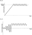
Fig. 4 ] Lafigure 4 est une courbe montrant la position d'un poussoir d'un système de freinage électrique lors d'une consigne de position fixe avec application d'un mouvement oscillant conformément à l'invention, - [
Fig. 5 ] Lafigure 5 est une courbe montrant le courant de phase envoyé dans le ou les bobinages du moteur du poussoir de lafigure 4 . - La
figure 1 illustre un système de freinage électrique 100 qui comprend des freins électromécaniques 50 (un seul étant représentés sur lafigure 1 ) comportant chacun une pile de disques 52 en tant qu'organes de friction. La pile de disques 52 comporte en alternance des disques solidaires en rotation d'une roue à freiner et des disques fixes en rotation. Chaque frein électromécanique 50 comprend en outre une pluralité d'actionneurs 53 (un seul est représenté ici) qui sont portés par une couronne 54 pour s'étendre en regard de la pile de disques 52. Chaque actionneur 53 comporte un poussoir 55 apte à être déplacé vers la pile de disques 52 pour presser celle-ci et ainsi générer un effort de freinage. - Le poussoir 55 est déplacé par un moteur électrique de l'actionneur via une chaîne cinématique transformant un mouvement de rotation du moteur électrique en un mouvement de translation du poussoir 55. Le moteur électrique comprend un ou plusieurs bobinages (non représentés sur la
figure 1 ) qui sont alimentés par un contrôleur 60 comportant un module de puissance 63 qui délivre au(x) bobinage(s) du moteur de l'actionneur des courants de phase IPH en fonction d'un ordre 62 délivré par un module de commande 61. - Les ordres délivrés par le module de commande 61 sont élaborés à partir de divers signaux venant en particulier d'un calculateur de freinage 10, d'une pédale de frein 20 ou d'un sélecteur de parc 30.
- L'ensemble du système de freinage de l'aéronef peut fonctionner typiquement suivant plusieurs modes comme notamment un mode normal, un mode d'urgence, et un mode de parc.
- Par souci de simplification, on ne décrira ici qu'un fonctionnement en mode normal dans lequel le module de commande 61 génère un ordre 62 en fonction d'une consigne de freinage 11 reçue d'un calculateur de freinage 10. La consigne de freinage 11 comprend une consigne de position du moteur de l'actionneur et une consigne d'effort de l'actionneur.
- Conformément à l'invention, le système de freinage électrique comprend en outre des moyens de modulation configurés pour faire varier le courant de phase transmis à chaque bobinage du moteur électrique de manière à faire osciller ledit courant de phase autour du courant de phase de consigne, c'est-à-dire le courant correspondant à la consigne de freinage. La variation d'amplitude du signal de courant alternatif créé autour du courant de phase de consigne est faible en comparaison de la valeur du courant de phase de consigne afin de ne pas perturber l'effort de freinage commandé par la consigne de freinage. De même, la fréquence du signal de courant de phase ainsi modulé est choisie de manière à avoir un effet négligeable du point de vue du freinage. L'amplitude de la modulation autour de la consigne de freinage est de préférence de l'ordre de 0,5%. La fréquence de cette modulation est de préférence inférieure ou égale à 1 hertz.
- Selon une première caractéristique du système et du procédé de l'invention, la modulation du courant de phase est réalisée par application d'un mouvement oscillant autour de la consigne de position de l'actionneur. Dans l'exemple décrit ici, cette modulation est réalisée par un module 40 qui applique un mouvement oscillant autour de la consigne de position présente dans la consigne de freinage 11.
- Les
figures 2 et 3 illustrent respectivement la position du poussoir et le courant de phase transmis au moteur d'un actionneur comme l'actionneur 53 décrit ci-avant en fonction d'une consigne de position sans application d'une modulation autour de la consigne de position. Comme on peut le constater, dès que la position de consigne est atteinte par le poussoir, le ou les bobinages du moteur sont alimentés avec un courant de phase important et continu, et ce durant toute la période d'immobilisation du moteur en position. Cela provoque un échauffement important dans le ou les bobinages du moteur du fait des pertes par effet Joule. - Les
figures 4 et 5 illustrent respectivement la position du poussoir et le courant de phase transmis au moteur d'un actionneur comme l'actionneur 53 décrit ci-avant en fonction d'une consigne de position et avec application d'une modulation autour de la consigne de position. Sur lafigure 4 , on voit que la position du poussoir oscille autour de la position de consigne en réponse à l'application d'un mouvement oscillant sur la consigne de position qui peut être réalisée par exemple par le module 40. Cette oscillation se traduit par une variation du courant de phase de consigne envoyé à chaque bobinage du moteur comme illustré sur lafigure 5 . Le ou les bobinages du moteur de l'actionneur ne sont plus alimentés en courant de façon continue pendant la durée d'immobilisation en position du moteur, ce qui permet d'éviter un échauffement du ou des bobinages. - Selon une deuxième caractéristique du système et du procédé de l'invention, la modulation du courant de phase est réalisée par application d'un mouvement oscillant autour de la consigne d'effort de l'actionneur. Dans l'exemple décrit ici, cette modulation est réalisée par un module 70 qui applique un mouvement oscillant autour de la consigne d'effort présente dans la consigne de freinage 11.
- Comme expliqué ci-avant pour la consigne en position du moteur, dès que l'effort de consigne que doit appliquer l'actionneur sur la pile de disques de freins via le poussoir est atteinte, le ou les bobinages du moteur sont alimentés avec un courant de phase important et continu, et ce durant toute la période d'application de l'effort. Cela provoque un échauffement important dans le ou les bobinages du moteur du fait des pertes par effet Joule.
- Lors de l'application d'une modulation autour de la consigne d'effort, l'effort exercé par le poussoir oscille autour de l'effort de consigne en réponse à l'application d'un mouvement oscillant sur la consigne d'effort qui peut être réalisée par exemple par le module 70. Cette oscillation se traduit par une variation du courant de phase de consigne envoyé à chaque bobinage du moteur. Le ou les bobinages du moteur de l'actionneur ne sont plus alimentés en courant de façon continue pendant la durée d'immobilisation en position du moteur, ce qui permet d'éviter un échauffement du ou des bobinages.
- Selon une troisième caractéristique du système et du procédé de l'invention, la modulation du courant de phase est réalisée par application d'une modulation directement sur le courant de phase de consigne. Cette modulation peut être réalisée par un module 80 qui applique un courant oscillant sur la valeur du courant de phase de consigne. Le ou les bobinages du moteur de l'actionneur ne sont plus alimentés en courant de façon continue pendant la durée d'immobilisation en position du moteur, ce qui permet d'éviter un échauffement du ou des bobinages.
- Concernant les instants ou évènement de déclenchement de la modulation du courant de phase par application d'un mouvement oscillant autour de la consigne de position de l'actionneur, ou par application d'un mouvement oscillant autour de la consigne d'effort de l'actionneur, ou encore par application d'une modulation directement sur le courant de phase de consigne telles que décrites ci-avant, au moins deux options sont possibles.
- Selon une première option, la modulation du courant de phase est mise en œuvre pour toute consigne de freinage non nulle, la modulation du courant de phase étant alors appliquée en permanence.
- Selon une deuxième option, la variation du courant de phase transmis à chaque bobinage du moteur électrique est réalisée en réponse à une détection d'une consigne de freinage comprenant une consigne en position fixe ou une consigne d'effort constant. Les moyens de modulation du courant de phase sont alors configurés pour déclencher la modulation sur détection d'une consigne en position fixe ou une consigne d'effort constant, la modulation du courant de phase étant appliquée seulement dans les cas de consigne de freinage susceptibles de créer un échauffement dans le ou les bobinages du moteur de l'actionneur.
Claims (10)
- Procédé de pilotage d'un système de freinage électrique pour aéronef (100) comprenant une pluralité d'actionneurs électromécaniques (53) aptes à appliquer un effort de freinage sur des organes de friction (52), chaque actionneur électromécanique comprenant un moteur électrique équipé d'un ou plusieurs bobinages, le système de freinage comprenant en outre au moins un module de puissance (63) configuré pour envoyer à chaque bobinage de moteur électrique un courant de phase (IPH) et au moins un module de commande (61) configuré pour commander, en réponse à une consigne de freinage (11), l'envoi par le module de puissance d'un courant de phase de consigne déterminé en fonction de l'effort de freinage à appliquer, caractérisé en ce que le procédé comprend la variation du courant de phase transmis à chaque bobinage du moteur électrique de manière à faire osciller ledit courant de phase autour du courant de phase de consigne.
- Procédé selon la revendication 1, dans lequel la consigne de freinage (11) comprend une consigne de position de chaque actionneur électromécanique (53) et dans lequel la variation du courant de phase (IPH) est réalisée par application d'un mouvement oscillant autour de la consigne de position.
- Procédé selon la revendication 1, dans lequel la consigne de freinage (11) comprend une consigne d'effort de chaque actionneur électromécanique (53) et dans lequel la variation du courant de phase (IPH) est réalisée par application d'un mouvement oscillant autour de la consigne d'effort de l'actionneur.
- Procédé selon la revendication 1, dans lequel la variation du courant de phase (IPH) est réalisée par application d'une modulation directement sur le courant de phase de consigne.
- Procédé selon l'une quelconque des revendications 1 à 4, dans lequel la variation du courant de phase (IPH) transmis à chaque bobinage du moteur électrique est réalisée en réponse à une détection d'une consigne de freinage comprenant une consigne en position fixe ou une consigne d'effort constant.
- Système de freinage électrique pour aéronef (100) comprenant une pluralité d'actionneurs électromécaniques (53) aptes à appliquer un effort de freinage sur des organes de friction (52), chaque actionneur électromécanique comprenant un moteur électrique équipé d'un ou plusieurs bobinages, le système de freinage comprenant en outre au moins un module de puissance (63) configuré pour envoyer à chaque bobinage de moteur électrique un courant de phase (IPH) et au moins un module de commande (61) configuré pour commander, en réponse à une consigne de freinage (11), l'envoi par le module de puissance d'un courant de phase de consigne déterminé en fonction de l'effort de freinage à appliquer, caractérisé en ce que le système comprend des moyens de modulation configurés pour faire varier le courant de phase transmis à chaque bobinage du moteur électrique de manière à faire osciller ledit courant de phase autour du courant de phase de consigne.
- Système selon la revendication 6, dans lequel la consigne de freinage (11) comprend une consigne de position de chaque actionneur électromécanique (53) et dans lequel les moyens de modulation (40) sont configurés pour appliquer un mouvement oscillant autour de la consigne de position.
- Système selon la revendication 6, dans lequel la consigne de freinage (11) comprend une consigne d'effort de chaque actionneur électromécanique (53) et dans lequel les moyens de modulation (70) sont configurés pour appliquer un mouvement oscillant autour de la consigne d'effort de l'actionneur.
- Système selon la revendication 6, dans lequel les moyens de modulation (80) sont configurés pour appliquer une modulation directement sur le courant de phase de consigne.
- Système selon l'une quelconque des revendications 6 à 9, dans lequel les moyens de modulation sont configurés pour faire varier le courant de phase (IPH) transmis à chaque bobinage du moteur électrique en réponse à une détection d'une consigne de freinage comprenant une consigne en position fixe ou une consigne d'effort constant.
Applications Claiming Priority (1)
| Application Number | Priority Date | Filing Date | Title |
|---|---|---|---|
| FR1904730A FR3095792B1 (fr) | 2019-05-06 | 2019-05-06 | Procédé de pilotage d’un système de freinage électrique et système de freinage électrique pour aéronef |
Publications (3)
| Publication Number | Publication Date |
|---|---|
| EP3736185A2 true EP3736185A2 (fr) | 2020-11-11 |
| EP3736185A3 EP3736185A3 (fr) | 2020-11-25 |
| EP3736185B1 EP3736185B1 (fr) | 2022-03-23 |
Family
ID=67875635
Family Applications (1)
| Application Number | Title | Priority Date | Filing Date |
|---|---|---|---|
| EP20169063.3A Active EP3736185B1 (fr) | 2019-05-06 | 2020-04-09 | Procede de pilotage d'un systeme de freinage electrique et systeme de freinage electrique pour aeronef |
Country Status (6)
| Country | Link |
|---|---|
| US (1) | US11447109B2 (fr) |
| EP (1) | EP3736185B1 (fr) |
| CN (1) | CN111891096B (fr) |
| CA (1) | CA3078353A1 (fr) |
| ES (1) | ES2914029T3 (fr) |
| FR (1) | FR3095792B1 (fr) |
Families Citing this family (1)
| Publication number | Priority date | Publication date | Assignee | Title |
|---|---|---|---|---|
| DE102020211522A1 (de) * | 2020-09-14 | 2022-03-17 | Continental Teves Ag & Co. Ohg | Verfahren und System zum automatisierten Einparken eines Fahrzeugs |
Citations (1)
| Publication number | Priority date | Publication date | Assignee | Title |
|---|---|---|---|---|
| EP2544931A1 (fr) | 2010-03-12 | 2013-01-16 | Messier-Bugatti-Dowty | Procede de gestion d'un systeme de freinage pour aeronef equipe de freins electromecaniques |
Family Cites Families (12)
| Publication number | Priority date | Publication date | Assignee | Title |
|---|---|---|---|---|
| GB0421443D0 (en) * | 2004-09-27 | 2004-10-27 | Unsworth Peter | Point on wave (pow) control for motor starting and switching |
| US7467692B2 (en) * | 2005-03-17 | 2008-12-23 | Honeywell International Inc. | Method of and system for reducing power required for an electric brake to maintain a static force |
| US20090009011A1 (en) * | 2006-03-03 | 2009-01-08 | Jonathan Sidney Edelson | Motor using magnetic normal force |
| FR2951330B1 (fr) * | 2009-10-13 | 2013-03-08 | Messier Bugatti | Reseau de pilotage pour actionneurs mono ou multimoteurs, particulierement adapte a des applications aeronautiques telles que l'alimentation de moteurs de boitiers d'accrochage |
| JP6570877B2 (ja) * | 2015-05-22 | 2019-09-04 | Ntn株式会社 | 電動ブレーキ装置 |
| US9783171B2 (en) * | 2015-07-02 | 2017-10-10 | Goodrich Corporation | Electromechanical braking systems and methods with power demand control |
| JP6644502B2 (ja) * | 2015-09-10 | 2020-02-12 | Ntn株式会社 | 電動ブレーキ装置 |
| FR3044296B1 (fr) * | 2015-12-01 | 2017-12-29 | Messier Bugatti Dowty | Architecture de systeme de freinage pour aeronoef. |
| JP6653179B2 (ja) * | 2016-01-14 | 2020-02-26 | Thk株式会社 | リニアモータの制御装置及び制御方法 |
| US10427665B2 (en) * | 2016-03-21 | 2019-10-01 | Simmonds Precision Products, Inc. | Force feedback fault detection and accommodation for a multi-channel electric brake actuator controller |
| JP2018070083A (ja) * | 2016-11-04 | 2018-05-10 | Ntn株式会社 | 電動ブレーキ装置 |
| FR3094313B1 (fr) * | 2019-04-01 | 2024-05-31 | Safran Landing Systems | Système de freinage d’une roue d’aéronef, configurable selon un mode normal ou selon un mode RTO |
-
2019
- 2019-05-06 FR FR1904730A patent/FR3095792B1/fr not_active Expired - Fee Related
-
2020
- 2020-04-09 ES ES20169063T patent/ES2914029T3/es active Active
- 2020-04-09 EP EP20169063.3A patent/EP3736185B1/fr active Active
- 2020-04-20 CA CA3078353A patent/CA3078353A1/fr active Pending
- 2020-04-30 CN CN202010360581.5A patent/CN111891096B/zh active Active
- 2020-05-05 US US16/867,114 patent/US11447109B2/en active Active
Patent Citations (1)
| Publication number | Priority date | Publication date | Assignee | Title |
|---|---|---|---|---|
| EP2544931A1 (fr) | 2010-03-12 | 2013-01-16 | Messier-Bugatti-Dowty | Procede de gestion d'un systeme de freinage pour aeronef equipe de freins electromecaniques |
Also Published As
| Publication number | Publication date |
|---|---|
| CA3078353A1 (fr) | 2020-11-06 |
| US11447109B2 (en) | 2022-09-20 |
| FR3095792A1 (fr) | 2020-11-13 |
| EP3736185A3 (fr) | 2020-11-25 |
| ES2914029T3 (es) | 2022-06-07 |
| US20200353906A1 (en) | 2020-11-12 |
| EP3736185B1 (fr) | 2022-03-23 |
| FR3095792B1 (fr) | 2021-04-16 |
| CN111891096B (zh) | 2023-09-19 |
| CN111891096A (zh) | 2020-11-06 |
Similar Documents
| Publication | Publication Date | Title |
|---|---|---|
| EP2475077B1 (fr) | Actionneur électromécanique à double alimentation | |
| FR2966114A1 (fr) | Systeme de freins de vehicule et procede de gestion d'un tel systeme de freins | |
| EP3736185B1 (fr) | Procede de pilotage d'un systeme de freinage electrique et systeme de freinage electrique pour aeronef | |
| FR2884207A1 (fr) | Procede de freinage d'un vehicule pour un arret de secours et systeme de frein pour la mise en oeuvre du procede | |
| CA2726828C (fr) | Circuit de freinage electrique muni de moyens pour commander les organes de blocage des poussoirs d'actionneurs electromecaniques equipant un frein d'aeronef | |
| FR3095804A1 (fr) | Dispositif d’application d’effort pour manche de pilotage | |
| EP2724907B1 (fr) | Système de freinage électromécanique pour aéronef | |
| FR2768790A1 (fr) | Dispositif d'actionnement d'un frein electromagnetique de vehicule | |
| EP1681220B1 (fr) | Dispositif de protection contre les freinages intempestifs pour un frein à actionneurs électromécaniques | |
| CA3077543C (fr) | Systeme de freinage d'une roue d'aeronef, configurable selon un mode normal ou selon un mode rto | |
| FR2964624A1 (fr) | Systeme de freins de vehicule | |
| EP4172011B1 (fr) | Procédé de freinage amélioré d'un véhicule | |
| WO2019076889A1 (fr) | « dispositif mécatronique pour l'actionnement d'un dispositif de freinage, frein à disque et procédé de freinage associés» | |
| EP1621953A1 (fr) | Moyen de commande de frein de stationnement électrique permettant d'ajuster le niveau de serrage | |
| EP3941790B1 (fr) | Système de commande pour un frein électrique avec assistance hydraulique | |
| FR3023814A1 (fr) | Dispositif de commande de freinage pour vehicule | |
| FR3161464A1 (fr) | Dispositif de freinage a champ magnetique tournant, roue freinee et aeronef correspondant. | |
| FR2966542A1 (fr) | Systeme de freins a disque electrique | |
| FR2822428A1 (fr) | Dispositif de freinage a force de resistance reconstituee | |
| FR3124163A1 (fr) | Compensateur de vol pour aéronef | |
| BE562828A (fr) | ||
| FR2648120A1 (fr) | Dispositif de freinage a pre-reglage et commande automatique pour un fil en deplacement | |
| FR2846620A1 (fr) | Systeme et procede de commande de la force de freinage d'un vehicule automobile. |
Legal Events
| Date | Code | Title | Description |
|---|---|---|---|
| PUAI | Public reference made under article 153(3) epc to a published international application that has entered the european phase |
Free format text: ORIGINAL CODE: 0009012 |
|
| STAA | Information on the status of an ep patent application or granted ep patent |
Free format text: STATUS: REQUEST FOR EXAMINATION WAS MADE |
|
| PUAL | Search report despatched |
Free format text: ORIGINAL CODE: 0009013 |
|
| 17P | Request for examination filed |
Effective date: 20200409 |
|
| AK | Designated contracting states |
Kind code of ref document: A2 Designated state(s): AL AT BE BG CH CY CZ DE DK EE ES FI FR GB GR HR HU IE IS IT LI LT LU LV MC MK MT NL NO PL PT RO RS SE SI SK SM TR |
|
| AX | Request for extension of the european patent |
Extension state: BA ME |
|
| AK | Designated contracting states |
Kind code of ref document: A3 Designated state(s): AL AT BE BG CH CY CZ DE DK EE ES FI FR GB GR HR HU IE IS IT LI LT LU LV MC MK MT NL NO PL PT RO RS SE SI SK SM TR |
|
| AX | Request for extension of the european patent |
Extension state: BA ME |
|
| RIC1 | Information provided on ipc code assigned before grant |
Ipc: B60T 8/17 20060101AFI20201020BHEP Ipc: B60T 8/32 20060101ALI20201020BHEP |
|
| GRAP | Despatch of communication of intention to grant a patent |
Free format text: ORIGINAL CODE: EPIDOSNIGR1 |
|
| STAA | Information on the status of an ep patent application or granted ep patent |
Free format text: STATUS: GRANT OF PATENT IS INTENDED |
|
| INTG | Intention to grant announced |
Effective date: 20211117 |
|
| GRAS | Grant fee paid |
Free format text: ORIGINAL CODE: EPIDOSNIGR3 |
|
| GRAA | (expected) grant |
Free format text: ORIGINAL CODE: 0009210 |
|
| STAA | Information on the status of an ep patent application or granted ep patent |
Free format text: STATUS: THE PATENT HAS BEEN GRANTED |
|
| AK | Designated contracting states |
Kind code of ref document: B1 Designated state(s): AL AT BE BG CH CY CZ DE DK EE ES FI FR GB GR HR HU IE IS IT LI LT LU LV MC MK MT NL NO PL PT RO RS SE SI SK SM TR |
|
| REG | Reference to a national code |
Ref country code: GB Ref legal event code: FG4D Free format text: NOT ENGLISH |
|
| REG | Reference to a national code |
Ref country code: CH Ref legal event code: EP |
|
| REG | Reference to a national code |
Ref country code: IE Ref legal event code: FG4D Free format text: LANGUAGE OF EP DOCUMENT: FRENCH |
|
| REG | Reference to a national code |
Ref country code: DE Ref legal event code: R096 Ref document number: 602020002279 Country of ref document: DE |
|
| REG | Reference to a national code |
Ref country code: AT Ref legal event code: REF Ref document number: 1477240 Country of ref document: AT Kind code of ref document: T Effective date: 20220415 |
|
| REG | Reference to a national code |
Ref country code: ES Ref legal event code: FG2A Ref document number: 2914029 Country of ref document: ES Kind code of ref document: T3 Effective date: 20220607 |
|
| REG | Reference to a national code |
Ref country code: LT Ref legal event code: MG9D |
|
| REG | Reference to a national code |
Ref country code: NL Ref legal event code: MP Effective date: 20220323 |
|
| PG25 | Lapsed in a contracting state [announced via postgrant information from national office to epo] |
Ref country code: SE Free format text: LAPSE BECAUSE OF FAILURE TO SUBMIT A TRANSLATION OF THE DESCRIPTION OR TO PAY THE FEE WITHIN THE PRESCRIBED TIME-LIMIT Effective date: 20220323 Ref country code: RS Free format text: LAPSE BECAUSE OF FAILURE TO SUBMIT A TRANSLATION OF THE DESCRIPTION OR TO PAY THE FEE WITHIN THE PRESCRIBED TIME-LIMIT Effective date: 20220323 Ref country code: NO Free format text: LAPSE BECAUSE OF FAILURE TO SUBMIT A TRANSLATION OF THE DESCRIPTION OR TO PAY THE FEE WITHIN THE PRESCRIBED TIME-LIMIT Effective date: 20220623 Ref country code: LT Free format text: LAPSE BECAUSE OF FAILURE TO SUBMIT A TRANSLATION OF THE DESCRIPTION OR TO PAY THE FEE WITHIN THE PRESCRIBED TIME-LIMIT Effective date: 20220323 Ref country code: HR Free format text: LAPSE BECAUSE OF FAILURE TO SUBMIT A TRANSLATION OF THE DESCRIPTION OR TO PAY THE FEE WITHIN THE PRESCRIBED TIME-LIMIT Effective date: 20220323 Ref country code: BG Free format text: LAPSE BECAUSE OF FAILURE TO SUBMIT A TRANSLATION OF THE DESCRIPTION OR TO PAY THE FEE WITHIN THE PRESCRIBED TIME-LIMIT Effective date: 20220623 |
|
| REG | Reference to a national code |
Ref country code: AT Ref legal event code: MK05 Ref document number: 1477240 Country of ref document: AT Kind code of ref document: T Effective date: 20220323 |
|
| PG25 | Lapsed in a contracting state [announced via postgrant information from national office to epo] |
Ref country code: LV Free format text: LAPSE BECAUSE OF FAILURE TO SUBMIT A TRANSLATION OF THE DESCRIPTION OR TO PAY THE FEE WITHIN THE PRESCRIBED TIME-LIMIT Effective date: 20220323 Ref country code: GR Free format text: LAPSE BECAUSE OF FAILURE TO SUBMIT A TRANSLATION OF THE DESCRIPTION OR TO PAY THE FEE WITHIN THE PRESCRIBED TIME-LIMIT Effective date: 20220624 Ref country code: FI Free format text: LAPSE BECAUSE OF FAILURE TO SUBMIT A TRANSLATION OF THE DESCRIPTION OR TO PAY THE FEE WITHIN THE PRESCRIBED TIME-LIMIT Effective date: 20220323 |
|
| PG25 | Lapsed in a contracting state [announced via postgrant information from national office to epo] |
Ref country code: NL Free format text: LAPSE BECAUSE OF FAILURE TO SUBMIT A TRANSLATION OF THE DESCRIPTION OR TO PAY THE FEE WITHIN THE PRESCRIBED TIME-LIMIT Effective date: 20220323 |
|
| PG25 | Lapsed in a contracting state [announced via postgrant information from national office to epo] |
Ref country code: SM Free format text: LAPSE BECAUSE OF FAILURE TO SUBMIT A TRANSLATION OF THE DESCRIPTION OR TO PAY THE FEE WITHIN THE PRESCRIBED TIME-LIMIT Effective date: 20220323 Ref country code: SK Free format text: LAPSE BECAUSE OF FAILURE TO SUBMIT A TRANSLATION OF THE DESCRIPTION OR TO PAY THE FEE WITHIN THE PRESCRIBED TIME-LIMIT Effective date: 20220323 Ref country code: RO Free format text: LAPSE BECAUSE OF FAILURE TO SUBMIT A TRANSLATION OF THE DESCRIPTION OR TO PAY THE FEE WITHIN THE PRESCRIBED TIME-LIMIT Effective date: 20220323 Ref country code: PT Free format text: LAPSE BECAUSE OF FAILURE TO SUBMIT A TRANSLATION OF THE DESCRIPTION OR TO PAY THE FEE WITHIN THE PRESCRIBED TIME-LIMIT Effective date: 20220725 Ref country code: EE Free format text: LAPSE BECAUSE OF FAILURE TO SUBMIT A TRANSLATION OF THE DESCRIPTION OR TO PAY THE FEE WITHIN THE PRESCRIBED TIME-LIMIT Effective date: 20220323 Ref country code: CZ Free format text: LAPSE BECAUSE OF FAILURE TO SUBMIT A TRANSLATION OF THE DESCRIPTION OR TO PAY THE FEE WITHIN THE PRESCRIBED TIME-LIMIT Effective date: 20220323 Ref country code: AT Free format text: LAPSE BECAUSE OF FAILURE TO SUBMIT A TRANSLATION OF THE DESCRIPTION OR TO PAY THE FEE WITHIN THE PRESCRIBED TIME-LIMIT Effective date: 20220323 |
|
| PG25 | Lapsed in a contracting state [announced via postgrant information from national office to epo] |
Ref country code: PL Free format text: LAPSE BECAUSE OF FAILURE TO SUBMIT A TRANSLATION OF THE DESCRIPTION OR TO PAY THE FEE WITHIN THE PRESCRIBED TIME-LIMIT Effective date: 20220323 Ref country code: IS Free format text: LAPSE BECAUSE OF FAILURE TO SUBMIT A TRANSLATION OF THE DESCRIPTION OR TO PAY THE FEE WITHIN THE PRESCRIBED TIME-LIMIT Effective date: 20220723 Ref country code: AL Free format text: LAPSE BECAUSE OF FAILURE TO SUBMIT A TRANSLATION OF THE DESCRIPTION OR TO PAY THE FEE WITHIN THE PRESCRIBED TIME-LIMIT Effective date: 20220323 |
|
| REG | Reference to a national code |
Ref country code: DE Ref legal event code: R097 Ref document number: 602020002279 Country of ref document: DE |
|
| REG | Reference to a national code |
Ref country code: BE Ref legal event code: MM Effective date: 20220430 |
|
| PLBE | No opposition filed within time limit |
Free format text: ORIGINAL CODE: 0009261 |
|
| STAA | Information on the status of an ep patent application or granted ep patent |
Free format text: STATUS: NO OPPOSITION FILED WITHIN TIME LIMIT |
|
| PG25 | Lapsed in a contracting state [announced via postgrant information from national office to epo] |
Ref country code: MC Free format text: LAPSE BECAUSE OF FAILURE TO SUBMIT A TRANSLATION OF THE DESCRIPTION OR TO PAY THE FEE WITHIN THE PRESCRIBED TIME-LIMIT Effective date: 20220323 Ref country code: LU Free format text: LAPSE BECAUSE OF NON-PAYMENT OF DUE FEES Effective date: 20220409 Ref country code: DK Free format text: LAPSE BECAUSE OF FAILURE TO SUBMIT A TRANSLATION OF THE DESCRIPTION OR TO PAY THE FEE WITHIN THE PRESCRIBED TIME-LIMIT Effective date: 20220323 |
|
| PG25 | Lapsed in a contracting state [announced via postgrant information from national office to epo] |
Ref country code: BE Free format text: LAPSE BECAUSE OF NON-PAYMENT OF DUE FEES Effective date: 20220430 |
|
| 26N | No opposition filed |
Effective date: 20230102 |
|
| PG25 | Lapsed in a contracting state [announced via postgrant information from national office to epo] |
Ref country code: IE Free format text: LAPSE BECAUSE OF NON-PAYMENT OF DUE FEES Effective date: 20220409 |
|
| PG25 | Lapsed in a contracting state [announced via postgrant information from national office to epo] |
Ref country code: SI Free format text: LAPSE BECAUSE OF FAILURE TO SUBMIT A TRANSLATION OF THE DESCRIPTION OR TO PAY THE FEE WITHIN THE PRESCRIBED TIME-LIMIT Effective date: 20220323 |
|
| REG | Reference to a national code |
Ref country code: CH Ref legal event code: PL |
|
| PG25 | Lapsed in a contracting state [announced via postgrant information from national office to epo] |
Ref country code: LI Free format text: LAPSE BECAUSE OF NON-PAYMENT OF DUE FEES Effective date: 20230430 Ref country code: CH Free format text: LAPSE BECAUSE OF NON-PAYMENT OF DUE FEES Effective date: 20230430 |
|
| PG25 | Lapsed in a contracting state [announced via postgrant information from national office to epo] |
Ref country code: MK Free format text: LAPSE BECAUSE OF FAILURE TO SUBMIT A TRANSLATION OF THE DESCRIPTION OR TO PAY THE FEE WITHIN THE PRESCRIBED TIME-LIMIT Effective date: 20220323 Ref country code: CY Free format text: LAPSE BECAUSE OF FAILURE TO SUBMIT A TRANSLATION OF THE DESCRIPTION OR TO PAY THE FEE WITHIN THE PRESCRIBED TIME-LIMIT Effective date: 20220323 |
|
| PG25 | Lapsed in a contracting state [announced via postgrant information from national office to epo] |
Ref country code: HU Free format text: LAPSE BECAUSE OF FAILURE TO SUBMIT A TRANSLATION OF THE DESCRIPTION OR TO PAY THE FEE WITHIN THE PRESCRIBED TIME-LIMIT; INVALID AB INITIO Effective date: 20200409 |
|
| PG25 | Lapsed in a contracting state [announced via postgrant information from national office to epo] |
Ref country code: MT Free format text: LAPSE BECAUSE OF FAILURE TO SUBMIT A TRANSLATION OF THE DESCRIPTION OR TO PAY THE FEE WITHIN THE PRESCRIBED TIME-LIMIT Effective date: 20220323 |
|
| PGFP | Annual fee paid to national office [announced via postgrant information from national office to epo] |
Ref country code: DE Payment date: 20250417 Year of fee payment: 6 |
|
| PGFP | Annual fee paid to national office [announced via postgrant information from national office to epo] |
Ref country code: GB Payment date: 20250424 Year of fee payment: 6 Ref country code: ES Payment date: 20250519 Year of fee payment: 6 |
|
| PGFP | Annual fee paid to national office [announced via postgrant information from national office to epo] |
Ref country code: IT Payment date: 20250430 Year of fee payment: 6 |
|
| PGFP | Annual fee paid to national office [announced via postgrant information from national office to epo] |
Ref country code: FR Payment date: 20250422 Year of fee payment: 6 |
|
| PG25 | Lapsed in a contracting state [announced via postgrant information from national office to epo] |
Ref country code: TR Free format text: LAPSE BECAUSE OF FAILURE TO SUBMIT A TRANSLATION OF THE DESCRIPTION OR TO PAY THE FEE WITHIN THE PRESCRIBED TIME-LIMIT Effective date: 20220323 |