EP3736219A1 - Dispositif de dépliage, méthode et système correspondante - Google Patents
Dispositif de dépliage, méthode et système correspondante Download PDFInfo
- Publication number
- EP3736219A1 EP3736219A1 EP20177476.7A EP20177476A EP3736219A1 EP 3736219 A1 EP3736219 A1 EP 3736219A1 EP 20177476 A EP20177476 A EP 20177476A EP 3736219 A1 EP3736219 A1 EP 3736219A1
- Authority
- EP
- European Patent Office
- Prior art keywords
- packaging
- transport
- section
- packaging section
- holding
- Prior art date
- Legal status (The legal status is an assumption and is not a legal conclusion. Google has not performed a legal analysis and makes no representation as to the accuracy of the status listed.)
- Granted
Links
Images









Classifications
-
- B—PERFORMING OPERATIONS; TRANSPORTING
- B65—CONVEYING; PACKING; STORING; HANDLING THIN OR FILAMENTARY MATERIAL
- B65B—MACHINES, APPARATUS OR DEVICES FOR, OR METHODS OF, PACKAGING ARTICLES OR MATERIALS; UNPACKING
- B65B69/00—Unpacking of articles or materials, not otherwise provided for
- B65B69/0008—Opening and emptying bags
-
- B—PERFORMING OPERATIONS; TRANSPORTING
- B65—CONVEYING; PACKING; STORING; HANDLING THIN OR FILAMENTARY MATERIAL
- B65B—MACHINES, APPARATUS OR DEVICES FOR, OR METHODS OF, PACKAGING ARTICLES OR MATERIALS; UNPACKING
- B65B69/00—Unpacking of articles or materials, not otherwise provided for
- B65B69/0033—Unpacking of articles or materials, not otherwise provided for by cutting
-
- B—PERFORMING OPERATIONS; TRANSPORTING
- B65—CONVEYING; PACKING; STORING; HANDLING THIN OR FILAMENTARY MATERIAL
- B65B—MACHINES, APPARATUS OR DEVICES FOR, OR METHODS OF, PACKAGING ARTICLES OR MATERIALS; UNPACKING
- B65B69/00—Unpacking of articles or materials, not otherwise provided for
- B65B69/0033—Unpacking of articles or materials, not otherwise provided for by cutting
- B65B69/0041—Unpacking of articles or materials, not otherwise provided for by cutting by puncturing
-
- B—PERFORMING OPERATIONS; TRANSPORTING
- B29—WORKING OF PLASTICS; WORKING OF SUBSTANCES IN A PLASTIC STATE IN GENERAL
- B29C—SHAPING OR JOINING OF PLASTICS; SHAPING OF MATERIAL IN A PLASTIC STATE, NOT OTHERWISE PROVIDED FOR; AFTER-TREATMENT OF THE SHAPED PRODUCTS, e.g. REPAIRING
- B29C55/00—Shaping by stretching, e.g. drawing through a die; Apparatus therefor
- B29C55/02—Shaping by stretching, e.g. drawing through a die; Apparatus therefor of plates or sheets
- B29C55/18—Shaping by stretching, e.g. drawing through a die; Apparatus therefor of plates or sheets by squeezing between surfaces, e.g. rollers
-
- B—PERFORMING OPERATIONS; TRANSPORTING
- B65—CONVEYING; PACKING; STORING; HANDLING THIN OR FILAMENTARY MATERIAL
- B65B—MACHINES, APPARATUS OR DEVICES FOR, OR METHODS OF, PACKAGING ARTICLES OR MATERIALS; UNPACKING
- B65B11/00—Wrapping, e.g. partially or wholly enclosing, articles or quantities of material, in strips, sheets or blanks, of flexible material
- B65B2011/002—Prestretching mechanism in wrapping machines
Definitions
- the present invention relates to a stretching device for stretching a packaging, in particular a bag, for an object, in particular a pharmaceutical or cosmetic object, the packaging having a protruding packaging section, the stretching device being a transport device for transporting the object in a transport direction, a holding device for Holding the protruding packaging section, and having a moving device for moving the object. Furthermore, the present invention relates to an unfolding device for unfolding a packaging section of a packaging, in particular a bag, for an object, in particular a pharmaceutical or cosmetic object, the packaging section initially being folded in between a transport device and the packaging. The present invention also relates to an unpacking system which has an unfolding device and a stretching device. Furthermore concerns the present invention a filling system with an unpacking system.
- the present invention also relates to a method for stretching a package, in particular a bag, for an object, in particular a pharmaceutical or cosmetic object.
- the present invention also relates to a method for unfolding a packaging section of a package, in particular a bag, for an object, in particular a pharmaceutical or cosmetic object.
- the present invention also relates to a method for unpacking an object from a package.
- the document shows WO 2011/012658 A1 an opening device for flexible packaging of goods, in particular bottled goods, the opening device having a positioning device for the packaging area to be opened, a detection device and a separating device.
- the detection device has a suction device and a clamping device.
- the positioning device has a slide and at least one stop element in order to fix the packaged piece goods in its position and to bring the packaging into a position that is favorable for the separation process.
- the packaging is gripped on the front by the suction device and fixed with the clamping device.
- the detection device is spaced apart from the stop of the retained package by a backward movement. As a result, the captured packaging area is pulled against the stop and tightened, forming a gusset.
- the cutting device can contain a cutting tool, for example a laser head, a cutting tool or a thermal cutting method.
- the separating device separates the formed gusset of the packaging, while the detection device keeps the gusset pretensioned.
- the publication also shows DE 10 2007 027 878 A1 a device and a method for removing a sterile object from a sterile packaging.
- the device comprises a transport device, a clamping device, a cutting device, a holding device and a removal device.
- sterile objects are transported in sterile packaging, the sterile packaging having a packaging section protruding on one longitudinal side with respect to the transport direction.
- the clamping device is arranged to the side of the transport device and is designed to clamp the protruding packaging section.
- the clamping device has two clamping rollers which are arranged parallel to the transport device and which can be moved relative to one another.
- the cutting device is designed in such a way that it partially cuts the protruding packaging section clamped with the clamping device parallel to the transport device.
- a continuous slot is created in the sterile packaging.
- the holding device holds a second partial area of the sterile packaging.
- the removal device is designed to remove the object from the sterile packaging through the slot.
- a stretching device for stretching a packaging, in particular a bag, for an object, in particular a pharmaceutical or cosmetic object, the packaging having a protruding packaging section.
- the stretching device has a transport device for transporting the object in a transport direction, a Holding device for holding the protruding packaging section, and a moving device for moving the object.
- the holding device has at least two rollers which are arranged perpendicular to the transport direction and are designed to hold the protruding packaging section between them.
- the movement device and / or the holding device are designed to be movable parallel to the transport direction in order to move the object and the holding device away from one another.
- the object is transported on the transport device.
- the direction of transport of the object corresponds to the direction of movement of the object on the transport device.
- upstream and downstream are thus to be understood with regard to the direction of transport.
- long side and front side are also to be understood in relation to the direction of transport.
- a “long side” is arranged essentially parallel to the transport direction.
- one end face is arranged essentially perpendicular to the transport direction.
- the spatial arrangement of elements is specified below relative to the transport device and the packaging transported on the transport device or the object transported on the transport device.
- the packaging has a longitudinal side facing the transport device and a longitudinal side facing away from the transport device.
- the transport device also has a side facing the packaging / the object and a side facing away from the packaging / the object. Accordingly, elements can be arranged on the side of the transport device facing the packaging / the object or on the side of the transport device facing away from the packaging / the object.
- the packaging is stretched on the end. Since the rollers are arranged perpendicular to the transport direction, they cover a part of the packaging section which is arranged on an end face of the packaging. As a result, the packaging is stretched parallel to the transport direction and on the front side of the packaging.
- subsequent devices of an unpacking system such as a severing device for severing the stretched packaging section and a removal device for removing the object from the packaging, can also be arranged in the transport direction without the need for additional repositioning of the wrapped object is required.
- an unfolding device for unfolding a packaging section of a packaging, in particular a bag, for an object, in particular a pharmaceutical or cosmetic object.
- the unfolding device has a transport device for transporting the object in a transport direction, a lifting device for lifting the object, a holding device for holding a region of the packaging adjacent to the packaging section, and a holding device drive device for moving the holding device in a direction pointing away from the packaging section .
- the packaging section is connected on one side to the packaging at a connection point and extends along the packaging from the connection point to an area on the longitudinal side of the packaging facing or facing away from the transport device.
- the area adjacent to the packaging section is to be understood as an area of the packaging which adjoins the joint between the packaging section and the packaging and extends away from the packaging section.
- the packaging section can initially be partially arranged between the longitudinal side facing the transport device and the side of the transport device facing the packaging and is thereby folded in between the transport device and the packaging.
- the connection point can be arranged on an end face of the packaging.
- the packaging section can then extend from the connection point to the transport device to between the transport device and the longitudinal side of the packaging facing the transport device.
- a region of the end face which is located on the side of the connection point facing away from the transport device and a region of the longitudinal side facing away from the transport device corresponds to a region of the packaging which is adjacent to the packaging section.
- the connection point can also be arranged on the edge between an end face and the longitudinal side facing the transport device. In this case, the end face corresponds to an area adjacent to the packaging section.
- connection point can also be arranged on the edge between an end face and the longitudinal side facing away from the transport device.
- the longitudinal side facing away from the transport device corresponds to an area adjacent to the packaging section.
- connection point can also be arranged on the longitudinal side facing away from the transport device or on the longitudinal side facing the transport device. The corresponding adjacent area then corresponds to the area of the packaging which extends away from the connection point from the packaging section.
- the packaging section is pulled out of its folded-in position between the longitudinal side of the packaging facing the transport device and the transport device and is thus folded out.
- the adjacent area can be pulled until the packaging section is completely unfolded and is arranged in a desired position.
- the packaging section extends preferably parallel to the transport device, in particular parallel to the transport direction, and away from the packaging, in particular from the connection point.
- the packaging section is initially partially folded onto the longitudinal side of the packaging facing away from the transport device.
- the connection point can be arranged on an end face of the packaging.
- the packaging section can then extend from the connection point away from the transport device up to the longitudinal side of the packaging facing away from the transport device.
- the adjacent area is arranged on the side of the connection point facing the transport device.
- a stretching device can, for example, more easily grasp and stretch the packaging section.
- an unfolding device for unfolding a packaging section of a packaging, in particular a bag, for an object, in particular a pharmaceutical or cosmetic object.
- the unfolding device has a transport device for transporting the object in one transport direction, a lifting device for lifting the object, and a stop device.
- the stop device has at least one roller arranged perpendicular to the transport direction, which is arranged on the side of the packaging facing away from or facing the transport device and forms a stop for the folded-in packaging section.
- the lifting device and / or the stop device are designed to be movable parallel to the transport direction in order to move the object and the stop device relative to one another.
- a stretching device can, for example, more easily grasp and stretch the packaging section.
- an unpacking system with a stretching device according to the first aspect of the invention or one of its configurations and with an unfolding device according to the third or fifth aspect of the invention or one of its configurations is proposed.
- a packaging section that is initially folded in is unfolded and then stretched.
- the individual components of the stretching device and the folding device are arranged in a compact and space-saving manner.
- a compact arrangement of the subsequent handling devices such as a separation device and / or a removal device, is made possible.
- an unpacking system for unpacking a packaging, in particular a bag, for an object, in particular a pharmaceutical or cosmetic object is proposed, the packaging having a protruding packaging section which is arranged on an upstream end face of the packaging.
- the unpacking system has a transport device for transporting the object in a transport direction and a holding device for holding the protruding packaging section.
- the holding device has at least two rollers which are arranged perpendicular to the transport direction and are designed to fold out and / or stretch the protruding packaging section.
- the packaged objects must be unpacked before further processing, for example filling or decanting in a filling station.
- the unpacking system described provides a simple and compact solution for this, which can also be implemented in tight spaces.
- the protruding packaging section is arranged on one of the end faces of the packaging with respect to the transport direction, in particular wherein the packaging section is arranged on a downstream end face with respect to the transport direction.
- the frontal arrangement of the protruding packaging section can prevent the protruding packaging section from protruding laterally beyond the width of the transport device. This in particular prevents the protruding packaging section from getting caught on structural components or objects which are arranged to the side of the transport device.
- the protruding packaging section protrudes from the packaging essentially parallel to the transport direction.
- the movement device is designed such that it holds the packaging on at least one longitudinal side.
- the object can be in contact with the movement device, for example, with its longitudinal side facing the transport device, in particular be arranged on the movement device. If the object is sufficiently heavy, the static friction is sufficient to move the object with the packaging away from the holding device holding the packaging section for stretching without the packaging overcoming the static friction and reducing the tensile force exerted, for example by sliding on the moving device , or is stopped completely, for example when the object leaves the movement device, in particular if the object falls off the movement device. Furthermore, the movement device can hold the object on two or more sides, for example by means of a clamping force which is exerted on two opposite longitudinal sides. The clamping force should be selected to be sufficiently large to stretch the packaging.
- the movement device is arranged on the side of the transport device facing away from the packaging.
- the movement device has at least one clamping device or suction device for holding the packaging.
- the packaging is fixed on the moving device by the clamping device or the suction device.
- forces act which are directed essentially parallel to the transport direction.
- the clamping device or the suction device are provided in particular so that the object remains fixed in its position on the movement device and cannot slide in the opposite direction to the direction of movement of the movement device due to tensile force occurring during the stretching process.
- the packaging is held on the moving device purely mechanically by friction, that is to say in particular due to the weight of the object which presses the packaging against the transport device.
- the at least two rollers are arranged parallel to one another.
- the protruding packaging section is to be arranged between the two rollers for stretching. If the two rollers are arranged in parallel, placing the protruding packaging section between the two rollers is simplified.
- the at least two rollers are arranged downstream of the movement device, the movement device being designed to move the object in the opposite direction to the transport direction and away from the holding device.
- the objects are usually transported in one transport direction on a transport device both in the packed and in the unpacked state. It is therefore advantageous if the objects can be removed from the packaging in the direction of transport. If the protruding packaging section is now stretched in the transport direction, in particular with the packaging section being arranged on a downstream end face of the packaging, the subsequent work steps, such as opening the packaging, are facilitated, since this allows the packaging to be opened on the downstream end face without the packaging and the object would have to be rotated on the transport device.
- the at least two rollers are rotatably mounted.
- the protruding packaging section is arranged for stretching between the at least two rollers so that the at least two rollers can hold the protruding packaging section.
- the at least two rollers are designed to pull the protruding packaging section between them.
- the rollers can then be moved in such a way that they convey the packaging section into the correct position between them. In particular, this further simplifies the arrangement of the protruding packaging section between the rollers.
- the holding device has a roller rotation drive device for rotating the at least two rollers.
- the roll rotation drive device can drive the rolls so that they draw the protruding packaging portion between them. In particular, this further simplifies the arrangement of the protruding packaging section between the rollers.
- roller rotation drive device is designed to rotate the at least two rollers in the opposite running direction.
- the opposite rotation of the rollers makes it easier to pull in the protruding packaging section between the rollers.
- the holding device preferably has exactly two rollers, the precisely two rollers being driven by the roller rotation drive device in the opposite running direction.
- the at least two rollers are movable relative to one another, in particular the two rollers being designed to clamp the protruding packaging section between them.
- the distance between the rollers can be variably adjusted. It is advantageous if the relative distance between the rollers is large when the protruding packaging section is inserted between the rollers. As soon as the protruding packaging section is arranged between the rolls, the relative distance between the rolls can be reduced in such a way that the protruding packaging section is clamped between the rolls.
- the holding device has a roller translation drive device for moving the at least two rollers.
- roller translation drive device moves the rollers relative to one another.
- the roller translation drive device can therefore set the relative spacing of the rollers from one another as desired.
- the holding device is designed such that it holds the packaging on a longitudinal side facing away from the transport device.
- the packaging section is initially folded in between the transport device and a longitudinal side of the packaging facing the transport device. If the holding device now grips the packaging on the longitudinal side facing away from the transport device and pulls the packaging in a direction pointing away from the packaging section, the packaging section is opened in a simple manner.
- the packaging section is preferably connected to the rest of the packaging on a downstream end face of the packaging. As a result, the packaging section is in an unfolded state from the downstream end face of the packaging from.
- the holding device preferably holds the packaging in a downstream region of the longitudinal side of the packaging facing away from the transport device. To unfold, the holding device is then moved to an upstream region of the longitudinal side facing away from the transport device.
- the holding device is arranged on the side of the transport device facing the object.
- the holding device By arranging the holding device on the side of the transport device facing the object, the space requirement of the unfolding device is reduced to the side of the transport device.
- the holding device has at least one clamping device or suction device for holding the packaging.
- a clamping device or a suction device can be used to easily hold the packaging in an adjacent area.
- the holding device preferably has a suction device.
- the holding device can be moved parallel to the transport direction, in particular to unfold the packaging section, in particular wherein the holding device drive device (68) is designed to hold the holding device parallel, in particular opposite to move to the transport direction (20).
- the packaging section is arranged on one of the front sides of the packaging and, starting from the connection point on the front side, is folded in between the transport device and the longitudinal side facing the transport device, a tensile force in or against the transport direction, i.e. parallel to the transport direction, is which engages the longitudinal side facing away from the transport device, is required to unfold the packaging section.
- the lifting device is arranged on the side of the transport device facing away from the packaging.
- the lifting device only has to be designed in such a way that it engages and lifts the object including the packaging on the longitudinal side facing the transport device. Clamping, gripping or holding the packaging and the object can be advantageous, but is not absolutely necessary if the static friction between the packaging and the lifting device is large enough. Furthermore, with such an arrangement of the lifting device on the side of the transport device facing away from the packaging, the space requirement on the side of the transport device is reduced.
- a transport plane of the transport device has at least one recess, the lifting device being designed to reach through the recess in order to lift the object.
- the lifting device is designed to lift the transport device, in particular a transport plane of the transport device, at least in the support area of the packaging on the transport plane in order to lift the object.
- the lifting device is designed such that it holds the packaging on at least one longitudinal side.
- the holding device holds the packaging during the unfolding operation and is moved in a direction away from the packaging section, it can be advantageous for the lifting device to hold the packaging so that the object does not move on the lifting device during unfolding.
- the lifting device has at least one clamping device or a suction device for holding the packaging.
- the packaging is fixed on the lifting device by the clamping device or the suction device.
- forces act which are directed essentially parallel to the transport direction.
- the clamping device or the suction device are in particular provided so that the object remains fixed in its position on the lifting device and cannot slip in the direction of movement of the holding device due to tensile forces occurring in the opening process.
- the stop device has exactly two rollers, a first roller of the two rollers on the longitudinal side of the packaging facing the transport device and a second roller of the two rollers on that of the transport device facing away from the long side of the packaging is arranged.
- the protruding packaging section either faces the side facing the transport device or faces away on the transport device Side of the packaging is folded.
- the arrangement of one roller each on the side of the packaging facing the transport device and on the side of the packaging facing away from the transport device ensures that one roller can always form a stop for the protruding and folded-in packaging section.
- rollers can be moved relative to one another.
- the two rollers can initially be spaced so far that the packaging can be passed between the rollers.
- the rolls can then be placed against the packaging and roll off the contour in the longitudinal direction of the packaging, thereby completely unfolding the folded-in packaging section and aligning it in the longitudinal direction.
- the lifting device has a horizontal drive which is designed to move the lifting device parallel to the transport direction, in particular opposite to the transport direction.
- the lifting device By moving the lifting device parallel to the transport direction, the object and the packaging are moved parallel to the transport direction. If the folded packaging section lies against the roll, it is unfolded by such a movement.
- the objects are usually transported in one transport direction on a transport device both in the packed and in the unpacked state. It is therefore advantageous if the objects can be removed from the packaging in the direction of transport. It is therefore advantageous if the packaging section is arranged on a downstream end face, is folded out by a movement of the lifting device opposite to the transport direction and thus protrudes downstream. This enables the package to be opened at a downstream end of the package.
- the transport device is designed to transport the object from the unfolding device to the stretching device.
- the unfolding device and the stretching device are usually arranged one after the other downstream, but do not necessarily have to be directly consecutive.
- the two devices can thus be arranged spatially spaced from one another. It can therefore be advantageous for the transport device to transport the packaging with the packaging section folded out to the stretching device.
- the unpacking system has first carrier holders which can be moved perpendicularly and parallel to the transport direction and which form the lifting device and the moving device.
- the unfolding device and the stretching device can be arranged as close to one another as possible, in particular with the two devices being arranged at the same location. It can therefore be advantageous that a movable carrier holder forms both the lifting device of the unfolding device and the movement device of the stretching device. This makes it possible to arrange the unfolding device and the stretching device as close to one another as possible.
- the unpacking system has second carrier holders which can be moved perpendicularly and parallel to the transport direction and which form the holding device and the stop device.
- the rollers can be brought into contact with both sides of the packaging, one of the two rollers forming a stop for the folded-in packaging section.
- the packaging section can be unfolded by a relative movement of the carrier holder and the object.
- the rollers can then hold the protruding packaging section and stretch it by a further relative movement or by being drawn in between the rollers.
- the transport device has a first deflection section in front of the unfolding device, which causes a first change in direction of the transport direction, in particular the first change in direction being 90 °.
- the transport device therefore preferably has deflection sections which cause a change in the direction of transport.
- the changes in direction can assume any value. In order to achieve the most symmetrical arrangement of all components with respect to one another, it is advantageous that the changes in direction are essentially 90 °.
- the unpacking system furthermore has a separating device for completely separating the protruding and stretched packaging section from the packaging.
- the severing device is arranged downstream of the stretching device.
- the packaging section protrudes and is stretched, whereby the packaging section in particular protrudes far from the packaging, the severing of the packaging section is facilitated by a severing device.
- the severing device can have a holding device for holding the protruding and stretched packaging section in order to hold the packaging section during the severing.
- this holding device is not absolutely necessary since the packaging section protrudes far from the packaging due to the stretching process.
- the separating device can preferably be arranged perpendicular to the transport direction.
- the severing device has a cutting knife, a laser or a thermal severing method for completely severing the packaging section.
- a separate holding device can be advantageous if the separated packaging section is specifically disposed of by means of the holding device.
- the separating device has a removal device for removing the object from the packaging.
- the removal device can have holding means, for example a clamping device, for holding the packaging, in particular on a side opposite the opened side of the packaging.
- the removal device can furthermore have a gripping device for removing the object from the packaging.
- the packaging can be pulled away from the object by means of a gripping device in order to remove the packaging from the object.
- the separation device is a disposal device which is designed to dispose of the severed packaging portion and the remainder of the packaging.
- the disposal device can have one or more grippers which move the packaging parts away from the separating device.
- the disposal device can also have a conveyor belt or some other transport device that transports the packaging residues away from the separating device.
- grippers can be designed to place the packaging remains on the conveyor belt.
- the disposal device could also be designed by means of a suction device which sucks in the packaging residues and thus transports them away from the separating device.
- the transport device is designed to transport the object from the stretching device to the severing device, in particular wherein the transporting device has a second deflection section between the stretching device and the severing device , which causes a second change in direction of the transport direction, in particular where the second change in direction is 90 °.
- the stretching device and the severing device can be advantageous to place the stretching device and the severing device spatially separate from one another. This makes it necessary for the objects together with their packaging to be moved from the stretching device to the severing device.
- One possibility of transporting the object from the stretching device to the severing device is provided by the transport device, which can run between the stretching device and the severing device.
- the severing device and the stretching device can be arranged at an angle to one another with respect to the transport direction. This is particularly important when the available space is limited, for example in an industrial hall in which the packaging system is arranged. In this case it is advantageous that the transport device has a deflection section in which the transport direction is changed.
- the transport device is designed to transport the object away from the separating device, in particular wherein the transport device has a third deflection section upstream of, in or downstream of the separating device which causes a third change in direction of the transport direction, in particular wherein the third change in direction is 90 °.
- a continuous transport device which transports the object to and from all devices. Due to spatial restrictions in industrial halls and the limited space for devices that can be arranged along a transport device, it may be possible that the transport device cannot run straight. Therefore, the transport device preferably has the third deflection section, which brings about a change in direction of the transport direction.
- the change in direction can assume any value. In order to achieve the most symmetrical possible arrangement of all components with respect to one another, it is advantageous that the change in direction is essentially 90 °.
- the transport device is designed to transport the unpacked objects from the separating device into a clean room.
- a movement device holds the packaging on at least one longitudinal side.
- the object can be in contact with the movement device, for example, with its longitudinal side facing the transport device, in particular be arranged on the movement device. If the object is sufficiently heavy, the static friction is sufficient to move the object with the packaging away from the holding device holding the packaging section for stretching without the packaging overcoming the static friction and reducing the tensile force exerted, for example by sliding on the moving device , or is stopped completely, for example when the object leaves the movement device, in particular if the object falls off the movement device. Furthermore, the movement device can hold the object on two or more sides, for example by means of a clamping force which is exerted on two opposite longitudinal sides. The clamping force should be selected to be sufficiently large to stretch the packaging.
- the protruding packaging section is arranged on the downstream face with respect to the transport direction, wherein in the step of moving the object is moved opposite to the transport direction and away from the holding device.
- the objects are transported on the transport device in one transport direction both in the packed and in the unpacked state. It is therefore advantageous if the objects can be removed from the packaging in the direction of transport. If the protruding packaging section is now stretched in the transport direction, in particular with the packaging section being arranged on a downstream end face of the packaging, the subsequent work steps, such as opening the packaging, are facilitated, since this allows the packaging to be opened on the downstream end face without the packaging and the object would have to be rotated on the transport device.
- the at least two rollers pull the protruding packaging section between them.
- the rollers are moved in such a way that they convey the packaging section into the correct position between them. In particular, this further simplifies the arrangement of the protruding packaging section between the rollers.
- the at least two rollers are rotated in opposite directions, whereby the protruding packaging section is drawn in between the at least two rollers.
- the opposite rotation of the rollers makes it easier to pull in the protruding packaging section between the rollers.
- the holding device preferably has exactly two rollers, the precisely two rollers being driven in opposite directions.
- the at least two rollers are moved relative to one another, whereby the at least two rollers clamp the protruding packaging section between them.
- the distance between the rollers can be variably adjusted. It is advantageous if the relative distance between the rollers is large when the protruding packaging section is inserted between the rollers. As soon as the protruding packaging section is arranged between the rolls, the relative distance between the rolls can be reduced in such a way that the protruding packaging section is clamped between the rolls.
- the holding device holds the packaging on a longitudinal side facing away from the transport device.
- the packaging section is initially folded in between the transport device and a longitudinal side of the packaging facing the transport device. If the holding device now grips the packaging on the longitudinal side facing away from the transport device and pulls the packaging in a direction pointing away from the packaging section, the packaging section is opened in a simple manner.
- the packaging section is preferably connected to the rest of the packaging on a downstream end face of the packaging. As a result, the packaging section protrudes from the downstream end face of the packaging in an unfolded state.
- the holding device preferably holds the packaging in a downstream region of the longitudinal side of the packaging facing away from the transport device. To unfold, the holding device is then moved to an upstream region of the longitudinal side facing away from the transport device.
- the packaging section is arranged on one of the front sides of the packaging and, starting from the connection point on the front side, is folded in between the transport device and the longitudinal side facing the transport device, then a tensile force is required in or against the transport direction, i.e. parallel to the transport direction, advantageous in order to unfold the packaging section.
- the lifting device holds the packaging on at least one longitudinal side.
- the holding device holds the packaging during the unfolding operation and is moved in a direction away from the packaging section, it can be advantageous for the lifting device to hold the packaging so that the object does not move on the lifting device during unfolding.
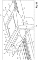
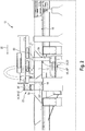
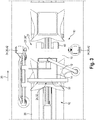
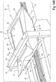
- the Figure 1A , 1B , 2 and 3 show an embodiment of a stretching device 10.
- the stretching device 10 is designed to stretch a package 12.
- An object 14 is packed in the package 12.
- the package 12 has a packaging section 16 which is arranged on the side of the package 12 and from the package 12 protrudes.
- the stretching device 10 has a transport device 18, a holding device 22 and a movement device 24.
- the transport device 18 is designed to transport the object 14 in a transport direction 20.
- the packaging 12 has an upstream end face 28 'and a downstream end face 28 "with respect to the transport direction 20. Furthermore, the packaging 12 has four longitudinal sides 30', 30", 30 '"and 30" “with respect to the transport direction 20.
- the longitudinal side 30 'facing the transport device (18) faces the transport device 18 and is at least partially in contact with the transport device 18.
- the packaging 12 therefore rests on the transport device 18 with the longitudinal side 30' facing the transport device (18) (18) Long side 30 ′ ′′ facing away from the transport device 18 faces away.
- Two lateral longitudinal sides 30 ′′ and 30 ′′ ′′ are arranged to the side of the transport device 18 and are essentially perpendicular to the transport device 18.
- the protruding packaging section 16 is arranged on the downstream end face 28 ′′ of the packaging 12.
- the transport device 18 has a transport plane 38 on which the object 14 and the packaging 12 are transported.
- the transport device 18 also has recesses 40 on the two edges of the transport plane 38, so that the packaging 12 and the object 14 only rest in a central area on the transport device 18 and the transport plane 38.
- the holding device 22 has two rollers 26 ', 26 "arranged perpendicular to the transport direction 18.
- the two rollers 26', 26" are arranged parallel to one another.
- the holding device 22 furthermore has a roller rotation drive device 34 for rotating the rollers 26', 26" and a roller translation drive device 36 for moving the rollers 26 ',
- the holding device 22 furthermore has a roller carrier device 42 in which the rollers 26 ', 26 "are arranged to be rotatable and movable relative to one another.
- the roller carrier device 42 forms the roller rotation drive device 34 and the roller translation drive device 26.
- the roller rotation drive means 34 may preferably have the rollers 26 ', 26 "in opposite directions Drive direction.
- the protruding packaging section can be drawn in between the rollers.
- the roller translation drive device 36 is designed to move the rollers relative to one another. In this exemplary embodiment, this relative movement takes place particularly perpendicular to the transport plane 38. It can be particularly advantageous if the distance between the rollers when inserting the protruding packaging section is large and the rollers are moved towards each other after the insertion of the packaging section in order to clamp the protruding packaging section between them.
- the invention is not limited to two In an alternative embodiment, three, four, five or more rollers can also be arranged in order to hold the protruding packaging section between them.
- the movement device 24 is designed to move the object 14 with the packaging 12.
- the movement device 24 has a vertical drive 44 for vertical movement perpendicular to the transport plane 38 and a horizontal drive 46 for movement parallel to the transport plane 38, in particular parallel to the transport direction 20.
- the movement device 24 furthermore has a clamping device 32, which is designed to clamp the packaging 12 and the object 14 between them.
- the clamping device 32 has lifting elements 48 ′, 48 ′′ and a stop element 50.
- the lifting elements 48 ′, 48 ′′ are arranged in such a way that they are moved through the two recesses 40 of the transport plane 38 during a vertical movement perpendicular to the transport plane 38.
- the lifting elements 48 ', 48 "have a bearing surface 52 which come into contact with the longitudinal side 30' of the packaging 12 facing the transport device (18).
- the bearing surface 52 comes in particular in an upstream region of the longitudinal side facing the transport device (18) 30 'in contact with the longitudinal side 30' facing the transport device (18).
- the vertical drive 44 is designed to move the lifting elements 48 ', 48 "perpendicular to the transport plane 38.
- the object 14 with the packaging 12 can thus be moved perpendicular to the transport plane 38.
- the stop element 50 has a contact surface 54 against which the packaging 12 comes into contact with the longitudinal side 30 '"facing away from the transport device (18) when it is clamped.
- the contact surface 54 comes into contact in particular in an upstream area of that facing away from the transport device (18) Long side 30 '' attached the longitudinal side 30 ′′ ′ facing away from the transport device (18).
- the movement device 24 also has a frame 56, which contains the stop element 50 and connects the stop element 50 to the remaining components of the movement device 24, which are largely arranged on the side of the transport device (18) facing away from the packaging.
- the frame 56 has a height 57 ′ which is greater than a height 13 ′ of the packaging 12.
- the frame 56 also has a width 57 ′′, which is greater than a width 13 ′′ of the packaging 12 and greater than a width 19 of the transport device 18. This can prevent the packaging 12 from coming into lateral contact with the frame 56 during transport, in particular from dragging it or gets stuck.
- the horizontal drive 46 of the movement device 24 is designed to move the packaging 12 and the object 14 parallel to the transport plane 38, in particular parallel to the transport direction 20.
- the horizontal drive 46 moves both the lifting elements 48 ', 48 "and the frame 56 with the stop element 50 in the horizontal direction. This enables the packaging to be clamped simultaneously by the clamping device 32 while it is parallel to the transport plane 38, is moved in particular parallel to the transport direction 20.
- the movement device 24 can be designed to move the object 14 and the packaging 12 towards the rollers 26 ', 26 "in order to guide the protruding packaging section 16 between the two rollers 26', 26". Between the two rollers 26 ', 26 "there is a central plane 58 which is parallel to the transport plane and which is at the same distance from the rollers 26', 26".
- the protruding packaging section 16 is arranged during clamping in the clamping device 32 of the movement device 24 so that it lies in the central plane 58. It is thereby achieved in a simple manner that the protruding packaging section 16 can be guided through the space between the two rollers 26 ', 26 ".
- the rollers 26', 26" can be guided by means of of the roller translation drive device 36 are further spaced from one another in order to produce a larger gap between the rollers 26 ', 26 "through which the protruding packaging section 16 can be guided.
- the rollers 26' , 26 are not only movable relative to one another, but are also movable parallel to one another perpendicular to the transport plane 38. This enables the center plane 58, which lies between the rollers 26 ′, 26 ′′, to be displaced at the level of the protruding packaging section 16.
- a stretching device 10 can be provided that instead of or in addition to the movement device 24, the holding device 22 can be moved parallel to the transport direction 20.
- the holding device 22 can have, for example, a horizontal drive which can move the holding device 22 parallel to the transport direction 20.
- the object 14 and the holding device 22 are moved relatively away from one another and the packaging section 16 can thereby also be stretched.
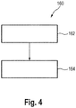
- Fig. 4 shows an embodiment of a method 160 for stretching a package 12, in particular a bag, for an object 14, in particular a pharmaceutical or cosmetic object.
- the stretching device 10, which is in the 1A to 3 is described is particularly suitable for performing the method 160 for stretching.
- the packaging 12 to be stretched here has a protruding packaging section 16.
- the object 14 is transported on a transport device 18 in a transport direction 20. The individual process steps are described in more detail below.
- the protruding packaging section 16 is held by a holding device 22.
- the holding device 22 has two perpendicular to the transport direction 20 arranged rollers 26 ', 26 ".
- the protruding packaging section 16 is held between the two rollers 26', 26".
- the invention is not limited to two roles. In an alternative embodiment, three, four, five or more rollers can also be arranged in order to hold the protruding packaging section between them.
- a second step 164 the object 14 is moved away from the holding device 22 and parallel to the transport device 20. During this movement, the protruding packaging section 16 is stretched because it is held between the rollers 26 ', 26 ".
- the holding device 22 can also be moved parallel to the transport direction 20 and away from the object 14. During this movement, the protruding packaging section 16 is also stretched since it is held between the rollers 26 ', 26 ".
- the packaging 12 is preferably held on at least one longitudinal side 30 ′, 30 ′′, 30 ′′ ′, 30 ′′ ′′ by a moving device 24.
- the movement device 24 can in particular be designed as such a movement device as it is in the stretching device 10 in the 1A to 3 is described.
- the protruding packaging section 16 is preferably arranged on the downstream end face 28 'with respect to the transport direction 20. In this case, in the second step of moving 164, the object 14 is moved opposite to the transport direction 20 and away from the holding device 22.
- the rollers 26 ', 26 are preferably rotated in the opposite direction, as a result of which the protruding packaging incision 16 is drawn in between the rollers 26', 26".
- the rollers 26 ', 26 are preferably moved relative to one another, as a result of which the rollers 26', 26" clamp the protruding packaging section 16 between them.
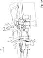
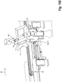
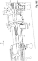
- FIGS. 5a to 5d show an isometric representation of the individual method steps of the method 160 for stretching a package 12, which is shown in FIG Fig. 4 is described.
- Figure 5a shows a first sub-step of step 162 of holding, wherein a downstream area of the protruding packaging section 16 is arranged between the rollers 26 ', 26 ".
- the downstream area of the packaging section 16 is thereby preferably arranged between the rollers 26', 26", that the movement device 24 moves the packaging 12 parallel to the transport direction 20 towards the rollers and introduces the protruding packaging section 16 between the rollers 26 ', 26 ".
- Figure 5b shows a second substep of step 162 of holding, in which the protruding packaging section 16 is drawn in between the rollers 26 ', 26 ".
- the rollers 26', 26" are thereby moved relative to one another until they come into contact with the protruding packaging section 16 are.
- Figure 5c shows an isometric representation of a third sub-step of step 162 of holding, in which the protruding packaging section 16 is held between the rollers 26 ', 26 ".
- the rollers 26', 26" can be pressed against one another to prevent the protruding Clamp packaging section 16 between them.
- the rollers 26 ', 26 ′′ can be designed to rotate continuously in opposite directions in order to exert a uniform and constant tensile force on the protruding packaging section 16. This tensile force also allows the protruding packaging section 16 to be positioned between the rollers 26', 26 "are held.
- the packaging section 16 can in particular be made uniform and opposite Rotation of the rollers 26 ', 26 "towards one another and a pressing of the rollers 26', 26" on one another are held between the rollers 26 ', 26 ".
- FIG. 5d Figure 4 shows an isometric view of the moving step 164 in which the package 12 and object 14 is moved away from the rollers 26 ', 26 "by the mover 24, whereby the protruding package section 16 and a portion of the downstream face 28" of the package 12 can be stretched.
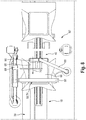
- the Figure 6A , 6B , 7th and 8th show an embodiment of a deployment device 60 '.
- the unfolding device 60 ′ is designed to unfold a folded-in packaging section 16 of a packaging 12.
- An object 14 is packed in the package 12.
- the unfolding device 60 ′ has a transport device 18, a lifting device 62, a holding device 64 and a holding device drive device 68.
- the transport device 18 is designed to transport the object 14 in a transport direction 20.
- the packaging 12 has an upstream end face 28 'and a downstream end face 28 "with respect to the transport direction 20. Furthermore, the packaging 12 has four longitudinal sides 30', 30", 30 '"and 30""with respect to the transport direction 20
- the longitudinal side 30 'facing the transport device (18) faces the transport device and is at least partially in contact with the transport device 18.
- the packaging 12 therefore rests on the transport device 18 with the longitudinal side 30' facing the transport device (18).
- Two lateral longitudinal sides 30 ′′ and 30 ′′ ′′ are arranged to the side of the transport device 18 and are essentially perpendicular to the transport device 18.
- the packaging section 16 is connected to the rest of the packaging on the downstream end 28 ′′ of the packaging 12.
- the packaging section 16 initially extends along the downstream end face 28 "in the direction of the longitudinal side 30 'of the packaging 12 facing the transport device (18) and further partially along the longitudinal side 30' of the packaging 12 facing the transport device (18).
- the packaging section 16 is thus partially arranged between the longitudinal side 30 'of the packaging 12 facing the transport device (18) and the transport device 18.
- the packaging section 16 is thus initially between the transport device 18 and that of the transport device (18) facing longitudinal side 30 'of the packaging 12 folded in.
- the transport device 18 has a transport plane 38 on which the object 14 and the packaging 12 are transported.
- the transport device 38 also has recesses 40 on the two edges of the transport plane 38, so that the packaging 12 and the object 14 only rest in a central area on the transport device 18 and the transport plane 38.
- the lifting device 62 is designed to lift the object 14 with the packaging 12.
- the lifting device 62 has a vertical drive 76 for vertically moving the object perpendicular to the transport plane 38.
- the lifting device 62 furthermore has a clamping device 74 which is designed to clamp the packaging 12 and the object 14 between them.
- the clamping device 74 has lifting elements 78 ', 78 "and a stop element 80.
- the lifting elements 78', 78" are arranged in such a way that they are moved through the two recesses 40 of the transport plane 38 during a vertical movement perpendicular to the transport plane 78.
- the lifting elements 78 ', 78 “have a support surface 82 which come into contact with the longitudinal side 30' of the packaging 12 facing the transport device (18).
- the support surface 82 comes in particular in an upstream region of the longitudinal side facing the transport device (18) 30 'in contact with the longitudinal side 30' facing the transport device (18).
- the vertical drive 76 is designed to move the lifting elements 78 ', 78 "perpendicular to the transport plane 38.
- the object 14 with the packaging 12 can thus be moved perpendicular to the transport plane 38.
- the stop element 80 has a contact surface 84 against which the packaging 12 comes into contact with the longitudinal side 30 '"facing away from the transport device (18) when it is clamped.
- the contact surface 84 comes into contact in particular in an upstream area of that facing away from the transport device (18) Longitudinal side 30 '"in contact with the longitudinal side 30"' facing away from the transport device (18).
- the lifting device 62 furthermore has a frame 86 which contains the stop element 80 and the stop element 80 with the remaining components of the lifting device 62 connects, which are largely arranged on the side of the transport device 18 facing away from the packaging (12).
- the frame 86 has a height 87 ′ which is greater than a height 13 ′ of the packaging 12.
- the frame 86 also has a width 87 ′′, which is greater than a width 13 ′′ of the packaging 12 and greater than a width 19 of the transport device 18. This can prevent the packaging 12 from coming into lateral contact with the frame 86 during transport, in particular from dragging it or gets stuck.
- the holding device 64 has a suction device 72 which sucks and holds a region 66 of the packaging 12 adjacent to the packaging section 16.
- the adjacent area 66 corresponds to a downstream area of the longitudinal side 30 '' 'facing away from the transport device (18).
- the suction device 72 also has a suction head 90, a hose 88 and a device (not shown) for generating a negative pressure 90 is in contact with the adjacent area 66 in order to suck it in.
- the hose 88 connects the suction head 90 to the device for generating a negative pressure, not shown.
- the device for generating a negative pressure can be, for example, a vacuum pump.
- the holding device drive device 68 is designed to move the suction device 72 parallel to the transport direction 20.
- the holding device drive device 68 can move the suction device in the opposite direction to the transport direction when the suction device 72 sucks in and holds the adjacent area 66 of the packaging 12. As a result, the folded-in packaging section 16 is unfolded.
- the holding device drive device 68 can furthermore be designed to move the suction device 72 by means of a pivoting movement or a lifting movement.
- a folding device 60 ' can be provided that the initially folded packaging section 16 is folded onto the longitudinal side 30'"of the packaging 12 facing away from the transport device 18 instead of the side of the packaging 12 facing the transport device 18. Accordingly, the holding device 62 is also open the longitudinal side 30 'of the packaging 12 facing the transport device 18 and engages the longitudinal side 30' of the packaging 12 facing the transport device 18, the longitudinal side 30 'facing the transport device 18 being an adjacent area 66 of the packaging section 16. Mlt of such an arrangement the folded packaging section can also be unfolded.
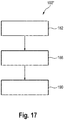
- Fig. 9 shows an embodiment of a method 180 ′ for unfolding a packaging part 16 of a packaging 12, in particular a bag, for an object 14, in particular a pharmaceutical or cosmetic object.
- the deployment device 60 'shown in Figures 6A through 8 is described is particularly suitable for carrying out the method 180 'for unfolding.
- the object 14 is transported on a transport device 18 in a transport direction 20.
- the packaging section 16 is initially folded in between the transport device 18 and the packaging 12, in particular a longitudinal side 30 ′ of the packaging 12 facing the transport device (18).
- the individual process steps are described in more detail below.
- a first step 182 the object 14 is lifted by the transport device 18 by a lifting device 62.
- the lifting device 62 can have a stop element 80 on the side of the packaging facing away from the transport device (18), against which the packaging 12 and the object 14 are pressed when the object 14 is lifted 182.
- the lifting device 62 is thereby designed in particular to lift and hold the packaging 12 and the object 14.
- the lifting device 62 preferably holds the packaging 12 on at least one side surface 30 ', 30 ", 30"', 30 "".
- the lifting device 62 can also lift the transport device 18, in particular the transport plane 38 of the transport device 18, at least in the support area of the packaging 12 on the transport plane 38.
- an area 66 of the packaging 12 adjacent to the packaging section 16 is held by a holding device 64.
- the adjacent area 66 corresponds in particular to a downstream area of the longitudinal side 30 "'facing away from the transport device (18).
- the holding device 64 can preferably have a suction device 72 which sucks and holds the adjacent area 66.
- the holding device 64 preferably holds the packaging 12 on the longitudinal side 30 '' 'facing away from the transport device (18).
- a third step 186 the holding device 64 is moved in a direction 70 pointing away from the packaging section 16. During this movement, a tensile force is exerted on the folded-in packaging section 16, which pulls the folded-in packaging section 16 out of its folded-in position between the transport device 18 and the packaging 12 and thus folds it out.
- the holding device 64 is preferably moved parallel to the transport direction 20, whereby the packaging section 16 is folded out.
- FIGS. 10a to 10c show an isometric representation of the individual method steps of the method 180 'for unfolding the packaging section 16, which is shown in FIG Fig. 9 is described.
- Figure 10a shows the lifting step 182, in which the lifting device 62 is arranged on the side of the object 14 facing the transport device (18) and is designed to lift the object 14 and the packaging 12 through a movement perpendicular to the transport plane 38.
- the The longitudinal side 30 '"facing away from the transport device (18) is pressed against a stop element 80.
- the stop element 80 comes into contact with an upstream region of the longitudinal side 30'" facing away from the transport device (18). Because the lifting device 64 presses the object 14 and the packaging 12 against the stop element 80, the object 14 and the packaging 12 are thereby clamped and held.
- Figure 10b shows an isometric representation of the step of holding 184, in which a suction device 72 sucks a downstream region of the longitudinal side 30 '"facing away from the transport device (18).
- the folded-in packaging section is connected to the packaging 12 on the downstream end face 28".
- the downstream area of the longitudinal side 30 ′ ′′ facing away from the transport device (18) thus corresponds to an area 66 adjacent to the packaging section 16.
- Figure 10c shows an isometric representation of the step of moving 186, in which the holding device is moved by means of a holding device drive device opposite to the transport direction 20 and away from the packaging section 16.
- the suction device 72 is particularly moved towards the stop element 80 of the lifting device 62.
- the folded-in packaging section 16 is pulled out of a folded-in position between the transport device 18 and the longitudinal side 30 ′ facing the transport device (18) and is unfolded.
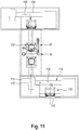
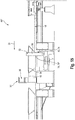
- Fig. 11 shows an embodiment of an unpacking system 100.
- the unpacking system 100 has a transport device 18, a folding device 60, a stretching device 10, and a separating device 108.
- the unfolding device 60 can here either by the Figure 6A , 6B , 7th , 8th described embodiment of a folding device 60 'or by the in the Figure 14A , 14B , 15th , 16 described embodiment of a folding device 60 ′′ be formed.
- the transport device 18 has a transport plane 38 on which an object 14, in particular a pharmaceutical or cosmetic object, is transported.
- the object is packed in a package, in particular a bag.
- the packaging 12 has a packaging section 16 which is initially folded in between the transport device 18 and the packaging 12.
- the object 14 is transported on the transport device 18 in a transport direction 20.
- the transport device 18 is designed to transport the wrapped object 14 to the unfolding device 60, from the stretching device 10 to the severing device 108, and away from the severing device 108.
- the folding device 60 and the stretching device 10 are arranged directly next to one another.
- the unpacking system 100 can in particular have one or more first movable carrier holders 102 which form the lifting device 64 of the unfolding device 60 and the movement device 24 of the stretching device 10.
- the unpacking system 100 can furthermore in particular have one or more second movable carrier holders 103 which form the stop device 92 of the unfolding device 60 ′′ and the holding device 22 of the stretching device 10.
- the first and second carrier holders 102, 103 can in particular be perpendicular and / or parallel to the Transport direction be movable.
- the stretching device 10 and the unfolding device 60 are arranged at a distance from one another and the transport device 18 is designed to transport the object 14 from the unfolding device 60 to the stretching device 10.
- the separating device 108 has a cutting knife, a removal device and a disposal device.
- the cutting knife is arranged in such a way that it can be moved perpendicularly to the transport direction in order to cut off the protruding packaging section 16 and thus to open the packaging 12.
- a laser, a gripping knife or a thermal cutting method such as a hot wire or hot air, can be used to separate the protruding packaging section 16 from the packaging 12.
- the removal device is designed to remove the object 14 from the packaging 12, that is to say that the removal device is designed to separate the object 14 and the packaging 12 from one another.
- a holding device can hold the packaging for this purpose and a gripping device can remove the object from the packaging.
- the object can be held with a holding device, while a gripping device holds the package and pulls it down from the object 14.
- the disposal device is designed to dispose of the separated packaging section 16 and the rest of the packaging 12.
- the two separate packaging parts of the packaging 12 can be disposed of separately from one another or together.
- the disposal device can, for example, have a further transport device, for example a conveyor belt, on which the packaging residues are placed and by which the packaging residues are transported away from the separating device 108.
- the transport device can be designed to transport the unpacked object 14 from the separating device 108 into a clean room 124.
- the transport device 18 is not constructed linearly but between the individual devices, the folding device 60, the stretching device 10 and / or the Separating device 108 as well as upstream of the unfolding device 60 and downstream of the separating device 108, has deflection sections which cause a change in the direction of the transport direction 20.
- the transport device 18 can have a first deflection section 104, in particular upstream of the unfolding device 60, which brings about a first change in direction 106 of the transport direction 20, in particular wherein the first change in direction 106 is 90 °.
- the transport device 18 can have a second deflecting section 110 between the stretching device 10 and the severing device 108, which changes a second direction 112 of the transport direction 20, in particular the second change in direction 112 being 90 °.
- the transport device 18 can have a third deflection section 114 upstream of, in or downstream of the separating device 108, which brings about a third change in direction 116 of the transport direction 20, in particular the third change in direction 116 being 90 °.
- the unpacking system has an unfolding device 60 ′′, as in FIGS Figures 14A to 18C described, a stretching device 10, as in Figures 1A to 5D and a separation device 108 which is identical to the separation device 108 of the in Fig. 11 described unpacking system 100 has.
- the unfolding device 60 ′′ does not have a lifting device and the stretching device 10 has no movement device. Instead, the packaging is transported continuously on the transport device 18 downstream in the transport direction 20.
- the unpacking system has a carrier holder 103 which forms the stop device 92 of the opening device 60 "and the holding device 24 of the stretching device 10.
- the roller 94 'of the stop device 92 corresponds to the roll 26" of the holding device 24 and the roller 94 "of the stop device 92 of the roll 26 ′′ of the holding device 24.
- Such an arrangement of an unpacking system requires that the packaging section 16 is arranged on the upstream face of the packaging 12 and extends from there to one of the longitudinal sides that either face or face away from the transport device. Furthermore, the rollers 26 ', 26 "and 94', 94" are designed to be movable relative to one another, on the one hand to space the rollers so far from one another that the packaging 12 can be transported through between the rollers and that one of the rollers has a stop for the folded Can form packaging portion, and on the other hand to clamp the packaging portion 16 between them and hold.
- the object 14 is transported on the transport device 18 downstream in the transport direction 20.
- the rollers 26 ', 26 “or 94', 94" are spaced apart from one another to such an extent that the packaging 12 can be guided through between the rollers 26 ', 26 "or 94', 94".
- the rollers 26 ', 26 “or 94', 94" are brought into contact with the longitudinal side 30 ', 30 "facing and facing away from the transport device 18.
- One of the rollers thereby forms a stop for the folded-in packaging section 16.
- the transport device 18 is transported the object 12 further, whereby the packaging section 16 is pressed against one of the rollers which forms the stop. This unfolds the packaging section 16.
- the rollers are then moved relative to one another in order to clamp and hold the packaging section 16, whereby the packaging section 16 is stretched.
- the alternative unpacking system preferably has a clamping device which is designed to be movable both parallel and perpendicular to the transport direction.
- the clamping device is arranged downstream of the carrier holder 103, which forms the stop device 92 and the holding device 24.
- the clamping device clamps the package 12 and the object 14 between itself after it has partially passed the rollers. So that the object 14 and the packaging 12 are only stopped briefly or not at all, the clamping device moves downstream in the transport direction 20 with the object after clamping at a speed that corresponds to the conveying speed of the transport device 18. This improves the unfolding and stretching.
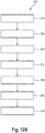
- Figure 12A shows a first embodiment of a method 200 ′ for unpacking an object 14, in particular a pharmaceutical or cosmetic object, from a packaging 12, in particular a bag.
- the object 14 is on a transport device 18 transported in a transport direction 20.
- a packaging section 16 of the packaging 12 is initially folded in between the transport device 18 and the packaging 12.
- a step 202 the packaging section 16 is made by means of the method 180 described in FIGS Fig. 9 and 10a to 10c is described, unfolded.
- the method 180 can either be performed by the Fig. 9 described embodiment of a method for unfolding 180 'or by the in Fig. 17 described embodiment of a method for unfolding 180 ′′ are carried out.
- the protruding packaging section 16 is removed by means of the method 160, which is described in the Fig. 4 and 5a to 5d is described, stretched.
- the object 14 is removed from the opened packaging 12.
- the individual steps 202 to 208 of the method 200 ′ for unpacking are preferably carried out one after the other.
- FIG. 2 shows a second embodiment of a method 200 ′′ for unpacking an object 14, in particular a pharmaceutical or cosmetic object, from a packaging 12, in particular a bag.
- the object 14 is transported on a transport device 18 in a transport direction 20.
- a packaging section 16 of the packaging 12 is initially folded in between the transport device 18 and the packaging 12. The individual method steps are described in more detail below.
- a step 210 the object 14 is transported on the transport device 18.
- the object 14 is preferably deflected in a first deflecting section 104 in the step 210 of being transported, with the transport direction 20 being changed, in particular with this change in direction being 90 °.
- the packaging section 16 is made using the method 180, which is described in the Fig. 9 and 10a to 10c is described, unfolded.
- the method 180 can either be performed by the Fig. 9 described embodiment of a method for unfolding 180 'or by the in Fig. 17 described embodiment of a method for unfolding 180 ′′ are carried out.
- the protruding packaging section 16 is removed by means of the method 160, which is described in the Fig. 4 and 5a to 5d is described, stretched.
- the object 14 is transported further on the transport device 18.
- the object 14 is preferably deflected in a second deflection section 110, the transport direction 20 being changed, in particular this change in direction being 90 °.
- the object 14 is removed from the opened packaging 12.
- the object 14 is transported away on the transport device 18.
- the object 14 is preferably in the step 214 of transporting away or in the step 212 of further transporting in a third deflection section 114 of the transport device 18 deflected, with the transport direction 20 being changed, in particular with this change in direction being 90 °.
- the object 14 is preferably transported into a clean room 124 in step 214 of removal.
- the individual steps 210, 202, 204, 212, 206, 208 and 214 of the method 200 ′′ for unpacking are preferably carried out one after the other.
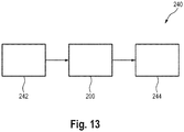
- Fig. 13 shows a schematic representation of a filling system 140.
- filling systems are designed to unpack an object that stores liquid, to fill or transfer the liquid into containers and then to pack the containers.
- the filling systems usually have an unpacking device, a filling device and a packing device.
- the filling system 140 described has upstream modules 142, an unpacking system 100 and downstream modules 144.
- the unpacking system 100 can correspond to the in Fig. 11 unpacking system 100 described correspond.
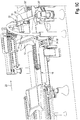
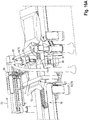
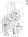
- the Figure 14A , 14B , 15th and 16 show an embodiment of a fold-out device 60 ′′.
- the fold-out device 60 ′′ is designed to fold out a folded-in packaging section 16 of a packaging 12.
- An object 14 is packed in the package 12.
- the unfolding device 60 ′′ has a transport device 18, a lifting device 62 and a stop device 92.
- the transport device 18 is designed to transport the object 14 in a transport direction 20.
- the packaging 12 has an upstream end face 28 'and a downstream end face 28 "with respect to the transport direction 20. Furthermore, the packaging 12 has four longitudinal sides 30', 30", 30 '"and 30""with respect to the transport direction 20
- the long side 30 'facing the transport device 18 faces the transport device and is at least partially in contact with the transport device 18.
- the packaging 12 therefore rests on the transport device 18 with the long side 30' facing the transport device 18.
- An upper longitudinal side 30 '" is from facing away from the transport device 18.
- Two lateral long sides 30 "and 30 ′′ ′′ are arranged to the side of the transport device 18 and are essentially perpendicular to the transport device 18.
- the packaging section 16 is connected to the rest of the packaging 12 at the downstream end face 28 ′′ of the package 12.
- the packaging section 16 initially extends along the downstream end face 28 ′′ in the direction of the longitudinal side 30 ′ of the package 12 facing the transport device 18 and further along in part the longitudinal side 30 ′ of the packaging 12 facing the transport device 18.
- the packaging section 16 is thus partially arranged between the longitudinal side 30 ′ of the packaging 12 facing the transport device 18 and the transport device 18.
- the packaging section 16 is thus initially folded in between the transport device 18 and the longitudinal side 30 ′ of the packaging 12 facing the transport device 18.
- the packaging section 16 can initially extend along the downstream end face 28 "in the direction of the longitudinal side 30 '" of the packaging 12 facing away from the transport device 18 and further partially along the longitudinal side 30' "of the packaging 12 facing away from the transport device 18. The packaging section 16 is thus Folded into the longitudinal side 30 ′ ′′ of the packaging 12 facing away from the transport device 18.
- the transport device 18 has a transport plane 38 on which the object 14 and the packaging 12 are transported.
- the transport device 18 also has recesses 40 on the two edges of the transport plane 38, so that the packaging 12 and the object 14 only rest in a central area on the transport device 18 and the transport plane 38.
- the lifting device 62 is designed to lift the object 14 with the packaging 12.
- the lifting device 62 has a vertical drive 76 for vertically moving the object perpendicular to the transport plane 38.
- the lifting device 62 furthermore has a clamping device 74 which is designed to clamp the packaging 12 and the object 14 between them.
- the clamping device 74 has lifting elements 78 ', 78 "and a stop element 80.
- the lifting elements 78', 78" are arranged in such a way that they are moved through the two recesses 40 of the transport plane 38 during a vertical movement perpendicular to the transport plane 78.
- the lifting elements 78 ', 78 “have a bearing surface 82 which come into contact with the longitudinal side 30' of the packaging 12 facing the transport device 18.
- the bearing surface 82 comes into contact in particular in an upstream region of the longitudinal side 30 'facing the transport device 18 to the longitudinal side 30 ′ facing the transport device 18.
- the vertical drive 76 is designed to move the lifting elements 78 ′, 78 ′′ perpendicular to the transport plane 38.
- the object 14 with the packaging 12 can thus be moved perpendicular to the transport plane 38.
- the stop element 80 has a contact surface 84 on which the packaging 12 comes into contact with the longitudinal side 30 '"facing away from the transport device 18 when it is clamped.
- the contact surface 84 comes in particular in an upstream region of the longitudinal side 30'" facing away from the transport device 18. in contact with the longitudinal side 30 ′′ ′ facing away from the transport device 18.
- the lifting device 62 furthermore has a frame 86 which contains the stop element 80 and connects the stop element 80 to the remaining components of the lifting device 62, which are largely arranged on the side of the transport device 18 facing away from the packaging 12.
- the frame 86 has a height 87 ′ which is greater than a height 13 ′ of the packaging 12.
- the frame 86 also has a width 87 ′′, which is greater than a width 13 ′′ of the packaging 12 and greater than a width 19 of the transport device 18. This can prevent the packaging 12 from coming into lateral contact with the frame 86 during transport, in particular from dragging it or gets stuck.
- the stop device 92 is designed to form a stop for the packaging section 16.
- the stop device 92 has two rollers 94 ', 94 "for this purpose, a first roller 94' of the rollers 94 ', 94" on the longitudinal side 30' of the packaging 12 facing the transport device 18 and a second roller 94 "of the rollers 94 ', 94 "is arranged on the longitudinal side 30 '" of the packaging 12 facing away from the transport device 18.
- the stop device 92 furthermore has a roller translation drive device 96 which can move the rollers 94 ′, 94 ′′ relative to one another and perpendicular to the transport direction 20.
- the stop device 92 can have only one roller 94.
- the roller 94 is arranged on the longitudinal side 30 ', 30' "on which the packaging section 16 is folded.
- Fig. 17 shows a further embodiment of a method 180 ′′ for unfolding a packaging part 16 of a packaging 12, in particular a bag, for an object 14, in particular a pharmaceutical or cosmetic object.
- the unfolding device 60 ′ which is shown in FIG Figures 14A through 16 is particularly suitable for carrying out the method 180 ′′ for unfolding.
- the object 14 is transported on a transport device 18 in a transport direction 20.
- the packaging section 16 can initially be folded in between the transport device 18 and the packaging 12, in particular a longitudinal side 30 ′ of the packaging 12 facing the transport device 18. Alternatively, the packaging section 16 can initially also be folded onto the longitudinal side 30 ′ ′′ of the packaging 12 facing away from the transport device 18. The individual method steps are described in more detail below.
- a first step 182 the object 14 is lifted by the transport device 18 by a lifting device 62.
- the lifting device 62 can have a stop element 80 on the side of the packaging facing away from the transport device 18, against which the package 12 and the object 14 are pressed when the object 14 is lifted 182.
- the lifting device 62 is thereby designed in particular to lift and hold the packaging 12 and the object 14.
- the lifting device 62 preferably holds the packaging 12 on at least one side surface 30 ', 30 ", 30"', 30 "".
- the lifting device 62 can also lift the transport device 18, in particular the transport plane 38 of the transport device 18, at least in the support area of the packaging 12 on the transport plane 38.
- a second step 188 the lifting device 62 and the stop device 92 are moved parallel to the transport direction 20 relative to one another in such a way that the packaging 12 is arranged at least in sections on the stop device 92, with a roller 94 of the stop device 92 on a longitudinal side 30 ', 30 '"of the packaging 12 is arranged in order to form a stop for the packaging section 16.
- the roller 94 is preferably arranged such that the packaging 12 can at least partially pass the roller 94.
- the roller 94 is arranged before the step of moving 188 such that the roller 94 rests against the longitudinal side of the packaging 12 after the relative movement 188, on which the packaging section 16 is folded in and forms a stop for the folded packaging section 16.
- the roller can also be arranged such that, after the relative movement 188, the roller 94 is arranged on the side of the packaging 12 on which the packaging section 16 is folded in and is not in contact with the packaging 12.
- the stop device 92 can have a drive device which moves the roller 94 perpendicular to the transport direction 20 and the roller 94 in contact with the packaging conveyed and then forms a stop for the folded packaging section 16.
- the stop device 92 can have two rollers 94 ', 94 ", with a first roller 94' of the rollers 94 ', 94" on the longitudinal side 30' of the packaging 12 facing the transport device 18 and a second roller 94 "of the rollers 94 ', 94 "is arranged on the longitudinal side 30'" of the packaging 12 facing away from the transport device 18.
- rollers 94 ', 94 are arranged before the step of moving 188 such that the distance between the rollers 94', 94" is so great that the packaging 12 can be relatively moved through the rollers 94 ', 94 "
- the roller of rollers 94 ′, 94 ′′ which is arranged on the longitudinal side onto which the packaging section 16 is folded is arranged in such a way that it forms a stop for the packaging section 16
- a third step 190 the lifting device 62 and the stop device 92 are moved relative to one another parallel to the transport direction 20 such that the folded-in packaging section 16 is unfolded.
- the folded-in packaging part 16 is pushed by means of the roller along the longitudinal side on which the packaging section is arranged and thereby folded out.
- FIGS. 18A to 18C show an isometric illustration of the individual method steps of the method 180 ′′ for unfolding the packaging section 16, which is shown in FIG Fig. 17 is described.
- Figure 18A shows the lifting step 182, in which the lifting device 62 is arranged on the side of the object 14 facing the transport device 18 and is designed to lift the object 14 and the packaging 12 by a movement perpendicular to the transport plane 38.
- the longitudinal side 30 ′ ′′ facing away from the transport device 18 is pressed against a stop element 80.
- the stop element 80 comes with an upstream region of the the longitudinal side 30 '′′ facing away from the transport device 18 in contact. Because the lifting device 64 presses the object 14 and the packaging 12 against the stop element 80, the object 14 and the packaging 12 are clamped and held thereby.
- Figure 18B 13 shows an isometric illustration of the step of the first relative movement 188 in which the object 14 and the package 12 are moved between the rollers 94 ', 94 "until the rollers 94', 94" are located upstream of the packaging section 16.
- the object is moved downstream in the transport direction 20 by means of the lifting device.
- the rollers 94 ', 94 “are spaced apart from one another to such an extent that the packaging 12 can be guided through between the rollers 94', 94".
- rollers 94 ', 94 are in contact with the packaging 12 downstream of the packaging section 16, the first roller 94' on the longitudinal side 30 'facing the transport device and the second roller 94" on the The longitudinal side 30 ′ ′′ facing away from the transport device rest.
- the roller 94 ′ forms a stop for the packaging section 16.
- Figure 18C shows an isometric representation of the step of the second relative movement 190, in which the object 14 and the packaging 12 are moved parallel to the transport direction 20 such that the packaging section 16 is moved against the roller 94 ′′, comes into contact with the roller 94 ′′ and is unfolded by moving the object 14 and the packaging 12 in this direction.
- the object is, in the example, the Figure 18C , moved upstream opposite to the transport direction 20 by means of the lifting device.
- the rollers 94 ′, 94 ′′ can optionally be moved relative to one another in such a way that they clamp the unfolded packaging section.
- analogously to the embodiments of the stretching device 10 and the method 160 for stretching from the Figures 1A to 5D be stretched.
- the stop device 92 of the opening device 60 is identical to the holding device 24 of the stretching device 10 and the rollers 94 ', 94" are identical to the rollers 26 ", 26'.
Landscapes
- Engineering & Computer Science (AREA)
- Mechanical Engineering (AREA)
- Control And Other Processes For Unpacking Of Materials (AREA)
- Auxiliary Devices For And Details Of Packaging Control (AREA)
- Supplying Of Containers To The Packaging Station (AREA)
Applications Claiming Priority (3)
| Application Number | Priority Date | Filing Date | Title |
|---|---|---|---|
| DE102017123298 | 2017-10-06 | ||
| DE102017123387.3A DE102017123387B4 (de) | 2017-10-06 | 2017-10-09 | Entpackungssystem für ein in einer Verpackung, Füllanlage mit Entpackungssystem und Verfahren zum Entpacken eines Objektes |
| EP18198880.9A EP3489157B1 (fr) | 2017-10-06 | 2018-10-05 | Système de déballage amélioré pour un objet emballé dans un emballage, en particulier dans un sachet, en particulier un article pharmaceutique ou cosmétique |
Related Parent Applications (2)
| Application Number | Title | Priority Date | Filing Date |
|---|---|---|---|
| EP18198880.9A Division-Into EP3489157B1 (fr) | 2017-10-06 | 2018-10-05 | Système de déballage amélioré pour un objet emballé dans un emballage, en particulier dans un sachet, en particulier un article pharmaceutique ou cosmétique |
| EP18198880.9A Division EP3489157B1 (fr) | 2017-10-06 | 2018-10-05 | Système de déballage amélioré pour un objet emballé dans un emballage, en particulier dans un sachet, en particulier un article pharmaceutique ou cosmétique |
Publications (3)
| Publication Number | Publication Date |
|---|---|
| EP3736219A1 true EP3736219A1 (fr) | 2020-11-11 |
| EP3736219B1 EP3736219B1 (fr) | 2023-12-06 |
| EP3736219C0 EP3736219C0 (fr) | 2023-12-06 |
Family
ID=65816788
Family Applications (3)
| Application Number | Title | Priority Date | Filing Date |
|---|---|---|---|
| EP20177476.7A Active EP3736219B1 (fr) | 2017-10-06 | 2018-10-05 | Dispositif de dépliage, méthode et système correspondante |
| EP18198880.9A Active EP3489157B1 (fr) | 2017-10-06 | 2018-10-05 | Système de déballage amélioré pour un objet emballé dans un emballage, en particulier dans un sachet, en particulier un article pharmaceutique ou cosmétique |
| EP26151371.7A Pending EP4707188A3 (fr) | 2017-10-06 | 2018-10-05 | Système de déballage amélioré pour un objet emballé dans un emballage, en particulier un sachet, en particulier un objet pharmaceutique ou cosmétique |
Family Applications After (2)
| Application Number | Title | Priority Date | Filing Date |
|---|---|---|---|
| EP18198880.9A Active EP3489157B1 (fr) | 2017-10-06 | 2018-10-05 | Système de déballage amélioré pour un objet emballé dans un emballage, en particulier dans un sachet, en particulier un article pharmaceutique ou cosmétique |
| EP26151371.7A Pending EP4707188A3 (fr) | 2017-10-06 | 2018-10-05 | Système de déballage amélioré pour un objet emballé dans un emballage, en particulier un sachet, en particulier un objet pharmaceutique ou cosmétique |
Country Status (4)
| Country | Link |
|---|---|
| US (4) | US11111048B2 (fr) |
| EP (3) | EP3736219B1 (fr) |
| DE (2) | DE102017012236B4 (fr) |
| ES (2) | ES2968364T3 (fr) |
Cited By (1)
| Publication number | Priority date | Publication date | Assignee | Title |
|---|---|---|---|---|
| WO2023001763A1 (fr) * | 2021-07-20 | 2023-01-26 | KyooBe Tech GmbH | Système de production et procédé de production d'un produit |
Families Citing this family (14)
| Publication number | Priority date | Publication date | Assignee | Title |
|---|---|---|---|---|
| DE102019206449A1 (de) * | 2019-05-06 | 2020-11-12 | Bausch + Ströbel Maschinenfabrik Ilshofen GmbH + Co. KG | Vorrichtung zum Ausrichten einer Verpackung |
| CN110721986A (zh) * | 2019-11-15 | 2020-01-24 | 楚天科技股份有限公司 | 一种去内膜装置及其去内膜方法 |
| JP7376336B2 (ja) * | 2019-12-11 | 2023-11-08 | 株式会社京都製作所 | 包装体開封システム |
| US11319103B2 (en) * | 2020-03-17 | 2022-05-03 | Gurdeep Singh | Hand-held apparatus for extracting contents of sachet/pouch |
| DE102021104221A1 (de) * | 2021-02-23 | 2022-08-25 | Syntegon Technology Gmbh | Vorrichtung und Verfahren zur Überführung einer Verpackungseinheit in ein Barrieresystem für Pharmazeutika |
| GB2606021B (en) * | 2021-04-23 | 2023-07-19 | Mpac Group Plc | Packaging removal apparatus |
| CN113877974B (zh) * | 2021-10-20 | 2024-09-24 | 华帝股份有限公司 | 一种冲压自动化连线作业工艺布局及方法 |
| CN114348387B (zh) * | 2022-01-24 | 2023-09-12 | 北京味粒子科技有限公司 | 食品自动供应装置 |
| CN115043051B (zh) * | 2022-05-19 | 2023-08-04 | 玉林市第一人民医院 | 新冠病毒核酸检测标本密封袋拆包装置及方法 |
| WO2022195572A2 (fr) * | 2022-05-25 | 2022-09-22 | Indian Institute of Technology Guwahati | Appareil de coupe et de pressage de sachets/poches |
| CN115771656B (zh) * | 2022-11-25 | 2026-04-14 | 上海非夕机器人科技有限公司 | 拭子拆包装置及咽拭子采样机器人 |
| CN115649594B (zh) * | 2022-12-28 | 2023-04-07 | 广汉市迈德乐食品有限公司 | 一种速冻生牛脂快速启封系统及方法 |
| CN121889313A (zh) * | 2023-07-24 | 2026-04-17 | 施耐德两合公司 | 用于将光学工件除去包装的设备和方法以及用途 |
| WO2025203149A1 (fr) | 2024-03-26 | 2025-10-02 | I.M.A. Industria Macchine Automatiche S.P.A. | Procédé et appareil de dépliage automatique d'un rabat d'extrémité de sacs fermés |
Citations (5)
| Publication number | Priority date | Publication date | Assignee | Title |
|---|---|---|---|---|
| WO1997029956A1 (fr) * | 1996-02-14 | 1997-08-21 | Nordisk Plåtindustri Benetec Ab | Systeme d'emballage et de deballage de couvercles de boites de conserve |
| DE102007027878A1 (de) | 2007-06-18 | 2008-12-24 | Robert Bosch Gmbh | Vorrichtung und Verfahren zum Entnehmen eines sterilen Gegenstands aus einer Sterilverpackung |
| DE102009002441A1 (de) * | 2009-04-16 | 2010-10-21 | Robert Bosch Gmbh | Vorrichtung und Verfahren zum Ausrichten von Verpackungen |
| DE202009005086U1 (de) * | 2009-07-30 | 2010-12-16 | Autefa Automation Gmbh | Öffnungseinrichtung |
| DE102014201966A1 (de) * | 2014-02-04 | 2015-08-06 | Robert Bosch Gmbh | Vorrichtung und Verfahren zum Handling eines Trays |
Family Cites Families (15)
| Publication number | Priority date | Publication date | Assignee | Title |
|---|---|---|---|---|
| US5375961A (en) * | 1993-05-07 | 1994-12-27 | Fleetwood Systems, Inc. | Apparatus and method for debagging articles |
| US6725631B2 (en) * | 2001-05-07 | 2004-04-27 | Branko Skrak | Apparatus and method for stripping filmic casings from products |
| DE102006005700A1 (de) * | 2006-02-08 | 2007-08-09 | Robert Bosch Gmbh | Vorrichtung und Verfahren zum Entfernen einer Abdeckfolie von einem Behälter |
| SE532636C2 (sv) * | 2008-07-02 | 2010-03-09 | Ecolean Res & Dev As | Anordning för fyllning av förpackningar |
| IT1401846B1 (it) * | 2010-10-14 | 2013-08-28 | Co Ri M A S R L | Apparato e metodo per rimuovere un prodotto sterile da una confezione sterile che lo contiene |
| DE102010063892B4 (de) | 2010-12-22 | 2023-10-19 | Syntegon Technology Gmbh | Vorrichtung und Verfahren zum Entnehmen eines Objekts aus einer Verpackung |
| ITMI20110814A1 (it) * | 2011-05-11 | 2012-11-12 | Concetti Spa | Apparecchiatura di trasporto e inserimento di mezzi di apertura/chiusura della bocca di sacchi e macchina di riempimento/sigillatura di sacchi dotata di detta apparecchiatura |
| DE102011108798A1 (de) * | 2011-07-29 | 2013-01-31 | Sig Technology Ag | Vorrichtung und Verfahren zum Entpacken und Zuführen von flach gefalteten und aufrecht stehenden Packungsmänteln |
| DE102011080289B4 (de) | 2011-08-02 | 2021-07-08 | Syntegon Technology Gmbh | Vorrichtung und Verfahren zum Entnehmen eines sterilen Gegenstands aus einem Folienbeutel |
| US8567031B1 (en) * | 2012-04-16 | 2013-10-29 | Airtrim, Inc. | Method and apparatus for removing a tubular flexible bag from a stack of articles |
| DE102014201961B4 (de) * | 2014-02-04 | 2024-09-26 | Syntegon Technology Gmbh | Vorrichtung und Verfahren zur Vorbereitung der Entnahme von Behältnissen aus einem von einem Tablett verschlossenen Tray |
| DE102014201967B4 (de) | 2014-02-04 | 2024-09-26 | Syntegon Technology Gmbh | Vorrichtung und Verfahren zur Entnahme von Behältnissen aus einem Tray |
| JP6173957B2 (ja) * | 2014-03-26 | 2017-08-02 | 東洋自動機株式会社 | 袋詰め包装方法及び袋詰め包装機 |
| JP6145891B2 (ja) * | 2014-05-02 | 2017-06-14 | 富士フイルム株式会社 | 包装内容物の自動取り出し方法および装置 |
| JP2016055878A (ja) * | 2014-09-05 | 2016-04-21 | 東洋自動機株式会社 | 気体流路付き袋並びに袋の包装方法及び装置 |
-
2017
- 2017-10-09 DE DE102017012236.9A patent/DE102017012236B4/de active Active
- 2017-10-09 DE DE102017123387.3A patent/DE102017123387B4/de active Active
-
2018
- 2018-10-04 US US16/151,592 patent/US11111048B2/en active Active
- 2018-10-05 ES ES20177476T patent/ES2968364T3/es active Active
- 2018-10-05 ES ES18198880T patent/ES3063956T3/es active Active
- 2018-10-05 EP EP20177476.7A patent/EP3736219B1/fr active Active
- 2018-10-05 EP EP18198880.9A patent/EP3489157B1/fr active Active
- 2018-10-05 EP EP26151371.7A patent/EP4707188A3/fr active Pending
-
2020
- 2020-12-10 US US17/118,410 patent/US11548675B2/en active Active
-
2021
- 2021-08-03 US US17/392,669 patent/US11897650B2/en active Active
-
2022
- 2022-03-16 US US17/695,954 patent/US11780631B2/en active Active
Patent Citations (6)
| Publication number | Priority date | Publication date | Assignee | Title |
|---|---|---|---|---|
| WO1997029956A1 (fr) * | 1996-02-14 | 1997-08-21 | Nordisk Plåtindustri Benetec Ab | Systeme d'emballage et de deballage de couvercles de boites de conserve |
| DE102007027878A1 (de) | 2007-06-18 | 2008-12-24 | Robert Bosch Gmbh | Vorrichtung und Verfahren zum Entnehmen eines sterilen Gegenstands aus einer Sterilverpackung |
| DE102009002441A1 (de) * | 2009-04-16 | 2010-10-21 | Robert Bosch Gmbh | Vorrichtung und Verfahren zum Ausrichten von Verpackungen |
| DE202009005086U1 (de) * | 2009-07-30 | 2010-12-16 | Autefa Automation Gmbh | Öffnungseinrichtung |
| WO2011012658A1 (fr) | 2009-07-30 | 2011-02-03 | Autefa Automation Gmbh | Dispositif d'ouverture |
| DE102014201966A1 (de) * | 2014-02-04 | 2015-08-06 | Robert Bosch Gmbh | Vorrichtung und Verfahren zum Handling eines Trays |
Cited By (1)
| Publication number | Priority date | Publication date | Assignee | Title |
|---|---|---|---|---|
| WO2023001763A1 (fr) * | 2021-07-20 | 2023-01-26 | KyooBe Tech GmbH | Système de production et procédé de production d'un produit |
Also Published As
| Publication number | Publication date |
|---|---|
| EP3489157B1 (fr) | 2026-02-18 |
| US11111048B2 (en) | 2021-09-07 |
| US20210362900A1 (en) | 2021-11-25 |
| ES3063956T3 (en) | 2026-04-21 |
| EP4707188A2 (fr) | 2026-03-11 |
| US11548675B2 (en) | 2023-01-10 |
| EP3736219B1 (fr) | 2023-12-06 |
| DE102017123387A1 (de) | 2019-04-11 |
| DE102017012236A1 (de) | 2019-04-11 |
| DE102017123387B4 (de) | 2023-03-09 |
| ES2968364T3 (es) | 2024-05-09 |
| US11780631B2 (en) | 2023-10-10 |
| EP3736219C0 (fr) | 2023-12-06 |
| EP3489157A3 (fr) | 2019-11-20 |
| EP3489157A2 (fr) | 2019-05-29 |
| DE102017012236B4 (de) | 2023-10-19 |
| US20210094719A1 (en) | 2021-04-01 |
| US20190106234A1 (en) | 2019-04-11 |
| US11897650B2 (en) | 2024-02-13 |
| US20220227523A1 (en) | 2022-07-21 |
| EP3489157C0 (fr) | 2026-02-18 |
| EP4707188A3 (fr) | 2026-03-18 |
Similar Documents
| Publication | Publication Date | Title |
|---|---|---|
| EP3736219B1 (fr) | Dispositif de dépliage, méthode et système correspondante | |
| EP0120251B1 (fr) | Procédé et dispositif d'enveloppement d'objets de préférence quadrangulaires avec un matériau d'emballage sous forme de bande | |
| DE3129709A1 (de) | Maschine zum schliessen der oberen deckelklappen eines quaderfoermigen kartons mit faltklappen | |
| EP2390212A2 (fr) | Dispositif d'épissurage et procédé d'épissurage d'un matériau plat de type bande | |
| WO2020187824A1 (fr) | Procédé et dispositif d'alignement et/ou déplacement d'un objet stérile emballé dans un sachet en film relatif au sachet en film | |
| DE10355544A1 (de) | Verfahren und Vorrichtung für die Übergabe von Zuschnitten aus Umkartons an eine Weiterverarbeitungseinheit | |
| EP0676354A1 (fr) | Procédé et dispositif pour emballer des produits imprimés | |
| DE102012016698A1 (de) | Vorrichtung zum Verpacken von Gegenständen | |
| DE102015005660A1 (de) | Vorrichtung und Verfahren zum Ausrichten und Greifen eines Sacks | |
| EP2397317B1 (fr) | Dispositif de pliage et/ou rainurage de cartons | |
| DE68917691T2 (de) | Vorrichtung zum Verpacken von gefalteten Kompressen. | |
| EP3281878A1 (fr) | Dispositif d'enveloppement d'une pile de marchandises a l'aide d'une coiffe tubulaire et procede de changement d'une reserve de feuilles tubulaire dans un dispositif correspondant | |
| DE102017201842A1 (de) | Handhabungsvorrichtung und Verfahren zum Verschließen von äußeren Bodenlaschen einer Umverpackung | |
| EP2451714B1 (fr) | Dispositif et procede pour ouvrir un emballage | |
| DE4326827B4 (de) | Verfahren und Vorrichtung zum Ergreifen, Festhalten und zum Transport von Folie | |
| DE102004038006A1 (de) | Vorrichtung und Verfahren zur Herstellung und Befüllung von Säcken | |
| EP1575831B1 (fr) | Dispositif et procede d'emballage de bouteilles, notamment de lots de bouteilles | |
| DE202004021466U1 (de) | Vorrichtung zur Herstellung und Befüllung von Säcken | |
| DE2520153A1 (de) | Vorrichtung zum einwickeln von zerbrechlichen, rechteckigen gegenstaenden, insbesondere schokoladetafeln oder -riegeln | |
| DE3234929A1 (de) | Vorrichtung zum ueberziehen eines gutstapels mit einem schlauch aus waermeschrumpffaehigem kunststoff | |
| EP0980831B1 (fr) | Procédé et appareil pour enlever les enveloppes d' articles | |
| EP1033308B1 (fr) | Procédé et dispositif pour le gainage d'objets plats et minces avec une portion d'une bande tubulaire | |
| WO2004024563A1 (fr) | Procede, dispositif et rouleau de sacs pour preparer des substances dangereuses | |
| DE2559676A1 (de) | Verfahren und einrichtung zum entfernen der verpackung von gegenstaenden | |
| EP0489279A1 (fr) | Procédé et dispositif pour démouler des blocs plats rectangulaires surgelés emballés dans des boîtes pliantes d'une seule pièce |
Legal Events
| Date | Code | Title | Description |
|---|---|---|---|
| PUAI | Public reference made under article 153(3) epc to a published international application that has entered the european phase |
Free format text: ORIGINAL CODE: 0009012 |
|
| STAA | Information on the status of an ep patent application or granted ep patent |
Free format text: STATUS: THE APPLICATION HAS BEEN PUBLISHED |
|
| AC | Divisional application: reference to earlier application |
Ref document number: 3489157 Country of ref document: EP Kind code of ref document: P |
|
| AK | Designated contracting states |
Kind code of ref document: A1 Designated state(s): AL AT BE BG CH CY CZ DE DK EE ES FI FR GB GR HR HU IE IS IT LI LT LU LV MC MK MT NL NO PL PT RO RS SE SI SK SM TR |
|
| AX | Request for extension of the european patent |
Extension state: BA ME |
|
| STAA | Information on the status of an ep patent application or granted ep patent |
Free format text: STATUS: REQUEST FOR EXAMINATION WAS MADE |
|
| 17P | Request for examination filed |
Effective date: 20210504 |
|
| RBV | Designated contracting states (corrected) |
Designated state(s): AL AT BE BG CH CY CZ DE DK EE ES FI FR GB GR HR HU IE IS IT LI LT LU LV MC MK MT NL NO PL PT RO RS SE SI SK SM TR |
|
| STAA | Information on the status of an ep patent application or granted ep patent |
Free format text: STATUS: EXAMINATION IS IN PROGRESS |
|
| 17Q | First examination report despatched |
Effective date: 20230221 |
|
| GRAP | Despatch of communication of intention to grant a patent |
Free format text: ORIGINAL CODE: EPIDOSNIGR1 |
|
| STAA | Information on the status of an ep patent application or granted ep patent |
Free format text: STATUS: GRANT OF PATENT IS INTENDED |
|
| INTG | Intention to grant announced |
Effective date: 20230602 |
|
| GRAS | Grant fee paid |
Free format text: ORIGINAL CODE: EPIDOSNIGR3 |
|
| GRAA | (expected) grant |
Free format text: ORIGINAL CODE: 0009210 |
|
| STAA | Information on the status of an ep patent application or granted ep patent |
Free format text: STATUS: THE PATENT HAS BEEN GRANTED |
|
| AC | Divisional application: reference to earlier application |
Ref document number: 3489157 Country of ref document: EP Kind code of ref document: P |
|
| AK | Designated contracting states |
Kind code of ref document: B1 Designated state(s): AL AT BE BG CH CY CZ DE DK EE ES FI FR GB GR HR HU IE IS IT LI LT LU LV MC MK MT NL NO PL PT RO RS SE SI SK SM TR |
|
| REG | Reference to a national code |
Ref country code: GB Ref legal event code: FG4D Free format text: NOT ENGLISH |
|
| REG | Reference to a national code |
Ref country code: CH Ref legal event code: EP |
|
| REG | Reference to a national code |
Ref country code: DE Ref legal event code: R096 Ref document number: 502018013779 Country of ref document: DE |
|
| REG | Reference to a national code |
Ref country code: IE Ref legal event code: FG4D Free format text: LANGUAGE OF EP DOCUMENT: GERMAN |
|
| U01 | Request for unitary effect filed |
Effective date: 20231229 |
|
| U07 | Unitary effect registered |
Designated state(s): AT BE BG DE DK EE FI FR IT LT LU LV MT NL PT SE SI Effective date: 20240111 |
|
| PG25 | Lapsed in a contracting state [announced via postgrant information from national office to epo] |
Ref country code: GR Free format text: LAPSE BECAUSE OF FAILURE TO SUBMIT A TRANSLATION OF THE DESCRIPTION OR TO PAY THE FEE WITHIN THE PRESCRIBED TIME-LIMIT Effective date: 20240307 |
|
| PG25 | Lapsed in a contracting state [announced via postgrant information from national office to epo] |
Ref country code: GR Free format text: LAPSE BECAUSE OF FAILURE TO SUBMIT A TRANSLATION OF THE DESCRIPTION OR TO PAY THE FEE WITHIN THE PRESCRIBED TIME-LIMIT Effective date: 20240307 |
|
| REG | Reference to a national code |
Ref country code: ES Ref legal event code: FG2A Ref document number: 2968364 Country of ref document: ES Kind code of ref document: T3 Effective date: 20240509 |
|
| PG25 | Lapsed in a contracting state [announced via postgrant information from national office to epo] |
Ref country code: RS Free format text: LAPSE BECAUSE OF FAILURE TO SUBMIT A TRANSLATION OF THE DESCRIPTION OR TO PAY THE FEE WITHIN THE PRESCRIBED TIME-LIMIT Effective date: 20231206 Ref country code: NO Free format text: LAPSE BECAUSE OF FAILURE TO SUBMIT A TRANSLATION OF THE DESCRIPTION OR TO PAY THE FEE WITHIN THE PRESCRIBED TIME-LIMIT Effective date: 20240306 Ref country code: HR Free format text: LAPSE BECAUSE OF FAILURE TO SUBMIT A TRANSLATION OF THE DESCRIPTION OR TO PAY THE FEE WITHIN THE PRESCRIBED TIME-LIMIT Effective date: 20231206 |
|
| PG25 | Lapsed in a contracting state [announced via postgrant information from national office to epo] |
Ref country code: IS Free format text: LAPSE BECAUSE OF FAILURE TO SUBMIT A TRANSLATION OF THE DESCRIPTION OR TO PAY THE FEE WITHIN THE PRESCRIBED TIME-LIMIT Effective date: 20240406 |
|
| PG25 | Lapsed in a contracting state [announced via postgrant information from national office to epo] |
Ref country code: CZ Free format text: LAPSE BECAUSE OF FAILURE TO SUBMIT A TRANSLATION OF THE DESCRIPTION OR TO PAY THE FEE WITHIN THE PRESCRIBED TIME-LIMIT Effective date: 20231206 |
|
| PG25 | Lapsed in a contracting state [announced via postgrant information from national office to epo] |
Ref country code: SK Free format text: LAPSE BECAUSE OF FAILURE TO SUBMIT A TRANSLATION OF THE DESCRIPTION OR TO PAY THE FEE WITHIN THE PRESCRIBED TIME-LIMIT Effective date: 20231206 |
|
| PG25 | Lapsed in a contracting state [announced via postgrant information from national office to epo] |
Ref country code: SM Free format text: LAPSE BECAUSE OF FAILURE TO SUBMIT A TRANSLATION OF THE DESCRIPTION OR TO PAY THE FEE WITHIN THE PRESCRIBED TIME-LIMIT Effective date: 20231206 Ref country code: SK Free format text: LAPSE BECAUSE OF FAILURE TO SUBMIT A TRANSLATION OF THE DESCRIPTION OR TO PAY THE FEE WITHIN THE PRESCRIBED TIME-LIMIT Effective date: 20231206 Ref country code: RO Free format text: LAPSE BECAUSE OF FAILURE TO SUBMIT A TRANSLATION OF THE DESCRIPTION OR TO PAY THE FEE WITHIN THE PRESCRIBED TIME-LIMIT Effective date: 20231206 Ref country code: IS Free format text: LAPSE BECAUSE OF FAILURE TO SUBMIT A TRANSLATION OF THE DESCRIPTION OR TO PAY THE FEE WITHIN THE PRESCRIBED TIME-LIMIT Effective date: 20240406 Ref country code: CZ Free format text: LAPSE BECAUSE OF FAILURE TO SUBMIT A TRANSLATION OF THE DESCRIPTION OR TO PAY THE FEE WITHIN THE PRESCRIBED TIME-LIMIT Effective date: 20231206 |
|
| PG25 | Lapsed in a contracting state [announced via postgrant information from national office to epo] |
Ref country code: PL Free format text: LAPSE BECAUSE OF FAILURE TO SUBMIT A TRANSLATION OF THE DESCRIPTION OR TO PAY THE FEE WITHIN THE PRESCRIBED TIME-LIMIT Effective date: 20231206 |
|
| PG25 | Lapsed in a contracting state [announced via postgrant information from national office to epo] |
Ref country code: PL Free format text: LAPSE BECAUSE OF FAILURE TO SUBMIT A TRANSLATION OF THE DESCRIPTION OR TO PAY THE FEE WITHIN THE PRESCRIBED TIME-LIMIT Effective date: 20231206 |
|
| REG | Reference to a national code |
Ref country code: DE Ref legal event code: R097 Ref document number: 502018013779 Country of ref document: DE |
|
| PLBE | No opposition filed within time limit |
Free format text: ORIGINAL CODE: 0009261 |
|
| STAA | Information on the status of an ep patent application or granted ep patent |
Free format text: STATUS: NO OPPOSITION FILED WITHIN TIME LIMIT |
|
| 26N | No opposition filed |
Effective date: 20240909 |
|
| U20 | Renewal fee for the european patent with unitary effect paid |
Year of fee payment: 7 Effective date: 20241023 |
|
| REG | Reference to a national code |
Ref country code: CH Ref legal event code: PL |
|
| GBPC | Gb: european patent ceased through non-payment of renewal fee |
Effective date: 20241005 |
|
| PG25 | Lapsed in a contracting state [announced via postgrant information from national office to epo] |
Ref country code: MC Free format text: LAPSE BECAUSE OF FAILURE TO SUBMIT A TRANSLATION OF THE DESCRIPTION OR TO PAY THE FEE WITHIN THE PRESCRIBED TIME-LIMIT Effective date: 20231206 |
|
| PG25 | Lapsed in a contracting state [announced via postgrant information from national office to epo] |
Ref country code: GB Free format text: LAPSE BECAUSE OF NON-PAYMENT OF DUE FEES Effective date: 20241005 |
|
| PG25 | Lapsed in a contracting state [announced via postgrant information from national office to epo] |
Ref country code: CH Free format text: LAPSE BECAUSE OF NON-PAYMENT OF DUE FEES Effective date: 20241031 |
|
| PG25 | Lapsed in a contracting state [announced via postgrant information from national office to epo] |
Ref country code: IE Free format text: LAPSE BECAUSE OF NON-PAYMENT OF DUE FEES Effective date: 20241005 |
|
| U20 | Renewal fee for the european patent with unitary effect paid |
Year of fee payment: 8 Effective date: 20251028 |
|
| PG25 | Lapsed in a contracting state [announced via postgrant information from national office to epo] |
Ref country code: CY Free format text: LAPSE BECAUSE OF FAILURE TO SUBMIT A TRANSLATION OF THE DESCRIPTION OR TO PAY THE FEE WITHIN THE PRESCRIBED TIME-LIMIT; INVALID AB INITIO Effective date: 20181005 |
|
| PGFP | Annual fee paid to national office [announced via postgrant information from national office to epo] |
Ref country code: ES Payment date: 20251216 Year of fee payment: 8 |
|
| PG25 | Lapsed in a contracting state [announced via postgrant information from national office to epo] |
Ref country code: HU Free format text: LAPSE BECAUSE OF FAILURE TO SUBMIT A TRANSLATION OF THE DESCRIPTION OR TO PAY THE FEE WITHIN THE PRESCRIBED TIME-LIMIT; INVALID AB INITIO Effective date: 20181005 |