EP3736482B1 - Tuyau incurvé et machine à fluide le comprenant - Google Patents
Tuyau incurvé et machine à fluide le comprenant Download PDFInfo
- Publication number
- EP3736482B1 EP3736482B1 EP20182247.5A EP20182247A EP3736482B1 EP 3736482 B1 EP3736482 B1 EP 3736482B1 EP 20182247 A EP20182247 A EP 20182247A EP 3736482 B1 EP3736482 B1 EP 3736482B1
- Authority
- EP
- European Patent Office
- Prior art keywords
- line
- bend pipe
- flow
- bend
- pipe portion
- Prior art date
- Legal status (The legal status is an assumption and is not a legal conclusion. Google has not performed a legal analysis and makes no representation as to the accuracy of the status listed.)
- Active
Links
Images







Classifications
-
- F—MECHANICAL ENGINEERING; LIGHTING; HEATING; WEAPONS; BLASTING
- F16—ENGINEERING ELEMENTS AND UNITS; GENERAL MEASURES FOR PRODUCING AND MAINTAINING EFFECTIVE FUNCTIONING OF MACHINES OR INSTALLATIONS; THERMAL INSULATION IN GENERAL
- F16L—PIPES; JOINTS OR FITTINGS FOR PIPES; SUPPORTS FOR PIPES, CABLES OR PROTECTIVE TUBING; MEANS FOR THERMAL INSULATION IN GENERAL
- F16L43/00—Bends; Siphons
-
- F—MECHANICAL ENGINEERING; LIGHTING; HEATING; WEAPONS; BLASTING
- F16—ENGINEERING ELEMENTS AND UNITS; GENERAL MEASURES FOR PRODUCING AND MAINTAINING EFFECTIVE FUNCTIONING OF MACHINES OR INSTALLATIONS; THERMAL INSULATION IN GENERAL
- F16L—PIPES; JOINTS OR FITTINGS FOR PIPES; SUPPORTS FOR PIPES, CABLES OR PROTECTIVE TUBING; MEANS FOR THERMAL INSULATION IN GENERAL
- F16L55/00—Devices or appurtenances for use in, or in connection with, pipes or pipe systems
- F16L55/04—Devices damping pulsations or vibrations in fluids
- F16L55/045—Devices damping pulsations or vibrations in fluids specially adapted to prevent or minimise the effects of water hammer
Definitions
- the present disclosure relates to a bend pipe and a fluid machine comprising the same.
- an inlet pipe and an outlet pipe of a fluid machine such as a turbine and a compressor may include a bend pipe for changing the flow direction of a fluid, for the sake of layout of the apparatus.
- the fluid may drift outward in the bend direction (outward with respect to the curvature radius) due to a centrifugal force, and separation may occur on the inner side in the bend direction (inner side with respect to the curvature radius).
- separation occurs, pressure loss occurs and the efficiency of the system decreases, with inflow of a flow deflected toward a device provided on the downstream side. Accordingly, the separation may cause deterioration of the efficiency of the device.
- Patent Document 1 focuses on occurrence of outward drift in the bend direction at the outlet of the bend portion (bend pipe portion) of the bend pipe, and discloses, as shown in FIG. 27A , eccentrically forming the joint line between the inlet pipe portion (upper portion draft) and the bend portion of the bend pipe outward in the bend direction. Accordingly, the velocity of the outward flow in the bend direction of the bend pipe is reduced, so as to achieve a uniform velocity distribution.
- Patent Document 1 JP2006-307740A
- WO 2009/127192 A1 discloses a flow-optimized pipe elbow.
- an object of at least one embodiment of the present invention is to provide a bend pipe and a fluid machine including the same, whereby it is possible to suppress occurrence of separation in a region on the inner side in the bend direction.
- the invention is defined by claim 1.
- a bend pipe for supplying a fluid to a fluid machine or discharging the fluid from the fluid machine includes: an inlet pipe portion having a linear shape; a bend pipe portion connected to a downstream end of the inlet pipe portion and configured to change a flow direction of the fluid; and an outlet pipe portion having a linear shape connected to a downstream end of the bend pipe portion.
- a line including a pipe axial center line of the inlet pipe portion and an extension line thereof is defined as a line L; a line including a pipe axial line of the outlet pipe portion and an extension line thereof is defined as a line M; and a direction parallel to an intersection line formed by a plane orthogonal to the line L and a plane orthogonal to the line M is defined as a direction I, and when, as seen from the direction I, a side of the line M on which the inlet pipe portion exists is defined as a front side and a side of the line M on which the inlet pipe portion does not exist is defined as a back side, a side surface on an outer side with respect to a bend direction of the bend pipe portion includes an outer inclined surface on the back side of the line M, the outer inclined surface being inclined so that a distance from the line M decreases toward a downstream side.
- the direction of a flow after passing the bend pipe portion is inclined from the line M so as to move inward in the bend direction of the bend pipe toward the downstream side.
- a maximum value ⁇ 1 of an inclination angle formed by the outer inclined surface with a line parallel to the line M is not smaller than 10°.
- a pipe axial center line of the bend pipe portion has a back-side eccentric portion offset from the line M toward the back side.
- a diameter De of the outlet pipe portion and a distance ⁇ 1 between the line M and a portion of the back-side eccentric portion farthest from the line M toward the back side satisfy ⁇ 1 ⁇ 0.1De.
- a flow-passage cross sectional area at least in a partial section of the bend pipe portion is greater than a flow-passage cross sectional area A1 of the inlet pipe portion, and is greater than a flow-passage cross sectional area A3 of the outlet pipe portion.
- the pressure loss of a fluid in a pipe passage increases in proportion to square of velocity of the fluid.
- the flow-passage cross-sectional area is increased at the bend pipe portion, and thereby the rotation component is reduced, which makes it possible to make the flow uniform and reduce pressure loss.
- the bend pipe portion includes, at least in a partial section, a cross section on which a gravity center is positioned on an inner side, with respect to the bend direction, of a center of a flow passage width in a direction orthogonal to the direction I.
- the flow is likely to deflect outward with respect to the bend direction, which may cause pressure loss.
- the bend pipe portion including a cross section in which the gravity center is positioned on the inner side, in the bend direction, of the center of the flow-passage width in the direction orthogonal to the direction I
- the fluid is less likely to flow into a region on the outer side, with respect to the bend direction, of the center of the bend pipe portion, while the fluid is more likely to flow into a region on the inner side, with respect to the bend direction, of the center.
- separation is reduced, and it is possible to reduce pressure loss in the bend pipe portion.
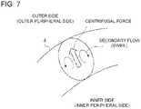
- the flow amount decreases in the region on the outer side, in the bend direction, where a centrifugal force has a strong influence, and development of the secondary flow is suppressed by inclination of the wall surface.
- the bend pipe portion has, at least in a partial section, a flattened shape in which a flow passage width in a direction J orthogonal to the direction I is smaller than a flow passage width in the direction I.
- the flow-passage width in the direction J, of the flow passage width of the bend pipe portion is smaller than the flow-passage width in the direction I, and thereby it is possible to reduce the influence of a centrifugal force. Accordingly, it is possible to suppress a drift to a region on the outer side with respect to the bend direction of the bend pipe, and to suppress occurrence of a secondary flow.
- the flattened shape is an oval shape, a rectangular shape, or a rectangular shape with four rounded corners.
- the flow after passing through the bend pipe portion is guided to the inner side in the bend direction, and thereby it is possible to suppress separation in the inner region.
- the part of the flow toward the inner side hits the side surface on the inner side, the part of the flow may flow backward, provoking local separation on the upstream side.
- a side surface on an inner side with respect to the bend direction of the bend pipe portion includes an inner inclined surface on a downstream side of the outer inclined surface, the inner inclined surface being inclined so that a distance from the line M decreases toward a downstream side.
- the bend pipe is curved so that a part of the flow from the bend pipe portion to the outlet pipe portion flows along the inner inclined surface, and it is possible to suppress a partial reverse flow and local separation as described above.
- a maximum value ⁇ 1 of an inclination angle formed by the outer inclined surface with a line parallel to the line M and a maximum value ⁇ 2 of an inclination angle formed by the inner inclined surface with a line parallel to the line M satisfy ⁇ 1 ⁇ 2.
- a pipe axial center line of the bend pipe portion has a back-side eccentric portion offset from the line M toward the back side and a front-side eccentric portion offset from the line M toward the front side on a downstream side of the back-side eccentric portion.
- the bend pipe in addition to the effect described in the above (3), the bend pipe is curved so that a part of the flow from the bend pipe portion to the outlet pipe portion flows along the inner inclined surface, and it is possible to suppress a partial reverse flow and local separation as described above.
- a distance ⁇ 1 between the line M and a portion of the back-side eccentric portion farthest from the line M toward the back side and a distance ⁇ 2 between the line M and a portion of the front-side eccentric portion farthest from the line M toward the front side satisfy ⁇ 1 ⁇ 2.
- a vertex position at which a flow passage width of each cross section of the bend pipe portion is at a maximum is shifted about a pipe axial center line of the bend pipe portion toward a downstream side.
- a fluid machine includes: an impeller wheel; a casing covering the impeller wheel; an inlet pipe connected to an upstream side of the casing, for guiding a fluid to the impeller wheel; and an outlet pipe connected to a downstream side of the casing, for discharging a fluid after passing through the impeller wheel.
- the inlet pipe or the outlet pipe is the bend pipe according to any one of the above (1) to (13).
- the bend pipe described in any one of the above (1) to (13) is provided, and thus it is possible to suppress development or occurrence of separation in a region on the inner side with respect to the bend direction of the bend pipe. Accordingly, it is possible to improve the efficiency of the fluid machine.
- the above fluid machine (14) is a turbine, an axial flow compressor, or a centrifugal compressor.
- the bend pipe described in any one of the above (1) to (13) is provided, and thus it is possible to suppress development or occurrence of separation in a region on the inner side with respect to the bend direction of the bend pipe. Accordingly, it is possible to improve the turbine efficiency and the compressor efficiency.
- a bend pipe and a fluid machine including the same, whereby it is possible to suppress occurrence of separation in a region on the inner side in the bend direction.
- an expression of relative or absolute arrangement such as “in a direction”, “along a direction”, “parallel”, “orthogonal”, “centered”, “concentric” and “coaxial” shall not be construed as indicating only the arrangement in a strict literal sense, but also includes a state where the arrangement is relatively displaced by a tolerance, or by an angle or a distance whereby it is possible to achieve the same function.
- FIG. 1 is a schematic perspective view of a bend pipe 100 according to an example not falling under claim 1.
- the bend pipe 100 is a bend pipe for supplying a fluid to a fluid machine described below or discharging the fluid from the fluid machine.
- the fluid flowing through the bend pipe 100 is an energy medium used in energy conversion in a fluid machine, which is, for instance a high-pressure gas or a high-pressure fluid.
- the bend pipe 100 includes an inlet pipe portion 2 having a linear shape, a bend pipe portion 4 connected to a downstream end 2a of the inlet pipe portion 2 and configured to change the flow direction of the fluid, and an outlet pipe portion 6 having a linear shape connected to a downstream end 4a of the bend pipe portion 4.
- line L refers to the line including the pipe axial center line of the inlet pipe portion 2 and the extension line thereof
- line M refers to the line including the pipe axial center line of the outlet pipe portion 6 and the extension line thereof
- direction I refers to the direction parallel to an intersection line N formed by a plane orthogonal to the line L and a plane orthogonal to the line M. If the line L and the line M are on the same plane, the direction I is the direction orthogonal to the plane including both of the line L and the line M.
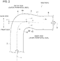
- FIG. 2 is a schematic diagram showing the shape of a bend pipe 100 (100A) according to an embodiment, as seen from the direction I.
- FIG. 3 is a schematic diagram showing the shape of a bend pipe 100 (100B) according to an embodiment, as seen from the direction I.
- FIG. 4 is a schematic diagram showing the shape of a bend pipe 100 (100C) according to an embodiment, as seen from the direction I.
- the side surface 4A of the outer side in the bend direction (the outer side with respect to the curvature radius) of the bend pipe portion 4 includes an outer inclined surface 8 inclined so that the distance d1 from the line M decreases toward the downstream side, on the back side of the line M.
- the direction E of a flow after passing the bend pipe portion 4 is inclined from the line M so as to move inward in the bend direction of the bend pipe 100 toward the downstream side.
- the flow moving in the direction E it is possible to suppress development of a separation flow that occurs in the region on the inner side of the bend direction of the bend pipe 100 by quickly making a separation flow K re-adhere to the inner side, or to suppress occurrence itself of the separation flow K. While an effect to suppress a separation flow is described in FIG. 5 referring to the bend pipe shape shown in FIG. 2 as an example, the same effect can be achieved by the bend pipe shape shown in FIGs. 3 and 4 having the outer inclined surface 8.
- the maximum value ⁇ 1 of the inclination angle formed between the outer inclined surface 8 and the line parallel to the line M is not smaller than 10°. Accordingly, it is possible to increase the inclination of the direction E of the flow after passing the bend pipe portion 4 from the above described line M to some extent, and thus it is possible to suppress development or occurrence of a separation flow in the inner region with respect to the bend direction of the bend pipe 100 with a high effectiveness.
- the pipe axial center line H of the bend pipe portion 4 includes a back-side eccentric portion Hr offset from the line M toward the back side. Accordingly, it is possible to increase the inclination of the direction E of the flow after passing the bend pipe portion 4 from the above described line M more easily, and thus it is possible to suppress development or occurrence of a separation flow in the inner region with respect to the bend direction of the bend pipe 100.
- the distance ⁇ 1 between the line M and a position P on the back-side eccentric portion Hr farthest from the line M toward the back side and the diameter De of the outlet pipe portion 6 satisfy ⁇ 1 ⁇ 0.1De. Accordingly, it is possible to increase the inclination of the direction E of the flow after passing the bend pipe portion 4 from the above described line M to some extent, and thus it is possible to suppress development or occurrence of a separation flow in the inner region with respect to the bend direction of the bend pipe 100 with a high effectiveness.
- the side surface 4B on the inner side with respect to the bend direction of the bend pipe portion 4 may include an inclined surface 12 whose distance d2 from the line M decreases toward the downstream side, and an inclined surface 10 disposed on the downstream side of the inclined surface 12, whose distance d2 from the line M increases toward the downstream side.
- the side surface 4B on the inner side with respect to the bend direction of the bend pipe portion 4 may include an inclined surface 12 whose distance d2 from the line M decreases toward the downstream side, and a non-inclined surface 14 disposed on the downstream side of the inclined surface 12, whose distance d2 from the line M is constant regardless of the position in the flow direction.
- FIG. 6 is a diagram showing a relationship between a pipe axial directional position 'm' and a flow-passage cross-sectional area A of the bend pipe 100 shown in FIG. 3 .
- the flow-passage cross-sectional area in at least one section of the bend pipe portion 4 may be greater than each of the flow-passage cross-sectional area A1 of the inlet pipe portion 2 and the flow-passage cross-sectional area A3 of the outlet pipe portion 6.
- the pressure loss of a fluid in a pipe passage increases in proportion to square of velocity of the fluid.
- the side surface 4B on the inner side with respect to the bend direction of the bend pipe portion 4 may include an inner inclined surface 16 whose distance d2 from the line M decreases toward the downstream side, disposed downstream of the outer inclined surface 8.
- the inner inclined surface 16 is formed continuously on the downstream side of the inclined surface 10 described above.
- the maximum value ⁇ 1 of the inclination angle formed by the outer inclined surface 8 with a line parallel to the line M and the maximum value ⁇ 2 of the inclination angle formed by the inner inclined surface 16 with a line parallel to the line M may satisfy ⁇ 1 ⁇ 2. Accordingly, it is possible to suppress separation effectively over a broad range on the inner side with respect to the bend direction of the bend pipe 100.
- the pipe axial center line H of the bend pipe portion 4 includes a front-side eccentric portion Hf offset from the line M toward the front side, on the downstream side of the back-side eccentric portion Hr. Accordingly, as shown in FIG. 9 , the flow from the bend pipe portion 4 to the outlet pipe portion 6 curves along the inner inclined surface, and it is possible to suppress a partial reverse flow and local separation as described above.
- the distance ⁇ 1 between the line M and a position P on the back-side eccentric portion Hr farthest from the line M toward the back side and the distance ⁇ 2 between the line M and a position Q on the front-side eccentric portion Hf farthest from the line M toward the front side may satisfy ⁇ 1 ⁇ 2. Accordingly, it is possible to suppress separation effectively over a broad range on the inner side with respect to the bend direction of the bend pipe 100.
- FIG. 10 is a diagram showing a relationship between a pipe axial directional position 'm' and a flow-passage cross-sectional area A of the bend pipe 100 shown in FIG. 4 .
- the flow-passage cross-sectional area in at least one section of the bend pipe portion 4 is greater than each of the flow-passage cross-sectional area A1 of the inlet pipe portion 2 and the flow-passage cross-sectional area A3 of the outlet pipe portion 6. Furthermore, in the embodiment shown in FIG. 10 , the flow-passage cross-sectional area of the bend pipe portion 4 reaches the local maximum value A4 at the pipe axial directional position 'm4' on the downstream side of the pipe axial directional position 'm2' at which the flow-passage cross-sectional area of the bend pipe portion 4 reaches its maximum value A2. With the above configuration, it is possible to suppress separation over a broad range on the inner side with respect to the bend direction of the bend pipe 100, and reduce pressure loss.
- FIG. 11 is a diagram showing an example of a flow-passage cross-sectional shape of the bend pipe portion 4 shown in FIGs. 2 to 4 not falling under claim 1.
- FIG. 12 is a diagram showing an example of a flow-passage cross-sectional shape of the bend pipe portion 4 shown in FIGs. 2 to 4 not falling under claim 1.
- FIG. 13 is a diagram showing an example of a flow-passage cross-sectional shape of the bend pipe portion 4 shown in FIGs. 2 to 4 .
- FIG. 14 is a diagram showing an example of a flow-passage cross-sectional shape of the bend pipe portion 4 shown in FIGs. 2 to 4 .
- FIG. 15 is a diagram showing an example of a flow-passage cross-sectional shape of the bend pipe portion 4 shown in FIGs. 2 to 4 .
- the flow-passage cross section of the bend pipe portion 4 may have a circular shape.
- the bend pipe portion 4 may include a cross section in which the gravity center G is positioned on the inner side, with respect to the bend direction, of the center O of the flow-passage width Wb in the direction J orthogonal to the direction I, at least in a partial section. That is, in the cross section of at least a partial section of the bend pipe portion 4, the flow-passage cross-sectional area A2out on the outer side, with respect to the bend direction, of the center O of the flow-passage width Wb may be smaller than the flow-passage cross-sectional area A2in on the inner side, with respect to the bend direction, of the center O.
- the flow is likely to deflect outward with respect to the bend direction, which may cause pressure loss.
- the bend pipe portion 4 including a cross section in which the gravity center G is positioned on the inner side, with respect to the bend direction, of the center O of the flow-passage width Wb as described above, the fluid is less likely to flow into a region on the outer side, with respect to the bend direction, of the center O of the bend pipe portion 4, while the fluid is more likely to flow into a region on the inner side, with respect to the bend direction, of the center O.
- separation is reduced, and it is possible to reduce pressure loss in the bend pipe portion 4.
- the flow amount decreases in the region on the outer side, with respect to the bend direction, where a centrifugal force has a strong influence, and development of the secondary flow (see FIG. 7 ) is suppressed by inclination of the wall surface 18.
- the bend pipe portion 4 has a flattened shape in which the flow-passage width Wb in the direction J orthogonal to the direction I is smaller than the flow-passage width Wa in the direction I, at least in a partial section.
- the flattened shape may be an oval shape as shown in FIG. 13A, or a rectangular shape as shown in FIG. 14 , or a rectangular with rounded corners as shown in FIG. 15 .
- the flattened shape is not particularly limited, and may be a polygonal shape such as a diamond shape and a trapezoidal shape, or one of these shapes with rounded corners.
- the flow-passage width Wb in the direction J is smaller than the flow-passage width Wa in the direction I, and thereby it is possible to reduce the influence of a centrifugal force. Accordingly, it is possible to suppress a drift to a region on the outer side with respect to the bend direction, and to suppress occurrence of a secondary flow.
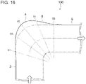
- FIG. 16 is a schematic diagram showing the shape of a bend pipe 100 according to an embodiment, as seen from the direction I.
- FIG. 17 is a diagram showing an example of cross sections S1 to S5 of the bend pipe portion 4 at a plurality of positions (pipe axial directional positions) in the flow direction shown in FIG. 16 , the example not falling under claim 1.
- FIG. 18 is a diagram showing an example of cross sections S1 to S5 of the bend pipe portion 4 at a plurality of positions (pipe axial directional positions) in the flow direction shown in FIG. 16 , the example not falling under claim 1.
- the cross sections S1 to S5 are cross sections as seen from the downstream side in the flow direction.
- the vertex position V at which the flow-passage width reaches its maximum in each of the cross sections S1 to S5 of the bend pipe portion 4 may be constant regardless of the position in the flow direction. Accordingly, it is possible to form the above described outer inclined surface 8 with a simple shape.
- the vertex position V at which the flow-passage width in each cross section of the bend pipe portion 4 reaches its maximum may shift along the rotational direction C of the flow about the axis toward the downstream side. Accordingly, even in a case where a flow that flows from the inlet pipe portion 2 originally has a rotation component, it is possible to suppress occurrence of separation effectively in a region on the inner side with respect to the bend direction of the bend pipe 100.
- the bend pipe 100 described above may be applied to an inlet pipe 22 (intake chamber) of a turbine 20 as a fluid machine. That is, as shown in FIG. 20 , in the turbine 20 including an impeller wheel 24, a turbine casing 26 covering the impeller wheel 24, and an inlet pipe 22 connected to the upstream side of the turbine casing 26 for guiding a fluid to the impeller wheel 24, the inlet pipe 22 may be the bend pipe 100.
- the bend pipe 100 described above may be applied to an outlet pipe 28 (exhaust chamber) of a turbine 20 as a fluid machine. That is, as shown in FIG. 21 , in the turbine 20 including an impeller wheel 24, a turbine casing 26 covering the impeller wheel 24, and an outlet pipe 28 connected to the downstream side of the turbine casing 26 for discharging a fluid after passing through the impeller wheel 24, the outlet pipe 28 may be the bend pipe 100.
- the bend pipe 100 described above may be applied to an inlet pipe 32 (intake chamber) of an axial flow compressor 30 serving as a fluid machine. That is, as shown in FIG. 22 , in the axial flow compressor 30 including an impeller wheel 34, a compressor casing 36 covering the impeller wheel 34, and an inlet pipe 32 connected to the upstream side of the compressor casing 36 for guiding a fluid to the impeller wheel 34, the inlet pipe 32 may be the bend pipe 100.
- the bend pipe 100 described above may be applied to an outlet pipe 38 (exhaust chamber) of an axial flow compressor 30 serving as a fluid machine. That is, as shown in FIG. 23 , in the axial flow compressor 30 including an impeller wheel 34, a compressor casing 36 covering the impeller wheel 34, and an outlet pipe 38 connected to the downstream side of the compressor casing 36 for discharging a fluid after passing through the impeller wheel 34, the outlet pipe 38 may be the bend pipe 100.
- the bend pipe 100 described above may be applied to an inlet pipe 42 of a centrifugal compressor 40 serving as a fluid machine. That is, as shown in FIG. 24 , in the centrifugal compressor 40 including an impeller wheel 44, a compressor casing 46 covering the impeller wheel 44, and an inlet pipe 42 connected to the upstream side of the compressor casing 46 for guiding a fluid to the impeller wheel 44, the inlet pipe 42 may be the bend pipe 100.
- the bend pipe 100 described above may be applied to an outlet pipe 48 (discharge scroll) of a centrifugal compressor 40 serving as a fluid machine. That is, as shown in FIG. 25 , in the centrifugal compressor 40 including an impeller wheel 44, a compressor casing 46 (see FIG. 24 ) covering the impeller wheel 44, and an outlet pipe 48 connected to the downstream side of the compressor casing 46 for discharging a fluid after passing through the impeller wheel 44, the outlet pipe 48 may be the bend pipe 100.
Landscapes
- Engineering & Computer Science (AREA)
- General Engineering & Computer Science (AREA)
- Mechanical Engineering (AREA)
- Branch Pipes, Bends, And The Like (AREA)
- Structures Of Non-Positive Displacement Pumps (AREA)
Claims (12)
- Tuyau incurvé (100) pour fournir un fluide à une machine de fluide ou évacuer le fluide de la machine de fluide, le tuyau incurvé comprenant :une portion de tuyau d'entrée (2) présentant une forme linéaire ;une portion de tuyau incurvé (4) reliée à une extrémité en aval de la portion de tuyau d'entrée (2) et configurée pour changer une direction de flux du fluide ; etune portion de tuyau de sortie (6) présentant une forme linéaire reliée à une extrémité en aval de la portion de tuyau incurvé (4),dans lequel, à condition que : une ligne incluant une ligne centrale axiale de tuyau de la portion de tuyau d'entrée (2) et une ligne d'extension de celui-ci est définie comme une ligne L ; une ligne incluant une ligne axiale de tuyau de la portion de tuyau de sortie (6) et une ligne d'extension de celui-ci est définie comme une ligne M ; et une direction parallèle à une ligne d'intersection formée par un plan orthogonal à la ligne L et un plan orthogonal à la ligne M est définie comme une direction I,lorsque, vu depuis la direction I, un côté de la ligne M, sur lequel la portion de tuyau d'entrée (2) existe, est défini comme un côté avant et un côté de la ligne M, sur lequel la portion de tuyau d'entrée (2) n'existe pas, est défini comme un côté arrière,une surface latérale sur un côté extérieur par rapport à une direction incurvée de la portion de tuyau incurvé (4) inclut une surface inclinée extérieure (8) sur le côté arrière de la ligne M, la surface inclinée extérieure (8) étant inclinée de sorte qu'une distance de la ligne M diminue vers un côté en aval,dans lequel une ligne centrale axiale de tuyau de la portion de tuyau incurvé (4) présente une portion excentrique côté arrière décalée de la ligne M vers le côté arrière, et caractérisé en ce quela portion de tuyau incurvé (4) présente, au moins dans une section partielle, une forme aplatie dans laquelle une largeur de passage de flux dans une direction J orthogonale à la direction I est inférieure à une largeur de passage de flux dans la direction I.
- Tuyau incurvé selon la revendication 1,
dans lequel la forme aplatie est une forme ovale, une forme rectangulaire, ou une forme rectangulaire avec quatre coins arrondis. - Tuyau incurvé selon la revendication 1 ou 2,
dans lequel une surface latérale sur un côté intérieur par rapport à la direction incurvée de la portion de tuyau incurvé (4) inclut une surface inclinée intérieure (16) sur un côté en aval de la surface inclinée extérieure (8), la surface inclinée intérieure (16) étant inclinée de sorte qu'une distance de la ligne M diminue vers un côté en aval. - Tuyau incurvé selon la revendication 3,
dans lequel, vu depuis la direction I, une valeur maximum al d'un angle d'inclinaison formé par la surface inclinée extérieure (8) avec une ligne parallèle à la ligne M et une valeur maximum α2 d'un angle d'inclinaison formé par la surface inclinée intérieure (16) avec une ligne parallèle à la ligne M satisfont à α1≥α2. - Tuyau incurvé selon la revendication 3 ou 4,
dans lequel une ligne centrale axiale de tuyau de la portion de tuyau incurvé (6) présente une portion excentrique côté arrière (Hr) décalée de la ligne M vers le côté arrière et une portion excentrique côté avant (Hr) décalée de la ligne M vers le côté avant sur un côté en aval de la portion excentrique côté arrière (Hr). - Tuyau incurvé selon la revendication 5,
dans lequel une distance δ1 entre la ligne M et une portion de la portion excentrique côté arrière (Hr) le plus loin de la ligne M vers le côté arrière et une distance δ2 entre la ligne M et une portion de la portion excentrique côté avant (Hr) le plus loin de la ligne M vers le côté avant satisfont à δ1≥ δ2. - Tuyau incurvé selon l'une quelconque des revendications 1 à 6,
dans lequel, vu depuis la direction I, une valeur maximum al d'un angle d'inclinaison formé par la surface inclinée extérieure (8) avec une ligne parallèle à la ligne M n'est pas inférieure à 10°. - Tuyau incurvé selon l'une quelconque des revendications 1 à 7,
dans lequel un diamètre De de la portion de tuyau de sortie et une distance δ1 entre la ligne M et une portion de la portion excentrique côté arrière (Hr) le plus loin de la ligne M vers le côté arrière satisfont à δ1≥0,1De. - Tuyau incurvé selon l'une quelconque des revendications 1 à 8,
dans lequel une superficie de section de passage de flux au moins dans une section partielle de la portion de tuyau incurvé (4) est supérieure à une superficie de section de passage de flux Al de la portion de tuyau d'entrée (2), et est supérieure à une superficie de section de passage de flux A3 de la portion de tuyau de sortie (6). - Tuyau incurvé selon l'une quelconque des revendications 1 à 9,
dans lequel, au moins dans une section partielle de la portion de tuyau incurvé, une position de sommet (V) dans laquelle une largeur de passage de flux de chaque section transversale de la portion de tuyau incurvé (4) est à un maximum, est déplacée autour d'une ligne centrale axiale de tuyau de la portion de tuyau incurvé (4) vers un côté en aval. - Machine de fluide, comprenant :une roue à aubes (34) ;un boîtier (46) couvrant la roue à aubes (34) ;un tuyau d'entrée (42) relié à un côté en amont du boîtier (46), pour le guidage d'un fluide à la roue à aubes (34) ; etun tuyau de sortie (48) relié à un côté en aval du boîtier (46), pour l'évacuation d'un fluide après le passage à travers la roue à aubes (34),dans lequel le tuyau d'entrée (42) ou le tuyau de sortie (48) comprend le tuyau incurvé (100) selon l'une quelconque des revendications 1 à 10.
- Machine de fluide selon la revendication 11, comprenant une turbine (20), un compresseur de flux axial (30), ou un compresseur centrifuge (40).
Priority Applications (1)
| Application Number | Priority Date | Filing Date | Title |
|---|---|---|---|
| EP20182247.5A EP3736482B1 (fr) | 2015-12-25 | 2015-12-25 | Tuyau incurvé et machine à fluide le comprenant |
Applications Claiming Priority (3)
| Application Number | Priority Date | Filing Date | Title |
|---|---|---|---|
| EP15911387.7A EP3369982B1 (fr) | 2015-12-25 | 2015-12-25 | Tuyau incurvé et machine à fluide le comprenant |
| PCT/JP2015/086279 WO2017109950A1 (fr) | 2015-12-25 | 2015-12-25 | Tuyau incurvé et machine à fluide le comprenant |
| EP20182247.5A EP3736482B1 (fr) | 2015-12-25 | 2015-12-25 | Tuyau incurvé et machine à fluide le comprenant |
Related Parent Applications (2)
| Application Number | Title | Priority Date | Filing Date |
|---|---|---|---|
| EP15911387.7A Division EP3369982B1 (fr) | 2015-12-25 | 2015-12-25 | Tuyau incurvé et machine à fluide le comprenant |
| EP15911387.7A Division-Into EP3369982B1 (fr) | 2015-12-25 | 2015-12-25 | Tuyau incurvé et machine à fluide le comprenant |
Publications (2)
| Publication Number | Publication Date |
|---|---|
| EP3736482A1 EP3736482A1 (fr) | 2020-11-11 |
| EP3736482B1 true EP3736482B1 (fr) | 2022-06-08 |
Family
ID=59089801
Family Applications (2)
| Application Number | Title | Priority Date | Filing Date |
|---|---|---|---|
| EP15911387.7A Active EP3369982B1 (fr) | 2015-12-25 | 2015-12-25 | Tuyau incurvé et machine à fluide le comprenant |
| EP20182247.5A Active EP3736482B1 (fr) | 2015-12-25 | 2015-12-25 | Tuyau incurvé et machine à fluide le comprenant |
Family Applications Before (1)
| Application Number | Title | Priority Date | Filing Date |
|---|---|---|---|
| EP15911387.7A Active EP3369982B1 (fr) | 2015-12-25 | 2015-12-25 | Tuyau incurvé et machine à fluide le comprenant |
Country Status (5)
| Country | Link |
|---|---|
| US (1) | US11435020B2 (fr) |
| EP (2) | EP3369982B1 (fr) |
| JP (1) | JP6605041B2 (fr) |
| CN (1) | CN108700241B (fr) |
| WO (1) | WO2017109950A1 (fr) |
Families Citing this family (4)
| Publication number | Priority date | Publication date | Assignee | Title |
|---|---|---|---|---|
| CN109282105A (zh) * | 2018-11-29 | 2019-01-29 | 中国船舶重工集团公司第七0四研究所 | 附有导流板的球肘减振弯头 |
| JP7593863B2 (ja) * | 2021-03-31 | 2024-12-03 | 本田技研工業株式会社 | 屈曲管 |
| CN113290169B (zh) * | 2021-04-19 | 2023-08-25 | 四川川交路桥有限责任公司 | 一种钢筋加工用弯拱装置 |
| CN116379046B (zh) * | 2023-03-23 | 2026-02-06 | 中建三局第一建设安装有限公司 | 一种减小冷却通道中u型管压降的结构及方法 |
Citations (1)
| Publication number | Priority date | Publication date | Assignee | Title |
|---|---|---|---|---|
| WO2009127192A1 (fr) * | 2008-04-17 | 2009-10-22 | Naber Holding Gmbh & Co. Kg | Coude tubulaire à écoulement optimisé |
Family Cites Families (14)
| Publication number | Priority date | Publication date | Assignee | Title |
|---|---|---|---|---|
| US2056782A (en) * | 1934-08-22 | 1936-10-06 | Carl H Crawford | Conduit structure bend |
| US2837810A (en) * | 1955-06-17 | 1958-06-10 | Flexonics Corp | Method of producing fittings |
| FR1278649A (fr) * | 1960-10-27 | 1961-12-15 | Coude pour canalisations | |
| JPS59180090U (ja) * | 1983-05-18 | 1984-12-01 | 積水化学工業株式会社 | 曲管 |
| JPS61215890A (ja) * | 1985-03-20 | 1986-09-25 | 堀井 清之 | ベンド管 |
| JPS6439426U (fr) | 1987-09-04 | 1989-03-09 | ||
| WO1998015769A1 (fr) | 1996-10-07 | 1998-04-16 | Fmc Corporation | Conception de tube coude a faible usure par erosion |
| JP2002525525A (ja) * | 1998-09-21 | 2002-08-13 | ドン リム インダストリアル カンパニー,リミティド | 高速粒子を含む流れのための耐磨耗性配管付属品 |
| JP4311167B2 (ja) * | 2003-11-11 | 2009-08-12 | 株式会社日立プラントテクノロジー | 軸流型ポンプ |
| WO2005054737A1 (fr) * | 2003-11-29 | 2005-06-16 | Swagelok Company | Conduite de liquide a flux ameliore |
| US6951354B1 (en) * | 2003-12-22 | 2005-10-04 | Pelletron Corporation | Elbow fitting for pneumatic transport system |
| JP2006307740A (ja) | 2005-04-28 | 2006-11-09 | Toshiba Corp | 水力機械の吸出し管および水力機械 |
| CN100482996C (zh) * | 2005-12-29 | 2009-04-29 | 中国人民解放军总后勤部建筑工程研究所 | 一种输水软管及制造方法 |
| CN102971465A (zh) | 2010-06-29 | 2013-03-13 | 沃尔沃建造设备有限公司 | 用于建筑机械驾驶室顶的防水垫圈 |
-
2015
- 2015-12-25 EP EP15911387.7A patent/EP3369982B1/fr active Active
- 2015-12-25 WO PCT/JP2015/086279 patent/WO2017109950A1/fr not_active Ceased
- 2015-12-25 US US15/779,337 patent/US11435020B2/en active Active
- 2015-12-25 CN CN201580084918.1A patent/CN108700241B/zh active Active
- 2015-12-25 EP EP20182247.5A patent/EP3736482B1/fr active Active
- 2015-12-25 JP JP2017557630A patent/JP6605041B2/ja active Active
Patent Citations (1)
| Publication number | Priority date | Publication date | Assignee | Title |
|---|---|---|---|---|
| WO2009127192A1 (fr) * | 2008-04-17 | 2009-10-22 | Naber Holding Gmbh & Co. Kg | Coude tubulaire à écoulement optimisé |
Also Published As
| Publication number | Publication date |
|---|---|
| CN108700241B (zh) | 2021-07-30 |
| US11435020B2 (en) | 2022-09-06 |
| JP6605041B2 (ja) | 2019-11-13 |
| EP3736482A1 (fr) | 2020-11-11 |
| US20180306365A1 (en) | 2018-10-25 |
| WO2017109950A1 (fr) | 2017-06-29 |
| CN108700241A (zh) | 2018-10-23 |
| EP3369982A4 (fr) | 2018-10-17 |
| EP3369982A1 (fr) | 2018-09-05 |
| EP3369982B1 (fr) | 2022-03-09 |
| JPWO2017109950A1 (ja) | 2018-06-28 |
Similar Documents
| Publication | Publication Date | Title |
|---|---|---|
| US8303258B2 (en) | Fan platform fin | |
| CN101563526B (zh) | 用于涡轮机的扩散器和排放系统 | |
| EP2476868B1 (fr) | Système d'échappement pour turbine à vapeur | |
| EP3736482B1 (fr) | Tuyau incurvé et machine à fluide le comprenant | |
| JP6352936B2 (ja) | ねじられた戻り流路ベーンを備える遠心圧縮機 | |
| US20180347382A1 (en) | Centrifugal compressor and turbocharger | |
| EP2474743B1 (fr) | Pompe à baril à étages multiples | |
| EP3299635B1 (fr) | Carter en spirale et compresseur centrifuge | |
| CN104040256A (zh) | 包括旋流器的分离装置 | |
| US11149588B2 (en) | Exhaust chamber of steam turbine, flow guide for steam turbine exhaust chamber, and steam turbine | |
| US10655637B2 (en) | Scroll casing and centrifugal compressor | |
| US20170268347A1 (en) | Turbine blade | |
| US11131217B2 (en) | Steam turbine exhaust chamber and steam turbine | |
| JP4505523B2 (ja) | 遠心型圧縮機のアキシャルディフューザ | |
| CN104632704B (zh) | 立轴泵 | |
| CN113906222B (zh) | 用于离心式压缩机的定子叶片 | |
| JP5905059B2 (ja) | 渦巻ポンプ | |
| JP2017031947A (ja) | 低圧蒸気タービン構造 |
Legal Events
| Date | Code | Title | Description |
|---|---|---|---|
| PUAI | Public reference made under article 153(3) epc to a published international application that has entered the european phase |
Free format text: ORIGINAL CODE: 0009012 |
|
| STAA | Information on the status of an ep patent application or granted ep patent |
Free format text: STATUS: REQUEST FOR EXAMINATION WAS MADE |
|
| 17P | Request for examination filed |
Effective date: 20200625 |
|
| AC | Divisional application: reference to earlier application |
Ref document number: 3369982 Country of ref document: EP Kind code of ref document: P |
|
| AK | Designated contracting states |
Kind code of ref document: A1 Designated state(s): AL AT BE BG CH CY CZ DE DK EE ES FI FR GB GR HR HU IE IS IT LI LT LU LV MC MK MT NL NO PL PT RO RS SE SI SK SM TR |
|
| STAA | Information on the status of an ep patent application or granted ep patent |
Free format text: STATUS: EXAMINATION IS IN PROGRESS |
|
| 17Q | First examination report despatched |
Effective date: 20210401 |
|
| GRAP | Despatch of communication of intention to grant a patent |
Free format text: ORIGINAL CODE: EPIDOSNIGR1 |
|
| STAA | Information on the status of an ep patent application or granted ep patent |
Free format text: STATUS: GRANT OF PATENT IS INTENDED |
|
| RAP3 | Party data changed (applicant data changed or rights of an application transferred) |
Owner name: MITSUBISHI HEAVY INDUSTRIES ENGINE & TURBOCHARGER, LTD. |
|
| INTG | Intention to grant announced |
Effective date: 20220223 |
|
| GRAS | Grant fee paid |
Free format text: ORIGINAL CODE: EPIDOSNIGR3 |
|
| GRAA | (expected) grant |
Free format text: ORIGINAL CODE: 0009210 |
|
| STAA | Information on the status of an ep patent application or granted ep patent |
Free format text: STATUS: THE PATENT HAS BEEN GRANTED |
|
| AC | Divisional application: reference to earlier application |
Ref document number: 3369982 Country of ref document: EP Kind code of ref document: P |
|
| AK | Designated contracting states |
Kind code of ref document: B1 Designated state(s): AL AT BE BG CH CY CZ DE DK EE ES FI FR GB GR HR HU IE IS IT LI LT LU LV MC MK MT NL NO PL PT RO RS SE SI SK SM TR |
|
| REG | Reference to a national code |
Ref country code: AT Ref legal event code: REF Ref document number: 1497159 Country of ref document: AT Kind code of ref document: T Effective date: 20220615 Ref country code: CH Ref legal event code: EP |
|
| REG | Reference to a national code |
Ref country code: DE Ref legal event code: R096 Ref document number: 602015079435 Country of ref document: DE |
|
| REG | Reference to a national code |
Ref country code: IE Ref legal event code: FG4D |
|
| REG | Reference to a national code |
Ref country code: LT Ref legal event code: MG9D |
|
| REG | Reference to a national code |
Ref country code: NL Ref legal event code: MP Effective date: 20220608 |
|
| PG25 | Lapsed in a contracting state [announced via postgrant information from national office to epo] |
Ref country code: SE Free format text: LAPSE BECAUSE OF FAILURE TO SUBMIT A TRANSLATION OF THE DESCRIPTION OR TO PAY THE FEE WITHIN THE PRESCRIBED TIME-LIMIT Effective date: 20220608 Ref country code: NO Free format text: LAPSE BECAUSE OF FAILURE TO SUBMIT A TRANSLATION OF THE DESCRIPTION OR TO PAY THE FEE WITHIN THE PRESCRIBED TIME-LIMIT Effective date: 20220908 Ref country code: LT Free format text: LAPSE BECAUSE OF FAILURE TO SUBMIT A TRANSLATION OF THE DESCRIPTION OR TO PAY THE FEE WITHIN THE PRESCRIBED TIME-LIMIT Effective date: 20220608 Ref country code: HR Free format text: LAPSE BECAUSE OF FAILURE TO SUBMIT A TRANSLATION OF THE DESCRIPTION OR TO PAY THE FEE WITHIN THE PRESCRIBED TIME-LIMIT Effective date: 20220608 Ref country code: GR Free format text: LAPSE BECAUSE OF FAILURE TO SUBMIT A TRANSLATION OF THE DESCRIPTION OR TO PAY THE FEE WITHIN THE PRESCRIBED TIME-LIMIT Effective date: 20220909 Ref country code: FI Free format text: LAPSE BECAUSE OF FAILURE TO SUBMIT A TRANSLATION OF THE DESCRIPTION OR TO PAY THE FEE WITHIN THE PRESCRIBED TIME-LIMIT Effective date: 20220608 Ref country code: BG Free format text: LAPSE BECAUSE OF FAILURE TO SUBMIT A TRANSLATION OF THE DESCRIPTION OR TO PAY THE FEE WITHIN THE PRESCRIBED TIME-LIMIT Effective date: 20220908 |
|
| REG | Reference to a national code |
Ref country code: AT Ref legal event code: MK05 Ref document number: 1497159 Country of ref document: AT Kind code of ref document: T Effective date: 20220608 |
|
| PG25 | Lapsed in a contracting state [announced via postgrant information from national office to epo] |
Ref country code: RS Free format text: LAPSE BECAUSE OF FAILURE TO SUBMIT A TRANSLATION OF THE DESCRIPTION OR TO PAY THE FEE WITHIN THE PRESCRIBED TIME-LIMIT Effective date: 20220608 Ref country code: LV Free format text: LAPSE BECAUSE OF FAILURE TO SUBMIT A TRANSLATION OF THE DESCRIPTION OR TO PAY THE FEE WITHIN THE PRESCRIBED TIME-LIMIT Effective date: 20220608 |
|
| PG25 | Lapsed in a contracting state [announced via postgrant information from national office to epo] |
Ref country code: NL Free format text: LAPSE BECAUSE OF FAILURE TO SUBMIT A TRANSLATION OF THE DESCRIPTION OR TO PAY THE FEE WITHIN THE PRESCRIBED TIME-LIMIT Effective date: 20220608 |
|
| PG25 | Lapsed in a contracting state [announced via postgrant information from national office to epo] |
Ref country code: SM Free format text: LAPSE BECAUSE OF FAILURE TO SUBMIT A TRANSLATION OF THE DESCRIPTION OR TO PAY THE FEE WITHIN THE PRESCRIBED TIME-LIMIT Effective date: 20220608 Ref country code: SK Free format text: LAPSE BECAUSE OF FAILURE TO SUBMIT A TRANSLATION OF THE DESCRIPTION OR TO PAY THE FEE WITHIN THE PRESCRIBED TIME-LIMIT Effective date: 20220608 Ref country code: RO Free format text: LAPSE BECAUSE OF FAILURE TO SUBMIT A TRANSLATION OF THE DESCRIPTION OR TO PAY THE FEE WITHIN THE PRESCRIBED TIME-LIMIT Effective date: 20220608 Ref country code: PT Free format text: LAPSE BECAUSE OF FAILURE TO SUBMIT A TRANSLATION OF THE DESCRIPTION OR TO PAY THE FEE WITHIN THE PRESCRIBED TIME-LIMIT Effective date: 20221010 Ref country code: ES Free format text: LAPSE BECAUSE OF FAILURE TO SUBMIT A TRANSLATION OF THE DESCRIPTION OR TO PAY THE FEE WITHIN THE PRESCRIBED TIME-LIMIT Effective date: 20220608 Ref country code: EE Free format text: LAPSE BECAUSE OF FAILURE TO SUBMIT A TRANSLATION OF THE DESCRIPTION OR TO PAY THE FEE WITHIN THE PRESCRIBED TIME-LIMIT Effective date: 20220608 Ref country code: CZ Free format text: LAPSE BECAUSE OF FAILURE TO SUBMIT A TRANSLATION OF THE DESCRIPTION OR TO PAY THE FEE WITHIN THE PRESCRIBED TIME-LIMIT Effective date: 20220608 Ref country code: AT Free format text: LAPSE BECAUSE OF FAILURE TO SUBMIT A TRANSLATION OF THE DESCRIPTION OR TO PAY THE FEE WITHIN THE PRESCRIBED TIME-LIMIT Effective date: 20220608 |
|
| PG25 | Lapsed in a contracting state [announced via postgrant information from national office to epo] |
Ref country code: PL Free format text: LAPSE BECAUSE OF FAILURE TO SUBMIT A TRANSLATION OF THE DESCRIPTION OR TO PAY THE FEE WITHIN THE PRESCRIBED TIME-LIMIT Effective date: 20220608 Ref country code: IS Free format text: LAPSE BECAUSE OF FAILURE TO SUBMIT A TRANSLATION OF THE DESCRIPTION OR TO PAY THE FEE WITHIN THE PRESCRIBED TIME-LIMIT Effective date: 20221008 |
|
| REG | Reference to a national code |
Ref country code: DE Ref legal event code: R097 Ref document number: 602015079435 Country of ref document: DE |
|
| PG25 | Lapsed in a contracting state [announced via postgrant information from national office to epo] |
Ref country code: AL Free format text: LAPSE BECAUSE OF FAILURE TO SUBMIT A TRANSLATION OF THE DESCRIPTION OR TO PAY THE FEE WITHIN THE PRESCRIBED TIME-LIMIT Effective date: 20220608 |
|
| PLBE | No opposition filed within time limit |
Free format text: ORIGINAL CODE: 0009261 |
|
| STAA | Information on the status of an ep patent application or granted ep patent |
Free format text: STATUS: NO OPPOSITION FILED WITHIN TIME LIMIT |
|
| PG25 | Lapsed in a contracting state [announced via postgrant information from national office to epo] |
Ref country code: DK Free format text: LAPSE BECAUSE OF FAILURE TO SUBMIT A TRANSLATION OF THE DESCRIPTION OR TO PAY THE FEE WITHIN THE PRESCRIBED TIME-LIMIT Effective date: 20220608 |
|
| 26N | No opposition filed |
Effective date: 20230310 |
|
| PG25 | Lapsed in a contracting state [announced via postgrant information from national office to epo] |
Ref country code: SI Free format text: LAPSE BECAUSE OF FAILURE TO SUBMIT A TRANSLATION OF THE DESCRIPTION OR TO PAY THE FEE WITHIN THE PRESCRIBED TIME-LIMIT Effective date: 20220608 |
|
| REG | Reference to a national code |
Ref country code: CH Ref legal event code: PL |
|
| GBPC | Gb: european patent ceased through non-payment of renewal fee |
Effective date: 20221225 |
|
| REG | Reference to a national code |
Ref country code: BE Ref legal event code: MM Effective date: 20221231 |
|
| PG25 | Lapsed in a contracting state [announced via postgrant information from national office to epo] |
Ref country code: LU Free format text: LAPSE BECAUSE OF NON-PAYMENT OF DUE FEES Effective date: 20221225 |
|
| PG25 | Lapsed in a contracting state [announced via postgrant information from national office to epo] |
Ref country code: LI Free format text: LAPSE BECAUSE OF NON-PAYMENT OF DUE FEES Effective date: 20221231 Ref country code: IE Free format text: LAPSE BECAUSE OF NON-PAYMENT OF DUE FEES Effective date: 20221225 Ref country code: GB Free format text: LAPSE BECAUSE OF NON-PAYMENT OF DUE FEES Effective date: 20221225 Ref country code: CH Free format text: LAPSE BECAUSE OF NON-PAYMENT OF DUE FEES Effective date: 20221231 |
|
| PG25 | Lapsed in a contracting state [announced via postgrant information from national office to epo] |
Ref country code: FR Free format text: LAPSE BECAUSE OF NON-PAYMENT OF DUE FEES Effective date: 20221231 Ref country code: BE Free format text: LAPSE BECAUSE OF NON-PAYMENT OF DUE FEES Effective date: 20221231 |
|
| PG25 | Lapsed in a contracting state [announced via postgrant information from national office to epo] |
Ref country code: IT Free format text: LAPSE BECAUSE OF FAILURE TO SUBMIT A TRANSLATION OF THE DESCRIPTION OR TO PAY THE FEE WITHIN THE PRESCRIBED TIME-LIMIT Effective date: 20220608 |
|
| PG25 | Lapsed in a contracting state [announced via postgrant information from national office to epo] |
Ref country code: CY Free format text: LAPSE BECAUSE OF FAILURE TO SUBMIT A TRANSLATION OF THE DESCRIPTION OR TO PAY THE FEE WITHIN THE PRESCRIBED TIME-LIMIT Effective date: 20220608 |
|
| PG25 | Lapsed in a contracting state [announced via postgrant information from national office to epo] |
Ref country code: MK Free format text: LAPSE BECAUSE OF FAILURE TO SUBMIT A TRANSLATION OF THE DESCRIPTION OR TO PAY THE FEE WITHIN THE PRESCRIBED TIME-LIMIT Effective date: 20220608 Ref country code: HU Free format text: LAPSE BECAUSE OF FAILURE TO SUBMIT A TRANSLATION OF THE DESCRIPTION OR TO PAY THE FEE WITHIN THE PRESCRIBED TIME-LIMIT; INVALID AB INITIO Effective date: 20151225 |
|
| PG25 | Lapsed in a contracting state [announced via postgrant information from national office to epo] |
Ref country code: MC Free format text: LAPSE BECAUSE OF FAILURE TO SUBMIT A TRANSLATION OF THE DESCRIPTION OR TO PAY THE FEE WITHIN THE PRESCRIBED TIME-LIMIT Effective date: 20220608 |
|
| PG25 | Lapsed in a contracting state [announced via postgrant information from national office to epo] |
Ref country code: TR Free format text: LAPSE BECAUSE OF FAILURE TO SUBMIT A TRANSLATION OF THE DESCRIPTION OR TO PAY THE FEE WITHIN THE PRESCRIBED TIME-LIMIT Effective date: 20220608 Ref country code: MC Free format text: LAPSE BECAUSE OF FAILURE TO SUBMIT A TRANSLATION OF THE DESCRIPTION OR TO PAY THE FEE WITHIN THE PRESCRIBED TIME-LIMIT Effective date: 20220608 |
|
| PG25 | Lapsed in a contracting state [announced via postgrant information from national office to epo] |
Ref country code: MT Free format text: LAPSE BECAUSE OF FAILURE TO SUBMIT A TRANSLATION OF THE DESCRIPTION OR TO PAY THE FEE WITHIN THE PRESCRIBED TIME-LIMIT Effective date: 20220608 |
|
| PG25 | Lapsed in a contracting state [announced via postgrant information from national office to epo] |
Ref country code: BG Free format text: LAPSE BECAUSE OF FAILURE TO SUBMIT A TRANSLATION OF THE DESCRIPTION OR TO PAY THE FEE WITHIN THE PRESCRIBED TIME-LIMIT Effective date: 20220608 |
|
| PG25 | Lapsed in a contracting state [announced via postgrant information from national office to epo] |
Ref country code: BG Free format text: LAPSE BECAUSE OF FAILURE TO SUBMIT A TRANSLATION OF THE DESCRIPTION OR TO PAY THE FEE WITHIN THE PRESCRIBED TIME-LIMIT Effective date: 20220608 |
|
| PGFP | Annual fee paid to national office [announced via postgrant information from national office to epo] |
Ref country code: DE Payment date: 20251028 Year of fee payment: 11 |