EP3736894B1 - Plaque bipolaire pour piles à combustible, empilement de piles à combustible doté de telles plaques bipolaires ainsi que véhicule doté d'un tel empilement de piles à combustible - Google Patents
Plaque bipolaire pour piles à combustible, empilement de piles à combustible doté de telles plaques bipolaires ainsi que véhicule doté d'un tel empilement de piles à combustible Download PDFInfo
- Publication number
- EP3736894B1 EP3736894B1 EP20155267.6A EP20155267A EP3736894B1 EP 3736894 B1 EP3736894 B1 EP 3736894B1 EP 20155267 A EP20155267 A EP 20155267A EP 3736894 B1 EP3736894 B1 EP 3736894B1
- Authority
- EP
- European Patent Office
- Prior art keywords
- plate
- cathode
- anode
- bipolar
- fuel cell
- Prior art date
- Legal status (The legal status is an assumption and is not a legal conclusion. Google has not performed a legal analysis and makes no representation as to the accuracy of the status listed.)
- Active
Links
Images


Classifications
-
- H—ELECTRICITY
- H01—ELECTRIC ELEMENTS
- H01M—PROCESSES OR MEANS, e.g. BATTERIES, FOR THE DIRECT CONVERSION OF CHEMICAL ENERGY INTO ELECTRICAL ENERGY
- H01M8/00—Fuel cells; Manufacture thereof
- H01M8/02—Details
- H01M8/0202—Collectors; Separators, e.g. bipolar separators; Interconnectors
- H01M8/0258—Collectors; Separators, e.g. bipolar separators; Interconnectors characterised by the configuration of channels, e.g. by the flow field of the reactant or coolant
- H01M8/0265—Collectors; Separators, e.g. bipolar separators; Interconnectors characterised by the configuration of channels, e.g. by the flow field of the reactant or coolant the reactant or coolant channels having varying cross sections
-
- H—ELECTRICITY
- H01—ELECTRIC ELEMENTS
- H01M—PROCESSES OR MEANS, e.g. BATTERIES, FOR THE DIRECT CONVERSION OF CHEMICAL ENERGY INTO ELECTRICAL ENERGY
- H01M8/00—Fuel cells; Manufacture thereof
- H01M8/02—Details
- H01M8/0202—Collectors; Separators, e.g. bipolar separators; Interconnectors
- H01M8/0258—Collectors; Separators, e.g. bipolar separators; Interconnectors characterised by the configuration of channels, e.g. by the flow field of the reactant or coolant
-
- B—PERFORMING OPERATIONS; TRANSPORTING
- B60—VEHICLES IN GENERAL
- B60L—PROPULSION OF ELECTRICALLY-PROPELLED VEHICLES; SUPPLYING ELECTRIC POWER FOR AUXILIARY EQUIPMENT OF ELECTRICALLY-PROPELLED VEHICLES; ELECTRODYNAMIC BRAKE SYSTEMS FOR VEHICLES IN GENERAL; MAGNETIC SUSPENSION OR LEVITATION FOR VEHICLES; MONITORING OPERATING VARIABLES OF ELECTRICALLY-PROPELLED VEHICLES; ELECTRIC SAFETY DEVICES FOR ELECTRICALLY-PROPELLED VEHICLES
- B60L53/00—Methods of charging batteries, specially adapted for electric vehicles; Charging stations or on-board charging equipment therefor; Exchange of energy storage elements in electric vehicles
- B60L53/50—Charging stations characterised by energy-storage or power-generation means
- B60L53/54—Fuel cells
-
- H—ELECTRICITY
- H01—ELECTRIC ELEMENTS
- H01M—PROCESSES OR MEANS, e.g. BATTERIES, FOR THE DIRECT CONVERSION OF CHEMICAL ENERGY INTO ELECTRICAL ENERGY
- H01M8/00—Fuel cells; Manufacture thereof
- H01M8/02—Details
- H01M8/0202—Collectors; Separators, e.g. bipolar separators; Interconnectors
- H01M8/0204—Non-porous and characterised by the material
- H01M8/0206—Metals or alloys
-
- H—ELECTRICITY
- H01—ELECTRIC ELEMENTS
- H01M—PROCESSES OR MEANS, e.g. BATTERIES, FOR THE DIRECT CONVERSION OF CHEMICAL ENERGY INTO ELECTRICAL ENERGY
- H01M8/00—Fuel cells; Manufacture thereof
- H01M8/02—Details
- H01M8/0202—Collectors; Separators, e.g. bipolar separators; Interconnectors
- H01M8/0204—Non-porous and characterised by the material
- H01M8/0213—Gas-impermeable carbon-containing materials
-
- H—ELECTRICITY
- H01—ELECTRIC ELEMENTS
- H01M—PROCESSES OR MEANS, e.g. BATTERIES, FOR THE DIRECT CONVERSION OF CHEMICAL ENERGY INTO ELECTRICAL ENERGY
- H01M8/00—Fuel cells; Manufacture thereof
- H01M8/02—Details
- H01M8/0202—Collectors; Separators, e.g. bipolar separators; Interconnectors
- H01M8/0204—Non-porous and characterised by the material
- H01M8/0223—Composites
- H01M8/0228—Composites in the form of layered or coated products
-
- H—ELECTRICITY
- H01—ELECTRIC ELEMENTS
- H01M—PROCESSES OR MEANS, e.g. BATTERIES, FOR THE DIRECT CONVERSION OF CHEMICAL ENERGY INTO ELECTRICAL ENERGY
- H01M8/00—Fuel cells; Manufacture thereof
- H01M8/02—Details
- H01M8/0202—Collectors; Separators, e.g. bipolar separators; Interconnectors
- H01M8/0247—Collectors; Separators, e.g. bipolar separators; Interconnectors characterised by the form
- H01M8/0254—Collectors; Separators, e.g. bipolar separators; Interconnectors characterised by the form corrugated or undulated
-
- H—ELECTRICITY
- H01—ELECTRIC ELEMENTS
- H01M—PROCESSES OR MEANS, e.g. BATTERIES, FOR THE DIRECT CONVERSION OF CHEMICAL ENERGY INTO ELECTRICAL ENERGY
- H01M8/00—Fuel cells; Manufacture thereof
- H01M8/02—Details
- H01M8/0202—Collectors; Separators, e.g. bipolar separators; Interconnectors
- H01M8/0267—Collectors; Separators, e.g. bipolar separators; Interconnectors having heating or cooling means, e.g. heaters or coolant flow channels
-
- H—ELECTRICITY
- H01—ELECTRIC ELEMENTS
- H01M—PROCESSES OR MEANS, e.g. BATTERIES, FOR THE DIRECT CONVERSION OF CHEMICAL ENERGY INTO ELECTRICAL ENERGY
- H01M8/00—Fuel cells; Manufacture thereof
- H01M8/04—Auxiliary arrangements, e.g. for control of pressure or for circulation of fluids
- H01M8/04007—Auxiliary arrangements, e.g. for control of pressure or for circulation of fluids related to heat exchange
- H01M8/04029—Heat exchange using liquids
-
- H—ELECTRICITY
- H01—ELECTRIC ELEMENTS
- H01M—PROCESSES OR MEANS, e.g. BATTERIES, FOR THE DIRECT CONVERSION OF CHEMICAL ENERGY INTO ELECTRICAL ENERGY
- H01M8/00—Fuel cells; Manufacture thereof
- H01M8/04—Auxiliary arrangements, e.g. for control of pressure or for circulation of fluids
- H01M8/04298—Processes for controlling fuel cells or fuel cell systems
- H01M8/04694—Processes for controlling fuel cells or fuel cell systems characterised by variables to be controlled
- H01M8/04701—Temperature
-
- H—ELECTRICITY
- H01—ELECTRIC ELEMENTS
- H01M—PROCESSES OR MEANS, e.g. BATTERIES, FOR THE DIRECT CONVERSION OF CHEMICAL ENERGY INTO ELECTRICAL ENERGY
- H01M8/00—Fuel cells; Manufacture thereof
- H01M8/24—Grouping of fuel cells, e.g. stacking of fuel cells
- H01M8/2465—Details of groupings of fuel cells
-
- H—ELECTRICITY
- H01—ELECTRIC ELEMENTS
- H01M—PROCESSES OR MEANS, e.g. BATTERIES, FOR THE DIRECT CONVERSION OF CHEMICAL ENERGY INTO ELECTRICAL ENERGY
- H01M8/00—Fuel cells; Manufacture thereof
- H01M8/24—Grouping of fuel cells, e.g. stacking of fuel cells
- H01M8/2465—Details of groupings of fuel cells
- H01M8/2483—Details of groupings of fuel cells characterised by internal manifolds
-
- H—ELECTRICITY
- H01—ELECTRIC ELEMENTS
- H01M—PROCESSES OR MEANS, e.g. BATTERIES, FOR THE DIRECT CONVERSION OF CHEMICAL ENERGY INTO ELECTRICAL ENERGY
- H01M2250/00—Fuel cells for particular applications; Specific features of fuel cell system
- H01M2250/20—Fuel cells in motive systems, e.g. vehicle, ship, plane
-
- Y—GENERAL TAGGING OF NEW TECHNOLOGICAL DEVELOPMENTS; GENERAL TAGGING OF CROSS-SECTIONAL TECHNOLOGIES SPANNING OVER SEVERAL SECTIONS OF THE IPC; TECHNICAL SUBJECTS COVERED BY FORMER USPC CROSS-REFERENCE ART COLLECTIONS [XRACs] AND DIGESTS
- Y02—TECHNOLOGIES OR APPLICATIONS FOR MITIGATION OR ADAPTATION AGAINST CLIMATE CHANGE
- Y02E—REDUCTION OF GREENHOUSE GAS [GHG] EMISSIONS, RELATED TO ENERGY GENERATION, TRANSMISSION OR DISTRIBUTION
- Y02E60/00—Enabling technologies; Technologies with a potential or indirect contribution to GHG emissions mitigation
- Y02E60/30—Hydrogen technology
- Y02E60/50—Fuel cells
-
- Y—GENERAL TAGGING OF NEW TECHNOLOGICAL DEVELOPMENTS; GENERAL TAGGING OF CROSS-SECTIONAL TECHNOLOGIES SPANNING OVER SEVERAL SECTIONS OF THE IPC; TECHNICAL SUBJECTS COVERED BY FORMER USPC CROSS-REFERENCE ART COLLECTIONS [XRACs] AND DIGESTS
- Y02—TECHNOLOGIES OR APPLICATIONS FOR MITIGATION OR ADAPTATION AGAINST CLIMATE CHANGE
- Y02T—CLIMATE CHANGE MITIGATION TECHNOLOGIES RELATED TO TRANSPORTATION
- Y02T10/00—Road transport of goods or passengers
- Y02T10/60—Other road transportation technologies with climate change mitigation effect
- Y02T10/70—Energy storage systems for electromobility, e.g. batteries
-
- Y—GENERAL TAGGING OF NEW TECHNOLOGICAL DEVELOPMENTS; GENERAL TAGGING OF CROSS-SECTIONAL TECHNOLOGIES SPANNING OVER SEVERAL SECTIONS OF THE IPC; TECHNICAL SUBJECTS COVERED BY FORMER USPC CROSS-REFERENCE ART COLLECTIONS [XRACs] AND DIGESTS
- Y02—TECHNOLOGIES OR APPLICATIONS FOR MITIGATION OR ADAPTATION AGAINST CLIMATE CHANGE
- Y02T—CLIMATE CHANGE MITIGATION TECHNOLOGIES RELATED TO TRANSPORTATION
- Y02T10/00—Road transport of goods or passengers
- Y02T10/60—Other road transportation technologies with climate change mitigation effect
- Y02T10/7072—Electromobility specific charging systems or methods for batteries, ultracapacitors, supercapacitors or double-layer capacitors
-
- Y—GENERAL TAGGING OF NEW TECHNOLOGICAL DEVELOPMENTS; GENERAL TAGGING OF CROSS-SECTIONAL TECHNOLOGIES SPANNING OVER SEVERAL SECTIONS OF THE IPC; TECHNICAL SUBJECTS COVERED BY FORMER USPC CROSS-REFERENCE ART COLLECTIONS [XRACs] AND DIGESTS
- Y02—TECHNOLOGIES OR APPLICATIONS FOR MITIGATION OR ADAPTATION AGAINST CLIMATE CHANGE
- Y02T—CLIMATE CHANGE MITIGATION TECHNOLOGIES RELATED TO TRANSPORTATION
- Y02T90/00—Enabling technologies or technologies with a potential or indirect contribution to GHG emissions mitigation
- Y02T90/10—Technologies relating to charging of electric vehicles
- Y02T90/12—Electric charging stations
Definitions
- the invention relates to a bipolar plate for a fuel cell comprising an anode plate with an anode side and a coolant side, with a first structuring for forming an anode flow field being formed on the anode side; a cathode plate with a cathode side and a coolant side, a second structuring for the formation of a cathode flow field being formed on the cathode side; structural elements being arranged between the anode plate and the cathode plate to form a coolant flow field.
- the invention also relates to a fuel cell stack with such bipolar plates and a vehicle that has such a fuel cell stack.
- Fuel cells use the chemical conversion of a fuel with oxygen into water to generate electrical energy.
- fuel cells contain the so-called membrane electrode assembly (MEA) as a core component, which is a structure of an ion-conducting (mostly proton-conducting) membrane and a catalytic electrode (anode and cathode) arranged on both sides of the membrane.
- MEA membrane electrode assembly
- the latter mostly comprise supported precious metals, in particular platinum.
- gas diffusion layers (GDL) can be arranged on both sides of the membrane-electrode arrangement on the sides of the electrodes facing away from the membrane.
- the fuel cell is formed by a large number of MEAs arranged in a stack, the electrical voltages of which add up.
- bipolar plates also flow field or separator plates between the individual membrane-electrode arrangements called
- the bipolar plates ensure electrically conductive contact with the membrane-electrode assemblies.
- the fuel anode operating medium
- hydrogen H 2 or a hydrogen-containing gas mixture is supplied to the anode via an open flow field on the anode side of the bipolar plate, where electrochemical oxidation of H 2 to protons H + takes place with the release of electrons (H 2 ⁇ 2 H + + 2 e - ).
- a (water-bound or water-free) transport of the protons from the anode space into the cathode space takes place via the electrolyte or the membrane, which separates the reaction spaces from one another in a gas-tight manner and insulates them electrically.
- the electrons provided at the anode are fed to the cathode via an electrical line.
- Oxygen or an oxygen-containing gas mixture (for example air) as cathode operating medium is fed to the cathode via an open flow field on the cathode side of the bipolar plate, so that a reduction of O 2 to O 2- takes place while absorbing the electrons (1 ⁇ 2 O 2 + 2 e - ⁇ O 2 - ).
- the oxygen anions in the cathode compartment react with the protons transported across the membrane to form water (O 2- + 2 H + ⁇ H 2 O).
- the fuel cell stack is supplied with its operating media, i.e. the anode operating gas (e.g. hydrogen), the cathode operating gas (e.g. air) and the coolant, via main supply channels that pass through the stack in its entire stacking direction and from which the operating media are fed to the individual cells via the bipolar plates are fed.
- the anode operating gas e.g. hydrogen
- the cathode operating gas e.g. air
- bipolar plates consist of two half-plates that are connected to one another and are structured on both sides. On the sides facing away from each other, there are structures for transporting the operating media and on the sides facing one another, structures are required for the transport of coolant.
- the half-panels must be coordinated with one another, since three separate transport routes must be made available by means of two half-panels. This leads to further boundary conditions which reduce the flexibility of the design of the bipolar plates.
- the half-plates of known bipolar plates are profiled, the profiles interlocking or being nested.
- the fuel cell stack typically has end plates which are connected to one another by means of clamping devices as part of a clamping system. Tensile forces are transmitted by means of the clamping devices, which pull the end plates towards one another and press the individual cells arranged between them, that is to say press them against one another. Compression springs are also part of the tensioning system in order to load the stack evenly and to avoid damage to it.
- DE 103 28 039 A1 discloses a bipolar plate which is composed of structured plates which form spring-elastic deformable structural elements in the active area. When installed, pressure is absorbed by the structural elements and their elastic deformation.
- the invention is based on the object of providing a bipolar plate which at least partially eliminates the disadvantages of a bipolar plate which it has in connection with compression springs.
- the bipolar plate comprises an anode plate with an anode side and a coolant side, a first structuring for forming an anode flow field being formed on an anode side.
- the bipolar plate includes furthermore a cathode plate with a cathode side and a coolant side, a second structuring for forming a cathode flow field being formed on the cathode side.
- Structural elements which contact the coolant sides of the anode plate and the cathode plate, are arranged between the anode plate and the cathode plate to form a coolant flow field.
- the structural elements are made of an elastic material and, when the bipolar plate is not installed, the structural elements have different heights depending on the area of the coolant flow field in which they are arranged.
- the pressure load on the bipolar plate or the flow field (s) for the reactants and the coolant is not the same in all areas, but differs, among other things, depending on the geometric shape of the flow paths and their position in relation to the inflow or outflow area of the respective flow field.
- the structural elements of different heights are arranged in areas, with these having a greater height in areas with a lower pressure load than the structural elements in other areas with a higher pressure load.
- three areas are provided, namely an inflow area, an outflow area and a transition area from the inflow area to the outflow area of the flow field, the height of the structural elements increasing from the inflow area to the outflow area.
- the structural elements make contact with the cathode plate and / or the anode plate, and in the installed state in a fuel cell stack are contacted by all structural elements cathode plate and anode plate, since this is tensioned.
- These structural elements serve as embedded springs in a fuel cell stack with the bipolar plates according to the invention, inter alia, to optimize the compression while increasing structural robustness at the same time.
- the stack height of the fuel cell stack can be reduced in comparison to the prior art, since the compression springs commonly used can be dispensed with.
- These compression springs according to the prior art also do not offer good control of the contact pressure on the active surface of the bipolar plate, and the resulting uneven stack compression can lead to plate breakage. This is avoided by the bipolar plate according to the invention.
- weight can be saved. Deflection of the end plate is also minimized. It is also particularly advantageous that the effects of the penetration of GDL / MEA can be minimized.
- a cost reduction in the plate production can be realized, for example by dispensing with the compression springs and by the possibility of using the form-in-place (FIP) process for large-scale production.
- FIP form-in-place
- the bipolar plate according to the invention apart from the structural elements, preferably consists of a conductive material, preferably carbon-based material, preferably graphite or a composite material made of graphite and carbon.
- a conductive material preferably carbon-based material, preferably graphite or a composite material made of graphite and carbon.
- the use of metal is also planned.
- the structural elements provided according to the invention preferably consist of an elastic, preferably electrically conductive polymer which is stable in the temperature range of fuel cell operation, with at least one structural element preferably being conductive.
- All structural elements are preferably made of the same material, so that the spring properties of the structural elements, apart from the selection of the material, are adjusted by their height.
- the heights of the different structural elements result from the specific requirements in the respective area.
- a height of the structural elements of 440 ⁇ m, 420 ⁇ m and 400 ⁇ m and a width of 500 ⁇ m can be assumed.
- the height of the first and the second structuring are determined independently of the heights of the structural elements. These can range from 125 ⁇ m to 225 ⁇ m.
- Silicones or siloxanes are preferably used, with polydimethylsiloxane being particularly preferred.
- the polymer preferably has an electrical conductivity of> 100 S / cm.
- An electrical resistance is preferably 0.0008 ⁇ cm and the compression modulus is preferably 5 MPa.
- the structural elements are arranged at a distance from one another between the anode plate and the cathode plate, so that the coolant can flow through the coolant flow field of the bipolar plate with the lowest possible pressure losses.
- the structural elements are designed in columnar shape, preferably with a constant cross-section over the entire length of the individual structural element or also with a cross-section that varies over the length, for example with a reduced cross-section in the middle of the structural elements.
- the structural elements can have cross-sectional areas of different sizes distributed over the area of the bipolar plate in order to meet different requirements to meet the spring force in different areas of the bipolar plate.
- the structural elements preferably have a rectangular or square cross section, so that very simple manufacture is possible. Round or oval cross-sections with one or two axes of symmetry are also preferred.
- the structuring of the anode plate and the cathode plate are designed in such a way that at least the contact surface of the structural elements on the other sides of the anode plate and cathode plate is at least partially covered by the structuring in order to distribute the pressure over the entire stack height .
- the first structuring of the anode side and the second structuring of the cathode plate and the structural elements are thus arranged directly one above the other in the stacking direction of the bipolar plates. In this way, damage to the bipolar plate can advantageously be avoided.
- the structural elements can be arranged regularly or irregularly in the coolant flow field with the formation of flow areas in order to avoid pressure losses and to use the necessary spring force as required.
- the structural elements and optionally the structuring with regular arrangement preferably form a grid pattern.
- the structural elements are preferably fixed to at least the anode plate or the cathode plate, for example by gluing, with one-sided fixing being able to facilitate the assembly of the bipolar plates and generally being sufficient. Fixing with the cathode plate carrying the oxidizing agent is preferred here.
- the structural elements are provided arranged on at least one carrier plate.
- This at least one carrier plate is preferably made of the same material as the structural elements and is preferably produced in one piece with the structural elements.
- All structural elements can be arranged on a carrier plate or, depending on the area, on different carrier plates, i.e. all structural elements of one height are located on a separate carrier plate. As a result, the manufacturing effort can advantageously be reduced.
- the carrier plate can either be arranged adjacent to the anode plate or to the cathode plate.
- This advantageous embodiment enables a significantly simplified assembly of the bipolar plate according to the invention.
- adhesive bonding to at least the anode plate and the cathode plate can take place analogously to individual structural elements.
- the flow fields of the anode plate and the cathode plate and the coolant flow field can be configured individually, independently of one another.
- Another aspect of the invention relates to a fuel cell stack which comprises a stack of membrane-electrode arrangements alternately arranged between two end plates and bipolar plates according to the invention.
- the invention also relates to a vehicle which has a fuel cell system with a fuel cell stack according to the invention.
- the vehicle is preferably an electric vehicle in which electrical energy generated by the fuel cell system is used to supply an electric traction motor and / or a traction battery.
- FIG. 1 shows a schematic representation of a fuel cell stack, denoted as a whole by 100, according to the present invention.
- the fuel cell stack 100 is part of a vehicle (not shown further), in particular an electric vehicle, which has an electric traction motor that is supplied with electrical energy by the fuel cell stack 100.
- the fuel cell stack 100 comprises a plurality of alternately lined up (stacked) membrane electrode assemblies 10 and bipolar plates 12 on their flat sides. Overall, therefore, several stacked individual cells 11 form the fuel cell stack 100, with both one of the individual cells 11 and the fuel cell stack 100 in general can be referred to as a fuel cell.
- the fuel cell stack 100 has end plates 18 on both ends. Between the bipolar plates 12 and the respective membrane-electrode arrangements 10, anode and cathode spaces (not shown) are arranged, which are delimited by circumferential seals 20. Among other things, in order to produce the sealing function of the seals 20, the fuel cell stack 100 is pressed together (pressed) in the stacking direction S by means of a clamping system.
- the tensioning system comprises an outer tensioning device 22, as well as elastic structural elements, not visible here, which are arranged in the coolant area of the bipolar plates 12. These are described in more detail below.
- elongated tensile bodies 24 of the external tensioning devices 22 pass on tensile forces between the two end plates 18, so that the end plates 18 are pulled towards one another by means of the tensile bodies 24.
- the tensile bodies 24 extend in a stacking direction S of the fuel cell stack 100.
- FIGS 2 and 3 show a bipolar plate 12 according to the invention according to a first embodiment in different views. A detail of the bipolar plate 12 is shown in each case.
- the bipolar plate 12 here comprises two individual plates, an anode plate 30 and a cathode plate 40.
- the anode plate 30 has an anode side 31 and a coolant side 32, which faces the cathode plate 40.
- the cathode plate 40 has a cathode side 41 and a coolant side 42 facing the anode plate 30.
- elastic structural elements 51a, 51b, 51c which have a different height h, are arranged between the anode plate 30 and the cathode plate 40, in each case on the coolant side 32, 42.
- the height h of the structural elements 51a is less than that of the structural elements 51c in the outflow area C, and in the transition area B the height h of the structural elements 51b lies between those of the other structural elements 51a and 51c.
- the structural elements 51a, 51b, 51c are columnar and have a square cross section. These are evenly distributed and thus form flow paths 52 in the form of a grid network through which a coolant can flow in the longitudinal and transverse directions in relation to a main axis of the bipolar plate 12.
- a first structuring 33 and a second structuring 43, respectively, are provided on the anode side 31 and cathode side 41 facing away from the coolant flow field 50, both of which are designed analogously to the structural elements 51a, 51b, 51c of the coolant flow field 50 and an anode flow field 34 and form a cathode flux field 44. Ie these are columnar with a square cross-section. In addition, they form flow paths 35, 45 for the two reaction media, these being in the Figures 2 to 4 in the stacking direction S are congruent with the structural elements 51a, 51b, 51c.
- the differing sizes of the structural elements 51a, 51b, 51c in the center of the cathode plate 40 in contrast to those at the edges can only be attributed to the section of the biopolar plate 12 shown and is of no technical significance. It is of course possible in principle to dimension the structural elements 51a, 51b, 51c differently and to distribute them unevenly.
- the structural elements 51a, 51b, 51c are fixed, preferably glued, at least on the coolant side 42 of the cathode plate 40.
- FIG 4 again shows a detail of a bipolar plate 12 according to a second embodiment in section.
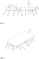
- the structural elements 51a, 51b, 51c are formed in one piece with a carrier plate 53, the flat side of which rests on the coolant side 42 of the cathode plate 40.
- the use of this carrier plate 53 makes the assembly of the bipolar plate 12 much easier.
- fixing can take place, for example by gluing the carrier plate 53 or the structural elements 51a, 51b, 51c.
- FIG Figure 5 The other variant, in which the side of the carrier plate 53 which carries the structural elements 51a, 51b, 51c rests on the coolant side 42 of the cathode plate 40, is shown in FIG Figure 5 shown.
- the anode plate 30 (not shown) is applied to the cathode plate 40 after the carrier plate 53 has been arranged with the structural elements 51a, 51b, 51c in order to complete the bipolar plate 12.
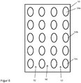
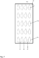
- the Figures 6 and 7th each show a carrier plate 53 with structural elements 51a, 51b, 51c applied to it, which have an oval cross-section with two axes of symmetry ( Figure 6 ) and a cross section with an axis of symmetry ( Figure 7 ). These embodiments serve to optimize the flow conditions of a coolant. These cross-sections can also be selected as the first structuring 33 and / or the second structuring 43.
Landscapes
- Engineering & Computer Science (AREA)
- Chemical & Material Sciences (AREA)
- Life Sciences & Earth Sciences (AREA)
- Sustainable Development (AREA)
- Sustainable Energy (AREA)
- Chemical Kinetics & Catalysis (AREA)
- Manufacturing & Machinery (AREA)
- Electrochemistry (AREA)
- General Chemical & Material Sciences (AREA)
- Power Engineering (AREA)
- Transportation (AREA)
- Mechanical Engineering (AREA)
- Composite Materials (AREA)
- Fuel Cell (AREA)
Claims (10)
- Plaque bipolaire (12) pour pile à combustible, comprenant :une plaque d'anode (30) avec un côté anode (31) et un côté réfrigérant (32), dans laquelle une première structuration (33) permettant de réaliser un champ d'écoulement d'anode (34) est réalisée sur le côté anode (31), etune plaque de cathode (40) avec un côté cathode (41) et un côté réfrigérant (42), dans laquelle une seconde structuration (43) permettant de former un champ d'écoulement de cathode (44) est réalisée sur le côté cathode (41) ;dans laquelle des éléments de structure (51a, 51b, 51c) sont agencés entre la plaque d'anode (30) et la plaque de cathode (40) afin de réaliser un champ d'écoulement de réfrigérant (50),caractérisée en ce que,les éléments de structure (51a, 51b, 51c) consistent en un matériau élastique etles éléments de structure (51a, 51b, 51c) présentent une hauteur différente dans différentes régions du champ d'écoulement de réfrigérant (50) à l'état non assemblé de la plaque bipolaire (12).
- Plaque bipolaire (12) selon la revendication 1, caractérisée en ce que la hauteur (h) des éléments de structure (51a, 51b, 51c) est inversement proportionnelle à la charge de pression dans les régions du champ d'écoulement de réfrigérant (50).
- Plaque bipolaire (12) selon la revendication 1 ou 2, caractérisée en ce que la plaque d'anode (30) et la plaque de cathode (40) consistent en un métal ou un matériau conducteur à base de carbone, de manière préférée du graphite ou un matériau composite à base de graphite et de carbone.
- Plaque bipolaire (12) selon l'une quelconque des revendications 1 à 3, caractérisée en ce que les éléments de structure (51a, 51b, 51c) consistent en un polymère élastique, dans laquelle au moins un élément de structure (51a, 51b, 51c) est électriquement conducteur.
- Plaque bipolaire (12) selon l'une quelconque des revendications précédentes, caractérisée en ce que les éléments de structure (51a, 51b, 51c) sont en forme de colonne et présentent de manière préférée une section transversale rectangulaire ou ovale et sont agencés à distance les uns des autres, et en ce que les structurations (33, 43) de la plaque d'anode (30) et/ou de la plaque de cathode (40) sont éventuellement réalisées en forme de colonne.
- Plaque bipolaire (12) selon l'une quelconque des revendications précédentes, caractérisée en ce que la première structuration (33) de la plaque d'anode (30) et la seconde structuration (43) de la plaque de cathode (40) sont positionnées l'une au-dessus de l'autre dans la direction d'empilement (S) et recouvrent au moins partiellement la surface de section transversale des éléments de structure (51a, 51b, 51c).
- Plaque bipolaire (12) selon l'une quelconque des revendications précédentes, caractérisée en ce que les éléments de structure (51a, 51b, 51c) sont agencés de manière régulière ou irrégulière en réalisant des voies d'écoulement (52).
- Plaque bipolaire (12) selon l'une quelconque des revendications précédentes, caractérisée en ce que les éléments de structure (51a, 51b, 51c) sont fixés à au moins la plaque d'anode (30) ou la plaque de cathode (40), ou en ce que les éléments de structure (51a, 51b, 51c) sont réalisés sur au moins une plaque de support (53) qui est agencée de manière à prendre appui sur la plaque d'anode (30) ou la plaque de cathode (40), dans laquelle ladite plaque de support peut être fixée à la plaque d'anode (30) ou à la plaque de cathode (40).
- Empilement de piles à combustible (100), comprenant un empilement constitué de groupes d'électrodes à membrane (10) et de plaques bipolaires (12) selon l'une quelconque des revendications 1 à 8, agencés de manière alternée entre deux plaques d'extrémité (18).
- Véhicule avec un système de pile à combustible présentant un empilement de piles à combustible (100) selon la revendication 9.
Applications Claiming Priority (1)
| Application Number | Priority Date | Filing Date | Title |
|---|---|---|---|
| DE102019205564.8A DE102019205564A1 (de) | 2019-04-17 | 2019-04-17 | Bipolarplatte für Brennstoffzellen, Brennstoffzellenstapel mit solchen Bipolarplatten sowie Fahrzeug mit einem solchen Brennstoffzellenstapel |
Publications (2)
| Publication Number | Publication Date |
|---|---|
| EP3736894A1 EP3736894A1 (fr) | 2020-11-11 |
| EP3736894B1 true EP3736894B1 (fr) | 2021-08-11 |
Family
ID=69500532
Family Applications (1)
| Application Number | Title | Priority Date | Filing Date |
|---|---|---|---|
| EP20155267.6A Active EP3736894B1 (fr) | 2019-04-17 | 2020-02-04 | Plaque bipolaire pour piles à combustible, empilement de piles à combustible doté de telles plaques bipolaires ainsi que véhicule doté d'un tel empilement de piles à combustible |
Country Status (5)
| Country | Link |
|---|---|
| US (1) | US11688861B2 (fr) |
| EP (1) | EP3736894B1 (fr) |
| JP (1) | JP6861310B2 (fr) |
| CN (1) | CN111834643B (fr) |
| DE (1) | DE102019205564A1 (fr) |
Families Citing this family (3)
| Publication number | Priority date | Publication date | Assignee | Title |
|---|---|---|---|---|
| JP7732883B2 (ja) * | 2021-12-16 | 2025-09-02 | 株式会社Soken | 空冷式燃料電池システム |
| CN114792818A (zh) * | 2022-04-28 | 2022-07-26 | 江苏大学 | 一种冷却开放式燃料电池、冷却系统及冷却方法 |
| CN116190701B (zh) * | 2023-02-09 | 2026-02-03 | 深圳市长盈精密技术股份有限公司 | 一种双极板 |
Family Cites Families (14)
| Publication number | Priority date | Publication date | Assignee | Title |
|---|---|---|---|---|
| CA2352443C (fr) * | 2000-07-07 | 2005-12-27 | Nippon Steel Corporation | Separateurs pour piles a combustible a electrolyte polymerique solide et methode de production de ces produits, et piles a combustible a electrolyte polymerique solide |
| JP3913573B2 (ja) * | 2002-02-26 | 2007-05-09 | 本田技研工業株式会社 | 燃料電池 |
| DE10328039B4 (de) * | 2003-06-18 | 2012-08-02 | Reinz-Dichtungs-Gmbh | Elektrochemische Anordnung mit elastischer Verteilungsstruktur |
| JP5077620B2 (ja) * | 2005-12-16 | 2012-11-21 | トヨタ自動車株式会社 | 燃料電池のセパレータ |
| DE102006041296A1 (de) * | 2006-09-01 | 2008-03-06 | Behr Gmbh & Co. Kg | Scheibenelement für eine Stromabnehmerplatte oder Bipolarplatte einer Brennstoffzelle |
| JP5029813B2 (ja) * | 2007-03-20 | 2012-09-19 | トヨタ自動車株式会社 | 燃料電池用セパレータ |
| DE102008033209A1 (de) * | 2008-07-15 | 2010-01-21 | Daimler Ag | Brennstoffzellenanordnung |
| JP5915971B2 (ja) * | 2012-04-25 | 2016-05-11 | 日産自動車株式会社 | 燃料電池スタック |
| DE102013208450A1 (de) * | 2013-05-08 | 2014-11-13 | Volkswagen Ag | Bipolarplatte, Brennstoffzelllage, Brennstoffzellenstapel und Kraftfahrzeug |
| JP6177296B2 (ja) * | 2015-10-22 | 2017-08-09 | 本田技研工業株式会社 | 燃料電池 |
| DE102015225228A1 (de) * | 2015-11-24 | 2017-05-24 | Volkswagen Aktiengesellschaft | Bipolarplatte für eine Brennstoffzelle sowie Brennstoffzellenstapel mit einer solchen |
| DE102015122264A1 (de) * | 2015-12-18 | 2017-06-22 | Volkswagen Ag | Bipolarplatte für Brennstoffzellen mit optimiertem Design, Brennstoffzellenstapel mit solchen Bipolarplatten sowie Fahrzeug mit einem solchen Brennstoffzellenstapel |
| KR101896321B1 (ko) * | 2016-07-29 | 2018-09-07 | 현대자동차 주식회사 | 응축수가 용이하게 배출되는 연료전지 스택 |
| DE102016121506B4 (de) * | 2016-11-10 | 2024-10-10 | Audi Ag | Bipolarplatte sowie Brennstoffzelle mit einer solchen |
-
2019
- 2019-04-17 DE DE102019205564.8A patent/DE102019205564A1/de not_active Withdrawn
-
2020
- 2020-02-04 EP EP20155267.6A patent/EP3736894B1/fr active Active
- 2020-03-18 JP JP2020047079A patent/JP6861310B2/ja active Active
- 2020-04-16 US US16/851,003 patent/US11688861B2/en active Active
- 2020-04-16 CN CN202010300277.1A patent/CN111834643B/zh active Active
Also Published As
| Publication number | Publication date |
|---|---|
| JP2020177905A (ja) | 2020-10-29 |
| DE102019205564A1 (de) | 2020-10-22 |
| US11688861B2 (en) | 2023-06-27 |
| EP3736894A1 (fr) | 2020-11-11 |
| JP6861310B2 (ja) | 2021-04-21 |
| US20200335803A1 (en) | 2020-10-22 |
| CN111834643B (zh) | 2025-01-07 |
| CN111834643A (zh) | 2020-10-27 |
Similar Documents
| Publication | Publication Date | Title |
|---|---|---|
| DE102015224994B4 (de) | Bipolarplattenstruktur für Brennstoffzellen | |
| EP3378117B1 (fr) | Plaque bipolaire à sections d'étanchéité asymétriques et empilement de piles à combustible muni d'une telle plaque bipolaire | |
| DE102015215231A1 (de) | Bipolarplatte sowie Brennstoffzellensystem mit einer solchen | |
| DE102016121506B4 (de) | Bipolarplatte sowie Brennstoffzelle mit einer solchen | |
| DE102014206333A1 (de) | Bipolarplatte sowie Brennstoffzelle mit einer solchen | |
| WO2017220552A1 (fr) | Plaque bipolaire à largeur variable des canaux à gaz de réaction dans la zone d'entrée de la zone active, empilement de cellules à combustible et système de cellules à combustible comportant de telles plaques bipolaires et véhicule | |
| WO2022128479A1 (fr) | Unité membrane-électrode pour cellule électrochimique et procédé de fabrication d'unité membrane-électrode | |
| EP3736894A1 (fr) | Plaque bipolaire pour piles à combustible, empilement de piles à combustible doté de telles plaques bipolaires ainsi que véhicule doté d'un tel empilement de piles à combustible | |
| DE102015207455A1 (de) | Bipolarplatte mit unterschiedlich dicken Halbplatten und Brennstoffzellenstapel mit einer solchen | |
| DE102016200398A1 (de) | Bipolarplatte für Brennstoffzellen mit drei Einzelplatten, Brennstoffzellenstapel mit solchen Bipolarplatten sowie Fahrzeug mit einem solchen Brennstoffzellenstapel | |
| DE102017215748A1 (de) | Kompressionsvorrichtung für einen Brennstoffzellenstapel | |
| DE102008033209A1 (de) | Brennstoffzellenanordnung | |
| EP3953986B1 (fr) | Plaque bipolaire pour piles à combustible, empilement de piles à combustible avec de telles plaques bipolaires ainsi que véhicule avec un tel empilement de piles à combustible | |
| DE102015223040A1 (de) | Brennstoffzelle sowie Brennstoffzellensystem mit einer solchen | |
| WO2015155125A1 (fr) | Plaque bipolaire et pile à combustible | |
| DE102010054305A1 (de) | Brennstoffzellenstapel mit mehreren Brennstoffzellen | |
| DE102016120535A1 (de) | Brennstoffzelle, Brennstoffzellenstapel und Brennstoffzellensystem | |
| WO2016030095A1 (fr) | Plaque bipolaire et pile à combustible | |
| DE102019206117A1 (de) | Brennstoffzellenstapel umfassend variable Biopolarplatten | |
| DE102018211078B3 (de) | Bipolarplatte für Brennstoffzellen mit drei Einzelplatten, sowie Brennstoffzelle und Brennstoffzellenstapel mit solchen Bipolarplatten | |
| DE102016122587A1 (de) | Polarplatten-Anordnung für eine Brennstoffzelle und Einzelzelle | |
| DE102019205579A1 (de) | Bipolarplatte für Brennstoffzellen, Brennstoffzellenstapel mit solchen Bipolarplatten sowie Fahrzeug mit einem solchen Brennstoffzellenstapel | |
| EP4244923B1 (fr) | Empilement de piles à combustible à structure de tissu compressible | |
| DE102019206118A1 (de) | Bipolarplatte für Brennstoffzellen umfassend elastische elektrodenseitige Strukturelemente | |
| DE102018210165A1 (de) | Spannsystem für Brennstoffzellenstapel und Brennstoffzellenstapel mit einem solchen |
Legal Events
| Date | Code | Title | Description |
|---|---|---|---|
| PUAI | Public reference made under article 153(3) epc to a published international application that has entered the european phase |
Free format text: ORIGINAL CODE: 0009012 |
|
| STAA | Information on the status of an ep patent application or granted ep patent |
Free format text: STATUS: THE APPLICATION HAS BEEN PUBLISHED |
|
| AK | Designated contracting states |
Kind code of ref document: A1 Designated state(s): AL AT BE BG CH CY CZ DE DK EE ES FI FR GB GR HR HU IE IS IT LI LT LU LV MC MK MT NL NO PL PT RO RS SE SI SK SM TR |
|
| AX | Request for extension of the european patent |
Extension state: BA ME |
|
| STAA | Information on the status of an ep patent application or granted ep patent |
Free format text: STATUS: REQUEST FOR EXAMINATION WAS MADE |
|
| 17P | Request for examination filed |
Effective date: 20210401 |
|
| RBV | Designated contracting states (corrected) |
Designated state(s): AL AT BE BG CH CY CZ DE DK EE ES FI FR GB GR HR HU IE IS IT LI LT LU LV MC MK MT NL NO PL PT RO RS SE SI SK SM TR |
|
| GRAP | Despatch of communication of intention to grant a patent |
Free format text: ORIGINAL CODE: EPIDOSNIGR1 |
|
| STAA | Information on the status of an ep patent application or granted ep patent |
Free format text: STATUS: GRANT OF PATENT IS INTENDED |
|
| INTG | Intention to grant announced |
Effective date: 20210514 |
|
| GRAS | Grant fee paid |
Free format text: ORIGINAL CODE: EPIDOSNIGR3 |
|
| GRAA | (expected) grant |
Free format text: ORIGINAL CODE: 0009210 |
|
| STAA | Information on the status of an ep patent application or granted ep patent |
Free format text: STATUS: THE PATENT HAS BEEN GRANTED |
|
| AK | Designated contracting states |
Kind code of ref document: B1 Designated state(s): AL AT BE BG CH CY CZ DE DK EE ES FI FR GB GR HR HU IE IS IT LI LT LU LV MC MK MT NL NO PL PT RO RS SE SI SK SM TR |
|
| REG | Reference to a national code |
Ref country code: CH Ref legal event code: EP |
|
| REG | Reference to a national code |
Ref country code: DE Ref legal event code: R096 Ref document number: 502020000120 Country of ref document: DE |
|
| REG | Reference to a national code |
Ref country code: IE Ref legal event code: FG4D Free format text: LANGUAGE OF EP DOCUMENT: GERMAN Ref country code: AT Ref legal event code: REF Ref document number: 1420314 Country of ref document: AT Kind code of ref document: T Effective date: 20210915 |
|
| REG | Reference to a national code |
Ref country code: LT Ref legal event code: MG9D |
|
| REG | Reference to a national code |
Ref country code: NL Ref legal event code: MP Effective date: 20210811 |
|
| PG25 | Lapsed in a contracting state [announced via postgrant information from national office to epo] |
Ref country code: LT Free format text: LAPSE BECAUSE OF FAILURE TO SUBMIT A TRANSLATION OF THE DESCRIPTION OR TO PAY THE FEE WITHIN THE PRESCRIBED TIME-LIMIT Effective date: 20210811 Ref country code: BG Free format text: LAPSE BECAUSE OF FAILURE TO SUBMIT A TRANSLATION OF THE DESCRIPTION OR TO PAY THE FEE WITHIN THE PRESCRIBED TIME-LIMIT Effective date: 20211111 Ref country code: HR Free format text: LAPSE BECAUSE OF FAILURE TO SUBMIT A TRANSLATION OF THE DESCRIPTION OR TO PAY THE FEE WITHIN THE PRESCRIBED TIME-LIMIT Effective date: 20210811 Ref country code: FI Free format text: LAPSE BECAUSE OF FAILURE TO SUBMIT A TRANSLATION OF THE DESCRIPTION OR TO PAY THE FEE WITHIN THE PRESCRIBED TIME-LIMIT Effective date: 20210811 Ref country code: PT Free format text: LAPSE BECAUSE OF FAILURE TO SUBMIT A TRANSLATION OF THE DESCRIPTION OR TO PAY THE FEE WITHIN THE PRESCRIBED TIME-LIMIT Effective date: 20211213 Ref country code: NO Free format text: LAPSE BECAUSE OF FAILURE TO SUBMIT A TRANSLATION OF THE DESCRIPTION OR TO PAY THE FEE WITHIN THE PRESCRIBED TIME-LIMIT Effective date: 20211111 Ref country code: RS Free format text: LAPSE BECAUSE OF FAILURE TO SUBMIT A TRANSLATION OF THE DESCRIPTION OR TO PAY THE FEE WITHIN THE PRESCRIBED TIME-LIMIT Effective date: 20210811 Ref country code: SE Free format text: LAPSE BECAUSE OF FAILURE TO SUBMIT A TRANSLATION OF THE DESCRIPTION OR TO PAY THE FEE WITHIN THE PRESCRIBED TIME-LIMIT Effective date: 20210811 Ref country code: ES Free format text: LAPSE BECAUSE OF FAILURE TO SUBMIT A TRANSLATION OF THE DESCRIPTION OR TO PAY THE FEE WITHIN THE PRESCRIBED TIME-LIMIT Effective date: 20210811 |
|
| PG25 | Lapsed in a contracting state [announced via postgrant information from national office to epo] |
Ref country code: PL Free format text: LAPSE BECAUSE OF FAILURE TO SUBMIT A TRANSLATION OF THE DESCRIPTION OR TO PAY THE FEE WITHIN THE PRESCRIBED TIME-LIMIT Effective date: 20210811 Ref country code: LV Free format text: LAPSE BECAUSE OF FAILURE TO SUBMIT A TRANSLATION OF THE DESCRIPTION OR TO PAY THE FEE WITHIN THE PRESCRIBED TIME-LIMIT Effective date: 20210811 Ref country code: GR Free format text: LAPSE BECAUSE OF FAILURE TO SUBMIT A TRANSLATION OF THE DESCRIPTION OR TO PAY THE FEE WITHIN THE PRESCRIBED TIME-LIMIT Effective date: 20211112 |
|
| PG25 | Lapsed in a contracting state [announced via postgrant information from national office to epo] |
Ref country code: NL Free format text: LAPSE BECAUSE OF FAILURE TO SUBMIT A TRANSLATION OF THE DESCRIPTION OR TO PAY THE FEE WITHIN THE PRESCRIBED TIME-LIMIT Effective date: 20210811 |
|
| PG25 | Lapsed in a contracting state [announced via postgrant information from national office to epo] |
Ref country code: DK Free format text: LAPSE BECAUSE OF FAILURE TO SUBMIT A TRANSLATION OF THE DESCRIPTION OR TO PAY THE FEE WITHIN THE PRESCRIBED TIME-LIMIT Effective date: 20210811 |
|
| REG | Reference to a national code |
Ref country code: DE Ref legal event code: R097 Ref document number: 502020000120 Country of ref document: DE |
|
| PG25 | Lapsed in a contracting state [announced via postgrant information from national office to epo] |
Ref country code: SM Free format text: LAPSE BECAUSE OF FAILURE TO SUBMIT A TRANSLATION OF THE DESCRIPTION OR TO PAY THE FEE WITHIN THE PRESCRIBED TIME-LIMIT Effective date: 20210811 Ref country code: SK Free format text: LAPSE BECAUSE OF FAILURE TO SUBMIT A TRANSLATION OF THE DESCRIPTION OR TO PAY THE FEE WITHIN THE PRESCRIBED TIME-LIMIT Effective date: 20210811 Ref country code: RO Free format text: LAPSE BECAUSE OF FAILURE TO SUBMIT A TRANSLATION OF THE DESCRIPTION OR TO PAY THE FEE WITHIN THE PRESCRIBED TIME-LIMIT Effective date: 20210811 Ref country code: EE Free format text: LAPSE BECAUSE OF FAILURE TO SUBMIT A TRANSLATION OF THE DESCRIPTION OR TO PAY THE FEE WITHIN THE PRESCRIBED TIME-LIMIT Effective date: 20210811 Ref country code: CZ Free format text: LAPSE BECAUSE OF FAILURE TO SUBMIT A TRANSLATION OF THE DESCRIPTION OR TO PAY THE FEE WITHIN THE PRESCRIBED TIME-LIMIT Effective date: 20210811 Ref country code: AL Free format text: LAPSE BECAUSE OF FAILURE TO SUBMIT A TRANSLATION OF THE DESCRIPTION OR TO PAY THE FEE WITHIN THE PRESCRIBED TIME-LIMIT Effective date: 20210811 |
|
| PLBE | No opposition filed within time limit |
Free format text: ORIGINAL CODE: 0009261 |
|
| STAA | Information on the status of an ep patent application or granted ep patent |
Free format text: STATUS: NO OPPOSITION FILED WITHIN TIME LIMIT |
|
| 26N | No opposition filed |
Effective date: 20220512 |
|
| PG25 | Lapsed in a contracting state [announced via postgrant information from national office to epo] |
Ref country code: IT Free format text: LAPSE BECAUSE OF FAILURE TO SUBMIT A TRANSLATION OF THE DESCRIPTION OR TO PAY THE FEE WITHIN THE PRESCRIBED TIME-LIMIT Effective date: 20210811 |
|
| PG25 | Lapsed in a contracting state [announced via postgrant information from national office to epo] |
Ref country code: MC Free format text: LAPSE BECAUSE OF FAILURE TO SUBMIT A TRANSLATION OF THE DESCRIPTION OR TO PAY THE FEE WITHIN THE PRESCRIBED TIME-LIMIT Effective date: 20210811 |
|
| REG | Reference to a national code |
Ref country code: BE Ref legal event code: MM Effective date: 20220228 |
|
| PG25 | Lapsed in a contracting state [announced via postgrant information from national office to epo] |
Ref country code: LU Free format text: LAPSE BECAUSE OF NON-PAYMENT OF DUE FEES Effective date: 20220204 |
|
| PG25 | Lapsed in a contracting state [announced via postgrant information from national office to epo] |
Ref country code: IE Free format text: LAPSE BECAUSE OF NON-PAYMENT OF DUE FEES Effective date: 20220204 |
|
| PG25 | Lapsed in a contracting state [announced via postgrant information from national office to epo] |
Ref country code: BE Free format text: LAPSE BECAUSE OF NON-PAYMENT OF DUE FEES Effective date: 20220228 |
|
| P01 | Opt-out of the competence of the unified patent court (upc) registered |
Effective date: 20230530 |
|
| REG | Reference to a national code |
Ref country code: CH Ref legal event code: PL |
|
| PG25 | Lapsed in a contracting state [announced via postgrant information from national office to epo] |
Ref country code: LI Free format text: LAPSE BECAUSE OF NON-PAYMENT OF DUE FEES Effective date: 20230228 Ref country code: CH Free format text: LAPSE BECAUSE OF NON-PAYMENT OF DUE FEES Effective date: 20230228 |
|
| PG25 | Lapsed in a contracting state [announced via postgrant information from national office to epo] |
Ref country code: MK Free format text: LAPSE BECAUSE OF FAILURE TO SUBMIT A TRANSLATION OF THE DESCRIPTION OR TO PAY THE FEE WITHIN THE PRESCRIBED TIME-LIMIT Effective date: 20210811 Ref country code: CY Free format text: LAPSE BECAUSE OF FAILURE TO SUBMIT A TRANSLATION OF THE DESCRIPTION OR TO PAY THE FEE WITHIN THE PRESCRIBED TIME-LIMIT Effective date: 20210811 |
|
| PG25 | Lapsed in a contracting state [announced via postgrant information from national office to epo] |
Ref country code: HU Free format text: LAPSE BECAUSE OF FAILURE TO SUBMIT A TRANSLATION OF THE DESCRIPTION OR TO PAY THE FEE WITHIN THE PRESCRIBED TIME-LIMIT; INVALID AB INITIO Effective date: 20200204 |
|
| PG25 | Lapsed in a contracting state [announced via postgrant information from national office to epo] |
Ref country code: MT Free format text: LAPSE BECAUSE OF FAILURE TO SUBMIT A TRANSLATION OF THE DESCRIPTION OR TO PAY THE FEE WITHIN THE PRESCRIBED TIME-LIMIT Effective date: 20210811 |
|
| PGFP | Annual fee paid to national office [announced via postgrant information from national office to epo] |
Ref country code: AT Payment date: 20250417 Year of fee payment: 5 |
|
| PG25 | Lapsed in a contracting state [announced via postgrant information from national office to epo] |
Ref country code: TR Free format text: LAPSE BECAUSE OF FAILURE TO SUBMIT A TRANSLATION OF THE DESCRIPTION OR TO PAY THE FEE WITHIN THE PRESCRIBED TIME-LIMIT Effective date: 20210811 |
|
| PG25 | Lapsed in a contracting state [announced via postgrant information from national office to epo] |
Ref country code: SI Free format text: LAPSE BECAUSE OF FAILURE TO SUBMIT A TRANSLATION OF THE DESCRIPTION OR TO PAY THE FEE WITHIN THE PRESCRIBED TIME-LIMIT Effective date: 20210811 |
|
| PGFP | Annual fee paid to national office [announced via postgrant information from national office to epo] |
Ref country code: GB Payment date: 20260219 Year of fee payment: 7 |
|
| PGFP | Annual fee paid to national office [announced via postgrant information from national office to epo] |
Ref country code: DE Payment date: 20260228 Year of fee payment: 7 |
|
| PG25 | Lapsed in a contracting state [announced via postgrant information from national office to epo] |
Ref country code: AT Free format text: LAPSE BECAUSE OF NON-PAYMENT OF DUE FEES Effective date: 20250204 |
|
| REG | Reference to a national code |
Ref country code: AT Ref legal event code: MM01 Ref document number: 1420314 Country of ref document: AT Kind code of ref document: T Effective date: 20250204 |
|
| PGFP | Annual fee paid to national office [announced via postgrant information from national office to epo] |
Ref country code: FR Payment date: 20260219 Year of fee payment: 7 |