EP3737110A1 - Verfahren und vorrichtung zur verarbeitung von dienstdaten in einem optischen transportnetz - Google Patents
Verfahren und vorrichtung zur verarbeitung von dienstdaten in einem optischen transportnetz Download PDFInfo
- Publication number
- EP3737110A1 EP3737110A1 EP18904680.8A EP18904680A EP3737110A1 EP 3737110 A1 EP3737110 A1 EP 3737110A1 EP 18904680 A EP18904680 A EP 18904680A EP 3737110 A1 EP3737110 A1 EP 3737110A1
- Authority
- EP
- European Patent Office
- Prior art keywords
- service data
- code block
- data
- frame
- code
- Prior art date
- Legal status (The legal status is an assumption and is not a legal conclusion. Google has not performed a legal analysis and makes no representation as to the accuracy of the status listed.)
- Pending
Links
- 230000003287 optical effect Effects 0.000 title claims abstract description 67
- 238000003672 processing method Methods 0.000 title description 3
- 238000000034 method Methods 0.000 claims abstract description 75
- 238000012545 processing Methods 0.000 claims abstract description 36
- 238000013507 mapping Methods 0.000 claims abstract description 25
- 238000013461 design Methods 0.000 description 28
- 238000010586 diagram Methods 0.000 description 26
- 230000007547 defect Effects 0.000 description 14
- 238000004891 communication Methods 0.000 description 11
- 230000005540 biological transmission Effects 0.000 description 10
- 230000006870 function Effects 0.000 description 10
- 230000008569 process Effects 0.000 description 10
- 238000004590 computer program Methods 0.000 description 9
- 238000011144 upstream manufacturing Methods 0.000 description 5
- 238000012544 monitoring process Methods 0.000 description 4
- 238000005516 engineering process Methods 0.000 description 3
- 238000012937 correction Methods 0.000 description 2
- 230000008878 coupling Effects 0.000 description 2
- 238000010168 coupling process Methods 0.000 description 2
- 238000005859 coupling reaction Methods 0.000 description 2
- 125000004122 cyclic group Chemical group 0.000 description 2
- 239000000835 fiber Substances 0.000 description 2
- 230000010354 integration Effects 0.000 description 2
- 238000012423 maintenance Methods 0.000 description 2
- 239000003550 marker Substances 0.000 description 2
- 230000007246 mechanism Effects 0.000 description 2
- 238000012986 modification Methods 0.000 description 2
- 230000004048 modification Effects 0.000 description 2
- 230000001360 synchronised effect Effects 0.000 description 2
- 238000004364 calculation method Methods 0.000 description 1
- 230000008859 change Effects 0.000 description 1
- 230000003993 interaction Effects 0.000 description 1
- 239000013307 optical fiber Substances 0.000 description 1
- 230000009466 transformation Effects 0.000 description 1
- 239000002699 waste material Substances 0.000 description 1
Images







Classifications
-
- H—ELECTRICITY
- H04—ELECTRIC COMMUNICATION TECHNIQUE
- H04L—TRANSMISSION OF DIGITAL INFORMATION, e.g. TELEGRAPHIC COMMUNICATION
- H04L1/00—Arrangements for detecting or preventing errors in the information received
- H04L1/004—Arrangements for detecting or preventing errors in the information received by using forward error control
- H04L1/0056—Systems characterized by the type of code used
- H04L1/0057—Block codes
-
- H—ELECTRICITY
- H04—ELECTRIC COMMUNICATION TECHNIQUE
- H04J—MULTIPLEX COMMUNICATION
- H04J3/00—Time-division multiplex systems
- H04J3/16—Time-division multiplex systems in which the time allocation to individual channels within a transmission cycle is variable, e.g. to accommodate varying complexity of signals, to vary number of channels transmitted
- H04J3/1605—Fixed allocated frame structures
- H04J3/1652—Optical Transport Network [OTN]
-
- H—ELECTRICITY
- H04—ELECTRIC COMMUNICATION TECHNIQUE
- H04B—TRANSMISSION
- H04B10/00—Transmission systems employing electromagnetic waves other than radio-waves, e.g. infrared, visible or ultraviolet light, or employing corpuscular radiation, e.g. quantum communication
- H04B10/50—Transmitters
-
- H—ELECTRICITY
- H04—ELECTRIC COMMUNICATION TECHNIQUE
- H04L—TRANSMISSION OF DIGITAL INFORMATION, e.g. TELEGRAPHIC COMMUNICATION
- H04L1/00—Arrangements for detecting or preventing errors in the information received
- H04L1/0001—Systems modifying transmission characteristics according to link quality, e.g. power backoff
- H04L1/0006—Systems modifying transmission characteristics according to link quality, e.g. power backoff by adapting the transmission format
- H04L1/0007—Systems modifying transmission characteristics according to link quality, e.g. power backoff by adapting the transmission format by modifying the frame length
- H04L1/0008—Systems modifying transmission characteristics according to link quality, e.g. power backoff by adapting the transmission format by modifying the frame length by supplementing frame payload, e.g. with padding bits
-
- H—ELECTRICITY
- H04—ELECTRIC COMMUNICATION TECHNIQUE
- H04L—TRANSMISSION OF DIGITAL INFORMATION, e.g. TELEGRAPHIC COMMUNICATION
- H04L1/00—Arrangements for detecting or preventing errors in the information received
- H04L1/0001—Systems modifying transmission characteristics according to link quality, e.g. power backoff
- H04L1/0009—Systems modifying transmission characteristics according to link quality, e.g. power backoff by adapting the channel coding
- H04L1/0011—Systems modifying transmission characteristics according to link quality, e.g. power backoff by adapting the channel coding applied to payload information
-
- H—ELECTRICITY
- H04—ELECTRIC COMMUNICATION TECHNIQUE
- H04L—TRANSMISSION OF DIGITAL INFORMATION, e.g. TELEGRAPHIC COMMUNICATION
- H04L1/00—Arrangements for detecting or preventing errors in the information received
- H04L1/0001—Systems modifying transmission characteristics according to link quality, e.g. power backoff
- H04L1/0033—Systems modifying transmission characteristics according to link quality, e.g. power backoff arrangements specific to the transmitter
-
- H—ELECTRICITY
- H04—ELECTRIC COMMUNICATION TECHNIQUE
- H04L—TRANSMISSION OF DIGITAL INFORMATION, e.g. TELEGRAPHIC COMMUNICATION
- H04L1/00—Arrangements for detecting or preventing errors in the information received
- H04L1/004—Arrangements for detecting or preventing errors in the information received by using forward error control
- H04L1/0056—Systems characterized by the type of code used
- H04L1/0061—Error detection codes
-
- H—ELECTRICITY
- H04—ELECTRIC COMMUNICATION TECHNIQUE
- H04J—MULTIPLEX COMMUNICATION
- H04J2203/00—Aspects of optical multiplex systems other than those covered by H04J14/05 and H04J14/07
- H04J2203/0001—Provisions for broadband connections in integrated services digital network using frames of the Optical Transport Network [OTN] or using synchronous transfer mode [STM], e.g. SONET, SDH
- H04J2203/0073—Services, e.g. multimedia, GOS, QOS
- H04J2203/0082—Interaction of SDH with non-ATM protocols
- H04J2203/0085—Support of Ethernet
-
- H—ELECTRICITY
- H04—ELECTRIC COMMUNICATION TECHNIQUE
- H04J—MULTIPLEX COMMUNICATION
- H04J3/00—Time-division multiplex systems
- H04J3/02—Details
- H04J3/06—Synchronising arrangements
- H04J3/0635—Clock or time synchronisation in a network
- H04J3/0638—Clock or time synchronisation among nodes; Internode synchronisation
- H04J3/0658—Clock or time synchronisation among packet nodes
- H04J3/0661—Clock or time synchronisation among packet nodes using timestamps
-
- H—ELECTRICITY
- H04—ELECTRIC COMMUNICATION TECHNIQUE
- H04J—MULTIPLEX COMMUNICATION
- H04J3/00—Time-division multiplex systems
- H04J3/16—Time-division multiplex systems in which the time allocation to individual channels within a transmission cycle is variable, e.g. to accommodate varying complexity of signals, to vary number of channels transmitted
- H04J3/1605—Fixed allocated frame structures
- H04J3/1652—Optical Transport Network [OTN]
- H04J3/1658—Optical Transport Network [OTN] carrying packets or ATM cells
-
- H—ELECTRICITY
- H04—ELECTRIC COMMUNICATION TECHNIQUE
- H04Q—SELECTING
- H04Q2213/00—Indexing scheme relating to selecting arrangements in general and for multiplex systems
- H04Q2213/1301—Optical transmission, optical switches
Definitions
- This application relates to the field of optical communications technologies, and in particular, to a method and an apparatus for processing service data in an optical transport network.
- an optical transport network (optical transport network, OTN) includes technical specifications of an electrical layer and an optical layer.
- the optical transport network has abundant operation, administration, and maintenance (operation administration and maintenance, OAM), a powerful tandem connection monitoring (tandem connection monitoring, TCM) capability, and an out-of-band forward error correction (forward error correction, FEC) capability, and can implement flexible scheduling and administration of a large-capacity service.
- OAM operation administration and maintenance
- TCM tandem connection monitoring
- FEC forward error correction
- a slot of a data frame stream of an existing optical transport network is allocated to only a fixed port, and unless reconfigured, the slot transmits only service data from the port. This results in low flexibility.
- Embodiments of this application provide a method and an apparatus for processing service data in an optical transport network, to resolve an existing problem of low flexibility.
- an embodiment of this application provides a method for processing service data in an optical transport network, and the method is applied to a transmitter side and includes: receiving service data, where the service data is to be mapped to a plurality of consecutive data frames; determining a quantity of code blocks, occupied by the service data, of each of the plurality of consecutive data frames and locations of the code blocks, where the code block includes a payload area and an overhead area, the payload area of the code block is used to carry the service data, and the overhead area of the code block includes identification information of the service data; and mapping the service data to the plurality of consecutive data frames based on the quantity of code blocks and the locations of the code blocks.
- a code block of a smaller granularity is defined in a data frame, and a channel identifier field is defined in an overhead area of the code block.
- the channel identifier field is used to carry identification information of service data carried in a payload area.
- the data frame may be a flexible optical transport network (flexible OTN, FlexO) frame or an optical channel data unit (optical channel data unit, ODU) frame
- the ODU frame may be an ODUflex, an ODUk, or the like.
- a rate of the code block is less than or equal to 1 Gbps.
- each FlexO frame may include fixed padding in addition to code blocks.
- each FlexO frame may include fixed padding in addition to code blocks.
- a quantity of bits occupied by one FlexO frame is not enough to be divided exactly by a quantity of bits occupied by code blocks, remaining bits obtained after exact division are used for fixed padding.
- the FlexO frame may not include fixed padding, and a plurality of consecutive FlexO frames constitute one data frame, where the FlexO frame includes a fixed quantity of code blocks.
- a plurality of consecutive FlexO frames may constitute one data frame.
- a quantity of bits occupied in a payload area of one FlexO multiframe can be divided exactly by the quantity of bits occupied by the code blocks.
- the data frame is an ODU frame
- the method may further include: mapping, to at least one FlexO frame, a plurality of consecutive ODU frames that carry the service data.
- a code block of a smaller granularity is defined in an ODU frame.
- code blocks at a same location in a plurality of consecutive ODU frames may be occupied by service data from different ports.
- the ODU frame is more flexibly configured, and then the ODU frame is mapped to a FlexO frame, so that the FlexO frame is transmitted more flexibly.
- the service data is a packet-type service
- the overhead area of the code block further includes an indication field, where the indication field is used to indicate whether the code block carries the service data.
- a receiving node that receives the code block can determine, based on the indication field, whether there is data in the code block, to determine whether to obtain the service data from the code block.
- the service data is a constant bit rate service
- the overhead area of the code block further includes a payload length field
- the payload length field is used to indicate a length of the service data carried by the code block.
- a receiving node that receives the code block can determine, based on the payload length field, the length of the service data carried by the code block, to determine whether to obtain the service data of the length from the code block.
- the overhead area of the code block may further include a timestamp field, and the timestamp field is used to indicate a time at which the service data is mapped to the code block.
- the code block may further include a check area, and the check area of the code block is used to indicate correctness of the service data carried in the payload area of the code block and correctness of content indicated by a field included in the overhead area.
- a receiving node that receives the code block can determine, based on the check area, the correctness of the service data obtained from the code block.
- the overhead area may further include an overhead field, and the overhead field includes at least one of the following:
- an embodiment of this application provides a method for processing service data in an optical transport network, and the method is applied to a receiver side and includes: obtaining a plurality of consecutive data frames, where each of the plurality of consecutive data frames includes a plurality of code blocks, each of the plurality of code blocks includes a payload area and an overhead area, the payload area is used to carry service data, and the overhead area includes identification information of the service data; and identifying code blocks that carry same identification information in the plurality of consecutive data frames, and obtaining, from the code blocks that carry the same identification information, the service data identified by the same identification information.
- a code block of a smaller granularity is defined in a data frame, and a channel identifier field is defined in an overhead area of the code block.
- the channel identifier field is used to carry identification information of service data carried in a payload area.
- Code blocks at a same location in a plurality of consecutive data frames may be occupied by service data from different ports.
- a node on the receiver side identifies service data from a same port by using the channel identifier field, so that flexible configuration of the data frame may be implemented, and data frame transmission flexibility is further improved.
- a rate of the code block is less than or equal to 1 Gbps.
- the data frame is a flexible optical transport network FlexO frame, and the FlexO frame may further include fixed padding.
- each data frame includes a plurality of consecutive FlexO frames, and the plurality of consecutive FlexO frames include the fixed quantity of code blocks.
- the data frame may be an optical data unit ODU frame.
- the service data is a packet-type service
- an overhead area of a first code block further includes an indication field, where the indication field is used to indicate whether the first code block carries the service data, and the first code block is any code block used to carry the service data.
- the service data is a service of a constant bit rate service
- an overhead area of a second code block further includes a payload length field, where the payload length field is used to indicate a length of the service data carried by the second code block, and the second code block is any code block used to carry the service data.
- the overhead area of the second code block further includes a timestamp field, and the timestamp field is used to indicate a time at which the service data identified by the same identification information is mapped to the first code block.
- each code block may further include a check area, and the check area is used to indicate correctness of the service data carried in the payload area of each code block and correctness of content indicated by a field included in the overhead area.
- the overhead area may further include an overhead field, and the overhead field includes at least one of the following:
- an embodiment of this application provides a method for processing service data in an optical transport network, and the method is applied to an intermediate node through which a path passes from a transmitter side to a receiver side and the method includes: obtaining a data frame, where the data frame includes a fixed quantity of code blocks, each code block includes a payload area and an overhead area, the payload area is used to carry service data, the overhead area includes identification information used to identify the service data, and the identification information included in the overhead area is used to indicate a source port from which the service data comes; and updating the identification information included in the overhead area to identification information of a corresponding destination port in a data table, where the data table includes a correspondence between the identification information of the source port and the identification information of the destination port.
- a code block of a smaller granularity is defined in a data frame, code blocks at a same location in a plurality of consecutive data frames may be occupied by service data from different ports, and a channel identifier field is defined in an overhead area of the code block.
- the channel identifier field is used to carry identification information of service data carried in a payload area.
- An intermediate node dynamically updates the channel identifier field during service data transmission, thereby ensuring that a node that receives the data frame can determine code blocks that carry service data from one port. In this way, flexible configuration of the data frame is implemented, and data frame transmission flexibility is further improved.
- an embodiment of this application provides an apparatus for processing service data in an optical transport network, and the apparatus may be applied to a transmitter side and includes a processor and a memory, where the memory stores program code, and the processor is configured to read and execute the program code stored in the memory, to implement the method according to the first aspect or any one of the designs of the first aspect.
- an embodiment of this application provides an apparatus for processing service data in an optical transport network, and the apparatus may be applied to a receiver side and includes a processor and a memory, where the memory stores program code, and the processor is configured to read and execute the program code stored in the memory, to implement the method according to the second aspect or any one of the designs of the second aspect.
- an embodiment of this application provides an apparatus for processing service data in an optical transport network, and the apparatus may be applied to an intermediate node and includes a processor and a memory, where the memory stores program code, and the processor is configured to read and execute the program code stored in the memory, to implement the method according to the third aspect or any one of the designs of the third aspect.
- an embodiment of this application provides a system for processing service data in an optical transport network, and the system includes the apparatus according to the fourth aspect and the apparatus according to the fifth aspect.
- the system includes the apparatus according to the fourth aspect, the apparatus according to the fifth aspect, and the apparatus according to the sixth aspect.
- an embodiment of this application further provides a computer storage medium, and the storage medium stores a software program.
- the software program is read and executed by one or more processors, the method according to any design of any aspect of the first aspect to the third aspect may be implemented.
- an embodiment of this application provides a computer program product including an instruction.
- the computer program product When the computer program product is run on a computer, the computer is enabled to perform the method according to any design of the first aspect to the third aspect.
- an embodiment of this application provides a chip, where the chip is connected to a memory, and is configured to read and execute a software program stored in the memory, to implement the method according to any design of the first aspect or the third aspect.
- Embodiments of this application are applicable to an optical network, for example, an OTN.
- One OTN is usually constituted by connecting a plurality of devices by using an optical fiber, and different topology types such as a linear topology, a ring topology, and a mesh topology may be constituted depending on a specific requirement.
- An OTN shown in FIG. 1 includes two OTN networks. Each OTN network includes a specific quantity of OTN devices (N1 to N7). Depending on an actual requirement, one OTN device may have different functions.
- OTN devices are classified into an optical-layer device, an electrical-layer device, and a photoelectric hybrid device.
- the optical-layer device is a device capable of processing an optical-layer signal, for example, an optical amplifier (optical amplifier, OA) or an optical add-drop multiplexer (optical add-drop multiplexer, OADM).
- the OA may also be referred to as an optical line amplifier (optical line amplifier, OLA), and is mainly configured to amplify an optical signal, to support a longer transmission distance while specific performance of the optical signal is ensured.
- OLA optical line amplifier
- the OADM is configured to perform space transformation on an optical signal, so that the optical signal may be output from different output ports (which are also referred to as directions sometimes).
- OADMs may be classified into a fixed OADM (fixed OADM, FOADM), a reconfigurable OADM (reconfigurable OADM, ROADM), and the like.
- the electrical-layer device is a device capable of processing an electrical-layer signal, for example, a device capable of processing an OTN signal.
- the photoelectric hybrid device is a device capable of processing an optical-layer signal and an electrical-layer signal. It should be noted that, depending on a specific integration requirement, one OTN device may be integrated with a plurality of different functions. The technical solutions provided in this application are applicable to OTN devices in different forms and at different integration levels.
- a data frame structure used by the OTN device in this embodiment of this application may be an OTN frame, and is used to carry various types of service data. This can implement management and monitoring of service data.
- the OTN frame may be an ODUk, an ODUCn, an ODUflex, an optical channel transport unit (optical channel transport unit, OTU) k, an OTUCn, a flexible OTN (FlexO) frame, or the like.
- the data frame may alternatively have another frame structure applicable to the optical network.
- the FlexO frame may be applied to an intra-domain network, for example, an OTN path including a head node, one or more intermediate nodes, and a last node.
- FIG. 2 is a possible schematic diagram of a hardware structure of an OTN device.
- the OTN device herein may be the OTN nodes (N1 to N7) in FIG. 1 .
- one OTN device includes a power supply, a fan, and an auxiliary board, and may further include a tributary board, a line board, a cross-connect board, an optical layer processing board, and a system control and communication board.
- each device may specifically include boards of different types and different quantities depending on a specific requirement.
- a network device serving as a core node may not have a tributary board.
- a network device serving as an edge node may have a plurality of tributary boards.
- the power supply is configured to supply power to the OTN device, and may include an active power supply and a standby power supply.
- the fan is configured to dissipate heat of the device.
- the auxiliary board is configured to provide an auxiliary function, for example, provide an external alarm or access an external clock.
- the tributary board, the cross-connect board, and the line board are mainly configured to process an electrical-layer signal of an OTN.
- the tributary board is configured to implement receiving and sending of various client services, for example, an SDH service, a packet service, an Ethernet service, and a forward service. Further, the tributary board may be divided into a client-side optical module and a signal processor.
- the client-side optical module may be an optical transceiver, and is configured to receive and/or send service data.
- the signal processor is configured to map service data to a data frame and demap the service data from the data frame.
- the cross-connect board is configured to exchange a data frame, and complete exchange of one or more types of data frames.
- the line board mainly processes a line-side data frame. Specifically, the line board may be divided into a line-side optical module and a signal processor.
- the line-side optical module may be a line-side optical transceiver, and is configured to receive and/or send a data frame.
- the signal processor is configured to implement multiplexing and demultiplexing of a data frame on a line side or mapping and demapping of the data frame on the line side.
- the system control and communication board is configured to implement system control and communication. Specifically, information may be collected from different boards by using a backplane, or a control instruction is sent to a corresponding board. It should be noted that, unless otherwise specified, there may be one or more specific components (for example, the signal processor). This is not limited in this application. It should be further noted that a type of a board included in a device and a specific function design of a board and a quantity of boards are not limited in this embodiment of this application.
- the FlexO-SR frame is used as an example.
- a structure of the FlexO-SR frame is shown in FIG. 4 , and the FlexO-SR frame has a structure of 128 x 5440 bits.
- a structure of a first row of 5440 bits in the frame structure includes an alignment marker (alignment marker, AM) area and an OH area. All last 300 bits of 5440 bits of each row constitute an FEC area. Except the AM area, the overhead area, and the FEC area, remaining bits constitute a payload area.
- a plurality of FlexO-SR may constitute one FlexO-SR multiframe.
- overheads of the eight FlexO-SR may be combined to constitute an overhead structure of the FlexO-SR multiframe.
- an MFAS may be defined in the overhead area to indicate a multiframe.
- An embodiment of this application proposes a frame structure of a smaller granularity relative to a data frame.
- the frame structure is carried by the data frame, and the structure may be referred to as a code block.
- the data frame is divided into a plurality of code blocks.
- the structure may alternatively be named another name. This is not specifically limited in this embodiment of this application.
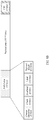
- a structure of the code block is shown in FIG. 5 .
- the quantity of bits occupied by the code block is not specifically limited in this embodiment of this application, and it only needs to be ensured that the quantity of bits occupied by the code block is less than or equal to half of a quantity of bits occupied by a payload area included in the data frame.
- the code block may include a payload area and an overhead area.
- the overhead area may also be referred to as a label area, or may be named another name. This is not specifically limited in this embodiment of this application.
- the payload area is used to carry service data, and the overhead area is used to carry overhead information required to transmit the service data.
- the code block may further include a check area, and the check area is used to indicate correctness of the service data carried in the payload area of the code block and correctness of the information included in the overhead area.
- a cyclic redundancy check cyclic redundancy check (cyclic redundancy check, CRC) mode is used.
- the overhead area of the code block includes a channel identifier field, and the channel identifier field is used to carry identification information that identifies the service data.
- the identification information in this embodiment of this application may also be referred to as a label.
- the identification information is a value used to indicate a port from which the service data comes.
- the identification information may be port information of the port from which the service data comes and/or routing information of the service data, or other information used to identify the service data is applicable to this embodiment of this application.
- the overhead area may further include at least one of the following: a check field and an overhead field.
- the check field is used to check correctness of the code block, for example, correctness of the service data carried by the code block, or correctness of one or several fields.
- the overhead field is mainly used to manage and monitor the service data in the payload area.
- the overhead field may include at least one of a large multiframe indication, a small multiframe indication, a service type indication, a backward defect indication, a forward defect indication, an automatic protection switching overhead, and a trail trace byte.
- each item in the overhead field may occupy only one bit.
- a quantity of bits occupied by each item of the overhead field may be increased depending on a requirement.
- the large multiframe indication is represented by MR in FIG. 6 , where the large multiframe indication is used to indicate a period of one large multiframe, the large multiframe includes M consecutive code blocks, and M is a positive integer.
- the small multiframe indication is represented by mr in FIG. 6 , where the large multiframe indication is used to indicate a period of one small multiframe, the small multiframe includes N consecutive code blocks, and N is a positive integer less than M.
- the service type indication is represented by PT in FIG. 6 , where the service type indication is used to indicate a mapping mode used for mapping the service data to the code block.
- the backward defect indication is used to indicate that a detected signal fail status is transmitted in an upstream direction, and the backward defect indication is represented by a BDI in FIG. 6 .
- the forward defect indication is used to indicate that a detected signal fail status is transmitted in a downstream direction, and the forward defect indication is represented by an FDI in FIG. 6 .
- the automatic protection switching overhead is used to carry transmission protection switching protocol information, and is represented by APS in FIG. 6 .
- APS transmission protection switching protocol information
- 32 bits are required to transmit APS. Therefore, when each code block has only one bit used to transmit the APS, a small multiframe period of 32 code blocks may be configured, so that the APS may be transmitted by using the small multiframe period.
- the trail trace byte is used to carry a trail trace identifier, and the trail trace identifier is represented by a TTI in FIG. 6 .
- TTI time to transmit
- 64 bytes 512 bits
- 64 bytes 512 bits
- a large multiframe period of 512 code blocks may be configured, so that the TTI may be transmitted by using the large multiframe period.
- the large multiframe period and the small multiframe period are used to indicate fields that use different multiframe periods. In practical use, a single multiframe period or a plurality of multiframe periods may be used depending on a specific requirement. This is not limited in the present invention.
- the overhead field may further include a reserved (RES) byte, and is configured depending on a future requirement.
- RES reserved
- the payload area included in the code block may carry data of a packet-type service, for example, an Ethernet service and an enhanced common public radio interface (enhanced common public radio interface, eCPRI) service.
- the payload area included in the code block may carry data of a constant bit rate (constant bit rate, CBR) service, for example, a plesiochronous digital service (plesiochronous digital hierarchy, PDH), a synchronous digital hierarchy (synchronous digital hierarchy, SDH), an Ethernet service, a CPRI service, an eCPRI service, a fiber channel (fiber channel, FC) service, and a passive optical network (passive optical network, PON).
- CBR constant bit rate
- a code block when a code block is configured for a data frame, if a quantity of bits occupied by a payload area of one data frame is not enough to be divided exactly by a quantity of bits occupied by the code block, a quantity of remaining bits obtained after exact division may be inserted into fixed padding, and places of the fixed padding are not used to transmit service data.
- a code block occupies K bits
- a payload area included in one data frame occupies L bits
- L%K S1, where both K and L are positive integers, and S1 is an integer greater than 0.
- S1 bits in the data frame are used for fixed padding.
- the code block may be configured for the several data frames as a whole.
- a code block occupies K bits
- a payload area of one data frame occupies L bits
- P ⁇ L/K W, where both K and L are integers greater than 0, P is an integer greater than or equal to 1, and W is an integer greater than 0. That is, W code blocks are exactly configured for P FlexO frames.
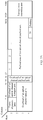
- a payload area (namely, an OPU) of the first OTN frame occupies 3808 ⁇ 4 bytes.
- a multiframe structure of four frames is defined.
- the multiframe structure is exactly divided into 317 code blocks that occupy 192 bytes without additional fixed padding.
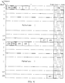
- the 82080 bytes are divided into code blocks of 192 bytes and can be divided into 427 code blocks of 192 bytes in the FlexO-SR frame, and remaining 96 bytes are used for fixed padding and used for padding of invalid data.
- carrying efficiency is relatively low, and there is a waste of 96 bytes of invalid bandwidth.
- a multiframe structure of two frames is defined by using an MFAS defined in the current G.709.1 standard protocol.
- MFAS defined in the current G.709.1 standard protocol.
- the multiframe FlexO structure is exactly divided into 855 code blocks that occupy 192 bytes without additional fixed padding.
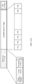
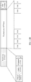
- the following structure may be defined for the code block that occupies 192 bytes. Refer to FIG. 8A and FIG. 8B for details.
- FIG. 8A shows an example of a code block structure for a packet-type service.
- the structure includes a payload area, an overhead area, and a check area. It should be noted that a quantity of bits occupied by each area of the code block mentioned in any embodiment of this application may be configured depending on a requirement. This is not specifically limited in this application.
- the overhead area includes a channel identifier field.
- the overhead area may further include at least one of the following: a check field, an overhead field, and an indication (indication, IND) field.
- the indication field is used to indicate whether the payload area included in the code block carries service data.
- a quantity of bits occupied by each field of the code block mentioned in any embodiment of this application may be configured depending on a requirement.
- the channel identifier field occupies two bytes (16 bits), the check field occupies one byte (8 bits), and the overhead field occupies one byte (8 bits), the indication field occupies one bit, the payload area occupies 23 x 65 bits, and the check area occupies one byte (8 bits).
- the indication field for example, when no actual packet-type service data is to be sent in the payload area of the code block, an IND may be set to "0", and fixed label data such as "0xFF" is added to the payload area of the code block.
- the IND When packet-type service data is mapped to the payload area of the code block, the IND may be set to "1". Certainly, another identification manner is used to indicate whether there is actual service data to be sent in the payload area of the code block. This is not specifically limited in this application.
- FIG. 8B shows an example of a code block structure for a CBR service.
- the structure is different from the code block structure for the packet-type service in that:
- An overhead area of a code block does not include an indication field, but may include a payload length field and/or a timestamp field.
- the timestamp field may occupy 32 bits, and the payload length field may occupy 16 bits, so that a payload area for the CBR service occupies 181 bytes (181 x 8 bits).
- the timestamp field is used to indicate a time at which service data is mapped to the code block, and the payload length field is used to indicate a length of the service data carried by the code block.
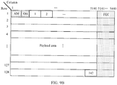
- FIG. 9A the example in which the code block that occupies 240 bytes is configured for the OTN frame shown in FIG. 3 is used.
- a payload area (namely, an OPU) of the OTN frame occupies 3808 ⁇ 4 bytes.
- the 82080 bytes are divided into code blocks of 240 bytes, and one FlexO-SR frame can be exactly divided into 342 code blocks that occupy 240 bytes without additional fixed padding.
- a structure of the code block that occupies 240 bytes (1920 bits) may be configured in a configuration manner similar to the structure of the code block that occupies 192 bytes.
- configuration manners for an overhead area and a check area of the code block of 240 bytes may be the same as configuration manners for an overhead area and a check area of the code block of 192 bytes, and a quantity of bits occupied by a payload area of the code block of 240 bytes is 1879 bits.
- the payload area of the code block of 240 bytes occupies 229 bytes.
- TDM time division multiplexing
- the embodiments of this application provide a method and an apparatus for processing service data in an optical transport network.
- a code block of a smaller granularity is defined in a data frame, and a channel identifier field is defined in an overhead area of the code block, to provide identification information that carries service data carried in a payload area. Then, before service data is mapped to the data frame, a quantity of code blocks in each data frame that are used to carry the service data and locations of the code blocks are determined depending on a requirement, and then the service data is mapped to the data frame based on the quantity and the locations.
- code blocks at a same location in a plurality of consecutive data frames may be occupied by service data from different ports, so that flexible configuration of the data frame may be implemented, and data frame transmission flexibility is further improved.
- the method and the apparatus are based on a same inventive concept. Because principles for resolving a problem of the method and the apparatus are similar, mutual reference may be made to implementations of the apparatus and the method, and repeated descriptions are not described.
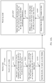
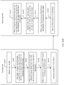
- FIG. 10A and FIG. 10B each are a flowchart of a method for processing service data in an optical transport network according to an embodiment of this application.
- the processing method may be applied to the OTN device shown in FIG. 1 .
- the method may be implemented by the tributary board in the OTN device shown in FIG. 2 .
- the method may be executed by a processing module disposed in the OTN device, or may be executed by a processing chip.
- the processing method includes the following steps.
- a sending node (namely, an OTN device on a transmitter side) receives service data, where the service data is to be mapped to a plurality of consecutive data frames.
- Each data frame includes a fixed quantity of code blocks.
- the sending node determines a quantity of code blocks, occupied by the service data, of each of the plurality of consecutive data frames and locations of the code blocks.
- the code block includes a payload area and an overhead area, the payload area of the code block is used to carry the service data, and the overhead area of the code block is used to carry identification information that identifies the service data.
- the sending node may determine, based on bandwidth of the service data, the quantity of code blocks occupied by the service data and specific locations of these code blocks in a data frame. It should be noted that the sending node may determine a quantity of code blocks, occupied by service data, in a plurality of data frames and locations of the code blocks for one time. Alternatively, the sending node may determine a quantity of code blocks required when one data frame carries service data and required locations of the code blocks for one time. This is not limited in this application.
- S1003 The sending node maps, based on the quantity of code blocks and the locations of the code blocks, the service data to the plurality of consecutive data frames.
- the sending node maps the service data to the plurality of consecutive data frames based on the quantity of code blocks and the locations of the code blocks may be implemented in the following manner.
- the sending node maps the service data to a payload area of each code block corresponding to a location of the code block, and adds identification information used to identify the service data to a channel identifier field of the code block to which the service data is mapped. If an overhead area of the code block further includes an overhead field, the sending node adds management and monitoring information of the service data in the payload area to the overhead field. If the overhead area of the code block further includes a check field, the sending node adds check information used to check integrity of the code block to the check field.
- Code block manner used in the embodiments of this application is essentially different from a conventional timeslot manner.
- the conventional timeslot belongs to a TDM mechanism.
- a timeslot can be occupied by only a port to which the timeslot is allocated, and does not change in consecutive data frames unless timeslot configuration is changed.
- code blocks (for example, code blocks whose identifiers are "427" in FIG. 7B ) at a same location in a plurality of consecutive data frames may be occupied by service data from different ports.
- a channel identifier field of a label area of the code block is used to determine a port whose service data occupies a location of each code block in each data frame.
- the channel identifier field may be dynamically updated in each data frame.
- a data frame is divided into a plurality of code blocks, and a code block structure is defined.
- a corresponding channel identifier field is defined in the code block.
- code blocks at a location in a plurality of consecutive data frames or code blocks at several locations in a plurality of consecutive data frames may also be bundled, and are occupied by service data from a same port.
- the sending node may determine a quantity of code blocks, occupied by the service data, in one data frame and locations of the code blocks; and then, map the service data to the data frame based on the determined quantity of code blocks and the determined locations of the code blocks.
- a sending device may determine a quantity of code blocks, occupied by one piece of service data, in several consecutive data frames and locations of the code blocks for one time; and subsequently, map the service data the several consecutive data frames based on the quantity and the location information.
- the service data in this embodiment of this application generally refers to any type of service data.
- a type of service data is described.
- the sending node may determine data of code blocks, occupied by service data corresponding to each port, in one or more data frames and locations of the code blocks; and then, map the service data from the plurality of ports to the data frame.
- a rate of the code block in this embodiment of this application may be less than or equal to 1 Gbps.
- the rate of the code block may be set to 2 Mbps.
- the rate of the code block may be set to 155 Mbps.
- the rate of the code block may be set to 100 Mbps.
- the rate of the code block rate may be set to 622 Mbps or the like.
- the code block includes an overhead area in addition to a payload area that carries service data. Therefore, the rate of the code block is a rate of the payload area.
- An actual overall rate of the code block is slightly higher than a rate of service data that matches the code block.
- each code block of the Ethernet code stream is 65B.
- the code block of 192 bytes shown in FIG. 8A is used as an example.
- a quantity of bits occupied by the payload area included in the code block of 192 bytes is 1445 bits, and one code block of 192 bytes can carry 23 code blocks of 65B.
- every 23 code blocks in the Ethernet code stream may be mapped to a payload area included in one code block of 192 bytes, as shown in FIG. 11A .
- One data frame may include one OTN frame (for example, the first OTN frame shown in FIG. 3 or the FlexO frame shown in FIG. 4 ) or a plurality of OTN frames.
- one data frame includes one OTN frame: If a quantity of bits occupied by one OTN frame is not enough to be divided exactly by a quantity of bits occupied by a code block, fixed padding may be configured in the OTN frame.
- a code block occupies K bits
- a payload area included in one OTN frame occupies L bits
- L%K S1
- S1 is an integer greater than 0.
- one data frame may include a plurality of consecutive OTN frames: If a quantity of bits occupied by a payload area of one OTN frame is not enough to be divided exactly by a quantity of bits occupied by a code block, the plurality of consecutive OTN frames (one OTN multiframe) may form one data frame, so that a quantity of bits occupied by a payload area of one OTN multiframe can be divided exactly by a quantity of bits occupied by a code block.
- each code block occupies K bits
- the payload area included in the OTN frame occupies L bits
- P ⁇ L/K W, where both K and L are integers greater than 0, P is an integer greater than or equal to 1, and W is an integer greater than 0.
- step S1002 the sending node determines a quantity of code blocks occupied by the service data, of each of the plurality of consecutive data frames and the locations of the code blocks may be implemented in the following manner:
- the quantity of code blocks used to carry the service data and the locations of the code blocks are determined in the W code blocks included in the P OTN frames, and then the service data may be mapped to the P OTN frames based on the determined quantity of code blocks and the determined locations of the code blocks.
- the sending node After mapping the service data to the plurality of consecutive data frames, the sending node performs S1004.
- the sending node sends the plurality of consecutive data frames.
- a receiving node (namely, an OTN device on a receiver side) receives the plurality of consecutive data frames.
- the data frame includes a fixed quantity of code blocks, an overhead area of each code block includes a channel identifier field, and the channel identifier field includes identification information used to identify the service data.
- the identification information carried by the channel identifier field may be port information that identifies a service data port and routing information.
- the OTN device may determine, based on the port information and the routing information, a port from which the service data carried by the code block comes.
- the receiving node identifies first code blocks, carrying same identification information, in each of the plurality of consecutive data frames.
- the receiving node obtains, from the first code blocks that carry the same identification information, service data identified by the same identification information.
- the sending node After mapping the service data to the plurality of consecutive data frames, the sending node performs S1008.
- the sending node maps the plurality of consecutive data frames to at least one FlexO frame.
- the sending node sends the at least one FlexO frame.
- a receiving node receives the at least one FlexO frame.
- the receiving node obtains, from the at least one FlexO frame, the plurality of consecutive data frames.
- Each data frame includes a fixed quantity of code blocks, each code block includes a payload area and an overhead area, the payload area is used to carry service data, and the overhead area includes identification information used to identify the service data.
- S1012 The receiving node identifies code blocks, carrying same identification information, in each of the plurality of consecutive data frames.
- the receiving node obtains, from the code blocks that carry the same identification information, service data identified by the same identification information.
- the receiving node determines, based on a channel identifier field of an overhead area of the code block, code blocks with same identification information included in the channel identifier field, determines integrity of the code block by using a check field, determines a service mapping mode by using a PT in an overhead field, and restores, according to the service mapping mode, service data from the code blocks with the same identification information.
- the channel identifier field may be pre-configured or configured dynamically.
- a data table may be pre-configured between the sending node and the receiving node, and the data table includes a correspondence between a label and a port number.
- the sending node determines, according to the configured data table, a label corresponding to a port number of a port from which to-be-sent service data comes, and adds the label to a channel identifier field of a code block occupied by the service data.
- the port number may alternatively be directly used to configure a forwarding data table.
- the FlexO frame may also pass through an intermediate node.
- a data table is also configured on the intermediate node.
- the data table on the intermediate node may include a correspondence between an ingress label corresponding to a source port and an egress label corresponding to a destination port.
- the intermediate node updates, according to the configured data table, a label included in a channel identifier field of each code block in the FlexO frame.
- the receiving node After receiving the FlexO frame sent by the sending node or the intermediate node, the receiving node can determine, by using the configured data table, code blocks in the FlexO frame that carry service data from a same port.
- an embodiment of this application further provides an apparatus for processing service data in an optical transport network.
- the apparatus is applied to a sending node, namely, an OTN device on a transmitter side.
- the apparatus may be specifically a processor, a chip, a chip system, a functional module used for sending, or the like, in the OTN device.
- the apparatus may include a receiving unit 1201, a determining unit 1202, a mapping unit 1203, and a sending unit 1204.
- the receiving unit 1201 is configured to perform S1001, the determining unit 1202 is configured to perform S1002, the mapping unit 1203 is configured to perform S1003 or is configured to perform S1003 and S1008, and the sending unit 1204 is configured to perform S1004 or S1009. Repeated descriptions not described herein.
- an embodiment of this application further provides another apparatus for processing service data in an optical transport network.
- the apparatus is applied to a receiving node, namely, an OTN device on a receiver side.
- the apparatus may be specifically a processor, a chip, a chip system, a functional module used for receiving, or the like, in the OTN device.
- the apparatus may include a receiving unit 1301, an identification unit 1302, and an obtaining unit 1303.
- the receiving unit 1301 is configured to perform S1005 or S1010
- the identification unit 1302 is configured to perform S1006 or configured to perform S1011 and S1012
- the obtaining unit 1303 is configured to perform S1007 or S1013. Repeated descriptions not described herein.
- unit division is exemplary, and is merely a logical function division. In actual implementation, another division manner may be used.
- functional units in the embodiments of this application may be integrated into one processor, or each of the units may exist alone physically, or two or more units are integrated into one unit.
- the integrated unit may be implemented in a form of hardware, or may be implemented in a form of a software functional unit.
- an embodiment of this application further provides another structure of an OTN device.
- an OTN device 1400 may include a communications interface 1410, a processor 1420, and a memory 1430.
- the OTN device may be applied to a sending node, or may be applied to a receiving node.
- the receiving unit 1201, the determining unit 1202, the mapping unit 1203, and the sending unit 1204 that are shown in FIG. 12 may all be implemented by the processor 1420.
- the processor 1420 receives service data through the communications interface 1410, and is configured to implement the method performed by the sending node in FIG. 10A and FIG. 10B .
- the method performed by the sending node in FIG. 10A and FIG. 10B may be completed by using an integrated logic circuit of hardware in the processor 1420 or an instruction in a form of software.
- the receiving unit 1301, the identification unit 1302, and the obtaining unit 1303 that are shown in FIG. 13 may be implemented by the processor 1420.
- the processor 1420 receives service data through the communications interface 1410, and is configured to implement the method performed by the receiving node in FIG. 10A and FIG. 10B .
- the method performed by the receiving node in FIG. 10A and FIG. 10B may be completed by using an integrated logic circuit of hardware in the processor 1420 or an instruction in a form of software.
- the communications interface 1410 in this embodiment of this application may be a circuit, a bus, a transceiver, or any other apparatus that can be configured to exchange information.
- the another apparatus may be a device connected to the OTN device 1400.
- the another apparatus may be a receiving node or an intermediate node.
- the processor 1420 may be a general-purpose processor, a digital signal processor, an application-specific integrated circuit, a field programmable gate array or another programmable logic device, a discrete gate or transistor logic device, or a discrete hardware component, and may implement or execute the methods, steps, and logical block diagrams disclosed in the embodiments of this application.
- the general-purpose processor may be a microprocessor, any conventional processor, or the like.
- the steps of the method disclosed with reference to the embodiments of this application may be directly performed by a hardware processor, or may be performed by using a combination of hardware in the processor and a software unit.
- Program code executed by the processor 1420 for implementing the foregoing method may be stored in the memory 1430.
- the memory 1430 is coupled to the processor 1420. Couplings in the embodiments of this application are indirect couplings or communication connections between apparatuses, units, or modules, may be electrical, mechanical, or another form, and are used for information interaction between the apparatuses, the units, and the modules.
- the processor 1420 may operate with the memory 1430 together.
- the memory 1430 may be a nonvolatile memory, for example, a hard disk drive (hard disk drive, HDD) or a solid-state drive (solid-state drive, SSD), or may be a volatile memory (volatile memory), for example, a random-access memory (random-access memory, RAM).
- the memory 1430 is any other medium that can be used to carry or store expected program code that has an instruction or a data structure form, and that can be accessed by a computer, but is not limited thereto.
- This embodiment of this application does not limit a specific connection medium between the communications interface 1410, the processor 1420, and the memory 1430.
- the memory 1430, the processor 1420, and the communications interface 1410 are connected by using a bus.
- the bus is represented by a thick line in FIG. 14 , and a connection manner between other parts is merely an example for description, and imposes no limitation.
- the bus may be classified into an address bus, a data bus, a control bus, and the like. For ease of representation, only one thick line is used to represent the bus in FIG. 14 , but this does not mean that there is only one bus or only one type of bus.
- an embodiment of this application further provides a computer storage medium.
- the storage medium stores a software program, and when the software program is read and executed by one or more processors, the method provided by any one or more of the foregoing embodiments may be implemented.
- the computer storage medium may include any medium that can store program code, such as a USB flash drive, a removable hard disk, a read-only memory, a random-access memory, a magnetic disk, or an optical disc.
- an embodiment of this application further provides a chip.
- the chip includes a processor configured to implement a function mentioned in any one or more of the foregoing embodiments, for example, obtain or process the data frame mentioned in the foregoing method.
- the chip further includes a memory, and the memory is configured to execute a necessary program instruction and data.
- the chip may include a chip, or may include a chip and another discrete device.
- this application may be provided as a method, a system, or a computer program product. Therefore, this application may use a form of hardware-only embodiments, software-only embodiments, or embodiments with a combination of software and hardware. Moreover, this application may use a form of a computer program product that is implemented on one or more computer-usable storage media (including but not limited to a disk memory, a CD-ROM, an optical memory, and the like) that include computer usable program code.
- a computer-usable storage media including but not limited to a disk memory, a CD-ROM, an optical memory, and the like
- These computer program instructions may be provided for a general-purpose computer, a dedicated computer, an embedded processor, or a processor of any other programmable data processing device to generate a machine, so that the instructions executed by a computer or a processor of any other programmable data processing device generate an apparatus for implementing a specified function in one or more processes in the flowcharts and/or in one or more blocks in the block diagrams.
- These computer program instructions may be stored in a computer-readable memory that can instruct the computer or any other programmable data processing device to work in a specific manner, so that the instructions stored in the computer-readable memory generate an artifact that includes an instruction apparatus.
- the instruction apparatus implements a specific function in one or more processes in the flowcharts and/or in one or more blocks in the block diagrams.
- These computer program instructions may alternatively be loaded onto a computer or any other programmable data processing device, so that a series of operations and steps are performed on the computer or the any other programmable device, thereby generating computer-implemented processing. Therefore, the instructions executed on the computer or the any other programmable device provide steps for implementing a specified function in one or more processes in the flowcharts and/or in one or more blocks in the block diagrams.
Landscapes
- Engineering & Computer Science (AREA)
- Computer Networks & Wireless Communication (AREA)
- Signal Processing (AREA)
- Quality & Reliability (AREA)
- Physics & Mathematics (AREA)
- Electromagnetism (AREA)
- Time-Division Multiplex Systems (AREA)
Applications Claiming Priority (1)
| Application Number | Priority Date | Filing Date | Title |
|---|---|---|---|
| PCT/CN2018/076014 WO2019153253A1 (zh) | 2018-02-09 | 2018-02-09 | 一种光传送网中业务数据的处理方法及装置 |
Publications (2)
| Publication Number | Publication Date |
|---|---|
| EP3737110A1 true EP3737110A1 (de) | 2020-11-11 |
| EP3737110A4 EP3737110A4 (de) | 2021-01-13 |
Family
ID=67549193
Family Applications (1)
| Application Number | Title | Priority Date | Filing Date |
|---|---|---|---|
| EP18904680.8A Pending EP3737110A4 (de) | 2018-02-09 | 2018-02-09 | Verfahren und vorrichtung zur verarbeitung von dienstdaten in einem optischen transportnetz |
Country Status (4)
| Country | Link |
|---|---|
| US (1) | US11700083B2 (de) |
| EP (1) | EP3737110A4 (de) |
| CN (2) | CN114844593A (de) |
| WO (1) | WO2019153253A1 (de) |
Cited By (1)
| Publication number | Priority date | Publication date | Assignee | Title |
|---|---|---|---|---|
| EP4135338A4 (de) * | 2020-04-27 | 2023-10-11 | Huawei Technologies Co., Ltd. | Dienstverarbeitungsverfahren, -vorrichtung und -vorrichtung |
Families Citing this family (24)
| Publication number | Priority date | Publication date | Assignee | Title |
|---|---|---|---|---|
| CN112511915A (zh) * | 2020-02-28 | 2021-03-16 | 中兴通讯股份有限公司 | 光传送网中业务处理方法、处理装置和电子设备 |
| CN112511916A (zh) * | 2020-02-28 | 2021-03-16 | 中兴通讯股份有限公司 | 光传送网中业务处理方法、处理装置和电子设备 |
| CN113573174A (zh) | 2020-04-28 | 2021-10-29 | 华为技术有限公司 | 业务处理的方法和装置 |
| CN113972997B (zh) | 2020-07-25 | 2025-09-12 | 华为技术有限公司 | 一种传输数据的方法和设备 |
| CN114374469A (zh) * | 2020-10-15 | 2022-04-19 | 华为技术有限公司 | 通信方法、装置及系统 |
| CN114727175B (zh) * | 2021-01-05 | 2025-09-05 | 中国移动通信有限公司研究院 | 数据传输方法及设备 |
| CN114727177B (zh) * | 2021-01-05 | 2024-12-10 | 烽火通信科技股份有限公司 | 一种mtn oam序列同步方法和装置 |
| CN112929355A (zh) * | 2021-01-29 | 2021-06-08 | 中兴通讯股份有限公司 | 一种光传送网的安全管理信息处理方法及装置 |
| CN114866175B (zh) * | 2021-02-03 | 2024-07-05 | 华为技术有限公司 | 通信方法及设备 |
| US11569924B2 (en) | 2021-04-26 | 2023-01-31 | Cisco Technology, Inc. | Access point identifiers in 400ZR and 400ZR+ protocols |
| CN114157383B (zh) * | 2021-12-03 | 2023-04-28 | 安徽皖通邮电股份有限公司 | 基于FPGA的Cm时钟恢复算法、系统、存储介质及设备 |
| CN116488768A (zh) * | 2022-01-14 | 2023-07-25 | 华为技术有限公司 | 开销信息传输方法、通信装置和系统 |
| CN116582219B (zh) * | 2022-01-30 | 2026-01-06 | 华为技术有限公司 | 一种光传送网中的数据帧的处理方法、装置和系统 |
| WO2023221966A1 (zh) * | 2022-05-20 | 2023-11-23 | 华为技术有限公司 | 一种传输数据的方法和装置 |
| CN117201968A (zh) * | 2022-05-30 | 2023-12-08 | 华为技术有限公司 | 业务数据处理的方法和装置 |
| CN117354647A (zh) * | 2022-06-29 | 2024-01-05 | 华为技术有限公司 | 数据帧的校验方法及相关设备 |
| WO2024040604A1 (zh) * | 2022-08-26 | 2024-02-29 | 华为技术有限公司 | 一种数据传输方法及装置 |
| CN117692822A (zh) * | 2022-09-05 | 2024-03-12 | 华为技术有限公司 | 一种光传送网中的数据帧的处理方法、装置和系统 |
| US12334978B2 (en) * | 2022-10-13 | 2025-06-17 | Qualcomm Incorporated | Feedback mechanism for a laser based optical wireless communications system |
| CN118175208A (zh) * | 2022-12-09 | 2024-06-11 | 中国移动通信有限公司研究院 | 固定带宽业务的承载方法、装置、电子设备及存储介质 |
| CN118264939A (zh) * | 2022-12-26 | 2024-06-28 | 华为技术有限公司 | 一种传输帧的映射和解映射方法以及相关设备 |
| CN118740325A (zh) * | 2023-03-31 | 2024-10-01 | 中国移动通信有限公司研究院 | 传输方法、装置、计算机可读存储介质和通信设备 |
| CN119544079B (zh) * | 2025-01-16 | 2025-04-15 | 芯潮流(珠海)科技有限公司 | 光通信业务数据的承载方法、承载设备和收发设备 |
| CN119561656B (zh) * | 2025-02-06 | 2025-07-22 | 芯潮流(珠海)科技有限公司 | 面向高速互联的多业务混合承载方法、承载设备和混合业务发送设备 |
Family Cites Families (28)
| Publication number | Priority date | Publication date | Assignee | Title |
|---|---|---|---|---|
| CN100590997C (zh) * | 2004-11-02 | 2010-02-17 | 华为技术有限公司 | 一种otn网络中业务复用的开销处理方法 |
| CN101291179B (zh) * | 2007-04-17 | 2011-03-23 | 华为技术有限公司 | 一种光传送网中客户信号传送方法及相关设备 |
| CN101335751A (zh) * | 2007-06-29 | 2008-12-31 | 华为技术有限公司 | 将以太网编码块映射到光传输网络传输的方法及装置 |
| CN101345700B (zh) * | 2007-07-10 | 2011-12-07 | 华为技术有限公司 | 将以太网编码块映射到光传输网络传输的方法及装置 |
| CN101499997B (zh) * | 2008-01-29 | 2013-06-05 | 中兴通讯股份有限公司 | 一种多路低速业务复用及解复用装置及其方法 |
| CN101615967B (zh) * | 2008-06-26 | 2011-04-20 | 华为技术有限公司 | 一种业务数据的发送、接收方法、装置和系统 |
| CN101378399B (zh) * | 2008-09-28 | 2012-04-04 | 华为技术有限公司 | 业务数据映射和解映射方法及装置 |
| CN101800912B (zh) * | 2009-02-10 | 2016-08-10 | 华为技术有限公司 | 客户信号映射和解映射的实现方法及装置 |
| CN101834688B (zh) * | 2009-03-09 | 2011-08-31 | 华为技术有限公司 | 光传送网中的映射、解映射方法及装置 |
| JP5251620B2 (ja) * | 2009-03-09 | 2013-07-31 | 富士通株式会社 | フレーム生成装置およびフレーム生成方法 |
| CN101841741B (zh) * | 2009-03-16 | 2015-04-08 | 华为技术有限公司 | 光通道传送单元信号的传输方法和装置 |
| CN101651512B (zh) * | 2009-09-24 | 2013-06-05 | 中兴通讯股份有限公司 | 一种实现数据业务透明传送的方法、系统及装置 |
| CN103825668B (zh) * | 2009-12-24 | 2017-06-16 | 华为技术有限公司 | 通用映射规程gmp映射方法、解映射方法及装置 |
| EP2680469B1 (de) * | 2009-12-24 | 2016-03-23 | Huawei Technologies Co., Ltd. | Verfahren und Vorrichtung für GMP-Mapping und -Demapping |
| CN102594648B (zh) * | 2011-01-07 | 2014-11-05 | 中兴通讯股份有限公司 | 业务调度方法及装置 |
| US8644340B2 (en) * | 2011-02-07 | 2014-02-04 | Cisco Technology, Inc. | Multiplexing in an optical transport network (OTN) |
| EP2621118A4 (de) * | 2011-11-15 | 2013-07-31 | Huawei Tech Co Ltd | Verfahren, vorrichtung und system zur übertragung von servicedaten in einem optischen transportnetzwerk |
| EP2843966A4 (de) * | 2012-04-26 | 2015-04-29 | Zte Corp | Gmp-abbildungsverfahren und -vorrichtung für eine dateneinheit in einem optischen kanal |
| CN102820951B (zh) * | 2012-07-30 | 2016-12-21 | 华为技术有限公司 | 光传送网中传送、接收客户信号的方法和装置 |
| EP3065318B1 (de) * | 2015-03-06 | 2020-04-22 | Alcatel Lucent | Übertragungsverfahren |
| CN106301678B (zh) * | 2015-06-08 | 2020-02-14 | 华为技术有限公司 | 一种数据处理的方法、通信设备及通信系统 |
| CN106341352B (zh) * | 2015-07-15 | 2020-06-16 | 华为技术有限公司 | 用于光传送网的域间接口数据传送的方法和装置 |
| CN107040314A (zh) * | 2016-02-03 | 2017-08-11 | 中兴通讯股份有限公司 | 一种业务传送的方法及装置 |
| CN109478941B (zh) * | 2016-07-22 | 2020-06-26 | 华为技术有限公司 | 一种多路业务传送、接收方法及装置 |
| CN109981209B (zh) * | 2017-12-28 | 2022-01-28 | 中兴通讯股份有限公司 | 光传送网中业务发送、接收方法及装置 |
| CN110557217B (zh) * | 2018-06-01 | 2021-08-03 | 华为技术有限公司 | 一种业务数据的处理方法及装置 |
| CN110649986B (zh) * | 2018-06-26 | 2022-07-19 | 中兴通讯股份有限公司 | 使用灵活光网络的业务传输方法、装置、设备及存储介质 |
| GB2580867B (en) * | 2018-10-25 | 2021-12-29 | Cisco Tech Inc | Methods, apparatuses and system for error control |
-
2018
- 2018-02-09 WO PCT/CN2018/076014 patent/WO2019153253A1/zh not_active Ceased
- 2018-02-09 EP EP18904680.8A patent/EP3737110A4/de active Pending
- 2018-02-09 CN CN202210318320.6A patent/CN114844593A/zh active Pending
- 2018-02-09 CN CN201880088426.3A patent/CN111713117B/zh active Active
-
2020
- 2020-08-07 US US16/987,802 patent/US11700083B2/en active Active
Cited By (1)
| Publication number | Priority date | Publication date | Assignee | Title |
|---|---|---|---|---|
| EP4135338A4 (de) * | 2020-04-27 | 2023-10-11 | Huawei Technologies Co., Ltd. | Dienstverarbeitungsverfahren, -vorrichtung und -vorrichtung |
Also Published As
| Publication number | Publication date |
|---|---|
| CN114844593A (zh) | 2022-08-02 |
| US11700083B2 (en) | 2023-07-11 |
| CN111713117B (zh) | 2022-04-12 |
| CN111713117A (zh) | 2020-09-25 |
| WO2019153253A1 (zh) | 2019-08-15 |
| US20200366412A1 (en) | 2020-11-19 |
| EP3737110A4 (de) | 2021-01-13 |
Similar Documents
| Publication | Publication Date | Title |
|---|---|---|
| US11700083B2 (en) | Method and apparatus for processing service data in optical transport network | |
| US11234055B2 (en) | Service data processing method and apparatus | |
| US11082199B2 (en) | Data transmission method in optical network and optical network device | |
| US11764874B2 (en) | Method for processing low-rate service data in optical transport network, apparatus, and system | |
| CN111865887B (zh) | 光传送网中的数据传输方法及装置 | |
| EP4027650A1 (de) | Verfahren und vorrichtung zum verarbeiten von diensten in einem optischen transportnetz und system | |
| EP4099712A1 (de) | Dienstträgerverfahren, vorrichtung und system | |
| EP2472748B1 (de) | Verfahren und kommunikationsknoten zum einstellen der bandbreite | |
| US8958701B2 (en) | Methods and systems of preserving client overhead bytes in optical transport network tunneling applications | |
| US11750314B2 (en) | Service data processing method and apparatus | |
| US11223422B2 (en) | Method and apparatus for processing ethernet data in optical network, and system | |
| US20110318001A1 (en) | Method and device for sending and receiving service data | |
| CN111740782B (zh) | 一种业务数据的处理方法及装置 | |
| CN111989933B (zh) | 光传送网中的数据传输方法及装置 | |
| CN120167112A (zh) | 一种带宽调整方法及装置 | |
| EP1973250A1 (de) | Verfahren und Vorrichtung für den Transport von Client-Signalen über transparente Netzwerke mittels virtueller Verknüpfung | |
| CN120475285A (zh) | 一种数据处理方法及装置 | |
| CN120238779A (zh) | 一种客户信号映射、解映射的方法及相关设备 |
Legal Events
| Date | Code | Title | Description |
|---|---|---|---|
| STAA | Information on the status of an ep patent application or granted ep patent |
Free format text: STATUS: THE INTERNATIONAL PUBLICATION HAS BEEN MADE |
|
| PUAI | Public reference made under article 153(3) epc to a published international application that has entered the european phase |
Free format text: ORIGINAL CODE: 0009012 |
|
| STAA | Information on the status of an ep patent application or granted ep patent |
Free format text: STATUS: REQUEST FOR EXAMINATION WAS MADE |
|
| 17P | Request for examination filed |
Effective date: 20200807 |
|
| AK | Designated contracting states |
Kind code of ref document: A1 Designated state(s): AL AT BE BG CH CY CZ DE DK EE ES FI FR GB GR HR HU IE IS IT LI LT LU LV MC MK MT NL NO PL PT RO RS SE SI SK SM TR |
|
| AX | Request for extension of the european patent |
Extension state: BA ME |
|
| REG | Reference to a national code |
Ref country code: DE Ref legal event code: R079 Free format text: PREVIOUS MAIN CLASS: H04Q0011000000 Ipc: H04J0003160000 |
|
| A4 | Supplementary search report drawn up and despatched |
Effective date: 20201214 |
|
| RIC1 | Information provided on ipc code assigned before grant |
Ipc: H04J 3/16 20060101AFI20201208BHEP Ipc: H04J 3/06 20060101ALI20201208BHEP |
|
| DAV | Request for validation of the european patent (deleted) | ||
| DAX | Request for extension of the european patent (deleted) | ||
| STAA | Information on the status of an ep patent application or granted ep patent |
Free format text: STATUS: EXAMINATION IS IN PROGRESS |
|
| 17Q | First examination report despatched |
Effective date: 20230922 |