EP3737632B1 - Dispositif de levage - Google Patents
Dispositif de levage Download PDFInfo
- Publication number
- EP3737632B1 EP3737632B1 EP19700854.3A EP19700854A EP3737632B1 EP 3737632 B1 EP3737632 B1 EP 3737632B1 EP 19700854 A EP19700854 A EP 19700854A EP 3737632 B1 EP3737632 B1 EP 3737632B1
- Authority
- EP
- European Patent Office
- Prior art keywords
- working device
- crane arm
- sensor
- working
- lifting device
- Prior art date
- Legal status (The legal status is an assumption and is not a legal conclusion. Google has not performed a legal analysis and makes no representation as to the accuracy of the status listed.)
- Active
Links
Images


Classifications
-
- B—PERFORMING OPERATIONS; TRANSPORTING
- B66—HOISTING; LIFTING; HAULING
- B66F—HOISTING, LIFTING, HAULING OR PUSHING, NOT OTHERWISE PROVIDED FOR, e.g. DEVICES WHICH APPLY A LIFTING OR PUSHING FORCE DIRECTLY TO THE SURFACE OF A LOAD
- B66F11/00—Lifting devices specially adapted for particular uses not otherwise provided for
- B66F11/04—Lifting devices specially adapted for particular uses not otherwise provided for for movable platforms or cabins, e.g. on vehicles, permitting workmen to place themselves in any desired position for carrying out required operations
- B66F11/044—Working platforms suspended from booms
- B66F11/046—Working platforms suspended from booms of the telescoping type
-
- B—PERFORMING OPERATIONS; TRANSPORTING
- B66—HOISTING; LIFTING; HAULING
- B66C—CRANES; LOAD-ENGAGING ELEMENTS OR DEVICES FOR CRANES, CAPSTANS, WINCHES, OR TACKLES
- B66C23/00—Cranes comprising essentially a beam, boom, or triangular structure acting as a cantilever and mounted for translatory of swinging movements in vertical or horizontal planes or a combination of such movements, e.g. jib-cranes, derricks, tower cranes
- B66C23/54—Cranes comprising essentially a beam, boom, or triangular structure acting as a cantilever and mounted for translatory of swinging movements in vertical or horizontal planes or a combination of such movements, e.g. jib-cranes, derricks, tower cranes with pneumatic or hydraulic motors, e.g. for actuating jib-cranes on tractors
-
- B—PERFORMING OPERATIONS; TRANSPORTING
- B25—HAND TOOLS; PORTABLE POWER-DRIVEN TOOLS; MANIPULATORS
- B25J—MANIPULATORS; CHAMBERS PROVIDED WITH MANIPULATION DEVICES
- B25J13/00—Controls for manipulators
- B25J13/08—Controls for manipulators by means of sensing devices, e.g. viewing or touching devices
- B25J13/088—Controls for manipulators by means of sensing devices, e.g. viewing or touching devices with position, velocity or acceleration sensors
-
- B—PERFORMING OPERATIONS; TRANSPORTING
- B25—HAND TOOLS; PORTABLE POWER-DRIVEN TOOLS; MANIPULATORS
- B25J—MANIPULATORS; CHAMBERS PROVIDED WITH MANIPULATION DEVICES
- B25J19/00—Accessories fitted to manipulators, e.g. for monitoring, for viewing; Safety devices combined with or specially adapted for use in connection with manipulators
- B25J19/02—Sensing devices
- B25J19/021—Optical sensing devices
-
- B—PERFORMING OPERATIONS; TRANSPORTING
- B25—HAND TOOLS; PORTABLE POWER-DRIVEN TOOLS; MANIPULATORS
- B25J—MANIPULATORS; CHAMBERS PROVIDED WITH MANIPULATION DEVICES
- B25J5/00—Manipulators mounted on wheels or on carriages
- B25J5/007—Manipulators mounted on wheels or on carriages mounted on wheels
-
- B—PERFORMING OPERATIONS; TRANSPORTING
- B66—HOISTING; LIFTING; HAULING
- B66C—CRANES; LOAD-ENGAGING ELEMENTS OR DEVICES FOR CRANES, CAPSTANS, WINCHES, OR TACKLES
- B66C13/00—Other constructional features or details
- B66C13/18—Control systems or devices
-
- B—PERFORMING OPERATIONS; TRANSPORTING
- B66—HOISTING; LIFTING; HAULING
- B66C—CRANES; LOAD-ENGAGING ELEMENTS OR DEVICES FOR CRANES, CAPSTANS, WINCHES, OR TACKLES
- B66C23/00—Cranes comprising essentially a beam, boom, or triangular structure acting as a cantilever and mounted for translatory of swinging movements in vertical or horizontal planes or a combination of such movements, e.g. jib-cranes, derricks, tower cranes
- B66C23/62—Constructional features or details
- B66C23/64—Jibs
- B66C23/68—Jibs foldable or otherwise adjustable in configuration
-
- B—PERFORMING OPERATIONS; TRANSPORTING
- B66—HOISTING; LIFTING; HAULING
- B66F—HOISTING, LIFTING, HAULING OR PUSHING, NOT OTHERWISE PROVIDED FOR, e.g. DEVICES WHICH APPLY A LIFTING OR PUSHING FORCE DIRECTLY TO THE SURFACE OF A LOAD
- B66F17/00—Safety devices, e.g. for limiting or indicating lifting force
- B66F17/006—Safety devices, e.g. for limiting or indicating lifting force for working platforms
-
- B—PERFORMING OPERATIONS; TRANSPORTING
- B66—HOISTING; LIFTING; HAULING
- B66F—HOISTING, LIFTING, HAULING OR PUSHING, NOT OTHERWISE PROVIDED FOR, e.g. DEVICES WHICH APPLY A LIFTING OR PUSHING FORCE DIRECTLY TO THE SURFACE OF A LOAD
- B66F9/00—Devices for lifting or lowering bulky or heavy goods for loading or unloading purposes
- B66F9/06—Devices for lifting or lowering bulky or heavy goods for loading or unloading purposes movable, with their loads, on wheels or the like, e.g. fork-lift trucks
- B66F9/075—Constructional features or details
- B66F9/12—Platforms; Forks; Other load supporting or gripping members
- B66F9/18—Load gripping or retaining means
- B66F9/181—Load gripping or retaining means by suction means
Definitions
- the present invention relates to a lifting device according to the preamble of claim 1 and a vehicle with such a lifting device.
- a generic lifting device is from the EP 0 397 076 A1 known.
- This publication shows a forklift with a telescopic and vertically pivotable boom and a work device pivotably arranged on it.
- the pivoting position of the implement is synchronized with the movement of the lifting cylinder, which means that the horizontal alignment of the implement can be maintained when the boom arm is pivoted vertically.
- WO 2017/157482 A1 discloses a lifting device according to the preamble of claim 1.
- the object of the invention is to provide a crane which has expanded and easier operability as well as increased safety against incorrect operation.
- the lifting device therefore has an adjusting device by means of which the position of the working device can be adjusted relative to the crane arm.
- the position of the working device can correspond to a predetermined or predeterminable target position of the working device relative to the crane arm or a predetermined, predeterminable direction or orientation of the working device in space.
- At least one sensor is provided to detect the actual position of the working device, i.e. the current position of the working device relative to the crane arm or to a spatial direction during, for example, a work process.
- the signals from the sensor can be fed to the adjusting device.
- the adjusting device can move the implement into the desired position. This can occur if the actual position deviates from the desired position, whereby the working device can be moved from a substantially arbitrary position into the desired position, or, for example, the working device can be held in the desired position during a work process.
- the adjusting device has a drive for changing a geometry of the crane arm and the position of the working device can be changed by the drive for changing the geometry of the crane arm.
- the drive can be in the form of at least one hydraulic cylinder to change a Angle of inclination of the crane arm, a bending position of the crane arm or a pushing position of the crane arm.
- a swivel mechanism allows the crane arm to be swiveled about a vertical swivel axis, for example.
- the adjusting device can be used to move the crane arm, parts of the crane arm relative to one another and the working device relative to the crane arm or relative to parts of the crane arm.
- the adjusting device has an actuator arranged between the crane arm and the working device and the position of the working device can be changed by this actuator.
- an actuator i.e. a movement device
- the working device can be moved relative to the crane arm, for example, without changing the geometry of the crane arm.
- Such an actuator can be designed, for example, in the form of a rotator or rotary drive, a rack or a hydraulic cylinder. The actuator can be used to enable the implement to be pivoted, tilted, rotated or moved.
- An adjusting device which includes a crane arm whose geometry can be changed and an actuator arranged between the crane arm and the working device is also conceivable.
- the target position is designed as a position of the working device with at least one predetermined angle in space.
- a predetermined angle in space can, for example, correspond to an angle of an axis of the implement relative to the vertical or horizontal. In other words, one can speak of an absolute position of the working device in space.
- the at least one sensor can be used as an angle sensor, as a force or torque sensor, as an inclination sensor, as an acceleration sensor, as a proximity sensor, as an optical detection device or as a device for emitting and receiving sound waves, in particular ultrasound, or as a device for emitting and receiving of electromagnetic waves. in particular radar or laser light.
- This can - depending on the training of the... Sensor - the relative position of the working device to the crane arm and/or the position of the working device in relation to the direction in space can be recorded.
- a correspondingly designed sensor can also be used to determine or detect a deviation in the actual position of the working device relative to the target position of the working device.
- the adjusting device has a control to which the signals from the at least one sensor for detecting an actual position of the working device relative to the crane arm or to the direction in space can be fed.
- the control of the adjusting device can, for example, first convert the sensor signals (raw data) of a sensor supplied to it into a signal format that can be further processed by the control. In this way, the signals from the at least one sensor can be included in the movement of the implement by the adjusting device.
- control is arranged on the working device or is designed in a crane control of the crane arm.
- the control can therefore be designed separately from the crane control of the crane arm, for example as an additionally installed module, or as part of the crane control, for example integrated in the crane control.
- the crane control can include a stationary control station or a mobile radio console, whereby the control can also be designed in the control station or in the radio console.
- the control can basically have an operating mode in which the adjusting device moves the working device into the desired position depending on the signals from the at least one sensor supplied to the adjusting device if the actual position is not equal to the desired position.
- At least one sensor is provided, through which a change in the position of the working device relative to the crane arm or relative to the direction in space caused by picking up a load by means of the working device can be detected. Furthermore, at least one sensor can be provided, through which a mechanical load on the working device caused by picking up a load by means of the working device can be detected. Such a mechanical load on the working device can be, for example, a moment load.
- an attack of the implement on the load outside the center of gravity of the load can be detected.
- a movement of the working device that occurs when a load is picked up - for example, a pivoting, tilting, rotating or moving of the working device - can be detected.
- Such a movement can be caused by a moment acting on the working device, for example if, for example, an extended load is attacked or struck by the working device at a certain distance from the center of gravity of the load.
- the at least one sensor for detecting an actual position of the working device forms the at least one sensor.
- the sensor through which a change in the position of the implement relative to the crane arm or relative to the direction in space caused by picking up a load by means of the working device can be detected, or through which a mechanical load on the working device caused by picking up a load by means of the working device can be detected, can therefore be designed by the sensor to detect the actual position of the implement.
- the sensor for detecting the actual position of the working device can, for example, by detecting the current position of the working device relative to the crane arm or to a spatial direction during a work process, detect a change in the currently existing position, which results in a change in the position of the working device relative to the Crane arm or relative to the direction in space or a mechanical load on the working device can be dissipated.
- the adjusting device is designed to allow or support movements exerted manually or pedally by a user on the working device or on a load picked up by the working device or gesturally relative to the working device.
- an action by the user on the working device or on a load picked up by the working device can be converted into a movement of the working device by means of at least one of the installed sensors - if necessary in a particularly suitable operating mode of the adjusting device.
- the work device or a load picked up by the work device can be placed in a device stored by the user can be brought into a predetermined position by direct positioning (alignment). It is also conceivable that the working device can be positioned or aligned by the user using gesture control using one of the installed sensors.
- the working device is designed in the form of a load-carrying device.
- a load-carrying device in the form of a manipulator that generally enables physical interaction with the environment, a rotator, a tilt-rotator or a gripper.
- the load-carrying device can each include an actuator arranged on it.
- the at least one sensor for detecting an actual position of the working device can be arranged on or in the working device.
- the sensor can therefore be arranged on the working device or can be arranged in the working device or in a part of the working device.
- the sensor can also be arranged on the crane arm or can be arranged in the crane arm or in a part of the crane arm. It is also conceivable that the sensor can be arranged between the working device and the crane arm. It is not excluded that the sensor can be arranged on or in a vehicle.
- a particularly advantageous design of the lifting device can result if the lifting device is designed as a loading crane.
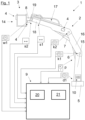
- FIG 1 an embodiment of a lifting device 1 in the form of a crane arm 2 with a working device 3 arranged thereon in the form of an aerial work platform 14 and a control 9 with associated sensors is shown.
- the crane arm 2 has a crane base 5, a crane column 15, a lifting arm 16 and an articulated arm 17, the articulated arm 17 having a telescopic first crane push arm 18 and a telescopic second crane push arm 19 for changing the length of the crane arm 2.
- the sensor system of the lifting device 1 includes a thrust position sensor s1 for detecting the thrust position of the first crane push arm 18, a thrust position sensor s1 for detecting the thrust position of the second crane push arm 19, a rotation angle sensor d1 for detecting the rotation position about a vertical axis of the crane column 15 to the crane base 5, an articulation angle sensor k1 for detecting the articulation angle position of the lifting arm 16 relative to the crane column 15, an articulation angle sensor k2 for detecting the articulation angle position of the articulation arm 17 relative to the lifting arm 16 and a pressure sensor p for detecting the hydraulic pressure in the hydraulic cylinder 6 (lifting cylinder) of the lifting device 1.
- a Pressure detection can also be done for the hydraulic cylinder 7 (articulated cylinder) of the lifting device 1.
- the sensor system in the embodiment shown includes a sensor 4, by means of which the position of the working device 3 or the aerial work platform 14 can be detected.
- the position of the working device 3 or the aerial work platform 14 detected by the sensor 4, which in this embodiment is designed as an angle sensor w1 can correspond to a position relative to the crane arm 2 or to a direction in space.
- the angle sensor w1 can be used to detect an angular position of the working device 3 or the aerial work platform 14 about one of the three spatial axes.
- a sensor 4 to detect the position of the working device 3 or the aerial work platform 14 to be arranged on the working device 3 or the aerial work platform 14 or on the crane arm 2 itself.
- the values recorded by the sensors are sent to the controller 9 via appropriate connections, be it a wired measuring line or a wireless connection.
- the controller 9 can have a memory 20 and a computing unit 21.
- the control 9 can be integrated in the crane control 10 of the crane arm 2 or can be arranged on the working device 3.
- the position of the working device 3 or the aerial work platform 14 can be changed by changing the geometry of the crane arm 2 and by an actuator 8 arranged between the crane arm 2 and the working device 3 or the aerial work platform 14.
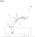
- Figure 2 shows a side view of a vehicle 13 with a lifting device 1 designed as a crane arm 2.
- the design of the lifting device 1 essentially corresponds to that of Figure 1 .
- Figure 3a shows a top view of a vehicle 13 with a lifting device 1 designed as a crane arm 2 with a crane arm 2 and a working device 3 in the form of a lifting work platform 14 which is arranged on the crane arm 2 and can be moved by this and an actuator 8.
- the design of the lifting device 1 corresponds again to Essentially that of Figure 1 .
- a sensor 4 it is possible for a sensor 4 to detect the position of the working device 3 or the aerial work platform 14 to be arranged on the working device 3, on the crane arm 2 and on the vehicle 13 itself.
- the working device 3 in the form of the aerial work platform is arranged to be adjustable relative to the crane arm 2, whereby in Figure 3a different pivot positions about a vertical pivot axis of the working device 3 in the form of an aerial work platform 14 are shown relative to the crane arm 2 during the pivoting of the crane arm 2 about the crane column 5.
- the detection of the relative position of the working device 3 or the aerial work platform 14 relative to the crane arm 2 or also the detection of the position of the working device 3 or the aerial work platform 14 in space can be arranged via a device 3 or the aerial work platform 14 or on the lifting device 1 Sensor 4 done.
- a target position of the working device 3 can correspond to a predetermined direction in space.
- the working device 3 in the form of the aerial work platform 14 can initially be aligned parallel to a wall 22 (left illustration of the crane arm 2 and the aerial work platform 14). This can happen when the crane arm 2 is pivoted about a vertical pivot axis
- Working device 3 in the form of the aerial work platform can be moved or pivoted by the adjusting device - which in this embodiment is formed by the crane arm 2 and the actuator 8 - in such a way that the working device 3 continues to be in the target position during the pivoting of the crane arm 2, i.e is held in the orientation parallel to the wall 22.
- the target position i.e. the specified spatial direction, can be an absolute direction in space or, as in Figure 3a shown, follow the direction of wall 22. An application for this is in Figure 3b shown.
- the representation of the Figure 3b essentially corresponds to that of Figure 3a , however, the wall 22 has an uneven course.
- the signals from the sensor 4 can be fed to the adjusting device, which is formed as shown by the crane arm 2 and the actuator 8, and the working device 3 in the form of the aerial work platform 14 can be held in the desired target position while the crane arm 2 is pivoted.
- the target position can correspond approximately to a constant distance of the working device 3 in the form of the aerial work platform 14 to the wall 22.
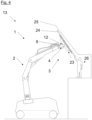
- FIG 4 shows a further embodiment of a vehicle 13 in the form of a crawler crane with a lifting device 1 in the form of a crane arm 2 with a working device 3 in the form of a vacuum suction gripper 23.
- Vacuum suction grippers 23 can be used, for example, when handling flat loads 11 such as a glass plate 24 be used.
- the lifting device 1 which is analogous to that in Figure 1 shown embodiment of the lifting device 1 can be equipped, again has a sensor 4 for detecting the current position of the working device 3 or the vacuum suction gripper 23.
- An actuator 8 is arranged between the crane arm 2 and the working device 3 or the vacuum suction gripper 23.
- the lifting device 1 has a further sensor 12, which can detect a mechanical load on the working device 3 caused by the load 11.
- the additional sensor 12 designed for example as a force sensor, can detect the weight or moment load exerted by the glass plate 24 on the vacuum suction cup 23 or the actuator 8. This makes it possible for a user 26 to access the work device 3 manually or pedal - i.e. by hand or foot or to allow or support movements exerted on a load 11 picked up by the implement 3.
- inserting the glass plate 24 on the facade 25 can be made easier by the user 26 directly, manually aligning the glass plate 24.
- the further sensor 12 is designed as an optical sensor and that the glass plate 24 and the working device 3 are indirectly aligned relative to the working device 3 by gestures of the user 26.
- FIG 5a and 5b Detailed views of a crane arm 2 with an actuator 8 arranged on it in the form of a tilt rotator are shown in various pivoting positions.
- the crane arm 2 can basically be analogous to that in Figure 1 shown version of the crane arm 2.
- a as in Figure 5a Actuator 8 shown can carry out or enable a pivoting movement about three spatial axes.
- a working device (not shown) arranged on the actuator 8 can be positioned essentially freely in space or relative to the crane arm 2.
- a as in Figure 5b Actuator 8 shown can allow a pivoting movement about two spatial axes.
- the in Figure 5a and 5b Actuator 8 shown can each have a sensor (not shown) through which the position of a working device arranged on the actuator 8 can be detected.
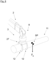
- FIG 6 is a detailed view of one like in the Figure 5a trained crane arm 2 with an actuator 8 arranged thereon and a working device 3 arranged thereon in the form of a gripper 27.
- the gripper 27 has sensors 12 designed as pressure sensors in the gripper tips, by means of which a force acting on the working device 3 by the load 11 picked up can be detected.
- a force acting on the actuator 8 can also be detected by a sensor (not shown) integrated in the actuator 8.
Landscapes
- Engineering & Computer Science (AREA)
- Mechanical Engineering (AREA)
- Structural Engineering (AREA)
- Life Sciences & Earth Sciences (AREA)
- Geology (AREA)
- Transportation (AREA)
- Robotics (AREA)
- Automation & Control Theory (AREA)
- Civil Engineering (AREA)
- Human Computer Interaction (AREA)
- Forklifts And Lifting Vehicles (AREA)
- Jib Cranes (AREA)
Claims (14)
- Dispositif de levage (1) avec un bras de grue (2) - de préférence articulé - et un appareil de travail (3) disposé sur le bras de grue (2) et pouvant être déplacé par celui-ci, dans lequel l'appareil de travail (3) est disposé de manière à pouvoir être ajusté par rapport au bras de grue (2), dans lequel un dispositif de réglage est prévu pour régler une position de consigne prédéfinie ou pouvant être prédéfinie de l'appareil de travail (3) par rapport au bras de grue (2) ou par rapport à une direction dans l'espace spécifiée ou pouvant être spécifiée, dans lequel au moins un capteur (4) est prévu pour détecter une position réelle de l'appareil de travail (3) par rapport au bras de grue (2) et par rapport à la direction dans l'espace, dont les signaux peuvent être amenés au dispositif de réglage, et le dispositif de réglage déplace l'appareil de travail (3) en fonction des signaux de l'au moins un capteur (4) dans la position de consigne si la position réelle est différente de la position de consigne, caractérisé en ce que le dispositif de réglage est réalisé pour permettre ou assister des mouvements exercés par un utilisateur manuellement ou par une pédale sur l'appareil de travail (3) ou sur une charge (11) reçue par l'appareil de travail (3) ou de manière gestuelle par rapport à l'appareil de travail (3).
- Dispositif de levage selon la revendication 1, dans lequel le dispositif de réglage présente un entraînement (6, 7) pour modifier une forme géométrique du bras de grue (2), de préférence sous la forme d'un mécanisme de pivotement pour le bras de grue et d'au moins un vérin hydraulique (6, 7), pour modifier un angle d'inclinaison du bras de grue (2), une position articulée du bras de grue (2) ou une position de coulissement du bras de grue (2) et la position de l'appareil de travail (3) peut être modifiée par l'entraînement (6, 7) pour modifier la forme géométrique du bras de grue (2).
- Dispositif de levage selon l'une quelconque des revendications précédentes, dans lequel le dispositif de réglage présente un actionneur (8) disposé entre le bras de grue (2) et l'appareil de travail (3), de préférence sous la forme d'un rotateur, d'une crémaillère ou d'un vérin hydraulique, et la position de l'appareil de travail (3) peut être modifiée par ledit actionneur (8).
- Dispositif de levage selon au moins l'une quelconque des revendications précédentes, dans lequel la position de consigne est réalisée en tant qu'une position de l'appareil de travail (3) avec au moins un angle prédéfini dans l'espace.
- Dispositif de levage selon au moins l'une quelconque des revendications précédentes, dans lequel l'au moins un capteur (4) est réalisé en tant qu'un capteur d'angle (w1), en tant qu'un capteur de force ou de couple, en tant qu'un capteur d'inclinaison, en tant qu'un capteur d'accélération, en tant qu'un capteur de rapprochement, en tant qu'un capteur de détection optique ou en tant qu'un dispositif d'émission et de réception d'ondes acoustiques, en particulier d'ondes ultrasonores, ou en tant qu'un dispositif d'émission et de réception d'ondes électromagnétiques, en particulier de radar ou de lumière laser.
- Dispositif de levage selon au moins l'une quelconque des revendications précédentes, dans lequel le dispositif de réglage présente une commande (9), à laquelle les signaux de l'au moins un capteur (4) peuvent être amenés pour détecter une position réelle de l'appareil de travail (3) par rapport au bras de grue (2) ou par rapport à la direction dans l'espace.
- Dispositif de levage selon la revendication précédente, dans lequel la commande (9) est disposée sur l'appareil de travail (3) ou est réalisée dans une commande de grue (10) du bras de grue (2).
- Dispositif de levage selon au moins l'une quelconque des revendications précédentes, dans lequel est prévu au moins un capteur (12), par lequel une modification de la position de l'appareil de travail (3) par rapport au bras de grue (2) ou par rapport à la direction dans l'espace, liée à la réception d'une charge (11) au moyen de l'appareil de travail (3) peut être détectée ou par lequel une contrainte mécanique liée à la réception d'une charge (11) au moyen de l'appareil de travail (3) - de préférence d'une contrainte de couple - de l'appareil de travail (3) peut être détectée.
- Dispositif de levage selon la revendication précédente, dans lequel un engrènement de l'appareil de travail (3) sur la charge (11) en dehors du point de gravité (SP) de la charge (11) peut être détecté lors de la réception d'une charge (11).
- Dispositif de levage selon l'une quelconque des deux revendications précédentes, dans lequel l'au moins un capteur (4) destiné à détecter une position réelle de l'appareil de travail (3) forme l'au moins un capteur (12).
- Dispositif de levage selon au moins l'une quelconque des revendications précédentes, dans lequel l'appareil de travail (3) est réalisé sous la forme d'un moyen de réception de charge - en particulier sous la forme d'un manipulateur, d'un rotateur, d'un rotateur d'inclinaison ou d'un système de préhension, éventuellement avec respectivement un actionneur (8) disposé sur celui-ci.
- Dispositif de levage selon au moins l'une quelconque des revendications précédentes, dans lequel l'au moins un capteur (4) destiné à détecter une position réelle de l'appareil de travail (3) est disposé sur ou dans l'appareil de travail (3), sur ou dans le bras de grue (2) ou entre l'appareil de travail (3) et le bras de grue (2), ou le capteur (4) peut être disposé sur ou dans un véhicule (13).
- Dispositif de levage selon au moins l'une quelconque des revendications précédentes, dans lequel le dispositif de levage (1) est réalisé en tant que grue de chargement.
- Véhicule (13) avec un dispositif de levage (1) selon au moins l'une quelconque des revendications précédentes.
Applications Claiming Priority (2)
| Application Number | Priority Date | Filing Date | Title |
|---|---|---|---|
| AT500032018 | 2018-01-09 | ||
| PCT/AT2019/060004 WO2019136505A1 (fr) | 2018-01-09 | 2019-01-08 | Dispositif de levage |
Publications (3)
| Publication Number | Publication Date |
|---|---|
| EP3737632A1 EP3737632A1 (fr) | 2020-11-18 |
| EP3737632C0 EP3737632C0 (fr) | 2024-03-06 |
| EP3737632B1 true EP3737632B1 (fr) | 2024-03-06 |
Family
ID=67218155
Family Applications (1)
| Application Number | Title | Priority Date | Filing Date |
|---|---|---|---|
| EP19700854.3A Active EP3737632B1 (fr) | 2018-01-09 | 2019-01-08 | Dispositif de levage |
Country Status (9)
| Country | Link |
|---|---|
| US (1) | US20200331737A1 (fr) |
| EP (1) | EP3737632B1 (fr) |
| AU (1) | AU2019207511B2 (fr) |
| CA (1) | CA3088273C (fr) |
| ES (1) | ES2980443T3 (fr) |
| PL (1) | PL3737632T3 (fr) |
| RU (1) | RU2737758C1 (fr) |
| SG (1) | SG11202006608XA (fr) |
| WO (1) | WO2019136505A1 (fr) |
Families Citing this family (9)
| Publication number | Priority date | Publication date | Assignee | Title |
|---|---|---|---|---|
| JP7151223B2 (ja) * | 2018-07-09 | 2022-10-12 | 株式会社タダノ | クレーンおよびクレーンの制御方法 |
| EP4161858A1 (fr) * | 2020-06-08 | 2023-04-12 | RE2, Inc. | Manipulation robotique de modules photovoltaïques |
| US20220107238A1 (en) * | 2020-10-01 | 2022-04-07 | Hyster-Yale Group, Inc. | Dynamic load center-of-gravity detection |
| AT17996U1 (de) * | 2022-05-13 | 2023-10-15 | Palfinger Ag | Verfahren zum Bewegen einer Hebevorrichtung |
| US20240235470A1 (en) | 2023-01-09 | 2024-07-11 | Sarcos Corp. | Auto-Engaging Electrical Connections for Solar Panels |
| US12244262B2 (en) | 2023-01-09 | 2025-03-04 | Sarcos Corp. | Capture and support mount for retaining installed solar panels |
| US12466066B2 (en) | 2023-05-04 | 2025-11-11 | Sarcos Corp. | Solar panel dispensing device with vertical solar panel hopper loading and dispensing |
| US12542513B2 (en) | 2024-01-08 | 2026-02-03 | Sarcos Corp. | Torque tube clamps for automated solar panel installation |
| US12570001B2 (en) | 2024-01-08 | 2026-03-10 | Sarcos Corp. | Support clamp installation vehicles as part of a solar panel installation system for a solar tracking system |
Family Cites Families (8)
| Publication number | Priority date | Publication date | Assignee | Title |
|---|---|---|---|---|
| EP0397076A1 (fr) * | 1989-05-11 | 1990-11-14 | Vickers Incorporated | Système électrohydraulique |
| WO2004103651A1 (fr) * | 1999-06-01 | 2004-12-02 | Hirohiko Arai | Procede de commande pour robot porteur d'objet cooperatif et dispositif associe |
| US8337407B2 (en) * | 2003-12-30 | 2012-12-25 | Liposonix, Inc. | Articulating arm for medical procedures |
| DE202009012493U1 (de) * | 2009-09-15 | 2010-01-07 | EFS-Gesellschaft für Hebe- und Handhabungstechnik mbH | Hebezeug zum manuellen Manipulieren einer Last |
| FR2994401B1 (fr) * | 2012-08-10 | 2014-08-08 | Commissariat Energie Atomique | Procede et systeme d'assistance au pilotage d'un robot a fonction de detection d'intention d'un operateur |
| US11008203B2 (en) * | 2013-03-14 | 2021-05-18 | Vehicle Service Group, Llc | Automatic adapter spotting for automotive lift |
| JP6522930B2 (ja) * | 2014-11-28 | 2019-05-29 | ファナック株式会社 | 可動部を直接手動で操作可能な数値制御工作機械 |
| DE202016101454U1 (de) * | 2016-03-16 | 2017-06-19 | KS CONTROL Schneider/Ruhland GmbH | Vorrichtung zum Aufnehmen, Halten- und/oder Positionieren von flächigen Werkstücken, insbesondere Glasplatten |
-
2019
- 2019-01-08 CA CA3088273A patent/CA3088273C/fr active Active
- 2019-01-08 WO PCT/AT2019/060004 patent/WO2019136505A1/fr not_active Ceased
- 2019-01-08 AU AU2019207511A patent/AU2019207511B2/en active Active
- 2019-01-08 PL PL19700854.3T patent/PL3737632T3/pl unknown
- 2019-01-08 SG SG11202006608XA patent/SG11202006608XA/en unknown
- 2019-01-08 ES ES19700854T patent/ES2980443T3/es active Active
- 2019-01-08 EP EP19700854.3A patent/EP3737632B1/fr active Active
- 2019-01-08 RU RU2020126332A patent/RU2737758C1/ru active
-
2020
- 2020-07-07 US US16/922,306 patent/US20200331737A1/en active Pending
Also Published As
| Publication number | Publication date |
|---|---|
| EP3737632A1 (fr) | 2020-11-18 |
| EP3737632C0 (fr) | 2024-03-06 |
| ES2980443T3 (es) | 2024-10-01 |
| SG11202006608XA (en) | 2020-08-28 |
| US20200331737A1 (en) | 2020-10-22 |
| CA3088273A1 (fr) | 2019-07-18 |
| AU2019207511A1 (en) | 2020-07-23 |
| RU2737758C1 (ru) | 2020-12-02 |
| AU2019207511B2 (en) | 2022-04-07 |
| PL3737632T3 (pl) | 2024-07-15 |
| WO2019136505A1 (fr) | 2019-07-18 |
| CA3088273C (fr) | 2023-07-11 |
Similar Documents
| Publication | Publication Date | Title |
|---|---|---|
| EP3737632B1 (fr) | Dispositif de levage | |
| EP3378823B1 (fr) | Grue | |
| EP2989042B1 (fr) | Dispositif permettant le déplacement manuel de charges | |
| EP2698234B1 (fr) | Dispositif et procédé de prélèvement automatisée de pièces agencées dans un récipient | |
| EP1916070B1 (fr) | Robot controlé mobile sur terre | |
| EP3303732B1 (fr) | Manipulateur de grande taille présentant un mât articulé rapidement repliable et déployable | |
| EP3440273B1 (fr) | Procédé de commande de déplacement d'un porte-flexible articulé d'une drague suceuse | |
| EP3495290B1 (fr) | Robot de préparation de commandes mobile doté d'une cinématique plane comportant un essieu élévateur inclinable | |
| DE102013019419A1 (de) | Fahrzeug und Verfahren zur Durchführung von Lageraktionen mit Lagereinheiten | |
| DE102008017961A1 (de) | Betonpumpe mit einer Steuereinheit für die Verteilermastbewegung und einer Regeleinheit für die Fördermengenregelung | |
| DE102022120687A1 (de) | Arbeitsfahrzeuggabelausrichtungssystem und -verfahren | |
| DE202016101454U1 (de) | Vorrichtung zum Aufnehmen, Halten- und/oder Positionieren von flächigen Werkstücken, insbesondere Glasplatten | |
| DE10305900A1 (de) | Stapler | |
| WO2017157481A1 (fr) | Dispositif pour saisir, maintenir et/ou positionner des pièces planes, notamment des plaques de verre | |
| WO2017174184A1 (fr) | Procédé de déplacement du dernier maillon d'une chaîne cinématique ainsi que dispositif et machine de travail pour mettre en œuvre le procédé | |
| EP4581214A1 (fr) | Procédé de commande d'un bras articulé avec une unité de télécommande mobile située spatialement à distance de celui-ci, et excavatrice à aspiration | |
| EP3697718B1 (fr) | Système destiné à opérer une grue de manipulation de charge ainsi que grue de manipulation de charge et procédé destiné à opérer cette dernière | |
| DE102021200436A1 (de) | Steuereinheit für eine mobile Arbeitsmaschine, mobile Arbeitsmaschine damit, und Verfahren zur Steuerung der Arbeitsmaschine | |
| DE102021203337B4 (de) | Steuereinheit für eine mobile Arbeitsmaschine, mobile Arbeitsmaschine damit, und Verfahren zur Steuerung der Arbeitsmaschine | |
| EP1447373A1 (fr) | Procédé d'opération d'un chariot élévateur à mât déplaçable et untel chariot élévateur pour la mise en oeuvre de ce procédé | |
| WO2016184667A1 (fr) | Procédé et outil de travail d'une installation de forage | |
| EP4273087A1 (fr) | Logement de véhicules, champignons de ramassage, tampons de ramassage, assiettes en caoutchouc, prises de vues spéciales de véhicules | |
| DE102021125421B4 (de) | Greifvorrichtung und Verfahren zum Entnehmen eines Bauteils aus einem Behältnis | |
| DE102024200693B3 (de) | Fahrbare Vorrichtung | |
| DE20312137U1 (de) | Fahrzeug zum Sammeln und Transportieren von Abfällen mit einer am Fahrzeugheck angeordneten Laderaumanordnung zum Aufnehmen von seitlich neben dem Fahrzeug aufgestellten Abfallgefäßen |
Legal Events
| Date | Code | Title | Description |
|---|---|---|---|
| STAA | Information on the status of an ep patent application or granted ep patent |
Free format text: STATUS: UNKNOWN |
|
| STAA | Information on the status of an ep patent application or granted ep patent |
Free format text: STATUS: THE INTERNATIONAL PUBLICATION HAS BEEN MADE |
|
| PUAI | Public reference made under article 153(3) epc to a published international application that has entered the european phase |
Free format text: ORIGINAL CODE: 0009012 |
|
| STAA | Information on the status of an ep patent application or granted ep patent |
Free format text: STATUS: REQUEST FOR EXAMINATION WAS MADE |
|
| 17P | Request for examination filed |
Effective date: 20200709 |
|
| AK | Designated contracting states |
Kind code of ref document: A1 Designated state(s): AL AT BE BG CH CY CZ DE DK EE ES FI FR GB GR HR HU IE IS IT LI LT LU LV MC MK MT NL NO PL PT RO RS SE SI SK SM TR |
|
| AX | Request for extension of the european patent |
Extension state: BA ME |
|
| DAV | Request for validation of the european patent (deleted) | ||
| DAX | Request for extension of the european patent (deleted) | ||
| P01 | Opt-out of the competence of the unified patent court (upc) registered |
Effective date: 20230530 |
|
| GRAP | Despatch of communication of intention to grant a patent |
Free format text: ORIGINAL CODE: EPIDOSNIGR1 |
|
| STAA | Information on the status of an ep patent application or granted ep patent |
Free format text: STATUS: GRANT OF PATENT IS INTENDED |
|
| INTG | Intention to grant announced |
Effective date: 20231012 |
|
| GRAS | Grant fee paid |
Free format text: ORIGINAL CODE: EPIDOSNIGR3 |
|
| GRAA | (expected) grant |
Free format text: ORIGINAL CODE: 0009210 |
|
| STAA | Information on the status of an ep patent application or granted ep patent |
Free format text: STATUS: THE PATENT HAS BEEN GRANTED |
|
| AK | Designated contracting states |
Kind code of ref document: B1 Designated state(s): AL AT BE BG CH CY CZ DE DK EE ES FI FR GB GR HR HU IE IS IT LI LT LU LV MC MK MT NL NO PL PT RO RS SE SI SK SM TR |
|
| REG | Reference to a national code |
Ref country code: CH Ref legal event code: EP |
|
| REG | Reference to a national code |
Ref country code: DE Ref legal event code: R096 Ref document number: 502019010729 Country of ref document: DE |
|
| REG | Reference to a national code |
Ref country code: IE Ref legal event code: FG4D Free format text: LANGUAGE OF EP DOCUMENT: GERMAN |
|
| U01 | Request for unitary effect filed |
Effective date: 20240404 |
|
| U07 | Unitary effect registered |
Designated state(s): AT BE BG DE DK EE FI FR IT LT LU LV MT NL PT SE SI Effective date: 20240412 |
|
| P04 | Withdrawal of opt-out of the competence of the unified patent court (upc) registered |
Effective date: 20240412 |
|
| PG25 | Lapsed in a contracting state [announced via postgrant information from national office to epo] |
Ref country code: GR Free format text: LAPSE BECAUSE OF FAILURE TO SUBMIT A TRANSLATION OF THE DESCRIPTION OR TO PAY THE FEE WITHIN THE PRESCRIBED TIME-LIMIT Effective date: 20240607 |
|
| PG25 | Lapsed in a contracting state [announced via postgrant information from national office to epo] |
Ref country code: RS Free format text: LAPSE BECAUSE OF FAILURE TO SUBMIT A TRANSLATION OF THE DESCRIPTION OR TO PAY THE FEE WITHIN THE PRESCRIBED TIME-LIMIT Effective date: 20240606 Ref country code: HR Free format text: LAPSE BECAUSE OF FAILURE TO SUBMIT A TRANSLATION OF THE DESCRIPTION OR TO PAY THE FEE WITHIN THE PRESCRIBED TIME-LIMIT Effective date: 20240306 |
|
| PG25 | Lapsed in a contracting state [announced via postgrant information from national office to epo] |
Ref country code: RS Free format text: LAPSE BECAUSE OF FAILURE TO SUBMIT A TRANSLATION OF THE DESCRIPTION OR TO PAY THE FEE WITHIN THE PRESCRIBED TIME-LIMIT Effective date: 20240606 Ref country code: HR Free format text: LAPSE BECAUSE OF FAILURE TO SUBMIT A TRANSLATION OF THE DESCRIPTION OR TO PAY THE FEE WITHIN THE PRESCRIBED TIME-LIMIT Effective date: 20240306 Ref country code: GR Free format text: LAPSE BECAUSE OF FAILURE TO SUBMIT A TRANSLATION OF THE DESCRIPTION OR TO PAY THE FEE WITHIN THE PRESCRIBED TIME-LIMIT Effective date: 20240607 |
|
| REG | Reference to a national code |
Ref country code: ES Ref legal event code: FG2A Ref document number: 2980443 Country of ref document: ES Kind code of ref document: T3 Effective date: 20241001 |
|
| PG25 | Lapsed in a contracting state [announced via postgrant information from national office to epo] |
Ref country code: IS Free format text: LAPSE BECAUSE OF FAILURE TO SUBMIT A TRANSLATION OF THE DESCRIPTION OR TO PAY THE FEE WITHIN THE PRESCRIBED TIME-LIMIT Effective date: 20240706 |
|
| PG25 | Lapsed in a contracting state [announced via postgrant information from national office to epo] |
Ref country code: SM Free format text: LAPSE BECAUSE OF FAILURE TO SUBMIT A TRANSLATION OF THE DESCRIPTION OR TO PAY THE FEE WITHIN THE PRESCRIBED TIME-LIMIT Effective date: 20240306 |
|
| PG25 | Lapsed in a contracting state [announced via postgrant information from national office to epo] |
Ref country code: CZ Free format text: LAPSE BECAUSE OF FAILURE TO SUBMIT A TRANSLATION OF THE DESCRIPTION OR TO PAY THE FEE WITHIN THE PRESCRIBED TIME-LIMIT Effective date: 20240306 |
|
| PG25 | Lapsed in a contracting state [announced via postgrant information from national office to epo] |
Ref country code: SK Free format text: LAPSE BECAUSE OF FAILURE TO SUBMIT A TRANSLATION OF THE DESCRIPTION OR TO PAY THE FEE WITHIN THE PRESCRIBED TIME-LIMIT Effective date: 20240306 |
|
| PG25 | Lapsed in a contracting state [announced via postgrant information from national office to epo] |
Ref country code: SM Free format text: LAPSE BECAUSE OF FAILURE TO SUBMIT A TRANSLATION OF THE DESCRIPTION OR TO PAY THE FEE WITHIN THE PRESCRIBED TIME-LIMIT Effective date: 20240306 Ref country code: SK Free format text: LAPSE BECAUSE OF FAILURE TO SUBMIT A TRANSLATION OF THE DESCRIPTION OR TO PAY THE FEE WITHIN THE PRESCRIBED TIME-LIMIT Effective date: 20240306 Ref country code: RO Free format text: LAPSE BECAUSE OF FAILURE TO SUBMIT A TRANSLATION OF THE DESCRIPTION OR TO PAY THE FEE WITHIN THE PRESCRIBED TIME-LIMIT Effective date: 20240306 Ref country code: IS Free format text: LAPSE BECAUSE OF FAILURE TO SUBMIT A TRANSLATION OF THE DESCRIPTION OR TO PAY THE FEE WITHIN THE PRESCRIBED TIME-LIMIT Effective date: 20240706 Ref country code: CZ Free format text: LAPSE BECAUSE OF FAILURE TO SUBMIT A TRANSLATION OF THE DESCRIPTION OR TO PAY THE FEE WITHIN THE PRESCRIBED TIME-LIMIT Effective date: 20240306 |
|
| REG | Reference to a national code |
Ref country code: DE Ref legal event code: R097 Ref document number: 502019010729 Country of ref document: DE |
|
| PLBE | No opposition filed within time limit |
Free format text: ORIGINAL CODE: 0009261 |
|
| STAA | Information on the status of an ep patent application or granted ep patent |
Free format text: STATUS: NO OPPOSITION FILED WITHIN TIME LIMIT |
|
| 26N | No opposition filed |
Effective date: 20241209 |
|
| U20 | Renewal fee for the european patent with unitary effect paid |
Year of fee payment: 7 Effective date: 20250127 |
|
| PG25 | Lapsed in a contracting state [announced via postgrant information from national office to epo] |
Ref country code: MC Free format text: LAPSE BECAUSE OF FAILURE TO SUBMIT A TRANSLATION OF THE DESCRIPTION OR TO PAY THE FEE WITHIN THE PRESCRIBED TIME-LIMIT Effective date: 20240306 |
|
| PGFP | Annual fee paid to national office [announced via postgrant information from national office to epo] |
Ref country code: PL Payment date: 20251231 Year of fee payment: 8 |
|
| REG | Reference to a national code |
Ref country code: CH Ref legal event code: U11 Free format text: ST27 STATUS EVENT CODE: U-0-0-U10-U11 (AS PROVIDED BY THE NATIONAL OFFICE) Effective date: 20260201 |
|
| U20 | Renewal fee for the european patent with unitary effect paid |
Year of fee payment: 8 Effective date: 20260128 |
|
| PGFP | Annual fee paid to national office [announced via postgrant information from national office to epo] |
Ref country code: GB Payment date: 20260122 Year of fee payment: 8 |
|
| PGFP | Annual fee paid to national office [announced via postgrant information from national office to epo] |
Ref country code: ES Payment date: 20260217 Year of fee payment: 8 |
|
| PGFP | Annual fee paid to national office [announced via postgrant information from national office to epo] |
Ref country code: NO Payment date: 20260120 Year of fee payment: 8 Ref country code: IE Payment date: 20260121 Year of fee payment: 8 |
|
| PGFP | Annual fee paid to national office [announced via postgrant information from national office to epo] |
Ref country code: CH Payment date: 20260201 Year of fee payment: 8 |