EP3738420A1 - Procédé de fonctionnement d'un engin agricole automatique - Google Patents
Procédé de fonctionnement d'un engin agricole automatique Download PDFInfo
- Publication number
- EP3738420A1 EP3738420A1 EP20155863.2A EP20155863A EP3738420A1 EP 3738420 A1 EP3738420 A1 EP 3738420A1 EP 20155863 A EP20155863 A EP 20155863A EP 3738420 A1 EP3738420 A1 EP 3738420A1
- Authority
- EP
- European Patent Office
- Prior art keywords
- standing
- harvested
- crop
- laser
- obstacle
- Prior art date
- Legal status (The legal status is an assumption and is not a legal conclusion. Google has not performed a legal analysis and makes no representation as to the accuracy of the status listed.)
- Granted
Links
Images

Classifications
-
- A—HUMAN NECESSITIES
- A01—AGRICULTURE; FORESTRY; ANIMAL HUSBANDRY; HUNTING; TRAPPING; FISHING
- A01B—SOIL WORKING IN AGRICULTURE OR FORESTRY; PARTS, DETAILS, OR ACCESSORIES OF AGRICULTURAL MACHINES OR IMPLEMENTS, IN GENERAL
- A01B69/00—Steering of agricultural machines or implements; Guiding agricultural machines or implements on a desired track
- A01B69/007—Steering or guiding of agricultural vehicles, e.g. steering of the tractor to keep the plough in the furrow
- A01B69/008—Steering or guiding of agricultural vehicles, e.g. steering of the tractor to keep the plough in the furrow automatic
-
- A—HUMAN NECESSITIES
- A01—AGRICULTURE; FORESTRY; ANIMAL HUSBANDRY; HUNTING; TRAPPING; FISHING
- A01D—HARVESTING; MOWING
- A01D41/00—Combines, i.e. harvesters or mowers combined with threshing devices
- A01D41/12—Details of combines
- A01D41/127—Control or measuring arrangements specially adapted for combines
- A01D41/1278—Control or measuring arrangements specially adapted for combines for automatic steering
-
- G—PHYSICS
- G01—MEASURING; TESTING
- G01S—RADIO DIRECTION-FINDING; RADIO NAVIGATION; DETERMINING DISTANCE OR VELOCITY BY USE OF RADIO WAVES; LOCATING OR PRESENCE-DETECTING BY USE OF THE REFLECTION OR RERADIATION OF RADIO WAVES; ANALOGOUS ARRANGEMENTS USING OTHER WAVES
- G01S17/00—Systems using the reflection or reradiation of electromagnetic waves other than radio waves, e.g. lidar systems
- G01S17/02—Systems using the reflection of electromagnetic waves other than radio waves
- G01S17/06—Systems determining position data of a target
- G01S17/42—Simultaneous measurement of distance and other co-ordinates
-
- G—PHYSICS
- G01—MEASURING; TESTING
- G01S—RADIO DIRECTION-FINDING; RADIO NAVIGATION; DETERMINING DISTANCE OR VELOCITY BY USE OF RADIO WAVES; LOCATING OR PRESENCE-DETECTING BY USE OF THE REFLECTION OR RERADIATION OF RADIO WAVES; ANALOGOUS ARRANGEMENTS USING OTHER WAVES
- G01S17/00—Systems using the reflection or reradiation of electromagnetic waves other than radio waves, e.g. lidar systems
- G01S17/88—Lidar systems specially adapted for specific applications
- G01S17/89—Lidar systems specially adapted for specific applications for mapping or imaging
-
- G—PHYSICS
- G01—MEASURING; TESTING
- G01S—RADIO DIRECTION-FINDING; RADIO NAVIGATION; DETERMINING DISTANCE OR VELOCITY BY USE OF RADIO WAVES; LOCATING OR PRESENCE-DETECTING BY USE OF THE REFLECTION OR RERADIATION OF RADIO WAVES; ANALOGOUS ARRANGEMENTS USING OTHER WAVES
- G01S17/00—Systems using the reflection or reradiation of electromagnetic waves other than radio waves, e.g. lidar systems
- G01S17/88—Lidar systems specially adapted for specific applications
- G01S17/93—Lidar systems specially adapted for specific applications for anti-collision purposes
- G01S17/931—Lidar systems specially adapted for specific applications for anti-collision purposes of land vehicles
-
- A—HUMAN NECESSITIES
- A01—AGRICULTURE; FORESTRY; ANIMAL HUSBANDRY; HUNTING; TRAPPING; FISHING
- A01B—SOIL WORKING IN AGRICULTURE OR FORESTRY; PARTS, DETAILS, OR ACCESSORIES OF AGRICULTURAL MACHINES OR IMPLEMENTS, IN GENERAL
- A01B69/00—Steering of agricultural machines or implements; Guiding agricultural machines or implements on a desired track
- A01B69/001—Steering by means of optical assistance, e.g. television cameras
Definitions
- self-propelled agricultural work machine is to be understood broadly in the present case. This not only includes harvesting machines such as combine harvesters and forage harvesters, but also tractors such as tractors or the like.
- the sensor-based monitoring of the surroundings of the work machine is becoming increasingly important. Because the environment of the work machine is not in a standardized form that can be easily detected by sensors, but rather has a non-deterministic structure within certain limits, the sensor-based detection of predetermined properties of the environment of the work machine may be a challenge. This applies in particular to the apron, that is to say the area in front of the agricultural work machine.
- the known method ( DE 10 2015 118 767 A1 ), from which the invention is based, provides a sensor arrangement which has a laser-based sensor system.
- the laser-based sensor system records properties of the apron, also referred to as apron information.
- the apron information includes in particular the three-dimensional nature of the captured apron area.
- the laser-based sensor system concludes the three-dimensional nature of the area in front of the area from distance information and density information, which is generated by the sensor system scanning the area in front of the area with electromagnetic transmission beams (measuring beams) running in several scan planes.
- the invention is based on the problem of designing and developing the known method in such a way that apron information relevant to obstacle detection is determined as precisely as possible.
- such a line hereinafter referred to as the line of impact
- the line of impact is calculated by the laser-based sensor system, in particular a control arrangement of the laser-based sensor system.
- the impingement line is therefore in particular not photographed (photographed) by a horizontally or vertically aligned camera using an imaging method, but rather is calculated from distance information previously generated by means of the laser-based sensor system. This is done for several scan planes, for each of which a separate line of impact is calculated.
- the arrangement of the lines of impact with respect to one another and / or the shape of the individual lines of impact then allows conclusions to be drawn about the three-dimensional nature of the apron area.
- obstacles can be identified in this way in good time and with high accuracy determine which are located in front of the driven machine in the direction of travel.
- conclusions can preferably also be drawn about the orientation of the respective obstacle in the room and / or its height.
- the transmission beams (measuring beams) that the laser-based sensor system emits are reflected at reflection points in the area in front of the field and received again, with each reflection point being assigned a reflection signal representing a spatial distance value Distortion of the reflection signals of successive scan planes on the three-dimensional nature of the area in front of the field closes (claim 2).
- the reflection signals in particular each represent the value of a spatial distance to the assigned reflection point, the respective distance between the lines of incidence resulting from the distance values.
- a change in the reflection signals over the course of the scan planes in their transverse direction then represents a change in the distance between the impingement lines of subsequent scan planes.
- Such a change in distance results, for example, from the detection of an obstacle by one or more of the scan planes.
- An obstacle leads in a section of at least one of the impact lines to a local extremum, in particular a local minimum, as a result of which the distance between this and an impact line adjacent to it changes, in particular reduces, at this point.
- a harvested crop, a standing crop, a road and / or the transition from the headland to the standing crop can also be determined in this way.
- the spatial distance values for all scan planes lie in a coordinate system along the respective line of incidence.
- the spatial distance values of the scan planes are plotted over a direction transverse to the direction of travel.
- Claim 4 defines that a plurality of reflection points lying next to one another in the transverse direction of the respective scan plane are detected, specifically for each of the scan planes, and a reflection signal is generated for each reflection point, which represents a spatial distance value.
- the proposed method can recognize harvested crop, standing crop, an obstacle, a road and / or the transition from the headland to the standing crop. This takes place in particular on the basis of the changes in the distances between the lines of incidence along their course, since the distances between the lines of incidence differ depending on the object detected. For example, the distance between the impact lines of successive scan planes is greater when detecting harvested crops than when detecting standing crops and also greater than when detecting an obstacle. If the different distances are compared with one another, conclusions can be drawn about the individual objects (harvested crop, standing crop, obstacle, road, etc.).
- an obstacle that protrudes vertically from the existing structure can also be inferred from the temporal change in the distance between two impact lines, since the distance between the impact lines decreases with decreasing distance of the machine from the obstacle, and in particular more strongly than with other objects (Claim 8).
- the degree of scattering of the spatial distance values can also be used in order to distinguish said objects from one another.
- the degree of scattering of the spatial distance values when recording harvested crops from above is smaller than when recording of standing stock from above, but usually larger than when an obstacle is detected from the side (claim 9).
- conclusions can be drawn about the respective objects by comparing the different degrees of scatter.
- the parameters listed above can each be used to determine the three-dimensional nature of the apron area.
- control actions can be generated by the driver assistance system.
- a steering and / or braking process of the working machine can be brought about as a control action.
- a self-propelled agricultural work machine in particular a harvesting machine, is claimed as such for carrying out a proposed method.
- the proposed solution can be applied to a wide range of self-propelled agricultural machinery. These include harvesting machines such as combine harvesters, forage harvesters or the like, as well as tractors, in particular tractors.
- the agricultural work machine 1 is in each case a combine harvester which is in a harvesting process.
- the proposed agricultural machine 1 is how Fig. 1a ) shows equipped with at least one working body 2.
- the combine harvester can usually have an attachment with a cutting mechanism, a drive mechanism, a threshing mechanism, a separating device, a cleaning device and / or a distribution device as working elements 2.
- the working bodies 2 each serve to carry out or support agricultural work in a field 3.
- the agricultural work machine 1 is equipped with a driver assistance system 4 for generating control actions within the work machine 1.
- the control actions can, on the one hand, relate to the control and parameterization of the work organs 2 and, for example, steering and / or braking processes of the agricultural work machine 1 and / or height or transverse adjustments of work organs of the agricultural work machine 1 and on the other hand relate to the display of information for the user.
- the driver assistance system 4 further has a sensor arrangement 5 for generating apron information, the driver assistance system 4 generating the control actions based on the apron information.
- the sensor arrangement 5 has a laser-based sensor system 6, for example a sensor system 6 based on a LIDAR sensor, and optionally an optional camera-based sensor system, both of which are arranged on the work machine 1, preferably in a position that is higher than the field level.
- the sensor arrangement 5 generates based on the distance information and possibly further sensor information at least from the laser-based sensor system 6 Apron information.
- the distance information and possibly further sensor information in any case from the laser-based sensor system 6 form at least part of the apron information.
- the relevant apron area 7 is defined as an area of predetermined shape and size which lies in front of the work machine 1 in the direction of travel F.
- the apron area 7 is shown as a rectangular area in front of the work machine 1.
- the laser-based sensor system 6 scans the apron area 7 with electromagnetic transmission beams running in several scan planes A, B, C, D.
- the scan planes A, B, C, D extend from a common point from which the transmission beams are emitted in the direction of the apron area 7 and meet at a flat angle of preferably less than 45 ° from on top of the field level or the horizontal envelope of the stand.
- the scan planes A, B, C, D each run at an angle to one another, i.e. they are spread apart from one another, so that the distance between the scan planes A, B, C, D increases with increasing distance from the common point from which the transmission beams are emitted are enlarged.
- a number of at least three or exactly three scan planes A, B, C, D is preferably provided.
- a number of at least four, here and preferably exactly four, scan planes A, B, C, D is particularly preferably provided.
- the laser-based sensor system 6, in particular a control arrangement 6a of the laser-based sensor system 6, calculates an impingement line L A , L B , L C , L D for each of the scan planes A, B, C, D from the distance information and from the arrangement and / or shape of the impingement lines L A , L B , L C , L D assigned to the scan planes A, B, C, D conclude the three-dimensional nature of the apron area 7.
- the transmission beams that are emitted by the laser-based sensor system 6 are reflected at reflection points P A , P B , P C , P D of the area in front of the field 7 and received again by the sensor system 6.
- a reflection point is understood to mean a point on objects such as stalks, ears of wheat, stubble, obstacles, etc. in the apron area 7, at which the respective transmission beam is reflected.
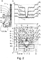
- Fig. 2 c) shows, for each scan plane A, B, C, D, several reflection points P A , P B , P C , P D lie next to one another in the transverse direction of the respective scan plane A, B, C, D.
- the transverse direction of the respective scan plane A, B, C, D is the direction of the scan plane A, B, C, D transverse to the direction of travel F of the agricultural machine 1.
- the laser-based sensor system 6 scans the apron area 7 here and preferably through it starting from the fact that it periodically emits transmission pulses from transmission beams in at least one transmission direction onto the apron area 7, the transmission pulses being reflected at said reflection points P A , P B , P C , P D of the apron area 7 and received as echo pulses by the laser-based sensor system 6.
- a reflection signal representing a spatial distance value W A , W B , W C , W D is assigned to each reflection point P A , P B , P C , P D.
- a spatial lender Distance value W A , W B , W C , W D is a value for the distance between working machine 1 and the respective reflection point P A , P B , P C , P D.
- the reflection points P A are each assigned a distance value W A
- the reflection points P B are each assigned a distance value W B
- the reflection points Pc are each assigned a distance value Wc
- the reflection points P D are each assigned a distance value W D.
- the distance is in particular the distance from a reference line RL running transversely, in particular orthogonally, to the direction of travel F, in particular an edge of the work machine 1, here for example a front edge of the attachment, to the respective reflection point P A , P B , P C , P D .
- the distance from the reference line RL to the respective reflection point P A , P B , P C , P D is preferably a horizontal distance in the direction of travel F.
- the distance can also be the distance from a reference point RP, in particular a central point on the work machine, here for example the point of the laser-based sensor system 6 from which the respective transmission beam is emitted to the respective reflection point P A , P B , P C , P D.
- the distance is not measured horizontally, but in a direction at an angle to the horizontal and vertical.
- the value of the latter distance from the reference point RP to the respective reflection point P A , P B , P C , P D as a spatial distance value W A , W B , W C , W D via a calculation rule that includes in particular an angle correction the value of the horizontal distance in the direction of travel F from the reference line RL to the respective reflection point P A , P B , P C , P D can be determined.
- the reflection signal is understood here to mean a signal or information which, as a result of the scanning, comprises a parameter value of at least one parameter from which the value for the spatial distance to a reflection point P A , P B , P C , P is derived D can be determined.
- One such parameter is, to name just a few examples, in particular the pulse duration from the transmission of the transmission pulse to the reception of the echo pulse, the phase shift between the transmitted transmission pulse and the received echo pulse or the difference in the signal strength of the received echo pulse to that of the transmitted one Transmission pulse.
- a reflection signal can also be a signal or information that directly contains the value for the spatial distance to the respective reflection point P A , P B , P C , P D.
- the laser-based sensor system 6, in particular the control arrangement 6a due to a change or distortion of the reflection signals of successive scan planes A, B, C, D, in particular a change in the distance between the lines of incidence L A , L B , L C , L D of successive scan planes A, B, C, D, concludes the three-dimensional nature of the apron area 7.
- the laser-based sensor system 6 therefore deduces the three-dimensional nature of the apron area 7 in particular due to a change in distance between the lines of incidence L A , L B , L C , L D.
- the line of impact L A , L B , L C , L D in question is a calculated line which, in the transverse direction of the respective scan plane A, B, C, D, shows the course of a sequence of values of the spatial distance values W A , W B , W C , W D represented by reflection points P A , P B , P C , P D.
- the changes in distance between the lines of incidence L A , L B , L C , L D which can be present over the course of the lines of incidence L A , L B , L C , L D , result as follows. If the scan planes A, B, C, D meet the apron area 7 at different distances from the work machine 1, the impingement lines L A , L B , L C , L D of successive scan planes A, B, C, D have a distance from one another, wherein this distance can change over its course or the course in the transverse direction of the respective scan plane A, B, C, D. A change in the distance results, for example, from protruding sections or recessed sections in the entire apron area 7. A change in the distance between the impact lines L A , L B , L C , L D then indicates a deviation in the three-dimensional nature of the apron area 7.
- Figure 2b shows an example of a coordinate system in which the spatial distance values W A , W B , W C , W D (y-axis) per scan plane A, B, C, D over a direction transverse to the direction of travel F (x-axis) are applied.
- the spatial distance values W A , W B , W C , W D of all scan planes A, B, C, D lie along the respective impingement line L A , L B , L C , L D.
- the line of incidence L A , L B , L C , L D is a calculated line that follows the course of the distance values in a coordinate system, here a Cartesian coordinate system W A , W B , W C , W D of the respective scan plane A, B, C, D follows.
- the line of incidence L A , L B , L C , L D is, in particular, a distance value average line.
- the spatial distance values can thus be averaged sector by sector, so that for each sector S an average value for the distance values in this sector results.
- the distance value average line connects these average values.
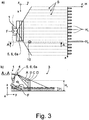
- a sector S is for example how Fig. 3a ) shows a section in the direction of the x-axis of the coordinate system and / or a section along the transverse extension of the respective scan plane A, B, C, D.
- the laser-based sensor system 6 is here and preferably designed in such a way that in the apron area harvested crop 8 (stubble), standing crop 9, opposite harvested and / or standing crop 8, 9 vertically protruding obstacles 10 such as power poles, fence posts or the like, roads 11 and / or the transition from headland 12 to standing crop 9.
- the different distances between the lines of incidence L A , L B , L C , L D of successive scan planes A, B, C, D result from the fact that the scan planes A, B, C, D are preferably aligned such that they hit the field level or the horizontal envelope surface of the standing stock 9 at a relatively flat angle. This is why the scan levels A, B, C, D spread out relatively wide when the crop 8 is harvested or when there is a road 11 ( Fig. 1a ) and 2c)).
- the scan planes A, B, C, D spread out relatively widely, but less than with harvested stand 8, since with standing stand 9 the distance from the point from which the transmission beams are sent to the scanned envelope surface is shorter than the field plane ( Figure 1b ) and 2c)).
- the scan planes A, B, C, D spread even less when they hit a vertical object from the side, for example an obstacle 10 ( Figure 1c ) and 2c)) or the lateral envelope of standing crop 9 in the area of the transition from headland 12 to standing crop 9 ( Fig. 1d )).
- the distance between the impingement lines L A , L B , L C , L D of successive scan planes A, B, C, D increases with decreasing distance of the working machine 1 from a crop 8 that is harvested and / or standing opposite , 9 vertically protruding obstacle 10 is increasingly reduced when the obstacle 10 is detected from the side.
- the laser-based sensor system 6 detects a large number of reflection points P A lying next to one another in the transverse direction of the respective scan plane A, B, C, D during the scanning of the apron area 7 for each scan plane A, B, C, D , P B , P C , P D. Since the scan planes A, B, C, D are inclined with respect to the horizontal, the reflection points P A , P B , P C , P D do not necessarily lie exactly next to one another in a vertical projection, but can also scatter. The degree of scattering depends on the object being scanned, as will be explained below.
- the scanned surface is relatively transparent, that is, plant parts lying further in front or higher and sometimes plant parts further back or deeper are recorded, so that fewer reflection points P A , P B , P C , P D are in the same plane lie, whereby the corresponding distance values W A , W B , W C , W D also vary more strongly. It hardly matters whether the standing stock 9 is recorded from above or from the side.
- the scanned surface is also relatively dense and uniform, so that here too a relatively large number of reflection points P A , P B , P C , P D lie in the same plane, whereby the corresponding distance values W A , W B , W C , W D are relatively similar.
- the laser-based sensor system 6, in particular the control arrangement 6a of the laser-based sensor system 6, from the distance between the lines of incidence L A , L B , L C , L D of successive scan planes A, B, C , D concludes the alignment of an obstacle 10 protruding vertically in relation to the harvested and / or standing crop 8, 9.
- the orientation means the orientation in space (horizontal, vertical, oblique).
- an obstacle 10 such as a utility pole or fence post has a substantially vertical orientation.
- the scan planes A, B, C, D spread out less widely when they hit a vertical object from the side, as explained above, than when they hit an object from above.
- the laser-based sensor system 6, in particular the control arrangement 6a of the laser-based sensor system 6, is based on the distance between the impingement lines L A , L B , L C , L D of successive scan planes A, B , C, D recognizes whether an object has been detected from above or from the side.
- the scan planes A, B, C, D spread out less when they hit a vertical object from the side than when they hit an object from above.
- Fig. 3 shows, is here and preferably the laser-based sensor system 6, in particular the control arrangement 6a of the laser-based sensor system 6, also able to use the spatial distance values W A , W B , W C , W D of successive scan planes A, B, C, D, in particular from the spatial distance values W A , W B , W C , W D of all scan planes A, B, C, D, in the apron area 7 height values H, in particular for the height of a harvested stand 8, the height H 1 of a standing crop 9 and / or the height H 2 of an obstacle 10 protruding vertically in relation to the harvested and / or standing crop 8, 9.
- the height H 1 of the standing structure 9 and the height H 2 of an obstacle 10 are determined, in each case for several sectors S.
- the laser-based sensor system 6, in particular the control arrangement 6a of the laser-based sensor system 6, can now also determine the degree of scattering in addition to the changes in distance between the lines of incidence L A , L B , L C , L D of successive scan planes A, B, C, D the spatial distance values W A , W B , W C , W D , in particular the degree of dispersion of the spatial distance values W A , W B , W C , W D around the respective line of impact L A , L B , L C , L D , and / or the height values H, in particular for the height of a harvested stand 8, the height H 1 of a standing stand 9 and / or the height H 2 of an obstacle 10 protruding vertically from the harvested and / or standing stand 8, 9, in order to infer the three-dimensional nature of the apron area 7.
- an obstacle 10 protruding vertically from the harvested and / or standing crop 8, 9 is recognized by the laser-based sensor system 6, in particular by the control arrangement 6a of the laser-based sensor system 6, here and preferably the generation of at least one control action by the driver assistance system 4 causes.
- the control action is, for example, a steering and / or braking process.
- the self-propelled agricultural working machine 1 is claimed as such for carrying out a method according to the proposal explained above. Reference may be made to all relevant statements.
Landscapes
- Physics & Mathematics (AREA)
- Engineering & Computer Science (AREA)
- Electromagnetism (AREA)
- Radar, Positioning & Navigation (AREA)
- Computer Networks & Wireless Communication (AREA)
- General Physics & Mathematics (AREA)
- Remote Sensing (AREA)
- Life Sciences & Earth Sciences (AREA)
- Environmental Sciences (AREA)
- Soil Sciences (AREA)
- Mechanical Engineering (AREA)
- Traffic Control Systems (AREA)
- Guiding Agricultural Machines (AREA)
- Control Of Position, Course, Altitude, Or Attitude Of Moving Bodies (AREA)
Applications Claiming Priority (1)
| Application Number | Priority Date | Filing Date | Title |
|---|---|---|---|
| DE102019112584.7A DE102019112584A1 (de) | 2019-05-14 | 2019-05-14 | Verfahren für den Betrieb einer selbstfahrenden landwirtschaftlichen Arbeitsmaschine |
Publications (2)
| Publication Number | Publication Date |
|---|---|
| EP3738420A1 true EP3738420A1 (fr) | 2020-11-18 |
| EP3738420B1 EP3738420B1 (fr) | 2024-01-24 |
Family
ID=69526056
Family Applications (1)
| Application Number | Title | Priority Date | Filing Date |
|---|---|---|---|
| EP20155863.2A Active EP3738420B1 (fr) | 2019-05-14 | 2020-02-06 | Procédé de fonctionnement d'un engin agricole automatique |
Country Status (2)
| Country | Link |
|---|---|
| EP (1) | EP3738420B1 (fr) |
| DE (1) | DE102019112584A1 (fr) |
Cited By (2)
| Publication number | Priority date | Publication date | Assignee | Title |
|---|---|---|---|---|
| CN113534184A (zh) * | 2021-07-13 | 2021-10-22 | 华南农业大学 | 一种激光感知的农业机器人空间定位方法 |
| EP4155775A1 (fr) * | 2021-09-22 | 2023-03-29 | CLAAS E-Systems GmbH | Procédé d'identification d'objets, ainsi que machine de travail agricole |
Families Citing this family (1)
| Publication number | Priority date | Publication date | Assignee | Title |
|---|---|---|---|---|
| DE102021121296A1 (de) | 2021-08-17 | 2023-02-23 | Claas Selbstfahrende Erntemaschinen Gmbh | Verfahren für den Betrieb einer selbstfahrenden landwirtschaftlichen Erntemaschine sowie selbstfahrende landwirtschaftliche Erntemaschine |
Citations (4)
| Publication number | Priority date | Publication date | Assignee | Title |
|---|---|---|---|---|
| EP2306217A1 (fr) * | 2009-09-30 | 2011-04-06 | Sick Ag | Détermination d'un environnement |
| DE102015118767A1 (de) | 2015-11-03 | 2017-05-04 | Claas Selbstfahrende Erntemaschinen Gmbh | Umfelddetektionseinrichtung für landwirtschaftliche Arbeitsmaschine |
| EP3300561A1 (fr) * | 2016-09-30 | 2018-04-04 | CLAAS Selbstfahrende Erntemaschinen GmbH | Machine agricole automotrice |
| DE102017122710A1 (de) * | 2017-09-29 | 2019-04-04 | Claas E-Systems Kgaa Mbh & Co. Kg | Verfahren für den Betrieb einer selbstfahrenden landwirtschaftlichen Arbeitsmaschine |
-
2019
- 2019-05-14 DE DE102019112584.7A patent/DE102019112584A1/de not_active Withdrawn
-
2020
- 2020-02-06 EP EP20155863.2A patent/EP3738420B1/fr active Active
Patent Citations (4)
| Publication number | Priority date | Publication date | Assignee | Title |
|---|---|---|---|---|
| EP2306217A1 (fr) * | 2009-09-30 | 2011-04-06 | Sick Ag | Détermination d'un environnement |
| DE102015118767A1 (de) | 2015-11-03 | 2017-05-04 | Claas Selbstfahrende Erntemaschinen Gmbh | Umfelddetektionseinrichtung für landwirtschaftliche Arbeitsmaschine |
| EP3300561A1 (fr) * | 2016-09-30 | 2018-04-04 | CLAAS Selbstfahrende Erntemaschinen GmbH | Machine agricole automotrice |
| DE102017122710A1 (de) * | 2017-09-29 | 2019-04-04 | Claas E-Systems Kgaa Mbh & Co. Kg | Verfahren für den Betrieb einer selbstfahrenden landwirtschaftlichen Arbeitsmaschine |
Cited By (3)
| Publication number | Priority date | Publication date | Assignee | Title |
|---|---|---|---|---|
| CN113534184A (zh) * | 2021-07-13 | 2021-10-22 | 华南农业大学 | 一种激光感知的农业机器人空间定位方法 |
| CN113534184B (zh) * | 2021-07-13 | 2023-08-29 | 华南农业大学 | 一种激光感知的农业机器人空间定位方法 |
| EP4155775A1 (fr) * | 2021-09-22 | 2023-03-29 | CLAAS E-Systems GmbH | Procédé d'identification d'objets, ainsi que machine de travail agricole |
Also Published As
| Publication number | Publication date |
|---|---|
| DE102019112584A1 (de) | 2020-11-19 |
| EP3738420B1 (fr) | 2024-01-24 |
Similar Documents
| Publication | Publication Date | Title |
|---|---|---|
| EP3866593B1 (fr) | Procédé d'épandage d'un produit de pulvérisation sur un champ | |
| EP3417686B1 (fr) | Engin agricole | |
| EP3932162B1 (fr) | Système de détermination de la position d'une caméra dans un dispositif caméra par rapport à un niveau de plancher | |
| DE19743884A1 (de) | Vorrichtung und Verfahren zur berührungslosen Erkennung von Bearbeitungsgrenzen oder entsprechenden Leitgrößen | |
| DE102016118651A1 (de) | Selbstfahrende landwirtschaftliche Arbeitsmaschine | |
| EP1630574A2 (fr) | Dispositif monté sur des machines agricoles destiné au balayage sans contact de contours sýétendant sur le sol | |
| EP3530098B1 (fr) | Procédé de détermination de la densité de pâturage d'une culture | |
| DE102017217391A1 (de) | Landwirtschaftliches Arbeitsfahrzeug | |
| EP3738420B1 (fr) | Procédé de fonctionnement d'un engin agricole automatique | |
| EP3786664B1 (fr) | Procédé d'évaluation de signal des signaux d'un télémètre | |
| EP3747248A1 (fr) | Agencement de capteurs pour un véhicule agricole | |
| WO2020164834A1 (fr) | Détermination de trajectoire pour machines agricoles au moyen de cartes tramées | |
| EP4064815A1 (fr) | Procédé de traitement de plantes dans un champ | |
| DE102018204301B4 (de) | Verfahren zum Ermitteln einer Bestandhöhe von Feldpflanzen | |
| DE102018104207A1 (de) | Selbstfahrende Erntemaschine | |
| DE10346541A1 (de) | Einrichtung und Verfahren zum Messen der Ausbildung von Pflanzenbeständen | |
| EP4052550B1 (fr) | Dispositif de compensation de la suspension latérale pour la viticulture | |
| EP4155775A1 (fr) | Procédé d'identification d'objets, ainsi que machine de travail agricole | |
| EP4154698B1 (fr) | Procédé de détection du niveau du sol sur une surface à traiter par une machine de travail agricole | |
| EP3786663B1 (fr) | Procédé d'évaluation des signaux d'un télémètre | |
| DE102021125362A1 (de) | Vorrichtung und Verfahren zur Bestimmung einer Lage einer Pflanzenreihe und/oder eines Pflanzenreihenrasters | |
| WO2021244887A1 (fr) | Procédé de culture de récoltes en rangées | |
| EP3732950B1 (fr) | Procédé de fonctionnement d'un engin agricole automatique | |
| DE102021124478A1 (de) | Verfahren zur Fruchtartunterscheidung von Pflanzen innerhalb eines Feldbestandes | |
| DE102020129554A1 (de) | Vorrichtung zur Verwendung in landwirtschaftlichen Anwendungen, Verfahren zur Bestimmung von Positionen von Saatgut und landwirtschaftliche Arbeitsmaschine |
Legal Events
| Date | Code | Title | Description |
|---|---|---|---|
| PUAI | Public reference made under article 153(3) epc to a published international application that has entered the european phase |
Free format text: ORIGINAL CODE: 0009012 |
|
| STAA | Information on the status of an ep patent application or granted ep patent |
Free format text: STATUS: THE APPLICATION HAS BEEN PUBLISHED |
|
| AK | Designated contracting states |
Kind code of ref document: A1 Designated state(s): AL AT BE BG CH CY CZ DE DK EE ES FI FR GB GR HR HU IE IS IT LI LT LU LV MC MK MT NL NO PL PT RO RS SE SI SK SM TR |
|
| AX | Request for extension of the european patent |
Extension state: BA ME |
|
| STAA | Information on the status of an ep patent application or granted ep patent |
Free format text: STATUS: REQUEST FOR EXAMINATION WAS MADE |
|
| 17P | Request for examination filed |
Effective date: 20210518 |
|
| RBV | Designated contracting states (corrected) |
Designated state(s): AL AT BE BG CH CY CZ DE DK EE ES FI FR GB GR HR HU IE IS IT LI LT LU LV MC MK MT NL NO PL PT RO RS SE SI SK SM TR |
|
| STAA | Information on the status of an ep patent application or granted ep patent |
Free format text: STATUS: EXAMINATION IS IN PROGRESS |
|
| 17Q | First examination report despatched |
Effective date: 20221214 |
|
| P01 | Opt-out of the competence of the unified patent court (upc) registered |
Effective date: 20230516 |
|
| REG | Reference to a national code |
Ref country code: DE Ref legal event code: R079 Free format text: PREVIOUS MAIN CLASS: A01B0069040000 Ipc: A01B0069000000 Ref country code: DE Ref legal event code: R079 Ref document number: 502020006794 Country of ref document: DE Free format text: PREVIOUS MAIN CLASS: A01B0069040000 Ipc: A01B0069000000 |
|
| RIC1 | Information provided on ipc code assigned before grant |
Ipc: G01S 17/931 20200101ALI20230926BHEP Ipc: G01S 17/89 20200101ALI20230926BHEP Ipc: G01S 17/88 20060101ALI20230926BHEP Ipc: G01S 17/42 20060101ALI20230926BHEP Ipc: A01D 41/127 20060101ALI20230926BHEP Ipc: A01B 69/04 20060101ALI20230926BHEP Ipc: A01B 69/00 20060101AFI20230926BHEP |
|
| GRAP | Despatch of communication of intention to grant a patent |
Free format text: ORIGINAL CODE: EPIDOSNIGR1 |
|
| STAA | Information on the status of an ep patent application or granted ep patent |
Free format text: STATUS: GRANT OF PATENT IS INTENDED |
|
| INTG | Intention to grant announced |
Effective date: 20231103 |
|
| GRAS | Grant fee paid |
Free format text: ORIGINAL CODE: EPIDOSNIGR3 |
|
| GRAA | (expected) grant |
Free format text: ORIGINAL CODE: 0009210 |
|
| STAA | Information on the status of an ep patent application or granted ep patent |
Free format text: STATUS: THE PATENT HAS BEEN GRANTED |
|
| AK | Designated contracting states |
Kind code of ref document: B1 Designated state(s): AL AT BE BG CH CY CZ DE DK EE ES FI FR GB GR HR HU IE IS IT LI LT LU LV MC MK MT NL NO PL PT RO RS SE SI SK SM TR |
|
| REG | Reference to a national code |
Ref country code: GB Ref legal event code: FG4D Free format text: NOT ENGLISH |
|
| REG | Reference to a national code |
Ref country code: CH Ref legal event code: EP |
|
| REG | Reference to a national code |
Ref country code: IE Ref legal event code: FG4D Free format text: LANGUAGE OF EP DOCUMENT: GERMAN |
|
| REG | Reference to a national code |
Ref country code: DE Ref legal event code: R096 Ref document number: 502020006794 Country of ref document: DE |
|
| REG | Reference to a national code |
Ref country code: LT Ref legal event code: MG9D |
|
| REG | Reference to a national code |
Ref country code: NL Ref legal event code: MP Effective date: 20240124 |
|
| PG25 | Lapsed in a contracting state [announced via postgrant information from national office to epo] |
Ref country code: NL Free format text: LAPSE BECAUSE OF FAILURE TO SUBMIT A TRANSLATION OF THE DESCRIPTION OR TO PAY THE FEE WITHIN THE PRESCRIBED TIME-LIMIT Effective date: 20240124 |
|
| PG25 | Lapsed in a contracting state [announced via postgrant information from national office to epo] |
Ref country code: NL Free format text: LAPSE BECAUSE OF FAILURE TO SUBMIT A TRANSLATION OF THE DESCRIPTION OR TO PAY THE FEE WITHIN THE PRESCRIBED TIME-LIMIT Effective date: 20240124 |
|
| PG25 | Lapsed in a contracting state [announced via postgrant information from national office to epo] |
Ref country code: IS Free format text: LAPSE BECAUSE OF FAILURE TO SUBMIT A TRANSLATION OF THE DESCRIPTION OR TO PAY THE FEE WITHIN THE PRESCRIBED TIME-LIMIT Effective date: 20240524 |
|
| PG25 | Lapsed in a contracting state [announced via postgrant information from national office to epo] |
Ref country code: LT Free format text: LAPSE BECAUSE OF FAILURE TO SUBMIT A TRANSLATION OF THE DESCRIPTION OR TO PAY THE FEE WITHIN THE PRESCRIBED TIME-LIMIT Effective date: 20240124 |
|
| PG25 | Lapsed in a contracting state [announced via postgrant information from national office to epo] |
Ref country code: GR Free format text: LAPSE BECAUSE OF FAILURE TO SUBMIT A TRANSLATION OF THE DESCRIPTION OR TO PAY THE FEE WITHIN THE PRESCRIBED TIME-LIMIT Effective date: 20240425 |
|
| PG25 | Lapsed in a contracting state [announced via postgrant information from national office to epo] |
Ref country code: HR Free format text: LAPSE BECAUSE OF FAILURE TO SUBMIT A TRANSLATION OF THE DESCRIPTION OR TO PAY THE FEE WITHIN THE PRESCRIBED TIME-LIMIT Effective date: 20240124 Ref country code: RS Free format text: LAPSE BECAUSE OF FAILURE TO SUBMIT A TRANSLATION OF THE DESCRIPTION OR TO PAY THE FEE WITHIN THE PRESCRIBED TIME-LIMIT Effective date: 20240424 |
|
| PG25 | Lapsed in a contracting state [announced via postgrant information from national office to epo] |
Ref country code: ES Free format text: LAPSE BECAUSE OF FAILURE TO SUBMIT A TRANSLATION OF THE DESCRIPTION OR TO PAY THE FEE WITHIN THE PRESCRIBED TIME-LIMIT Effective date: 20240124 |
|
| PG25 | Lapsed in a contracting state [announced via postgrant information from national office to epo] |
Ref country code: RS Free format text: LAPSE BECAUSE OF FAILURE TO SUBMIT A TRANSLATION OF THE DESCRIPTION OR TO PAY THE FEE WITHIN THE PRESCRIBED TIME-LIMIT Effective date: 20240424 Ref country code: NO Free format text: LAPSE BECAUSE OF FAILURE TO SUBMIT A TRANSLATION OF THE DESCRIPTION OR TO PAY THE FEE WITHIN THE PRESCRIBED TIME-LIMIT Effective date: 20240424 Ref country code: LT Free format text: LAPSE BECAUSE OF FAILURE TO SUBMIT A TRANSLATION OF THE DESCRIPTION OR TO PAY THE FEE WITHIN THE PRESCRIBED TIME-LIMIT Effective date: 20240124 Ref country code: IS Free format text: LAPSE BECAUSE OF FAILURE TO SUBMIT A TRANSLATION OF THE DESCRIPTION OR TO PAY THE FEE WITHIN THE PRESCRIBED TIME-LIMIT Effective date: 20240524 Ref country code: HR Free format text: LAPSE BECAUSE OF FAILURE TO SUBMIT A TRANSLATION OF THE DESCRIPTION OR TO PAY THE FEE WITHIN THE PRESCRIBED TIME-LIMIT Effective date: 20240124 Ref country code: GR Free format text: LAPSE BECAUSE OF FAILURE TO SUBMIT A TRANSLATION OF THE DESCRIPTION OR TO PAY THE FEE WITHIN THE PRESCRIBED TIME-LIMIT Effective date: 20240425 Ref country code: FI Free format text: LAPSE BECAUSE OF FAILURE TO SUBMIT A TRANSLATION OF THE DESCRIPTION OR TO PAY THE FEE WITHIN THE PRESCRIBED TIME-LIMIT Effective date: 20240124 Ref country code: ES Free format text: LAPSE BECAUSE OF FAILURE TO SUBMIT A TRANSLATION OF THE DESCRIPTION OR TO PAY THE FEE WITHIN THE PRESCRIBED TIME-LIMIT Effective date: 20240124 Ref country code: BG Free format text: LAPSE BECAUSE OF FAILURE TO SUBMIT A TRANSLATION OF THE DESCRIPTION OR TO PAY THE FEE WITHIN THE PRESCRIBED TIME-LIMIT Effective date: 20240124 |
|
| PG25 | Lapsed in a contracting state [announced via postgrant information from national office to epo] |
Ref country code: PL Free format text: LAPSE BECAUSE OF FAILURE TO SUBMIT A TRANSLATION OF THE DESCRIPTION OR TO PAY THE FEE WITHIN THE PRESCRIBED TIME-LIMIT Effective date: 20240124 Ref country code: PT Free format text: LAPSE BECAUSE OF FAILURE TO SUBMIT A TRANSLATION OF THE DESCRIPTION OR TO PAY THE FEE WITHIN THE PRESCRIBED TIME-LIMIT Effective date: 20240524 |
|
| PG25 | Lapsed in a contracting state [announced via postgrant information from national office to epo] |
Ref country code: SE Free format text: LAPSE BECAUSE OF FAILURE TO SUBMIT A TRANSLATION OF THE DESCRIPTION OR TO PAY THE FEE WITHIN THE PRESCRIBED TIME-LIMIT Effective date: 20240124 Ref country code: PT Free format text: LAPSE BECAUSE OF FAILURE TO SUBMIT A TRANSLATION OF THE DESCRIPTION OR TO PAY THE FEE WITHIN THE PRESCRIBED TIME-LIMIT Effective date: 20240524 Ref country code: PL Free format text: LAPSE BECAUSE OF FAILURE TO SUBMIT A TRANSLATION OF THE DESCRIPTION OR TO PAY THE FEE WITHIN THE PRESCRIBED TIME-LIMIT Effective date: 20240124 Ref country code: LV Free format text: LAPSE BECAUSE OF FAILURE TO SUBMIT A TRANSLATION OF THE DESCRIPTION OR TO PAY THE FEE WITHIN THE PRESCRIBED TIME-LIMIT Effective date: 20240124 |
|
| REG | Reference to a national code |
Ref country code: CH Ref legal event code: PL |
|
| PG25 | Lapsed in a contracting state [announced via postgrant information from national office to epo] |
Ref country code: DK Free format text: LAPSE BECAUSE OF FAILURE TO SUBMIT A TRANSLATION OF THE DESCRIPTION OR TO PAY THE FEE WITHIN THE PRESCRIBED TIME-LIMIT Effective date: 20240124 |
|
| PG25 | Lapsed in a contracting state [announced via postgrant information from national office to epo] |
Ref country code: SM Free format text: LAPSE BECAUSE OF FAILURE TO SUBMIT A TRANSLATION OF THE DESCRIPTION OR TO PAY THE FEE WITHIN THE PRESCRIBED TIME-LIMIT Effective date: 20240124 |
|
| PG25 | Lapsed in a contracting state [announced via postgrant information from national office to epo] |
Ref country code: LU Free format text: LAPSE BECAUSE OF NON-PAYMENT OF DUE FEES Effective date: 20240206 |
|
| PG25 | Lapsed in a contracting state [announced via postgrant information from national office to epo] |
Ref country code: CH Free format text: LAPSE BECAUSE OF NON-PAYMENT OF DUE FEES Effective date: 20240229 |
|
| PG25 | Lapsed in a contracting state [announced via postgrant information from national office to epo] |
Ref country code: EE Free format text: LAPSE BECAUSE OF FAILURE TO SUBMIT A TRANSLATION OF THE DESCRIPTION OR TO PAY THE FEE WITHIN THE PRESCRIBED TIME-LIMIT Effective date: 20240124 Ref country code: CZ Free format text: LAPSE BECAUSE OF FAILURE TO SUBMIT A TRANSLATION OF THE DESCRIPTION OR TO PAY THE FEE WITHIN THE PRESCRIBED TIME-LIMIT Effective date: 20240124 |
|
| REG | Reference to a national code |
Ref country code: DE Ref legal event code: R097 Ref document number: 502020006794 Country of ref document: DE |
|
| PG25 | Lapsed in a contracting state [announced via postgrant information from national office to epo] |
Ref country code: SK Free format text: LAPSE BECAUSE OF FAILURE TO SUBMIT A TRANSLATION OF THE DESCRIPTION OR TO PAY THE FEE WITHIN THE PRESCRIBED TIME-LIMIT Effective date: 20240124 |
|
| PG25 | Lapsed in a contracting state [announced via postgrant information from national office to epo] |
Ref country code: SM Free format text: LAPSE BECAUSE OF FAILURE TO SUBMIT A TRANSLATION OF THE DESCRIPTION OR TO PAY THE FEE WITHIN THE PRESCRIBED TIME-LIMIT Effective date: 20240124 Ref country code: SK Free format text: LAPSE BECAUSE OF FAILURE TO SUBMIT A TRANSLATION OF THE DESCRIPTION OR TO PAY THE FEE WITHIN THE PRESCRIBED TIME-LIMIT Effective date: 20240124 Ref country code: LU Free format text: LAPSE BECAUSE OF NON-PAYMENT OF DUE FEES Effective date: 20240206 Ref country code: EE Free format text: LAPSE BECAUSE OF FAILURE TO SUBMIT A TRANSLATION OF THE DESCRIPTION OR TO PAY THE FEE WITHIN THE PRESCRIBED TIME-LIMIT Effective date: 20240124 Ref country code: DK Free format text: LAPSE BECAUSE OF FAILURE TO SUBMIT A TRANSLATION OF THE DESCRIPTION OR TO PAY THE FEE WITHIN THE PRESCRIBED TIME-LIMIT Effective date: 20240124 Ref country code: CZ Free format text: LAPSE BECAUSE OF FAILURE TO SUBMIT A TRANSLATION OF THE DESCRIPTION OR TO PAY THE FEE WITHIN THE PRESCRIBED TIME-LIMIT Effective date: 20240124 Ref country code: CH Free format text: LAPSE BECAUSE OF NON-PAYMENT OF DUE FEES Effective date: 20240229 |
|
| PG25 | Lapsed in a contracting state [announced via postgrant information from national office to epo] |
Ref country code: MC Free format text: LAPSE BECAUSE OF FAILURE TO SUBMIT A TRANSLATION OF THE DESCRIPTION OR TO PAY THE FEE WITHIN THE PRESCRIBED TIME-LIMIT Effective date: 20240124 |
|
| PG25 | Lapsed in a contracting state [announced via postgrant information from national office to epo] |
Ref country code: MC Free format text: LAPSE BECAUSE OF FAILURE TO SUBMIT A TRANSLATION OF THE DESCRIPTION OR TO PAY THE FEE WITHIN THE PRESCRIBED TIME-LIMIT Effective date: 20240124 |
|
| PLBE | No opposition filed within time limit |
Free format text: ORIGINAL CODE: 0009261 |
|
| STAA | Information on the status of an ep patent application or granted ep patent |
Free format text: STATUS: NO OPPOSITION FILED WITHIN TIME LIMIT |
|
| PG25 | Lapsed in a contracting state [announced via postgrant information from national office to epo] |
Ref country code: IT Free format text: LAPSE BECAUSE OF FAILURE TO SUBMIT A TRANSLATION OF THE DESCRIPTION OR TO PAY THE FEE WITHIN THE PRESCRIBED TIME-LIMIT Effective date: 20240124 |
|
| GBPC | Gb: european patent ceased through non-payment of renewal fee |
Effective date: 20240424 |
|
| PG25 | Lapsed in a contracting state [announced via postgrant information from national office to epo] |
Ref country code: IT Free format text: LAPSE BECAUSE OF FAILURE TO SUBMIT A TRANSLATION OF THE DESCRIPTION OR TO PAY THE FEE WITHIN THE PRESCRIBED TIME-LIMIT Effective date: 20240124 |
|
| 26N | No opposition filed |
Effective date: 20241025 |
|
| PG25 | Lapsed in a contracting state [announced via postgrant information from national office to epo] |
Ref country code: GB Free format text: LAPSE BECAUSE OF NON-PAYMENT OF DUE FEES Effective date: 20240424 |
|
| PG25 | Lapsed in a contracting state [announced via postgrant information from national office to epo] |
Ref country code: IE Free format text: LAPSE BECAUSE OF NON-PAYMENT OF DUE FEES Effective date: 20240206 |
|
| PG25 | Lapsed in a contracting state [announced via postgrant information from national office to epo] |
Ref country code: IE Free format text: LAPSE BECAUSE OF NON-PAYMENT OF DUE FEES Effective date: 20240206 Ref country code: GB Free format text: LAPSE BECAUSE OF NON-PAYMENT OF DUE FEES Effective date: 20240424 |
|
| PG25 | Lapsed in a contracting state [announced via postgrant information from national office to epo] |
Ref country code: SI Free format text: LAPSE BECAUSE OF FAILURE TO SUBMIT A TRANSLATION OF THE DESCRIPTION OR TO PAY THE FEE WITHIN THE PRESCRIBED TIME-LIMIT Effective date: 20240124 |
|
| PGFP | Annual fee paid to national office [announced via postgrant information from national office to epo] |
Ref country code: AT Payment date: 20250417 Year of fee payment: 5 |
|
| PG25 | Lapsed in a contracting state [announced via postgrant information from national office to epo] |
Ref country code: RO Free format text: LAPSE BECAUSE OF FAILURE TO SUBMIT A TRANSLATION OF THE DESCRIPTION OR TO PAY THE FEE WITHIN THE PRESCRIBED TIME-LIMIT Effective date: 20240124 |
|
| PG25 | Lapsed in a contracting state [announced via postgrant information from national office to epo] |
Ref country code: CY Free format text: LAPSE BECAUSE OF FAILURE TO SUBMIT A TRANSLATION OF THE DESCRIPTION OR TO PAY THE FEE WITHIN THE PRESCRIBED TIME-LIMIT; INVALID AB INITIO Effective date: 20200206 |
|
| PG25 | Lapsed in a contracting state [announced via postgrant information from national office to epo] |
Ref country code: HU Free format text: LAPSE BECAUSE OF FAILURE TO SUBMIT A TRANSLATION OF THE DESCRIPTION OR TO PAY THE FEE WITHIN THE PRESCRIBED TIME-LIMIT; INVALID AB INITIO Effective date: 20200206 |
|
| PG25 | Lapsed in a contracting state [announced via postgrant information from national office to epo] |
Ref country code: TR Free format text: LAPSE BECAUSE OF FAILURE TO SUBMIT A TRANSLATION OF THE DESCRIPTION OR TO PAY THE FEE WITHIN THE PRESCRIBED TIME-LIMIT Effective date: 20240124 |
|
| PGFP | Annual fee paid to national office [announced via postgrant information from national office to epo] |
Ref country code: DE Payment date: 20260218 Year of fee payment: 7 |
|
| PG25 | Lapsed in a contracting state [announced via postgrant information from national office to epo] |
Ref country code: AT Free format text: LAPSE BECAUSE OF NON-PAYMENT OF DUE FEES Effective date: 20250206 |
|
| PGFP | Annual fee paid to national office [announced via postgrant information from national office to epo] |
Ref country code: BE Payment date: 20260218 Year of fee payment: 7 |
|
| REG | Reference to a national code |
Ref country code: AT Ref legal event code: MM01 Ref document number: 1651396 Country of ref document: AT Kind code of ref document: T Effective date: 20250206 |
|
| PGFP | Annual fee paid to national office [announced via postgrant information from national office to epo] |
Ref country code: FR Payment date: 20260218 Year of fee payment: 7 |