EP3738457B1 - Shoe with a ventilation device switchable between fresh air supply and circulated air - Google Patents
Shoe with a ventilation device switchable between fresh air supply and circulated air Download PDFInfo
- Publication number
- EP3738457B1 EP3738457B1 EP19174048.9A EP19174048A EP3738457B1 EP 3738457 B1 EP3738457 B1 EP 3738457B1 EP 19174048 A EP19174048 A EP 19174048A EP 3738457 B1 EP3738457 B1 EP 3738457B1
- Authority
- EP
- European Patent Office
- Prior art keywords
- shoe
- air
- valve closing
- closing element
- servomotor
- Prior art date
- Legal status (The legal status is an assumption and is not a legal conclusion. Google has not performed a legal analysis and makes no representation as to the accuracy of the status listed.)
- Active
Links
Images

Classifications
-
- A—HUMAN NECESSITIES
- A43—FOOTWEAR
- A43B—CHARACTERISTIC FEATURES OF FOOTWEAR; PARTS OF FOOTWEAR
- A43B7/00—Footwear with health or hygienic arrangements
- A43B7/06—Footwear with health or hygienic arrangements ventilated
- A43B7/08—Footwear with health or hygienic arrangements ventilated with air-holes, with or without closures
- A43B7/081—Footwear with health or hygienic arrangements ventilated with air-holes, with or without closures the air being forced from outside
-
- A—HUMAN NECESSITIES
- A43—FOOTWEAR
- A43B—CHARACTERISTIC FEATURES OF FOOTWEAR; PARTS OF FOOTWEAR
- A43B3/00—Footwear characterised by the shape or the use
- A43B3/34—Footwear characterised by the shape or the use with electrical or electronic arrangements
-
- A—HUMAN NECESSITIES
- A43—FOOTWEAR
- A43B—CHARACTERISTIC FEATURES OF FOOTWEAR; PARTS OF FOOTWEAR
- A43B3/00—Footwear characterised by the shape or the use
- A43B3/34—Footwear characterised by the shape or the use with electrical or electronic arrangements
- A43B3/38—Footwear characterised by the shape or the use with electrical or electronic arrangements with power sources
-
- A—HUMAN NECESSITIES
- A43—FOOTWEAR
- A43B—CHARACTERISTIC FEATURES OF FOOTWEAR; PARTS OF FOOTWEAR
- A43B3/00—Footwear characterised by the shape or the use
- A43B3/34—Footwear characterised by the shape or the use with electrical or electronic arrangements
- A43B3/38—Footwear characterised by the shape or the use with electrical or electronic arrangements with power sources
- A43B3/42—Footwear characterised by the shape or the use with electrical or electronic arrangements with power sources where power is generated by conversion of mechanical movement to electricity, e.g. by piezoelectric means
-
- A—HUMAN NECESSITIES
- A43—FOOTWEAR
- A43B—CHARACTERISTIC FEATURES OF FOOTWEAR; PARTS OF FOOTWEAR
- A43B3/00—Footwear characterised by the shape or the use
- A43B3/34—Footwear characterised by the shape or the use with electrical or electronic arrangements
- A43B3/44—Footwear characterised by the shape or the use with electrical or electronic arrangements with sensors, e.g. for detecting contact or position
-
- A—HUMAN NECESSITIES
- A43—FOOTWEAR
- A43B—CHARACTERISTIC FEATURES OF FOOTWEAR; PARTS OF FOOTWEAR
- A43B7/00—Footwear with health or hygienic arrangements
- A43B7/06—Footwear with health or hygienic arrangements ventilated
- A43B7/08—Footwear with health or hygienic arrangements ventilated with air-holes, with or without closures
- A43B7/084—Footwear with health or hygienic arrangements ventilated with air-holes, with or without closures characterised by the location of the holes
- A43B7/085—Footwear with health or hygienic arrangements ventilated with air-holes, with or without closures characterised by the location of the holes in the upper
Definitions
- the invention relates to a shoe with a ventilation device Suction of fresh air is arranged on the outside of the shoe, a second air suction line with a second suction opening, which is arranged in the interior of the shoe, and a switching device coupling the first and second air suction lines to the air pumping device, which either the first or the second air suction line with at least one suction opening the air pumping device connects.
- Such a shoe with a ventilation device that can be switched between fresh air supply and circulating air operation is, for example, from the patent application EP 3 106 051 A1 known. It is proposed, inter alia, to use an electromagnetically controllable valve as a switching device for switching from circulating air to fresh air mode and vice versa. This document does not disclose any further details regarding the configuration of a switching device implemented by means of the electromagnetically controllable valve.
- a shoe with a ventilation device in the form of closable ventilation openings in the sole of the shoe is also known.
- the sole contains an adjusting device driven by an electric motor, which actuates a slide which, in one end position, releases the ventilation openings of the sole and closes them in the other end position.
- the electromotive adjusting device contains either a stepper motor that drives a worm shaft or a pull magnet with a return spring.
- a shoe is known with a ventilation device which has an air pump device accommodated in the shoe heel, an air supply line transporting air from the air pump device into the interior of the shoe, and an air intake line transporting air into the air pump device.
- a manually reversible switching device couples the air intake line opening into the air pumping device either with an air intake socket with a filter surface for sucking in fresh air or with a suction line that leads to an intake opening in the interior of the shoe.
- the object of the invention is to create a switchover device in a shoe that is suitable for switching between fresh air supply and circulating air operation.
- this object is achieved by a shoe with the features of claim 1 or, alternatively, a shoe with the features of claim 2.
- a shoe of the type mentioned at the outset is characterized in that the switching device has a valve closing element driven by a servomotor, which can be moved between two setting positions when the servomotor is actuated, the valve closing element in a first setting position the first air intake line with at least one of the at least one intake opening the air pumping device and separates the second air suction line from the at least one suction opening of the air pumping device and in a second setting position connects the second air suction line to at least one of the at least one suction opening of the air pumping device and separating the first air suction line from the at least one suction opening of the air pumping device, the servomotor via a coupling element with the Valve closing element is connected and the servomotor and the coupling element are designed so that the valve closing element is held in the two setting positions without energy consumption.
- the valve closing element is pivotable about an axis and has a sealing surface, the sealing surface sliding over a bearing surface of a housing when the valve closing element is pivoted, a first opening of the first air intake line and a second opening of the second air intake line opening into the bearing surface, the valve closing element in in the first set position closes the second opening with its sealing surface and releases the first opening and in the second set position closes the first opening with its sealing surface and releases the second opening.
- This preferred embodiment of the valve closing element allows a structurally simple and thus inexpensive and also robust design of the switching device with little space requirement and low mass.
- the sliding of the sealing surface on the support surface ensures static friction for better holding the valve closing element in the respective setting positions.
- the first and the second opening can each also comprise a plurality of partial openings which open into the bearing surface next to one another and are jointly closed or released by the sealing surface.
- valve closing element comprises a valve flap in the form of a plate, which can be pivoted back and forth and thereby covers an opening of the first air intake line with its one upper side in the first setting position and an opening of the second air intake line with its opposite upper side in the second setting position.
- “Maintained without energy consumption” in this context means, on the one hand, that the energy supply both to the servomotor and to a control circuit which controls this servomotor can be switched off because none Energy supply is required to maintain the respective position assumed.
- the mass of the closing element and the coupled moving parts of the switching device should be as low as possible in order to minimize forces caused by inertia.
- This configuration of the switching device with a valve closing element that can be held in the two stable setting positions without energy consumption has the advantage of low energy consumption, so that an energy storage device (for example a rechargeable battery) can be carried in the shoe.
- an energy storage device for example a rechargeable battery
- the coupling element could comprise a transmission.
- the coupling element is merely a fastening of the valve closing element directly on a shaft of the servomotor, the axis of rotation of the shaft of the servomotor corresponding to the axis about which the valve closing element can be pivoted.
- the attachment includes, for example, a hole in the Valve closing element in which the shaft is attached by means of an adhesive connection.
- the shaft can be provided with teeth or projections which engage in corresponding recesses in the bore of the valve closing element.
- the servomotor is preferably a miniature DC motor or a miniature stepper motor which is controlled by a control circuit, the control circuit being configured in such a way that the servomotor for moving the valve closing element is controlled until the valve closing element has reached the other setting position.
- a miniature motor which preferably has maximum dimensions of less than 10 mm, also contributes to the small overall size and low mass of the moving parts.
- inexpensive miniature DC motors suitable for this application which are currently used, for example, for vibration units in mobile telephones) and miniature stepper motors.
- the control circuit is coupled to a sensor device which generates a sensor signal indicating that the valve closing element has reached the first and second actuating positions.
- the sensor device comprises, for example, a mechano-electrical converter actuated by the valve closing element or the coupling element.
- the mechano-electrical converter includes, for example, one or more mechanical limit switches or other position sensors or force or pressure sensors.
- the sensor device comprises at least one sensor that detects a motor current and / or a motor voltage of the servomotor, with the aid of which a signal dependent on the motor load is generated that indicates that it has been reached indicates the first and second set position by the valve closing element.
- control circuit is configured in such a way that the servomotor for moving the valve closing element is activated for a predetermined period of time, so that the valve closing element has reached the respective other setting position before or after this period of time has elapsed.
- the servomotor is a stepper motor and the control circuit is configured in such a way that the stepper motor for moving the valve closing element is controlled in such a way that it reaches a predetermined rotational position in each case such that the valve closing element reaches the first or second setting position.
- additional sensors attached to the valve closing element can be dispensed with.
- the second suction opening is arranged in a shaft region of the shoe interior remote from the sole. This also allows an improved lowering of the air humidity in the sole area in the air circulation mode.
- a preferred development of the shoe according to the invention is characterized by an energy store for storing the energy required to operate the servomotor and to operate the control circuit, a charging circuit for charging the energy store and an energy generator coupled to the charging circuit for converting mechanical into electrical energy, the energy being obtained by deformation or movement of an element of the energy generator during a running movement.
- an energy store for storing the energy required to operate the servomotor and to operate the control circuit
- a charging circuit for charging the energy store
- an energy generator coupled to the charging circuit for converting mechanical into electrical energy, the energy being obtained by deformation or movement of an element of the energy generator during a running movement.
- the shoe preferably has a temperature sensor coupled to a control circuit of the servomotor for detecting a temperature at a predetermined point in the interior of the shoe, the control circuit being configured in such a way that when a predetermined temperature is detected in the interior of the shoe, the servomotor is controlled in such a way that the Valve closing element is moved into the first set position.
- the control circuit is further configured in such a way that when the temperature falls below a second predetermined temperature in the interior of the shoe, the servomotor is actuated in such a way that the valve closing element is moved into the second actuating position. This allows an automated switchover from fresh air supply to recirculation mode and vice versa.
- a moisture sensor for detecting a moisture value at the specified point in the interior of the shoe is coupled to the control circuit of the servomotor, the control circuit being configured such that the servomotor is also controlled as a function of the detected humidity value. This improves the automated switching from fresh air supply to recirculation mode and vice versa and increases wearing comfort.
- the air intake line opening into the intake opening 6 has a first air intake line 7 (for example a hose, in particular a plastic hose) with a suction opening 8 arranged on the outer wall of the shoe 1 and a second air intake line 9 (also a hose) with a second air intake line opening into the interior of the shoe Intake opening 10.
- the first air intake line 7 and the second air intake line 9 open into a switching device 11, which connects either the first or the second air intake line to the intake opening 6 of the air pump device 4.
- the switching device 11 connects the first air suction line 7 to the line (e.g.
- the switching device 11 connects the second air suction line 9 to the line leading to the suction opening 6, then air is sucked in from the shoe interior via the suction opening 10 opening into the shoe interior and then again via the Air pumping device 4 and the air supply line 5 are fed back into the interior of the shoe, which leads to a circulating air operation.
- the switching device 11 comprises a valve closing element driven by a servomotor, which can be moved between two setting positions when the servomotor is actuated, the valve closing element in a first setting position connecting the first air intake line 7 to the intake opening 6 of the air pumping device 4 and the second air intake line 9 from the intake opening 6 separates and in a second setting position connects the second air intake line 9 to the intake opening 6 and separates the first air intake line 7 from the intake opening 6.
- the servomotor is driven by an in Figure 2
- the control circuit 12 shown schematically is controlled and is connected to the control circuit 12 via the control and supply lines 15.
- an air intake assembly 21 is provided, which is mounted on the heel of the shoe 1 and accommodates the first air intake line 7 with the intake opening 8, the switching device 11 and the control circuit 12.
- This air intake assembly 21 is fastened during the assembly of the sole construction in such a way that the switching device 11 is coupled to the second air intake line 9 and the line leading to the intake opening 6 of the air pump device 4.
- FIG 3A shows a schematic representation of the switching device 11, each with a section of the first air suction line 7 attached to it for sucking in fresh air and the second air suction line 9 for sucking in circulating air from the interior of the shoe.
- this switching device 11 in contrast to the illustration in FIG Figure 2 shown with their underside facing up.
- the switching device 11 shown comprises a housing 13 and a servomotor 14 fastened to the housing with the supply lines 15 to the control circuit 12.
- FIG 3B shows the in Figure 3A
- the switching device shown with the housing 13 open.
- the housing 13 comprises a housing cover 13A and a housing lower shell 13B.
- the housing cover 13A has a bore onto which a check valve 16 is placed and to which the supply line to the suction opening 6 of the air pump device 4, preferably in the form of a flexible hose, is attached.
- the hoses of the first air intake line 7 and the second air intake line 9 are plugged onto the lower housing shell 13B.
- a valve closing element 17 is shown in a first setting position.
- FIG 3C shows the in the Figures 3A and 3B Switching device 11 shown in an exploded view, in which the hoses of the first air intake line 7 and the second air intake line 9 and the servomotor 14 are pulled out downwards and in which the valve closing element 17 is pulled out of the lower housing shell 13B and the check valve 16 is pulled out of the housing cover 13A upwards.
- a first opening 19 and a second opening 20, into which the first air intake line 7 and the second air intake line 9 open, can be seen in the interior of the lower housing shell 13.
- the openings 19 and 20 in turn open onto a flat support surface 25 of the lower housing shell 13B.
- a sealing surface 26 of the valve closing element 17 slides on this support surface 25.
- the servomotor 14 has a shaft 18 which protrudes into the interior of the housing 13 and on which the valve closing element 17 with the in the Figures 3B and 3C visible hole is attached and fastened.
- the shaft rotates counterclockwise by a predetermined angle
- the valve closing element 17 connected to the shaft 18 is pivoted until the sealing surface 26 on the underside of the valve closing element 17 closes the first opening 19 and thereby exposes the second opening 20.
- the sealing surface 26 slides on the bearing surface 25 of the lower housing shell.
- the servomotor 19 is a direct current miniature motor which, in one embodiment, is caused to rotate either in one direction or in the opposite direction by reversing the polarity of the voltage supply.
- the motor can contain a simple miniature gearbox.
- the miniature motor is controlled in such a way that the shaft 18 rotates either clockwise or in the opposite direction, so that the valve closing element 17 fastened on the shaft 18 is pivoted until it is in the first or the second setting position on a side wall the lower housing shell 13b strikes.
- the motor 14 is then switched off, so that the valve closing element 17 remains in the set position it has assumed.
- the control of the motor 14 takes place with a fixed predetermined period of time, which ensures complete pivoting of the valve closing element 17.
- the power of the motor 14 is dimensioned so that on the one hand it is sufficient to overcome any frictional forces, but on the other hand is so low that the motor 14 when the valve closing element 17 hits the side wall of the Lower housing shell 13B is braked.
- the control circuit 17 can have a sensor device for detecting a motor current and / or a motor voltage of the servomotor 14, with the aid of the detected currents and / or voltages being used to generate a signal which is dependent on the motor load and which the Indicates that the valve closing element 17 has reached the first and second actuating position and, depending on this, switches off the motor 14 when the actuating position is reached.
- sensors can be arranged in the housing 13, which detect the reaching of the first and second setting positions by the valve closing element 17 and transmit corresponding signals to the control circuit 12, so that the servomotor 14 is switched off when the setting positions are reached.
- the switchover between fresh air supply and circulating air operation takes place as a function of temperatures and / or humidity values, which are detected by sensors in the interior of the shoe and / or on the exterior of the shoe.
- Figure 1 shows schematically a combination of temperature and humidity sensor 22 attached to the heel area of the shoe 1
- Figure 4 a temperature and humidity sensor 23, which is arranged in the inner sole of the shoe and is connected to the control circuit 12 via signal lines 24, is shown schematically.
- the switchover from fresh air mode to air circulation mode takes place as a function of a temperature in the interior of the shoe detected by the sensor 23 in such a way that, when a predetermined temperature is detected, the servomotor 14 is controlled in such a way that the valve closing element 17 is moved into the first setting position, and that when it is detected that the temperature falls below a second predetermined temperature, the servomotor 14 is activated in such a way that the valve closing element 17 is moved into the second set position.
- control can be carried out as a function of the moisture measured in the interior of the shoe by the sensor 23.
- switching from recirculating air to fresh air operation can be triggered with increasing humidity at a lower temperature measured in the interior.
- the switchover from fresh air mode to circulating mode and vice versa can also take place as a function of an outside temperature or, alternatively, solely as a function of a measured outside temperature, in which case the sensor in the shoe interior could be omitted in the latter case.
- a switch is made, for example, to recirculation mode if the outside temperature falls below a predetermined value at which a supply of fresh air would be perceived as unpleasant by the wearer of the shoe.
- the shoe according to the invention has an energy store, not shown in the figures, for storing the energy required to operate the servomotor 14 and to operate the control circuit 12, for example a battery or an accumulator.
- a charging circuit is preferably provided for recharging the fully or partially discharged energy store.
- the charging circuit is preferably coupled to an energy generator for converting mechanical energy into electrical energy.
- the mechanical energy is obtained by deforming or moving an element of the energy generator during a running movement.
- the element comprises a permanent magnet and a coil, which are brought into a relative movement to one another with the aid of the running movement and a corresponding gear, mechanical energy being converted into electrical energy by induction.
- electrical energy can be generated using a deformed piezoelectric Elements can be obtained.
- a further energy generator can also be provided which converts thermal energy into electrical energy, for example by utilizing the temperature difference between the interior of the shoe and the surroundings of the shoe.
Landscapes
- Engineering & Computer Science (AREA)
- Microelectronics & Electronic Packaging (AREA)
- Health & Medical Sciences (AREA)
- Epidemiology (AREA)
- General Health & Medical Sciences (AREA)
- Public Health (AREA)
- Footwear And Its Accessory, Manufacturing Method And Apparatuses (AREA)
Description
Die Erfindung betrifft einen Schuh mit einer Belüftungseinrichtung, wobei die Belüftungseinrichtung eine Luftpumpvorrichtung, eine Luft von der Luftpumpvorrichtung in den Schuhinnenraum transportierende Luftzufuhrleitung und eine Luft in die Luftpumpvorrichtung transportierende Luftansaugleitung aufweist, wobei die Luftansaugleitung aufweist: eine erste Luftansaugleitung mit einer ersten Ansaugöffnung, die zum Ansaugen von Frischluft am Außenbereich des Schuhs angeordnet ist, eine zweite Luftansaugleitung mit einer zweiten Ansaugöffnung, die im Schuhinnenraum angeordnet ist, und eine die erste und die zweite Luftansaugleitung mit der Luftpumpvorrichtung koppelnde Umschaltvorrichtung, die entweder die erste oder die zweite Luftansaugleitung mit wenigstens einer Ansaugöffnung der Luftpumpvorrichtung verbindet.The invention relates to a shoe with a ventilation device Suction of fresh air is arranged on the outside of the shoe, a second air suction line with a second suction opening, which is arranged in the interior of the shoe, and a switching device coupling the first and second air suction lines to the air pumping device, which either the first or the second air suction line with at least one suction opening the air pumping device connects.
Ein derartiger Schuh mit einer zwischen Frischluftzufuhr und Umluftbetrieb umschaltbaren Belüftungseinrichtung ist beispielsweise aus der Patentanmeldung
Aus der
Aus der
Ausgehend von diesem Stand der Technik ist es Aufgabe der Erfindung, eine für die Umschaltung zwischen Frischluftzufuhr und Umluftbetrieb geeignete Umschaltvorrichtung in einem Schuh zu schaffen.Based on this prior art, the object of the invention is to create a switchover device in a shoe that is suitable for switching between fresh air supply and circulating air operation.
Diese Aufgabe wird erfindungsgemäß durch einen Schuh mit den Merkmalen des Anspruchs 1 oder alternativ einen Schuh mit den Merkmalen des Anspruchs 2 gelöst.According to the invention, this object is achieved by a shoe with the features of
Ein Schuh der eingangs genannten Art ist erfindungsgemäß dadurch gekennzeichnet, dass die Umschaltvorrichtung ein von einem Stellmotor angetriebenes Ventilschließelement aufweist, das bei Betätigen des Stellmotors zwischen zwei Stellpositionen bewegbar ist, wobei das Ventilschließelement in einer ersten Stellposition die erste Luftansaugleitung mit wenigstens einer der wenigstens einen Ansaugöffnung der Luftpumpvorrichtung verbindet und die zweite Luftansaugleitung von der wenigstens einen Ansaugöffnung der Luftpumpvorrichtung trennt und in einer zweiten Stellposition die zweite Luftansaugleitung mit wenigstens einer der wenigstens einen Ansaugöffnung der Luftpumpvorrichtung verbindet und die erste Luftansaugleitung von der wenigstens einen Ansaugöffnung der Luftpumpvorrichtung trennt, wobei der Stellmotor über ein Koppelelement mit dem Ventilschließelement verbunden ist und der Stellmotor und das Koppelelement so ausgebildet sind, dass das Ventilschließelement in den beiden Stellpositionen ohne Energieverbrauch gehalten wird. Das Ventilschließelement ist um eine Achse schwenkbar und weist eine Dichtfläche auf, wobei die Dichtfläche beim Schwenken des Ventilschließelement über eine Auflagefläche eines Gehäuses gleitet, wobei in die Auflagefläche eine erste Öffnung der ersten Luftansaugleitung und eine zweite Öffnung der zweiten Luftansaugleitung münden, wobei das Ventilschließelement in der ersten Stellposition die zweite Öffnung mit seiner Dichtfläche verschließt und die erste Öffnung freigibt und in der zweiten Stellposition die erste Öffnung mit seiner Dichtfläche verschließt und die zweite Öffnung freigibt. Diese bevorzugte Ausgestaltung des Ventilschließelements erlaubt eine konstruktiv einfache und somit kostengünstige und darüber hinaus robuste Gestaltung der Umschaltvorrichtung bei geringem Platzbedarf und geringer Masse. Außerdem sorgt das Gleiten der Dichtfläche auf der Auflagefläche für eine Haftreibung zum besseren Halten des Ventilschließelements in den jeweiligen Stellpositionen. Die erste und die zweite Öffnung können jeweils auch mehrere Teilöffnungen umfassen, die nebeneinander in die Auflagefläche münden und gemeinsam von der Dichtfläche verschlossen oder freigegeben werden.According to the invention, a shoe of the type mentioned at the outset is characterized in that the switching device has a valve closing element driven by a servomotor, which can be moved between two setting positions when the servomotor is actuated, the valve closing element in a first setting position the first air intake line with at least one of the at least one intake opening the air pumping device and separates the second air suction line from the at least one suction opening of the air pumping device and in a second setting position connects the second air suction line to at least one of the at least one suction opening of the air pumping device and separating the first air suction line from the at least one suction opening of the air pumping device, the servomotor via a coupling element with the Valve closing element is connected and the servomotor and the coupling element are designed so that the valve closing element is held in the two setting positions without energy consumption. The valve closing element is pivotable about an axis and has a sealing surface, the sealing surface sliding over a bearing surface of a housing when the valve closing element is pivoted, a first opening of the first air intake line and a second opening of the second air intake line opening into the bearing surface, the valve closing element in in the first set position closes the second opening with its sealing surface and releases the first opening and in the second set position closes the first opening with its sealing surface and releases the second opening. This preferred embodiment of the valve closing element allows a structurally simple and thus inexpensive and also robust design of the switching device with little space requirement and low mass. In addition, the sliding of the sealing surface on the support surface ensures static friction for better holding the valve closing element in the respective setting positions. The first and the second opening can each also comprise a plurality of partial openings which open into the bearing surface next to one another and are jointly closed or released by the sealing surface.
Alternativ umfasst das Ventilschließelement eine Ventilklappe in Form einer Platte, die hin und her geschwenkt werden kann und dabei in der ersten Stellposition mit ihrer einen Oberseite eine Öffnung der ersten Luftansaugleitung abdeckt und in der zweiten Stellposition mit ihrer gegenüberliegenden Oberseite eine Öffnung der zweiten Luftansaugleitung abdeckt.Alternatively, the valve closing element comprises a valve flap in the form of a plate, which can be pivoted back and forth and thereby covers an opening of the first air intake line with its one upper side in the first setting position and an opening of the second air intake line with its opposite upper side in the second setting position.
"Ohne Energieverbrauch gehalten" bedeutet in diesem Zusammenhang einerseits, dass die Energieversorgung sowohl des Stellmotors als auch einer diesen Stellmotor ansteuernden Steuerschaltung abgeschaltet sein können, weil keine Energiezufuhr erforderlich ist, um die jeweils eingenommene Stellposition beizubehalten. Andererseits bedeutet dies, dass die Kombination von Stellmotor, Koppelelement und Ventilschließelement mechanisch-konstruktiv so ausgebildet ist, dass auch bei den im Laufbetrieb auftretenden Erschütterungen keine wesentliche Änderung der Position des Ventilschließelements stattfinden kann. Dies bedeutet unter anderem, dass für eine geringe Masse des Ventilschließelements und der bewegbaren Teile des Koppelelements und des Stellmotors (z.B. Rotor) bei ausreichender Reibung, insbesondere Haftreibung, des Schließelements gegenüber den feststehenden Bestandteilen der Umschaltvorrichtung, an denen das Ventilschließelement in den Stellpositionen anliegt, und den feststehenden Teilen des Stellmotors (z.B. Stator) gesorgt werden muss. Grundsätzlich gilt, dass die Masse des Schließelements und der angekoppelten mitbewegten Teile der Umschaltvorrichtung so gering wie möglich sein sollte, um trägheitsbedingte Kräfte zu minimieren."Maintained without energy consumption" in this context means, on the one hand, that the energy supply both to the servomotor and to a control circuit which controls this servomotor can be switched off because none Energy supply is required to maintain the respective position assumed. On the other hand, this means that the combination of servomotor, coupling element and valve closing element is designed mechanically and structurally in such a way that no significant change in the position of the valve closing element can take place even with the vibrations occurring during operation. This means, among other things, that for a low mass of the valve closing element and the movable parts of the coupling element and the servomotor (e.g. rotor) with sufficient friction, in particular static friction, of the closing element with respect to the stationary components of the switching device on which the valve closing element rests in the set positions, and the fixed parts of the servomotor (e.g. stator) must be taken care of. Basically, the mass of the closing element and the coupled moving parts of the switching device should be as low as possible in order to minimize forces caused by inertia.
Diese Ausgestaltung der Umschaltvorrichtung mit einem Ventilschließelement, das in den beiden stabilen Stellpositionen ohne Energieverbrauch gehalten werden kann, hat den Vorteil eines geringen Energieverbrauchs, so dass ein die Energieversorgung gewährleistender Energiespeicher (beispielsweise ein wiederaufladbarer Akkumulator) in dem Schuh mitgeführt werden kann.This configuration of the switching device with a valve closing element that can be held in the two stable setting positions without energy consumption has the advantage of low energy consumption, so that an energy storage device (for example a rechargeable battery) can be carried in the shoe.
Das Koppelelement könnte bei einer Ausführungsform ein Getriebe umfassen. Jedoch ist eine bevorzugte Weiterbildung des erfindungsgemäßen Schuhs dadurch gekennzeichnet, dass das Koppelelement lediglich eine Befestigung des Ventilschließelements direkt auf einer Welle des Stellmotors ist, wobei die Rotationsachse der Welle des Stellmotors der Achse entspricht, um die das Ventilschließelement schwenkbar ist. Die Befestigung umfasst beispielsweise eine Bohrung in dem Ventilschließelement, in der die Welle mittels Klebverbindung befestigt ist. Zur Erhöhung der Festigkeit kann die Welle mit Zähnen oder Vorsprüngen versehen sein, die in entsprechende Ausnehmungen der Bohrung des Ventilschließelement eingreifen. Diese durch die bevorzugte Gestaltung des Ventilschließelements ermöglichte einfache und preiswerte Ausgestaltung des Koppelelements gestattet eine noch weitergehende Verringerung der Baugröße und der Masse der bewegten Teile.In one embodiment, the coupling element could comprise a transmission. However, a preferred development of the shoe according to the invention is characterized in that the coupling element is merely a fastening of the valve closing element directly on a shaft of the servomotor, the axis of rotation of the shaft of the servomotor corresponding to the axis about which the valve closing element can be pivoted. The attachment includes, for example, a hole in the Valve closing element in which the shaft is attached by means of an adhesive connection. To increase the strength, the shaft can be provided with teeth or projections which engage in corresponding recesses in the bore of the valve closing element. This simple and inexpensive design of the coupling element made possible by the preferred design of the valve closing element permits an even further reduction in the structural size and the mass of the moving parts.
Vorzugsweise ist der Stellmotor ein Miniatur-Gleichstrommotor oder ein Miniatur-Schrittmotor, der von einer Steuerschaltung angesteuert wird, wobei die Steuerschaltung derart konfiguriert ist, dass der Stellmotor zum Bewegen des Ventilschließelements jeweils solange angesteuert wird, bis das Ventilschließelement die andere Stellposition erreicht hat. Die Verwendung eines Miniaturmotors, der vorzugsweise Maximalabmessungen von weniger als 10 mm hat, trägt ebenfalls zur geringen Gesamtbaugröße und geringen Masse der bewegten Teile bei. Darüber hinaus gibt es für diese Anwendung geeignete preiswerte Miniatur-Gleichstrommotoren (die gegenwärtig beispielsweise für Vibrationseinheiten in Mobiltelefonen eingesetzt werden) und Miniatur-Schrittmotoren.The servomotor is preferably a miniature DC motor or a miniature stepper motor which is controlled by a control circuit, the control circuit being configured in such a way that the servomotor for moving the valve closing element is controlled until the valve closing element has reached the other setting position. The use of a miniature motor, which preferably has maximum dimensions of less than 10 mm, also contributes to the small overall size and low mass of the moving parts. In addition, there are inexpensive miniature DC motors suitable for this application (which are currently used, for example, for vibration units in mobile telephones) and miniature stepper motors.
Die Steuerschaltung ist bei einem Ausführungsbeispiel mit einer Sensorvorrichtung gekoppelt, die ein das Erreichen der ersten und zweiten Stellposition durch das Ventilschließelement anzeigendes Sensorsignal erzeugt. Die Sensorvorrichtung umfasst beispielsweise einen von dem Ventilschließelement oder dem Koppelelement betätigten mechano-elektrischen Wandler. Der mechano-elektrische Wandler umfasst beispielsweise einen oder mehrere mechanische Endlagenschalter oder andere Positionssensoren oder Kraft- oder Drucksensoren. Bei einer alternativen Ausführungsform umfasst die Sensorvorrichtung wenigstens einen einen Motorstrom und/oder eine Motorspannung des Stellmotors erfassenden Sensor, mit dessen Hilfe ein von der Motorbelastung abhängiges Signal erzeugt wird, das das Erreichen der ersten und zweiten Stellposition durch das Ventilschließelement anzeigt. Diese Ausführungsform hat den Vorteil, dass diese Sensorvorrichtung integrierter Bestandteil eines die Steuerschaltung enthaltenden Bauelements sein kann, was die Gesamtkonstruktion vereinfacht und zur Miniaturisierung beiträgt, da keine separaten Sensoren an demIn one embodiment, the control circuit is coupled to a sensor device which generates a sensor signal indicating that the valve closing element has reached the first and second actuating positions. The sensor device comprises, for example, a mechano-electrical converter actuated by the valve closing element or the coupling element. The mechano-electrical converter includes, for example, one or more mechanical limit switches or other position sensors or force or pressure sensors. In an alternative embodiment, the sensor device comprises at least one sensor that detects a motor current and / or a motor voltage of the servomotor, with the aid of which a signal dependent on the motor load is generated that indicates that it has been reached indicates the first and second set position by the valve closing element. This embodiment has the advantage that this sensor device can be an integrated part of a component containing the control circuit, which simplifies the overall construction and contributes to miniaturization, since there are no separate sensors on the
Ventilschließelement angeordnet zu sein brauchen.Need to be arranged valve closing element.
Bei einem anderen Ausführungsbeispiel ist die Steuerschaltung derart konfiguriert, dass der Stellmotor zum Bewegen des Ventilschließelements jeweils für eine vorgegebene Zeitdauer angesteuert wird, so dass das Ventilschließelement vor oder bei Ablauf dieser Zeitdauer die jeweils andere Stellposition erreicht hat. Dieser Verzicht auf eine Sensorvorrichtung führt zu einer konstruktiv einfachen und preiswerten Gestaltung.In another exemplary embodiment, the control circuit is configured in such a way that the servomotor for moving the valve closing element is activated for a predetermined period of time, so that the valve closing element has reached the respective other setting position before or after this period of time has elapsed. This dispensing with a sensor device leads to a structurally simple and inexpensive design.
Bei einem dritten Ausführungsbeispiel ist der Stellmotor ein Schrittmotor und ist die Steuerschaltung derart konfiguriert, dass der Schrittmotor zum Bewegen des Ventilschließelements derart angesteuert wird, dass er jeweils eine vorgegebene Drehposition derart erreicht, dass das Ventilschließelement die erste oder zweite Stellposition erreicht. Auch hier kann auf zusätzliche am Ventilschließelement angebrachte Sensoren verzichtet werden.In a third exemplary embodiment, the servomotor is a stepper motor and the control circuit is configured in such a way that the stepper motor for moving the valve closing element is controlled in such a way that it reaches a predetermined rotational position in each case such that the valve closing element reaches the first or second setting position. Here, too, additional sensors attached to the valve closing element can be dispensed with.
Bei einer bevorzugten Ausführungsform des erfindungsgemäßen Schuhs ist die zweite Ansaugöffnung in einem sohlenfernen Schaftbereich des Schuhinnenraums angeordnet. Dies gestattet auch im Umluftbetrieb eine verbesserte Absenkung der Luftfeuchte im Sohlenbereich.In a preferred embodiment of the shoe according to the invention, the second suction opening is arranged in a shaft region of the shoe interior remote from the sole. This also allows an improved lowering of the air humidity in the sole area in the air circulation mode.
Eine bevorzugte Weiterbildung des erfindungsgemäßen Schuhs ist gekennzeichnet durch einen Energiespeicher zum Speichern der zum Betätigen des Stellmotors und zum Betrieb der Steuerschaltung erforderlichen Energie, eine Ladeschaltung zum Aufladen des Energiespeichers und einen mit der Ladeschaltung gekoppelten Energiegenerator zum Umwandeln von mechanischer in elektrische Energie, wobei die Energie durch Verformung oder Bewegung eines Elements des Energiegenerators während einer Laufbewegung gewonnen wird. In Verbindung mit einer erfindungsgemäßen Gestaltung der Umschaltvorrichtung, die einen geringen Energieverbrauch gewährleistet, ermöglicht diese Weiterbildung einen Verzicht auf externe Anschlüsse zum Aufladen des Energiespeichers. Die für den Betrieb der Umschaltvorrichtung erforderliche Energie kann vollständig durch Umwandlung der bei der Laufbewegung zugeführten mechanischen Energie gewonnen werden. Das verformte oder bewegte Element des Energiegenerators, mit dessen Hilfe die Energie gewonnen wird, kann beispielsweise einen relativ zu einer Spule bewegten Permanentmagneten oder einen piezoelektrischen Verformungskörper umfassen.A preferred development of the shoe according to the invention is characterized by an energy store for storing the energy required to operate the servomotor and to operate the control circuit, a charging circuit for charging the energy store and an energy generator coupled to the charging circuit for converting mechanical into electrical energy, the energy being obtained by deformation or movement of an element of the energy generator during a running movement. In connection with a design of the switching device according to the invention, which ensures a low energy consumption, this development makes it possible to dispense with external connections for charging the energy store. The energy required to operate the switching device can be obtained entirely by converting the mechanical energy supplied during the running movement. The deformed or moved element of the energy generator, with the aid of which the energy is obtained, can for example comprise a permanent magnet moved relative to a coil or a piezoelectric deformation body.
Vorzugsweise weist der Schuh einen mit einer Steuerschaltung des Stellmotors gekoppelten Temperatursensor zum Erfassen einer Temperatur an einer vorgegebenen Stelle im Schuhinnenraum auf, wobei die Steuerschaltung so konfiguriert ist, dass bei einem Erfassen des Überschreitens einer vorgegebenen Temperatur im Schuhinnenraum der Stellmotor so angesteuert wird, dass das Ventilschließelement in die erste Stellposition bewegt wird. Bei einer bevorzugten Weiterbildung dieser Ausführungsform ist die Steuerschaltung ferner so konfiguriert, dass bei einem Erfassen des Unterschreitens einer zweiten vorgegebenen Temperatur im Schuhinnenraum der Stellmotor so angesteuert wird, dass das Ventilschließelement in die zweite Stellposition bewegt wird. Dies gestatte eine automatisierte Umschaltung von Frischluftzufuhr auf Umluftbetrieb und umgekehrt.The shoe preferably has a temperature sensor coupled to a control circuit of the servomotor for detecting a temperature at a predetermined point in the interior of the shoe, the control circuit being configured in such a way that when a predetermined temperature is detected in the interior of the shoe, the servomotor is controlled in such a way that the Valve closing element is moved into the first set position. In a preferred development of this embodiment, the control circuit is further configured in such a way that when the temperature falls below a second predetermined temperature in the interior of the shoe, the servomotor is actuated in such a way that the valve closing element is moved into the second actuating position. This allows an automated switchover from fresh air supply to recirculation mode and vice versa.
Bevorzugt ist ferner, dass ein Feuchtesensor zum Erfassen eines Feuchtewerts an der vorgegebenen Stelle im Schuhinnenraum mit der Steuerschaltung des Stellmotors gekoppelt ist, wobei die Steuerschaltung so konfiguriert ist, dass der Stellmotor außerdem in Abhängigkeit von dem erfassten Feuchtewert angesteuert wird. Dies verbessert die automatisierte Umschaltung von Frischluftzufuhr auf Umluftbetrieb und umgekehrt und erhöht den Tragekomfort.It is also preferred that a moisture sensor for detecting a moisture value at the specified point in the interior of the shoe is coupled to the control circuit of the servomotor, the control circuit being configured such that the servomotor is also controlled as a function of the detected humidity value. This improves the automated switching from fresh air supply to recirculation mode and vice versa and increases wearing comfort.
Vorteilhafte und/oder bevorzugte Weiterbildungen der Erfindung sind in den Unteransprüchen gekennzeichnet.Advantageous and / or preferred developments of the invention are characterized in the subclaims.
Im Folgenden wird die Erfindung anhand eines in den Zeichnungen dargestellten bevorzugten Ausführungsbeispiels näher beschrieben. In den Zeichnungen zeigen:
-
Figur 1 -
Figur 2Figur 1 -
Figuren 3A bis 3C schematische Ansichten der Umschaltvorrichtung des inFigur 1 -
Figur 4 -
Figur 1erfindungsgemäßen Schuhs 1. DerSchuh 1 weist eineSohlenkonstruktion 2 mit einem daraufmontierten Schaft 3 auf. Details derSohlenkonstruktion 2 deserfindungsgemäßen Schuhs 1 sind in denFiguren 24 dargestellt. DerSchuh 1 weist eine Belüftungseinrichtung auf, mit deren Hilfe beispielsweise Frischluft in den Schuhinnenraum gepumpt werden kann. Die Belüftungseinrichtung umfasst hierzu eineLuftpumpvorrichtung 4, welche einen in einem Hohlraum innerhalb der Sohlenkonstruktion untergebrachten Balg umfasst, welcher eineLuftansaugöffnung 6 und eine Luftausblasöffnung aufweist und welcher durch eine Belastung durch den Fuß des Trägers komprimiert werden kann und beim Entlasten, das heißt beim Anheben des Fußes, wieder expandiert. Innerhalb einer in dieLuftansaugöffnung 6 mündenden Luftansaugleitung und innerhalb der von derLuftpumpvorrichtung 4ausgehenden Luftzufuhrleitung 5 sind jeweils Ventile angeordnet, die den Luftstrom nur in einer gewünschten Richtung durchlassen. DieLuftpumpvorrichtung 4 pumpt somit bei abwechselnder Belastung durch den Fuß des Trägers während einer Laufbewegung die Luft in dieLuftzufuhrleitung 5, welche sich beispielsweise, wie es inFigur 2Sohlenkonstruktion 2 verzweigt und in Auslassöffnungen zum Schuhinnenraum mündet. Die Belüftungseinrichtung ist beispielsweise so ausgestaltet, wie es in der DruckschriftEP 3 318 147 A1 Luftpumpvorrichtung 4 zu saugen und von dort ausgehend weiter über dieLuftzufuhrleitung 5 in den Schuhinnenraum zu pumpen.
-
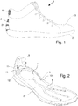
Figure 1 a schematic representation of a side view of an embodiment of the shoe according to the invention, -
Figure 2 a schematic view of the sole construction of the inFigure 1 shown embodiment of the shoe according to the invention, -
Figures 3A to 3C schematic views of the switching device of the inFigure 1 shown embodiment of the shoe according to the invention and -
Figure 4 a schematic view of the sole with the arrangement of a temperature and humidity sensor on the upper side of the sole facing the interior of the shoe. -
Figure 1 shows a schematic side view of a preferred embodiment of theshoe 1 according to the invention. Theshoe 1 has asole construction 2 with an upper 3 mounted thereon. Details of thesole construction 2 of theshoe 1 according to the invention are shown in FIGSFigures 2 and4th shown. Theshoe 1 has a ventilation device with the aid of which, for example, fresh air can be pumped into the interior of the shoe. For this purpose, the ventilation device comprises anair pumping device 4, which comprises a bellows which is accommodated in a cavity within the sole construction, which has anair intake opening 6 and an air exhaust opening and which can be compressed by a load from the wearer's foot and when relieving, i.e. when lifting the Expanded again. Within an air intake line opening into theair intake opening 6 and within the air intake line extending from theair pumping device 4Air supply line 5 are each arranged valves that allow the air flow through only in a desired direction. Theair pumping device 4 thus pumps the air into theair supply line 5, which is, for example, as shown in FIGFigure 2 is shown, branches within thesole construction 2 and opens into outlet openings to the shoe interior. The ventilation device is designed, for example, as it is in thepublication EP 3 318 147 A1 air pumping device 4 via the suction line and from there to pump it further via theair supply line 5 into the interior of the shoe.
Bei dem in
Die Umschaltvorrichtung 11 umfasst erfindungsgemäß ein von einem Stellmotor angetriebenes Ventilschließelement, das bei Betätigen des Stellmotors zwischen zwei Stellpositionen bewegbar ist, wobei das Ventilschließelement in einer ersten Stellposition die erste Luftansaugleitung 7 mit der Ansaugöffnung 6 der Luftpumpvorrichtung 4 verbindet und die zweite Luftansaugleitung 9 von der Ansaugöffnung 6 trennt und in einer zweiten Stellposition die zweite Luftansaugleitung 9 mit der Ansaugöffnung 6 verbindet und die erste Luftansaugleitung 7 von der Ansaugöffnung 6 trennt. Der Stellmotor wird von einer in
In der in
Der Stellmotor 14 weißt eine Welle 18 auf, die in den Innenraum des Gehäuses 13 hineinragt und auf die das Ventilschließelement 17 mit der in den
Der Stellmotor 19 ist ein Gleichstrom-Miniaturmotor, der bei einer Ausführungsform durch Umpolen der Spannungsspeisung in eine Rotation entweder in die eine oder die entgegengesetzte Richtung versetzt wird. Zum Herabsetzen der Rotationsgeschwindigkeit kann der Motor ein einfaches Miniaturgetriebe enthalten. Mittels der Steuerschaltung 12 wird der Miniaturmotor so angesteuert, dass sich die Welle 18 entweder im Uhrzeigersinn oder in entgegengesetzter Richtung dreht, so dass das auf der Welle 18 befestigte Ventilschließelement 17 verschwenkt wird, bis es in der ersten bzw. der zweiten Stellposition an einer Seitenwand der Gehäuseunterschale 13b anschlägt. Anschließend wird der Motor 14 abgeschaltet, so dass das Ventilschließelement 17 in der eingenommenen Stellposition verbleibt. In der einfachsten Ausgestaltung erfolgt die Ansteuerung des Motors 14 mit einer fest vorgegebenen Zeitdauer, die ein vollständiges Verschwenken des Ventilschließelements 17 sicherstellt. Die Leistung des Motors 14 ist dabei so dimensioniert, dass sie einerseits zum Überwinden etwaiger Reibungskräfte ausreicht, aber andererseits so gering ist, dass der Motor 14 beim Anschlagen des Ventilschließelements 17 an die Seitenwandung der Gehäuseunterschale 13B abgebremst wird. Bei einer schaltungstechnisch aufwändigeren, aber mechanisch verbesserten Ausführungsform kann die Steuerschaltung 17 eine Sensoreinrichtung zum Erfassen eines Motorstroms und/oder einer Motorspannung des Stellmotors 14 aufweisen, wobei mit Hilfe der erfassten Ströme und/oder Spannungen ein von der Motorbelastung abhängiges Signal erzeugt wird, welches das Erreichen der ersten und zweiten Stellposition durch das Ventilschließelement 17 anzeigt und in Abhängigkeit davon den Motor 14 bei Erreichen der Stellposition abschaltet. Bei anderen Ausführungsformen können im Gehäuse 13 Sensoren angeordnet sein, die das Erreichen der ersten und zweiten Stellposition durch das Ventilschließelement 17 erfassen und entsprechende Signale an die Steuerschaltung 12 übermitteln, so dass ein Abschalten des Stellmotors 14 bei Erreichen der Stellpositionen gewährleistet ist.The
Bei der bevorzugten Ausführungsform, wie sie insbesondere in den
Der erfindungsgemäße Schuh weist einen in den Figuren nicht gezeigten Energiespeicher zum Speichern der zum Betätigen des Stellmotors 14 und zum Betrieb der Steuerschaltung 12 erforderlichen Energie auf, beispielsweise eine Batterie oder einen Akkumulator. Vorzugsweise ist ferner eine Ladeschaltung zum Wieder-Aufladen des ganz oder teilweise entladenen Energiespeichers vorgesehen. Die Ladeschaltung ist vorzugsweise mit einem Energiegenerator zum Umwandeln von mechanischer in elektrische Energie gekoppelt. Die mechanische Energie wird durch Verformen oder Bewegen eines Elements des Energiegenerators während einer Laufbewegung gewonnen. Beispielsweise umfasst das Element einen Permanentmagneten und eine Spule, die mit Hilfe der Laufbewegung und einem entsprechenden Getriebe in eine Relativbewegung zueinander gebracht werden, wobei durch Induktion mechanische in elektrische Energie umgewandelt wird. Alternativ kann elektrische Energie mit Hilfe eines verformten piezoelektrischen Elements gewonnen werden. Alternativ und zusätzlich zu dem Energiegenerator, der mechanische in elektrische Energie umwandelt, kann auch ein weiterer Energiegenerator vorgesehen sein, der Wärmeenergie, beispielsweise durch Ausnutzen der Temperaturdifferenz zwischen dem Schuhinnenraum und der Umgebung des Schuhs, in elektrische Energie umwandelt.The shoe according to the invention has an energy store, not shown in the figures, for storing the energy required to operate the
Beispielsweise können in einem Schuh auch mehrere Luftpumpvorrichtungen und/oder mehrere Luftansaugleitungen mit mehreren Umschaltvorrichtungen vorgesehen sein, die parallel zueinander wirken.For example, several air pumping devices and / or several air intake lines with several switching devices, which act parallel to one another, can also be provided in a shoe.
Claims (15)
- Shoe (1) with a ventilation device,wherein the ventilation device has an air pumping apparatus (4), an air supply line (5) which transports air from the air pumping apparatus (4) into the interior of the shoe, and an air suction line which transports air into the air pumping apparatus (4),wherein the air suction line includes:a first air suction line (7) with a first intake opening (8), which is arranged on the outside of the shoe (1) to suck in fresh air,a second air suction line (9) with a second intake opening (10) which is arranged in the interior of the shoe, anda switching apparatus (11) coupling the first (7) and the second (9) air suction lines to the air pumping apparatus (4), which connects either the first (7) or the second (9) air suction line to at least one suction opening (6) of the air pumping apparatus (4),characterized in thatthe switching apparatus (11) includes a valve closing element (17) which is driven by a servomotor (14), and which is movable between two servopositions when the servomotor (14) is actuated, wherein in a first servoposition the valve closing element (17) connects the first air suction line (7) to at least one of the at least one suction openings (6) of the air pumping apparatus (4) and disconnects the second air suction line (9) from the at least one suction opening (6) of the air pumping apparatus (4), and in a second servoposition connects the second air suction line (9) to at least one of the at least one suction openings (6) of the air pumping apparatus (4) and disconnects the first air suction line (7) from the at least one suction openings (6) of the air pumping apparatus (4),wherein the servomotor (14) is connected to the valve closing element (17) via a coupling element and the servomotor (14) and the coupling element are designed such that the valve closing element (17) is held in both servopositions without any consumption of energy,wherein the valve closing element (17) is pivotable about an axis and includes a sealing surface (26), wherein the sealing surface (26) slides over a bearing surface (25) of a housing (13B) when the valve closing element (17) is pivoted, wherein a first opening (19) of the first air suction line (7) and a second opening (20) of the second suction line (9) open into the bearing surface (25), wherein in the first servoposition the valve closing element (17) closes the second opening (20) with its sealing surface (26) and leaves the first opening (19) clear, and in the second servoposition closes the first opening (19) with its sealing surface (26) and leaves the second opening (20) clear.
- Shoe (1) with a ventilation device,wherein the ventilation device has an air pumping apparatus (4), an air supply line (5) which transports air from the air pumping apparatus (4) into the interior of the shoe, and an air suction line which transports air into the air pumping apparatus (4),wherein the air suction line includes:a first air suction line (7) with a first intake opening (8), which is arranged on the outside of the shoe (1) to suck in fresh air,a second air suction line (9) with a second intake opening (10) which is arranged in the interior of the shoe, anda switching apparatus (11) coupling the first (7) and the second (9) air suction lines to the air pumping apparatus (4), which connects either the first (7) or the second (9) air suction line to at least one suction opening (6) of the air pumping apparatus (4),characterized in thatthe switching apparatus (11) includes a valve closing element (17) which is driven by a servomotor (14), and which is movable between two servopositions when the servomotor (14) is actuated, wherein in a first servoposition the valve closing element (17) connects the first air suction line (7) to at least one of the at least one suction openings (6) of the air pumping apparatus (4) and disconnects the second air suction line (9) from the at least one suction opening (6) of the air pumping apparatus (4), and in a second servoposition connects the second air suction line (9) to at least one of the at least one suction openings (6) of the air pumping apparatus (4) and disconnects the first air suction line (7) from the at least one suction opening (6) of the air pumping apparatus (4),wherein the servomotor (14) is connected to the valve closing element (17) via a coupling element and the servomotor (14) and the coupling element are designed such that the valve closing element (17) is held in both servopositions without any consumption of energy,wherein the valve closing element comprises a valve flap in the form of a plate which can be pivoted back and forth such that in the first servoposition it covers an opening in the first air suction line with its one top face, and in the second servoposition it covers an opening in the second air suction line with its opposite top face.
- Shoe (1) according to Claim 1 or 2, characterized in that the coupling element comprises a fastening of the valve closing element (17) directly on a shaft (18) of the servomotor (14).
- Shoe (1) according to any one of Claims 1-3, characterized in that the servomotor (14) is a miniature DC servomotor or a miniature stepper motor that is actuated by a control circuit (12), wherein the control circuit (12) is configured in such manner that the servomotor (14) is actuated to move the valve closing element (17) in each case until the valve closing element (17) has reached the other servoposition.
- Shoe (1) according to Claim 4, characterized in that the control circuit (12) is coupled to a sensor apparatus, which generates a sensor signal that provides notification when the valve closing element (17) reaches the first and second servopositions.
- Shoe (1) according to Claim 5, characterized in that the sensor apparatus comprises a mechanoelectrical transducer which is actuated by the valve closing element (17) or the coupling element.
- Shoe (1) according to Claim 6, characterized in that the mechanoelectrical transducer is a mechanical limit stop switch or another position sensor or a force or pressure sensor.
- Shoe (1) according to Claim 5, characterized in that the sensor apparatus comprises at least one sensor that detects a motor current and/or a motor voltage of the servomotor (14), with the aid of which a signal whose value depends on the motor load is generated, which signal indicates when the valve closing element (17) reaches the first and second servopositions.
- Shoe (1) according to Claim 4, characterized in that the control circuit (12) is configured in such manner that the servomotor (14) is actuated for moving the valve closing element (17) for a predetermined time period in each case, with the result that that the valve closing element (17) has reached the respective other servoposition before or at the end of said time period.
- Shoe (1) according to Claim 4, characterized in that the servomotor (14) is a stepper motor and that the control circuit (12) is configured such that the stepper motor is actuated for moving the valve closing element (17) in such manner that it reaches a respective predetermined rotary position in such manner that the valve closing element (17) reaches the first or second servoposition.
- Shoe (1) according to any one of Claims 1 - 10, characterized in that the second intake opening (10) is arranged in a shaft area of the shoe interior remote from the sole.
- Shoe (1) according to any one of Claims 1 - 11, characterized byan energy accumulator for storing the energy necessary for actuating the servomotor (14) and for operating the control circuit (12),a charge circuit for charging the energy accumulator andan energy generator which is coupled to the charge circuit for converting mechanical into electrical energy, wherein the mechanical energy is obtained by deformation or movement of an element of the energy generator during a running motion.
- Shoe (1) according to any one of Claims 1 - 12, characterized bya temperature sensor (23) which is coupled to a control circuit (12) of the servomotor (14) for detecting a temperature at a predetermined site in the shoe interior,wherein the control circuit (12) is configured in such manner that when it detected that a predetermined temperature has been exceeded in the shoe interior the servomotor (14) is actuated in such manner that the valve closing element (17) is moved into the first servoposition.
- Shoe (1) according to Claim 13, characterized in that the control circuit (12) is further configured in such manner that when it detected the temperature has fallen below a second predetermined temperature in the shoe interior the servomotor (14) is actuated in such manner that the valve closing element (17) is moved into the second servoposition.
- Shoe (1) according to Claim 13 or 14, characterized in that in addition a moisture sensor for detecting a moisture value at the predetermined sited in the shoe interior is coupled to the control circuit (12) of the servomotor (14), wherein the control circuit (12) is configured in such manner that the servomotor (14) is also actuated as a function of the detected moisture value.
Priority Applications (1)
| Application Number | Priority Date | Filing Date | Title |
|---|---|---|---|
| EP19174048.9A EP3738457B1 (en) | 2019-05-13 | 2019-05-13 | Shoe with a ventilation device switchable between fresh air supply and circulated air |
Applications Claiming Priority (1)
| Application Number | Priority Date | Filing Date | Title |
|---|---|---|---|
| EP19174048.9A EP3738457B1 (en) | 2019-05-13 | 2019-05-13 | Shoe with a ventilation device switchable between fresh air supply and circulated air |
Publications (2)
| Publication Number | Publication Date |
|---|---|
| EP3738457A1 EP3738457A1 (en) | 2020-11-18 |
| EP3738457B1 true EP3738457B1 (en) | 2021-11-10 |
Family
ID=66529848
Family Applications (1)
| Application Number | Title | Priority Date | Filing Date |
|---|---|---|---|
| EP19174048.9A Active EP3738457B1 (en) | 2019-05-13 | 2019-05-13 | Shoe with a ventilation device switchable between fresh air supply and circulated air |
Country Status (1)
| Country | Link |
|---|---|
| EP (1) | EP3738457B1 (en) |
Family Cites Families (4)
| Publication number | Priority date | Publication date | Assignee | Title |
|---|---|---|---|---|
| AU2658571A (en) * | 1971-03-16 | 1972-09-21 | ||
| EP3106051B1 (en) | 2015-06-15 | 2019-09-11 | ATMOS airwalk ag | Shoe with electrical venting system |
| EP3318147B1 (en) | 2016-11-04 | 2019-08-14 | ATMOS airwalk ag | Shoe with a sole construction and an air pump apparatus for blowing air into the inside of a shoe |
| CN106942826A (en) * | 2017-04-20 | 2017-07-14 | 景素玲 | It is a kind of can be with the shoes of motorized adjustment air permeable sole |
-
2019
- 2019-05-13 EP EP19174048.9A patent/EP3738457B1/en active Active
Also Published As
| Publication number | Publication date |
|---|---|
| EP3738457A1 (en) | 2020-11-18 |
Similar Documents
| Publication | Publication Date | Title |
|---|---|---|
| AT505126B1 (en) | FLAP DRIVE SYSTEM | |
| DE10314247B4 (en) | Hinge for a camera containing mobile phones and mobile phone with such a hinge | |
| EP3532689B2 (en) | Opening and closing system having an ejection apparatus for an item of furniture, and operating method for an opening and closing system | |
| EP2105151B1 (en) | Membrane pump with ventilation valve | |
| DE102004059745B4 (en) | Automatic / manual communication terminal of sliding type | |
| DE102010060735A1 (en) | Electric pump | |
| EP4344712A2 (en) | Breast pump | |
| EP1179458A2 (en) | Actuator for a lid and pedestrian protection system for vehicles | |
| DE102015214301A1 (en) | Furniture and adjusting arrangement, in particular for a backrest adjustment | |
| DE69111066T2 (en) | VALVE DEVICE. | |
| DE69605546T2 (en) | DEVICE FOR DISTRIBUTING A LIQUID, WITH A REMOTE-CONTROLLED MOTOR, IN PARTICULAR A WATER MIXING DEVICE | |
| EP0266657A2 (en) | Control device | |
| DE69114132T2 (en) | PULSATOR FOR MILKING MACHINES. | |
| DE102018114829B3 (en) | Medical implant, operating device for a medical implant, medical device and method for the electrical supply of a medical implant | |
| DE102018100371A1 (en) | Vacuum cleaning device with a filter bag and filter bag for a vacuum cleaning device | |
| EP3738457A1 (en) | Shoe with a ventilation device switchable between fresh air supply and circulated air | |
| DE102010055466A1 (en) | Futterabdeckungsbetätigungsvorrichtung, in particular for feed containers and a feeding device | |
| DE19830312B4 (en) | By a combustion and electric motor driven hybrid compressor | |
| EP3454919B1 (en) | Membrane vacuum pump | |
| EP0991877A1 (en) | Device, specially a pump | |
| EP3655685A1 (en) | Actuating unit having a safety actuating function | |
| DE102017102069A1 (en) | Flow actuator | |
| DE4416599C2 (en) | Ventilator | |
| DE102017106546A1 (en) | Oil pump with electrically adjustable displacement | |
| CH389755A (en) | Zero voltage reset device on an electromotive drive for a mechanical or hydraulic actuator |
Legal Events
| Date | Code | Title | Description |
|---|---|---|---|
| PUAI | Public reference made under article 153(3) epc to a published international application that has entered the european phase |
Free format text: ORIGINAL CODE: 0009012 |
|
| STAA | Information on the status of an ep patent application or granted ep patent |
Free format text: STATUS: THE APPLICATION HAS BEEN PUBLISHED |
|
| AK | Designated contracting states |
Kind code of ref document: A1 Designated state(s): AL AT BE BG CH CY CZ DE DK EE ES FI FR GB GR HR HU IE IS IT LI LT LU LV MC MK MT NL NO PL PT RO RS SE SI SK SM TR |
|
| AX | Request for extension of the european patent |
Extension state: BA ME |
|
| STAA | Information on the status of an ep patent application or granted ep patent |
Free format text: STATUS: REQUEST FOR EXAMINATION WAS MADE |
|
| 17P | Request for examination filed |
Effective date: 20210518 |
|
| RBV | Designated contracting states (corrected) |
Designated state(s): AL AT BE BG CH CY CZ DE DK EE ES FI FR GB GR HR HU IE IS IT LI LT LU LV MC MK MT NL NO PL PT RO RS SE SI SK SM TR |
|
| GRAP | Despatch of communication of intention to grant a patent |
Free format text: ORIGINAL CODE: EPIDOSNIGR1 |
|
| STAA | Information on the status of an ep patent application or granted ep patent |
Free format text: STATUS: GRANT OF PATENT IS INTENDED |
|
| INTG | Intention to grant announced |
Effective date: 20210719 |
|
| GRAS | Grant fee paid |
Free format text: ORIGINAL CODE: EPIDOSNIGR3 |
|
| GRAA | (expected) grant |
Free format text: ORIGINAL CODE: 0009210 |
|
| STAA | Information on the status of an ep patent application or granted ep patent |
Free format text: STATUS: THE PATENT HAS BEEN GRANTED |
|
| AK | Designated contracting states |
Kind code of ref document: B1 Designated state(s): AL AT BE BG CH CY CZ DE DK EE ES FI FR GB GR HR HU IE IS IT LI LT LU LV MC MK MT NL NO PL PT RO RS SE SI SK SM TR |
|
| REG | Reference to a national code |
Ref country code: GB Ref legal event code: FG4D Free format text: NOT ENGLISH |
|
| REG | Reference to a national code |
Ref country code: AT Ref legal event code: REF Ref document number: 1445241 Country of ref document: AT Kind code of ref document: T Effective date: 20211115 Ref country code: CH Ref legal event code: EP |
|
| REG | Reference to a national code |
Ref country code: DE Ref legal event code: R096 Ref document number: 502019002684 Country of ref document: DE |
|
| REG | Reference to a national code |
Ref country code: IE Ref legal event code: FG4D Free format text: LANGUAGE OF EP DOCUMENT: GERMAN |
|
| REG | Reference to a national code |
Ref country code: LT Ref legal event code: MG9D |
|
| REG | Reference to a national code |
Ref country code: NL Ref legal event code: MP Effective date: 20211110 |
|
| PG25 | Lapsed in a contracting state [announced via postgrant information from national office to epo] |
Ref country code: RS Free format text: LAPSE BECAUSE OF FAILURE TO SUBMIT A TRANSLATION OF THE DESCRIPTION OR TO PAY THE FEE WITHIN THE PRESCRIBED TIME-LIMIT Effective date: 20211110 Ref country code: LT Free format text: LAPSE BECAUSE OF FAILURE TO SUBMIT A TRANSLATION OF THE DESCRIPTION OR TO PAY THE FEE WITHIN THE PRESCRIBED TIME-LIMIT Effective date: 20211110 Ref country code: FI Free format text: LAPSE BECAUSE OF FAILURE TO SUBMIT A TRANSLATION OF THE DESCRIPTION OR TO PAY THE FEE WITHIN THE PRESCRIBED TIME-LIMIT Effective date: 20211110 Ref country code: BG Free format text: LAPSE BECAUSE OF FAILURE TO SUBMIT A TRANSLATION OF THE DESCRIPTION OR TO PAY THE FEE WITHIN THE PRESCRIBED TIME-LIMIT Effective date: 20220210 |
|
| PG25 | Lapsed in a contracting state [announced via postgrant information from national office to epo] |
Ref country code: IS Free format text: LAPSE BECAUSE OF FAILURE TO SUBMIT A TRANSLATION OF THE DESCRIPTION OR TO PAY THE FEE WITHIN THE PRESCRIBED TIME-LIMIT Effective date: 20220310 Ref country code: SE Free format text: LAPSE BECAUSE OF FAILURE TO SUBMIT A TRANSLATION OF THE DESCRIPTION OR TO PAY THE FEE WITHIN THE PRESCRIBED TIME-LIMIT Effective date: 20211110 Ref country code: PT Free format text: LAPSE BECAUSE OF FAILURE TO SUBMIT A TRANSLATION OF THE DESCRIPTION OR TO PAY THE FEE WITHIN THE PRESCRIBED TIME-LIMIT Effective date: 20220310 Ref country code: PL Free format text: LAPSE BECAUSE OF FAILURE TO SUBMIT A TRANSLATION OF THE DESCRIPTION OR TO PAY THE FEE WITHIN THE PRESCRIBED TIME-LIMIT Effective date: 20211110 Ref country code: NO Free format text: LAPSE BECAUSE OF FAILURE TO SUBMIT A TRANSLATION OF THE DESCRIPTION OR TO PAY THE FEE WITHIN THE PRESCRIBED TIME-LIMIT Effective date: 20220210 Ref country code: NL Free format text: LAPSE BECAUSE OF FAILURE TO SUBMIT A TRANSLATION OF THE DESCRIPTION OR TO PAY THE FEE WITHIN THE PRESCRIBED TIME-LIMIT Effective date: 20211110 Ref country code: LV Free format text: LAPSE BECAUSE OF FAILURE TO SUBMIT A TRANSLATION OF THE DESCRIPTION OR TO PAY THE FEE WITHIN THE PRESCRIBED TIME-LIMIT Effective date: 20211110 Ref country code: HR Free format text: LAPSE BECAUSE OF FAILURE TO SUBMIT A TRANSLATION OF THE DESCRIPTION OR TO PAY THE FEE WITHIN THE PRESCRIBED TIME-LIMIT Effective date: 20211110 Ref country code: GR Free format text: LAPSE BECAUSE OF FAILURE TO SUBMIT A TRANSLATION OF THE DESCRIPTION OR TO PAY THE FEE WITHIN THE PRESCRIBED TIME-LIMIT Effective date: 20220211 |
|
| PG25 | Lapsed in a contracting state [announced via postgrant information from national office to epo] |
Ref country code: SM Free format text: LAPSE BECAUSE OF FAILURE TO SUBMIT A TRANSLATION OF THE DESCRIPTION OR TO PAY THE FEE WITHIN THE PRESCRIBED TIME-LIMIT Effective date: 20211110 Ref country code: SK Free format text: LAPSE BECAUSE OF FAILURE TO SUBMIT A TRANSLATION OF THE DESCRIPTION OR TO PAY THE FEE WITHIN THE PRESCRIBED TIME-LIMIT Effective date: 20211110 Ref country code: RO Free format text: LAPSE BECAUSE OF FAILURE TO SUBMIT A TRANSLATION OF THE DESCRIPTION OR TO PAY THE FEE WITHIN THE PRESCRIBED TIME-LIMIT Effective date: 20211110 Ref country code: ES Free format text: LAPSE BECAUSE OF FAILURE TO SUBMIT A TRANSLATION OF THE DESCRIPTION OR TO PAY THE FEE WITHIN THE PRESCRIBED TIME-LIMIT Effective date: 20211110 Ref country code: EE Free format text: LAPSE BECAUSE OF FAILURE TO SUBMIT A TRANSLATION OF THE DESCRIPTION OR TO PAY THE FEE WITHIN THE PRESCRIBED TIME-LIMIT Effective date: 20211110 Ref country code: DK Free format text: LAPSE BECAUSE OF FAILURE TO SUBMIT A TRANSLATION OF THE DESCRIPTION OR TO PAY THE FEE WITHIN THE PRESCRIBED TIME-LIMIT Effective date: 20211110 Ref country code: CZ Free format text: LAPSE BECAUSE OF FAILURE TO SUBMIT A TRANSLATION OF THE DESCRIPTION OR TO PAY THE FEE WITHIN THE PRESCRIBED TIME-LIMIT Effective date: 20211110 |
|
| REG | Reference to a national code |
Ref country code: DE Ref legal event code: R097 Ref document number: 502019002684 Country of ref document: DE |
|
| PLBE | No opposition filed within time limit |
Free format text: ORIGINAL CODE: 0009261 |
|
| STAA | Information on the status of an ep patent application or granted ep patent |
Free format text: STATUS: NO OPPOSITION FILED WITHIN TIME LIMIT |
|
| 26N | No opposition filed |
Effective date: 20220811 |
|
| PG25 | Lapsed in a contracting state [announced via postgrant information from national office to epo] |
Ref country code: AL Free format text: LAPSE BECAUSE OF FAILURE TO SUBMIT A TRANSLATION OF THE DESCRIPTION OR TO PAY THE FEE WITHIN THE PRESCRIBED TIME-LIMIT Effective date: 20211110 |
|
| PG25 | Lapsed in a contracting state [announced via postgrant information from national office to epo] |
Ref country code: SI Free format text: LAPSE BECAUSE OF FAILURE TO SUBMIT A TRANSLATION OF THE DESCRIPTION OR TO PAY THE FEE WITHIN THE PRESCRIBED TIME-LIMIT Effective date: 20211110 |
|
| REG | Reference to a national code |
Ref country code: CH Ref legal event code: PL |
|
| REG | Reference to a national code |
Ref country code: BE Ref legal event code: MM Effective date: 20220531 |
|
| PG25 | Lapsed in a contracting state [announced via postgrant information from national office to epo] |
Ref country code: MC Free format text: LAPSE BECAUSE OF FAILURE TO SUBMIT A TRANSLATION OF THE DESCRIPTION OR TO PAY THE FEE WITHIN THE PRESCRIBED TIME-LIMIT Effective date: 20211110 Ref country code: LU Free format text: LAPSE BECAUSE OF NON-PAYMENT OF DUE FEES Effective date: 20220513 Ref country code: LI Free format text: LAPSE BECAUSE OF NON-PAYMENT OF DUE FEES Effective date: 20220531 Ref country code: CH Free format text: LAPSE BECAUSE OF NON-PAYMENT OF DUE FEES Effective date: 20220531 |
|
| PG25 | Lapsed in a contracting state [announced via postgrant information from national office to epo] |
Ref country code: IE Free format text: LAPSE BECAUSE OF NON-PAYMENT OF DUE FEES Effective date: 20220513 |
|
| PG25 | Lapsed in a contracting state [announced via postgrant information from national office to epo] |
Ref country code: IT Free format text: LAPSE BECAUSE OF FAILURE TO SUBMIT A TRANSLATION OF THE DESCRIPTION OR TO PAY THE FEE WITHIN THE PRESCRIBED TIME-LIMIT Effective date: 20211110 Ref country code: BE Free format text: LAPSE BECAUSE OF NON-PAYMENT OF DUE FEES Effective date: 20220531 |
|
| PG25 | Lapsed in a contracting state [announced via postgrant information from national office to epo] |
Ref country code: MK Free format text: LAPSE BECAUSE OF FAILURE TO SUBMIT A TRANSLATION OF THE DESCRIPTION OR TO PAY THE FEE WITHIN THE PRESCRIBED TIME-LIMIT Effective date: 20211110 Ref country code: CY Free format text: LAPSE BECAUSE OF FAILURE TO SUBMIT A TRANSLATION OF THE DESCRIPTION OR TO PAY THE FEE WITHIN THE PRESCRIBED TIME-LIMIT Effective date: 20211110 |
|
| PG25 | Lapsed in a contracting state [announced via postgrant information from national office to epo] |
Ref country code: HU Free format text: LAPSE BECAUSE OF FAILURE TO SUBMIT A TRANSLATION OF THE DESCRIPTION OR TO PAY THE FEE WITHIN THE PRESCRIBED TIME-LIMIT; INVALID AB INITIO Effective date: 20190513 |
|
| PG25 | Lapsed in a contracting state [announced via postgrant information from national office to epo] |
Ref country code: TR Free format text: LAPSE BECAUSE OF FAILURE TO SUBMIT A TRANSLATION OF THE DESCRIPTION OR TO PAY THE FEE WITHIN THE PRESCRIBED TIME-LIMIT Effective date: 20211110 |
|
| PG25 | Lapsed in a contracting state [announced via postgrant information from national office to epo] |
Ref country code: MT Free format text: LAPSE BECAUSE OF FAILURE TO SUBMIT A TRANSLATION OF THE DESCRIPTION OR TO PAY THE FEE WITHIN THE PRESCRIBED TIME-LIMIT Effective date: 20211110 |
|
| PGFP | Annual fee paid to national office [announced via postgrant information from national office to epo] |
Ref country code: DE Payment date: 20250531 Year of fee payment: 7 |
|
| PGFP | Annual fee paid to national office [announced via postgrant information from national office to epo] |
Ref country code: GB Payment date: 20250527 Year of fee payment: 7 |
|
| REG | Reference to a national code |
Ref country code: AT Ref legal event code: MM01 Ref document number: 1445241 Country of ref document: AT Kind code of ref document: T Effective date: 20240513 |
|
| PGFP | Annual fee paid to national office [announced via postgrant information from national office to epo] |
Ref country code: FR Payment date: 20250528 Year of fee payment: 7 |
|
| PG25 | Lapsed in a contracting state [announced via postgrant information from national office to epo] |
Ref country code: AT Free format text: LAPSE BECAUSE OF NON-PAYMENT OF DUE FEES Effective date: 20240513 |
|
| PGFP | Annual fee paid to national office [announced via postgrant information from national office to epo] |
Ref country code: AT Payment date: 20260410 Year of fee payment: 5 |