EP3739121A1 - Plaque de revêtement et rail de montage pour plaque de revêtement ainsi que système de pose pourvu de plaque de revêtement et rail de montage - Google Patents
Plaque de revêtement et rail de montage pour plaque de revêtement ainsi que système de pose pourvu de plaque de revêtement et rail de montage Download PDFInfo
- Publication number
- EP3739121A1 EP3739121A1 EP19175166.8A EP19175166A EP3739121A1 EP 3739121 A1 EP3739121 A1 EP 3739121A1 EP 19175166 A EP19175166 A EP 19175166A EP 3739121 A1 EP3739121 A1 EP 3739121A1
- Authority
- EP
- European Patent Office
- Prior art keywords
- installation rail
- covering plate
- plate
- receiving
- base body
- Prior art date
- Legal status (The legal status is an assumption and is not a legal conclusion. Google has not performed a legal analysis and makes no representation as to the accuracy of the status listed.)
- Withdrawn
Links
Images


Classifications
-
- E—FIXED CONSTRUCTIONS
- E01—CONSTRUCTION OF ROADS, RAILWAYS, OR BRIDGES
- E01C—CONSTRUCTION OF, OR SURFACES FOR, ROADS, SPORTS GROUNDS, OR THE LIKE; MACHINES OR AUXILIARY TOOLS FOR CONSTRUCTION OR REPAIR
- E01C17/00—Pavement lights, i.e. translucent constructions forming part of the surface
-
- G—PHYSICS
- G09—EDUCATION; CRYPTOGRAPHY; DISPLAY; ADVERTISING; SEALS
- G09F—DISPLAYING; ADVERTISING; SIGNS; LABELS OR NAME-PLATES; SEALS
- G09F19/00—Advertising or display means not otherwise provided for
- G09F19/22—Advertising or display means on roads, walls or similar surfaces, e.g. illuminated
-
- E—FIXED CONSTRUCTIONS
- E04—BUILDING
- E04F—FINISHING WORK ON BUILDINGS, e.g. STAIRS, FLOORS
- E04F13/00—Coverings or linings, e.g. for walls or ceilings
- E04F13/07—Coverings or linings, e.g. for walls or ceilings composed of covering or lining elements; Sub-structures therefor; Fastening means therefor
- E04F13/08—Coverings or linings, e.g. for walls or ceilings composed of covering or lining elements; Sub-structures therefor; Fastening means therefor composed of a plurality of similar covering or lining elements
- E04F13/0862—Coverings or linings, e.g. for walls or ceilings composed of covering or lining elements; Sub-structures therefor; Fastening means therefor composed of a plurality of similar covering or lining elements composed of a number of elements which are identical or not, e.g. carried by a common web, support plate or grid
-
- E—FIXED CONSTRUCTIONS
- E04—BUILDING
- E04F—FINISHING WORK ON BUILDINGS, e.g. STAIRS, FLOORS
- E04F13/00—Coverings or linings, e.g. for walls or ceilings
- E04F13/07—Coverings or linings, e.g. for walls or ceilings composed of covering or lining elements; Sub-structures therefor; Fastening means therefor
- E04F13/08—Coverings or linings, e.g. for walls or ceilings composed of covering or lining elements; Sub-structures therefor; Fastening means therefor composed of a plurality of similar covering or lining elements
- E04F13/14—Coverings or linings, e.g. for walls or ceilings composed of covering or lining elements; Sub-structures therefor; Fastening means therefor composed of a plurality of similar covering or lining elements stone or stone-like materials, e.g. ceramics concrete; of glass or with an outer layer of stone or stone-like materials or glass
-
- G—PHYSICS
- G09—EDUCATION; CRYPTOGRAPHY; DISPLAY; ADVERTISING; SEALS
- G09F—DISPLAYING; ADVERTISING; SIGNS; LABELS OR NAME-PLATES; SEALS
- G09F13/00—Illuminated signs; Luminous advertising
- G09F13/04—Signs, boards or panels, illuminated from behind the insignia
- G09F13/06—Signs, boards or panels, illuminated from behind the insignia using individual cut-out symbols or cut-out silhouettes, e.g. perforated signs
-
- E—FIXED CONSTRUCTIONS
- E04—BUILDING
- E04F—FINISHING WORK ON BUILDINGS, e.g. STAIRS, FLOORS
- E04F2290/00—Specially adapted covering, lining or flooring elements not otherwise provided for
- E04F2290/02—Specially adapted covering, lining or flooring elements not otherwise provided for for accommodating service installations or utility lines, e.g. heating conduits, electrical lines, lighting devices or service outlets
- E04F2290/026—Specially adapted covering, lining or flooring elements not otherwise provided for for accommodating service installations or utility lines, e.g. heating conduits, electrical lines, lighting devices or service outlets for lighting
Definitions
- the invention relates to a covering plate with a base body which has an upper side and an underside pointing away from the upper side.
- the invention also relates to an installation rail for installing covering panels for a surface, for example a path, a wall or a ceiling, the installation rail being essentially channel-shaped and having a receiving opening for at least one covering panel.
- the invention also relates to a laying system with at least one covering plate and at least one installation rail.
- Covering plates, installation rails for covering plates and laying systems with covering plates and installation rails are generally known. So paving plates are often used for paths to provide a surface that can be walked on and / or driven by vehicles. In particular, the upper side of the covering plate can provide the surface. A path can be, for example, a footpath, a street, a parking lot, but also a platform, an area or in an airport terminal or in a trade fair hall. Alternatively, covering panels are used to provide wall or ceiling surfaces. The surface can be outside or inside a building. Installation rails can facilitate the positioning of the paving slabs during the construction of the path and provide space below the paving slab for the installation, for example of fluid lines. In the case of laying systems, the covering panels and the installation rails can be adapted to each other and to the path to be built.
- the covering plate can also be referred to as a floor plate. If the covering plate is attached to a wall in order to provide the surface of the wall, the covering plate can also be referred to as a wall plate. If the covering plate is attached to a ceiling in order to provide the surface of the ceiling, the covering plate can also be referred to as a ceiling plate.
- informational content or orientation instructions such as texts, pictograms or arrows, are placed on surfaces upset.
- information and orientation notes cannot simply be changed, so that the notes cannot be changed flexibly.
- the invention is therefore based on the object of providing a surface that is easy to prepare or produce, with information or orientation instructions being able to be changed flexibly.
- the underside has a receiving trough for receiving a light source at least in sections.
- the main body has at least one light-permeable and at least one light-impermeable section.
- the at least one light-permeable section extends from the top to the receiving trough.
- the base body has a lateral side that connects the upper side with the lower side, with an attachment element on the lateral side for attaching the covering plate to an installation rail.
- the receiving trough can also be referred to as a receiving sink or a receiving recess.
- the shaping of the base body with the at least one light-permeable and the at least one light-impermeable section and the formation of the lateral side with the attachment element can each be advantageous individually and independently of one another.
- the invention is achieved for the installation rail mentioned at the outset in that the installation rail has a side wall adjoining the receiving opening, the side wall being provided with a counter-attachment element.
- the counter attachment element protrudes from the side wall or is formed as a recess formed in the side wall.
- the object is achieved in that the at least one covering plate is the covering plate according to the invention and the at least one installation rail is the installation rail according to the invention.
- the covering plate can easily be attached to the installation rail, wherein the counter attachment element can predetermine an installed position of the covering plate.
- a light source that backlights the section that is transparent to light can, for example, be switched on and off or its luminous color can be changed in order to change information or orientation notes easily and quickly.
- the invention can be further improved by further, in each case advantageous and, unless otherwise described, easily combinable embodiments. These further possible configurations and their advantages are discussed below.
- the attachment element is at least partially designed as a projection or recess extending parallel to the top and / or to the bottom.
- the attachment element extends completely over the lateral side along a width direction of the base body that runs parallel to the upper side and / or to the lower side.
- the covering plate has a receiving shell that forms the receiving trough and is at least partially embedded in the base body.
- the receiving tray can be dispensed with.
- the receiving trough can be shaped differently and, for example, milled into a prefabricated base body. If the base body is manufactured by casting, the receiving trough can be formed during the casting and, for example, by a casting tool.
- the covering plate has a mounting shell inserted into the receiving trough.
- the mounting shell can be pressed into the receiving recess in such a way that it is held in the receiving recess with a force fit.
- the mounting shell can also be held differently in the receiving recess and, for example, by potting or gluing or screwing his.
- the side of the mounting shell pointing into the receiving recess can be shaped complementary to the receiving recess.
- the mounting shell has at least one fastening element for fastening the illuminant and / or at least one other component.
- the other component can be an electrical or an electronic component and, for example, a circuit board equipped with electrical and / or electronic components.
- the lighting means can have a further electrical or an electronic component and / or a circuit board equipped with electrical and / or electronic components.
- the mounting shell forms a mounting recess that opens away from the top for receiving a light source at least in sections.
- the mounting shell has an end plate at its end facing the top.
- the end plate can be referred to as the bottom or the roof of the mounting shell.
- the end plate has at least one light-permeable section, which is arranged such that it at least partially or even completely overlaps the at least one light-impermeable section of the base body. Overlapping can mean that a projection of the light-permeable section of the end plate along a height direction of the covering panel and / or along a lighting direction of the built-in illuminant intersects or even penetrates the light-permeable section of the base body.
- An advantage of this configuration can be that light emitted by the lighting means can easily reach the light-permeable section of the base body.
- the covering plate has a light source, the light source and optionally the at least one other component being encapsulated in the assembly cavity.
- An advantage of this embodiment can be that the potting means that the lighting means and optionally the at least one other component are better protected from environmental influences, for example moisture or dust.
- the mounting shell and the lighting means form a light module that can be handled in one piece.
- the lighting means arranged in the mounting recess can be detachably or permanently attached to the mounting shell and, for example, encapsulated with a potting means arranged in the mounting recess.
- An advantage of this configuration can be that the light module is easier to handle and assemble, with the light source being better protected against damage and environmental influences as part of the light module, especially in the harsh environment of a construction site.
- the light source has at least one LED and, for example, a plurality of LEDs or LED groups as the light source.
- the light source can be provided with optional components on a circuit board.
- the lamp can be inserted into the mounting recess.
- the lamp and in particular its circuit board can be fastened in or on the mounting shell and, for example, on its fastening means.
- the lighting means and in particular its circuit board can be surrounded by a potting material.
- the potting material can be transparent.
- the illuminant and in particular its circuit board can be encapsulated with the potting material after it has been introduced into the mounting recess and optionally after the illuminant has been connected to external electrical or electronic components.
- the laying system can have the external electrical or electronic components.
- a cover can be provided with which the opening of the mounting recess facing away from the top of the base body can be closed. In the closed state, the cover can close in a watertight manner against the base body and / or against the mounting shell.
- the mounting shell is captive and non-destructively detachable from the receiving shell, the receiving trough and / or on attached to a section of the base body arranged outside the receiving trough.
- One advantage of this configuration can be that the mounting shell can be exchanged easily. If, for example, the illuminant is encapsulated in the mounting shell, it is possible that the illuminant can no longer be easily detached from the mounting shell. As a result, it is possible, for example, when the lamp is to be exchanged, to exchange the mounting shell with the lamp.
- the illuminant is fastened to the mounting shell, for example by means of form-fitting or force-fitting fastening elements, or by potting.
- the mounting shell and the lighting means can be connected to one another in a manageable manner.
- One advantage of these configurations can be that the facing plate is easier to assemble.
- the receiving shell has two fastening projections each extending away from the receiving trough.
- the fastening projections possibly extend in opposite directions away from the receiving trough and / or are arranged on opposite sides of the receiving shell.
- At least one of the fastening projections is channel-shaped and is formed so that it opens away from the top of the facing plate.
- the channel formed by the channel-shaped fastening projection can also be provided in the base body and in particular in its underside pointing away from its upper side, in particular when on the Receiving tray is omitted.
- the channel can open away from the top and extend from the receiving trough as far as a lateral side of the base body that connects the top and bottom.
- Multiple channels can optionally be provided. If several channels are provided, these can be arranged on different sides or on a selected side of the receiving trough.
- the at least one channel can open into the receiving trough.
- the fastening projections are at least partially embedded in the base body.
- the receiving shell has outer sides pointing away from the receiving trough. At least one of the fastening projections protrudes from the outer sides. At least one fastening element is arranged on selected ones of the outer sides. A projection of one of the fastening elements overlaps one of the fastening projections along the height direction of the base body running from the top to the bottom.
- At least one of the fastening elements has a screw receptacle for a fastening screw fastening the mounting shell.
- the base body can be provided with the screw receptacle.
- a side of the facing plate facing away from the attachment element is formed with a retaining projection.
- the holding projection is arranged at a distance from the top. According to one possible embodiment, the holding projection is aligned with the underside of the facing plate.
- the covering plate and, for example, its base body have a channel-shaped cable groove which opens away from the top and leads from the receiving trough to one of the lateral sides.
- the cable groove can be formed separately or through the above-mentioned channel.
- the installation rail has a base contacting the side wall and at least one support projection extending from the base in the direction of the receiving opening.
- the support projection is arranged at a distance from the counter attachment element.
- the side wall projects beyond the at least one support projection from the facing plate in the direction of the receiving opening.
- the installation rail has two side walls.
- the receiving opening is arranged between the side walls.
- the at least one support projection is arranged closer to one of the side walls than to the other of the side walls.
- the at least one support projection is arranged further away from the side wall having the counter-mounting element than from the other side wall.
- the at least one support projection adjoins one of the side walls.
- the side wall to which the at least one support projection adjoins forms one side of the support projection.
- the at least one support projection has at least one cavity extending along a longitudinal direction of the installation rail.
- the at least one support projection has two cavities extending along a longitudinal direction of the installation rail.
- the cavities are separated from one another at least in sections by an inner wall.
- the cavities are arranged one behind the other perpendicularly or parallel to the receiving opening.
- the at least one support projection has at least one interruption along its longitudinal direction.
- a configuration can be that connection lines can be laid from one side of the support projection to the other side of the support projection.
- the installation rail has a plurality of support projections.
- the support projections are arranged at a distance from one another transversely to a longitudinal direction of the installation rail.
- the facing plate adjoins the side wall of the built-in rail that has the counter-mounting element.
- a cover plate can be arranged as the other plate between the covering plate and the other side wall.
- the cover plate can be an ordinary covering plate with the same or different dimensions as the covering plate according to the invention, but without light-permeable sections, or a further covering plate according to the invention.
- the cover plate rests on the at least one support projection.
- the cover plate rests on the holding projection and / or on at least one of the support projections.
- the cover plate is attached to the installation rail.
- the cover plate is attached to the at least one support projection.
- the laying system has a fastening element which fasten the cover plate to the installation rail.
- the fastening element is arranged closer to a side adjoining the covering plate than on a side facing away from the covering plate.
- the channel-shaped cable groove opens in the direction of the at least one support projection and, for example, in the direction of its interruption.
- a lighting means is arranged in the receiving recess. Connecting cables leading to the lamp run through the cable groove.
- connection lines extend through the interruption of the at least one support projection.
- the covering plate has several lighting means and several light-permeable sections.
- the covering plate has a light source for each light-permeable section.
- the multiple lighting means can have a common circuit board and / or can be switched separately.
- An advantage of this configuration can be that the light-permeable sections can be selectively backlit.
- the laying system has a control system for manual or automatic control of the at least one lighting means.
- control system is designed to operate selected or all lighting means together and / or individual lighting means separately.
- the covering plate has light-permeable sections which can be selectively backlit by at least one illuminant in order to make the indications on the surface of the covering plate visible.
- the invention can solve the problem by a method for providing information on a surface, in particular a path, a wall or a ceiling, in which selected light-permeable sections of the floor can be selectively illuminated from below in order to display information or orientation aids, for example as text, symbols or pictograms, in a visible and flexible manner.
- information or orientation aids for example as text, symbols or pictograms, in a visible and flexible manner.
- An advantage of this solution can be that notes or orientation aids can be changed flexibly.
- individual or several translucent sections can be selectively backlit.
- the floor can be designed as a platform, that is, as a footpath.
- the floor can also be a surface of a driveway, for example a street or a parking lot.
- the laying system according to the invention can be used to carry out the method.
- the laying system can selectively backlight individual of the light-permeable sections of the covering panel or several covering panels according to the invention.
- the laying system provides information on where the doors of a train that is about to stop at the platform will be located. For example, areas of the floor where the doors of the train will be located are backlit. Sections where no train doors are expected may not or may be different be backlit. In order to guide people to the entry areas where the doors are expected, sections of the floor and / or sections of the floor adjoining the entry areas can be backlit in a substantially arrow-shaped manner.
- the notes can be position notes that mark the door positions of an expected train on the platform, for example.
- the train position can be displayed as an indication, for example if the train is shorter than the platform and / or trains of different lengths stop at a platform.
- information on the utilization of individual wagons or compartments of an expected train or a train that is already standing on the platform could be displayed. Warning notices could also be displayed, for example when a train is about to pass through the platform.
- the indications can be designed, for example, as arrows or as moving or changing and, for example, dynamic patterns which point to the expected stopping position of the train or the train doors.
- the information can be designed as different colors, for example, which represent the capacity utilization of a wagon or compartment, for example red for full, yellow for moderately full and green for empty, or colors which symbolize compartments of the first and second class.
- a warning can be given, for example, by at least one red and optionally pulsing or flashing cross.
- warning notices can be given, for example, along the edge of a platform, for example when a train is due to pass through a station.
- the notices can also be other warning notices and, for example, simulate a pedestrian traffic light on the ground, so that selected surfaces alternately display several colors, such as red, yellow and green, or, as with a classic pedestrian traffic light, several surfaces each display one of the colors red, yellow and green.
- the information can be given as areas or, for example, as lines and / or crosses or arrows that light up statically or pulsate or flash.
- Information on the runways or parking positions to be used for an aircraft can be given on a runway.
- the distance from a target position for example the distance from an airplane or a car to its optimal parking position, can also be used as an indication are displayed. Indications of different distances can be given by different flashing frequencies.
- the selective backlighting of individual sections of the floor can be adapted to the respective circumstances.
- the boarding areas can be adapted to different trains and / or trains that stop at different positions.
- the train can communicate the positions of the train doors directly or indirectly to the laying system, for example by the train transmitting the distances between the train doors and the train, the laying system or an external system determining the stopping position of the train on the platform.
- routes to destinations other than the boarding areas can be displayed.
- routes by person can be displayed flexibly for each of the persons, for example with a color assigned to each of the persons or the routes. If there are people on one of the specified routes, this route can be backlit in the predetermined color. Other routes can be backlit differently.
- the person can, for example, carry a data carrier that can be read out by the laying system and whose data represent the person or the route and can be evaluated by the laying system.
- the routes can be, for example, routes in a city center, at a trade fair or in a parking garage or on a parking lot in order to guide vehicles to free parking spaces or to an exit, or people to their parked vehicles.
- An event can be a sensor signal, the achievement of at least a predetermined weight, a predetermined number of people, the triggering of a light sensor, the triggering of a temperature sensor, etc. Sensor signals the Reaching different thresholds can result in different clues.
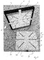
- Figure 1 shows an embodiment of the facing plate 1 according to the invention schematically in a top or plan view.
- the facing plate 1 has a base body 2 with an upper side 3 pointing out of the plane of the drawing and an underside 4 opposite the upper side 3 and pointing into the plane of the drawing.
- the facing plate 1 has an essentially square shape.
- the covering plate 1 can, however, also be shaped differently and, for example, rectangular, polygonal with precisely, more or less than four corners or also round, oval or irregularly shaped.
- Lateral sides 5 - 8 of the base body 2 connect its top 3 with its bottom 4.
- the lateral sides 5 - 8 can run perpendicular to the top 3.
- at least one of the lateral sides 5-8 can form an angle with the upper side 3 which is smaller than 270 °.
- the upper side 3 of the base body 2 can provide a surface of a path, for example a walkway or driveway.
- the base body 2 has at least one light-permeable section and, in the exemplary embodiment, FIG Figure 1 a total of six light-permeable sections 9-14.
- the base body 2 can have more or less than six and for example two, three, four, five, seven, eight, nine or between ten and twenty or even more light-permeable sections.
- At least one or all of the light-permeable sections 9-14 extend from the upper side 3 through the main body 2. Preferably, one or all of the light-permeable sections 9-14 extend perpendicular to the upper side 3 through the main body 2.
- the at least one light-permeable section 9-14 can be shaped as desired and, for example, curved along the top side 3. In the embodiment of Figure 1 however, the light-permeable sections 9-14 are straight and run along imaginary rays away from their common point of intersection. The point of intersection can be arranged at a distance from selected or from all of the light-transmissive sections 9-14. In each case three of the light-permeable sections 9, 10, 11 and / or 12, 13, 14 can be arranged to run at an angle between 20 ° and 60 ° and, for example, at an angle of 45 °.
- a central light-permeable section 10, 13 can be flanked by two light-permeable sections 9, 11 or 12, 14.
- the light-permeable sections 9, 12 and / or 11, 14 can extend at an angle to one another which is between 60 ° and 120 ° and, for example, 90 °.
- connection lines 15, 16, 17 which protrude through the lateral side 6 into the covering plate 1.
- the number of connection lines can be greater or less than three, depending on the electrical or electronic requirements.
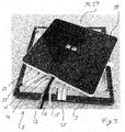
- Figure 2 shows the embodiment of Figure 1 in a schematic perspective view and with a lighting means 20.
- the covering plate 1 has a receiving trough 21 for the illuminant 20 on its underside 4.
- the receiving trough 21 opens away from the top 3.
- the light-permeable sections 9-14 extend from the top 3 to the receiving trough 21.
- the receiving trough 21 is provided by a receiving shell 22 inserted into the base body 2.
- the receiving trough 21 can, however, also be provided without the receiving shell 22 and in particular by the base body 2.
- FIG Figure 2 be shown and provided with a mounting shell 23.
- the mounting shell 23 can be used together with the lighting means 20 in the receiving trough 21.
- One side of the mounting shell 23 which, when the mounting shell 23 is inserted into the receiving cavity 21, faces into the receiving cavity 21, can be designed essentially complementary to the receiving cavity 21.
- the mounting shell 23 can have a mounting trough 24 which opens away from the top side 3 of the base body 2 and which, in the view of FIG Figure 2 is covered by an end plate 25 of the receiving shell 22.
- the lighting means 20 can be received at least in sections in the mounting recess 24.
- the end plate 25 can have at least one light-permeable section which is arranged such that it at least partially overlaps the at least one light-permeable section 9-14 of the base body 2.
- the end plate 25 of the mounting shell 23 has light-permeable sections 26 - 31, the size, position and alignment of which essentially correspond to the light-permeable sections 9 - 14 of the base body 2.
- the number of light-permeable sections 26 - 31 of the mounting shell 23 can correspond to the number of light-permeable sections 9 - 14 of the base body 2.
- the mounting shell 23 can be attached to the receiving shell 22 and / or to the base body 2 in a captive and non-destructive manner.
- the mounting shell 23 can thus have at least two fastening projections 32, 33 extending away from the mounting recess 24.
- the fastening projections 32, 33 can protrude from the receiving trough 21 when the mounting shell 23 is inserted into the receiving trough 21.
- the fastening projections 32, 33 can rest on an edge 34 of the underside 4 of the base body 2 that runs around the receiving trough 21 at least in sections.
- the fastening projections 32, 33 can extend away from the mounting recess 24 in opposite directions and / or be arranged on opposite sides of the mounting shell 23. Individual or all of the fastening projections 32, 33 can be channel-shaped and open away from the end plate 25. In the embodiment of Figure 2 however, the fastening projections 32, 33 are designed in the shape of a bar and can be arranged at a distance from the end plate 25. For example, the fastening projections 32, 33 can be aligned with a free end pointing away from the end plate 25 of a lateral side 35 of the mounting shell 23 that delimits the end plate 25 at least on one side.
- the lateral side 35 can extend perpendicular to the end plate 25 and at least partially encircle this and the mounting recess 24.
- the mounting shell 23 can have a plurality of lateral sides 35.
- At least one or all of the fastening projections 32, 33 can be embedded in the base body 2 and, for example, in its edge 34. At least one of the fastening projections 32, 33 can have a through opening 36, 37 which extends perpendicularly to the end plate 25 and is designed to receive a fastening screw.
- the mounting shell 23 is attached to the base body 2 and / or to the receiving shell 22 with the aid of the fastening screw or a plurality of fastening screws.
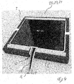
- Figure 3 shows the embodiment of the previous figures schematically in a further perspective view.
- the lighting means 20 is arranged in the mounting recess 24.
- the illuminant 20 is shown in FIG Figure 3 however, enclosed by a potting agent 38, so that the illuminant 20 in the Figure 3 is covered by the potting agent 38.
- the potting agent 38 can essentially completely fill the assembly depression 24.
- the lighting means 20 and the mounting shell 23 can be fastened to one another by the potting means 38 or otherwise and, for example, non-positively or positively. If the lighting means 20 and the mounting shell 23 are attached to one another, they can together form a lighting module 39 that can be handled in one piece.
- connection lines 15, 16, 17 can extend through the lateral side 35 or through one of the lateral sides 35 of the mounting shell 23 into the mounting recess 24.
- the lateral side 35 can have an opening for each connection line. In the exemplary embodiment shown, however, all connection lines 15, 16, 17 run through a common opening 40 on the lateral side 35.
- a closure plate 41 can be provided through which the Connecting lines 15, 16, 17 extend. The closure plate 41 can against the Connection lines 15, 16, 17 and seal against the lateral side 35 so that only insignificant amounts, if any, of the potting agent 38 can escape through the common opening 40.
- Figure 4 shows the exemplary embodiment of the previous figures, the lighting means 20 with the mounting shell 23 being inserted into the receiving trough 21 provided by the base body 2.
- the connection lines 15, 16, 17 can run through a channel-shaped cable groove 42.
- the cable groove 42 can run through the base body 2 and in particular through its edge 34 and open away from the top 3 of the base body 2.
- the cable groove 42 can extend from the receiving trough 21 to the lateral side 6 of the base body 2.
- Figure 5 shows the optional receiving shell 22 with the mounting shell 23, the receiving shell 22 providing the receiving trough 21 and the mounting shell 23 being arranged in the receiving trough 21.
- the receiving trough 21 and the mounting trough 24 open in identical directions.
- the receiving shell 22 has receiving channels 43-45, the fastening projections 32, 33 being inserted into the receiving channels 43, 44.
- the receiving channel 45 can be inserted into the cable groove 42 of the base body 2 and the connecting lines 15, 16, 17 can run through the receiving channel 45.
- the common opening 40 can be arranged between the receiving channel 45 and the mounting recess 24.
- Figure 6 shows the mounting shell 23, which can also be inserted into the receiving trough 21 of the base body 2 without the receiving shell 22.
- the mounting shell 23 can have the receiving channel 45 for receiving the connecting lines 15, 16, 17.
- FIG. 7 shows an embodiment of the installation rail 50 according to the invention in a schematic front view.
- the installation rail 50 can be designed for the installation of covering plates and in particular covering plates 1 according to the invention for a path.
- the installation rail 50 is essentially channel-shaped and has a receiving opening 51 for at least one covering plate 1.
- the installation rail 50 has a side wall 52 adjoining the receiving opening 51.
- the side wall 52 is provided with a counter-attachment element 53 for the facing plate 1.
- the counter-attachment element 53 projects from the side wall 52 in the illustrated embodiment. Alternatively this can Counter-mounting element 53 can be formed as a recess formed in the side wall 52, for example a groove.
- the installation rail 50 can have a base 54 that contacts the side wall 52. Furthermore, the installation rail 50 can have a support projection 55 that extends from the base 54 in the direction of the receiving opening.
- the support projection 55 can be arranged at a distance from the counter attachment element 53.
- the side wall 52 can project beyond the at least one support projection 55 in a height direction H pointing from the base 54 into the receiving opening 51.
- the direction can be perpendicular to the floor 54.
- the installation rail 50 can have a further side wall 56.
- the receiving opening 51 can extend between the side walls 52, 56.
- the at least one support projection 55 can be arranged closer to one of the side walls 52, 56 than to the other of the side walls 56, 52.
- the support projection 55 is arranged further away from the side wall 52 having the counter-attachment element 53 than from the other side wall 56.
- the support projection 55 or a further support projection 57 can adjoin one of the side walls 52, 56 and in particular the side wall 56 which is opposite the side wall 52 having the counter-attachment element 53.
- the side wall 56, to which the at least one support projection and in particular the further support projection 57 adjoins, can form one side of the support projection 57. Furthermore, the side wall 56 can protrude beyond the at least one supporting projection 55, 57 in the direction pointing away from the base 54.
- the installation rail 50 has several and in particular three support projections 55, 57, 58. Selected or all of the support projections 55, 57, 58 can have at least one cavity extending along a longitudinal direction L of the installation rail 50.
- the longitudinal direction L extends in the Figure 1 perpendicular to the plane of the drawing.
- the installation rail 50 extends in the longitudinal direction L and can have a cross-section that is essentially constant along the longitudinal direction L transversely to the longitudinal direction L.
- the installation rail 50 can be designed as an explosive body along its longitudinal direction L.
- the supporting projections 55, 57, 58 can be arranged at a distance from one another.
- the at least one support projection 55 or selected one or all support projections 55, 57, 58 can have at least one or even two cavities 59-62 extending along the longitudinal direction L of the installation rail 50. If the respective support projection 55, 57, 57 has two cavities 61, 62, these can be separated from one another at least in sections by an inner wall 63 of the support projection 55. In the embodiment of Figure 7 the cavities 61, 62 are arranged one behind the other perpendicular to the receiving opening 51 and / or to the bottom 54.
- the built-in rail 50 can have at least one spacer 64 on an underside 63 of the base 54 pointing away from the receiving opening 51. If the installation rail 50 has a plurality of spacers 64, these can be arranged transversely to the longitudinal direction L and, for example, spaced apart from one another in the width direction B. For example, one spacer 64 can each be aligned perpendicular to the bottom 54 with one of the side walls 52, 56, that is to say arranged in the height direction H directly in front of the respective side wall 52, 56. Additionally or alternatively, a spacer 64 or a plurality of spacers 64 can be arranged between the side walls 52, 56.
- the spacers 64 can be essentially T-shaped, wherein the transverse line can be arranged at the end of the spacer 64 pointing away from the top side 54.
- the spacer 64 can also be designed to serve as a surface enlargement and / or additional anchoring point, for example as an undercut, for gluing and / or mounting the built-in rail 50, for example in the mortar bed.
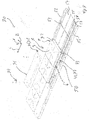
- Figure 8 shows an embodiment of the laying system 70 according to the invention schematically in a perspective view.
- the laying system 70 is shown with the built-in rail 50, with several covering plates 1 and with several cover plates 71.
- the same reference symbols are used for elements that correspond in function and / or structure to elements of the previous exemplary embodiments.
- the facing plates 1 are arranged one behind the other along the longitudinal direction L.
- the facing plates 1 In the width direction B of the built-in rail 50 running transversely to the longitudinal direction L the facing plates 1 can be placed on the counter attachment element 53.
- the covering plates 1 In order to prevent the covering plates 1 from being removed from the installation rail 50 in the height direction H running transversely to the longitudinal direction L and to the width direction B, the covering plates 1 have an attachment element 72 on the lateral side 8, which can be opposite the lateral side 6 on.
- the attachment element 72 can be shaped at least partially complementary to the counter attachment element 53 and secure the position of the respective facing plate 1 in a form-fitting manner.
- the illustrated embodiment is the attachment element 72 as a parallel to the top 3 and / or to in the Figure 8 Not visible underside 4 extending recess formed in the lateral side 8.
- the recess can be designed as a groove.
- the attachment element 72 and the counter attachment element 53 can be shaped complementary to one another.
- a width direction of the covering plate 1 can run parallel to the longitudinal direction L of the installation rail 50.
- the attachment element 72 can extend completely over the lateral side 8 along the width direction B of the facing plate 1 running parallel to the upper side 3 and / or to the lower side 4.
- the facing plate 1 and in particular its base body 2 can be formed with a holding projection 73.
- the holding projection 73 can be arranged at a distance from the upper side 3 and, for example, in alignment with the lower side 4 of the facing plate 1.
- the facing plate 1 adjoins the side wall 52 having the counter-mounting element 53.
- the optional cover plate 71 can be arranged between the facing plate 1 and the side wall 56, which is opposite the side wall 52 having the counter-attachment element 53.
- the cover plate 71 can rest on the at least one support projection, on selected ones of the support projections or on all of the support projections 55, 58, 57.
- the cover plate 71 can in particular be fastened repeatedly and detachably to the installation rail 50.
- the cover plate 71 can at least one of the support projections 55, 57, 58 be attached.
- the support projection 58, to which the cover plate 71 is fastened can have a fastening element, for example a screw receptacle, the cover plate 71 being fastened to the holding element and thus to the installation rail 50 with the aid of a counter-fastening element 74, for example a screw.
- the cover plate 71 can have, on its lateral side 75 facing the facing plate 1, an opposing retaining projection 76, which is arranged in the height direction H of the facing plate 1 behind the retaining projection 73 and, together with the opposing attachment element 53, enables the facing plate 1 to be unintentionally removed from the installation rail 50 prevented.
- the height direction of the covering plate 1 can run parallel to the height direction H of the mounting rail 50 when the covering plate is inserted and can extend from the bottom 4 to the top 3 of the covering plate 1.
- the holding projection 73 and the counter-holding projection 75 thus overlap in the height direction H.
- overlap means that a projection of an element in said direction overlaps the other element.
- the holding projection 73 and the counter-holding projection 76 can contact one another or be spaced apart from one another when the covering plate 1 and the cover plate 71 are arranged in the installation rail 50.
- At least the support projection 55 arranged closest to the facing plate 1 or adjacent to its lateral side 6 can have at least one interruption 77 along the longitudinal direction L.
- the interruption 77 can overlap the cable groove 42 of a covering plate 1 inserted into the installation rail 50 and / or be in alignment therewith.
- the cable groove 42 can therefore open away from the side wall 52 and / or towards the support body 55 or towards its interruption 77.
- the support projection 55 can have several interruptions 77, which are spaced from one another along the longitudinal direction L of the installation rail 50 such that the cable grooves 42 of all or selected ones of the covering panels 1 are each aligned with one of the interruptions 77 or overlap them.
- the connecting lines 15, 16, 17 can extend through the cable groove 52 and the interruption 77 and between the at least one Support projection 55 and the side wall 56 or between the support projection 55 and one of the support projections 57, 58 extend.
- Figure 9 shows the embodiment of Figure 8 in a schematic sectional illustration, the cutting plane being spanned by the width direction B and the height direction H.
- the longitudinal direction L points into the plane of the drawing.
- FIG. 9 shows Figure 9 that the cavities 61, 62 in contrast to the embodiment of Figure 7 can also be arranged one behind the other along the width direction B.
- the inner wall 63 can thus extend along the height direction H and the longitudinal direction L.
- At least one support rail 78, 79, 80 can be arranged on the floor 54 of the built-in rail 50, wherein the at least one support rail 78, 79, 80 can project beyond the floor 54 in the height direction H and extend along the longitudinal direction L. In the vertical direction H, the at least one support rail 78, 79, 80 can be protruded from the at least one support projection 55, 57, 58.
- the covering plate 1 and in particular the edge 34 of the base body 2 can rest on the at least one support rail 78, 79, 80 when the covering plate 1 is inserted into the installation rail 50.
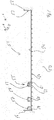
- Figure 10 shows the embodiment of Figures 8 and 9 in a schematic perspective view and with connection lines 15, 16, 17 shown schematically.
- Connection lines 15, 16, 17 running directly to one of the facing panels 1 extend in the illustrated embodiment from the respective facing panel 1 between the support projection 55 having the interruptions 77 and the projection 55 as seen the facing plate 1 following support projection 58.
- a first channel 81 extends for the connection lines 15, 16, 17.
- the connection lines 15, 16, 17 can run to a distributor 83, for which the support projections 57, 58 can have an interruption.
- Lines running between a plurality of distributors 83 or lines 84 running from the distributor 83 to a control system can extend through a further channel 82, wherein the channel 82 can be arranged between the support projections 57, 58.
- the lines 15, 16, 17 and / or the distributor 83 can be part of a control system of the laying system 70.
- Figure 11 illustrates a possible embodiment of a method for providing information on a floor, in particular a path, in which selected sections of the floor are selectively illuminated from below.
- the floor 100 is shown as a platform, that is to say as a footpath.
- the floor 100 can also be a surface of a driveway, for example a street or a parking lot.
- the laying system 70 can be used to carry out the method.
- the laying system 70 can selectively backlight selected transparent sections 9-14 of all or selected covering panels 1.
- the laying system 70 in the embodiment of FIG Figure 11 Indications as to where the doors of a train 101 that is about to stop at the platform will be.
- the train 101 is in the Figure 11 already shown to explain the exemplary method.
- the information given by the laying system 70 can of course also be displayed by the laying system 70 when the train 101 stops at the platform.
- light-permeable sections 9-14 are backlit in areas of the floor 100 on which the doors of the train 101 are or will be located. Light-permeable sections 9-14 in areas where no train doors are expected can not be backlit or be backlit in a different way. In order to lead people to the entry areas where the doors are expected, light-permeable sections 9, 11 or 12, 14 of the covering panels 1 can be located in areas that are spaced apart from the train doors Entrance areas and / or adjoining the entrance areas are essentially backlit in the shape of an arrow.
- the selective backlighting of individual light-permeable sections of the floor 100 can be adapted to the respective circumstances.
- the boarding areas can be adapted to different trains and / or trains that stop at different positions.
- the train 101 can communicate the position of the train doors directly or indirectly to the laying system 70, for example by the train 101 transmitting the distances between the train doors and the train 101, the laying system 70 or an external system determining the position of the train 101 on the platform.
Landscapes
- Engineering & Computer Science (AREA)
- Architecture (AREA)
- Civil Engineering (AREA)
- Structural Engineering (AREA)
- General Physics & Mathematics (AREA)
- Physics & Mathematics (AREA)
- Theoretical Computer Science (AREA)
- Accounting & Taxation (AREA)
- Business, Economics & Management (AREA)
- Marketing (AREA)
- Chemical & Material Sciences (AREA)
- Ceramic Engineering (AREA)
- Non-Portable Lighting Devices Or Systems Thereof (AREA)
- Installation Of Indoor Wiring (AREA)
- Finishing Walls (AREA)
- Arrangement Of Elements, Cooling, Sealing, Or The Like Of Lighting Devices (AREA)
Priority Applications (5)
| Application Number | Priority Date | Filing Date | Title |
|---|---|---|---|
| EP19175166.8A EP3739121A1 (fr) | 2019-05-17 | 2019-05-17 | Plaque de revêtement et rail de montage pour plaque de revêtement ainsi que système de pose pourvu de plaque de revêtement et rail de montage |
| PL20732483.1T PL3969661T3 (pl) | 2019-05-17 | 2020-05-14 | Płyta nawierzchniowa |
| PCT/EP2020/025221 WO2020233834A2 (fr) | 2019-05-17 | 2020-05-14 | Plaque de revêtement et rail d'encastrement pour la plaque de revêtement ainsi que système de pose pourvu de plaque de revêtement et de rail d'encastrement |
| ES20732483T ES3055967T3 (en) | 2019-05-17 | 2020-05-14 | Floor plate |
| EP20732483.1A EP3969661B1 (fr) | 2019-05-17 | 2020-05-14 | Plaque de revêtement |
Applications Claiming Priority (1)
| Application Number | Priority Date | Filing Date | Title |
|---|---|---|---|
| EP19175166.8A EP3739121A1 (fr) | 2019-05-17 | 2019-05-17 | Plaque de revêtement et rail de montage pour plaque de revêtement ainsi que système de pose pourvu de plaque de revêtement et rail de montage |
Publications (1)
| Publication Number | Publication Date |
|---|---|
| EP3739121A1 true EP3739121A1 (fr) | 2020-11-18 |
Family
ID=66589461
Family Applications (2)
| Application Number | Title | Priority Date | Filing Date |
|---|---|---|---|
| EP19175166.8A Withdrawn EP3739121A1 (fr) | 2019-05-17 | 2019-05-17 | Plaque de revêtement et rail de montage pour plaque de revêtement ainsi que système de pose pourvu de plaque de revêtement et rail de montage |
| EP20732483.1A Active EP3969661B1 (fr) | 2019-05-17 | 2020-05-14 | Plaque de revêtement |
Family Applications After (1)
| Application Number | Title | Priority Date | Filing Date |
|---|---|---|---|
| EP20732483.1A Active EP3969661B1 (fr) | 2019-05-17 | 2020-05-14 | Plaque de revêtement |
Country Status (4)
| Country | Link |
|---|---|
| EP (2) | EP3739121A1 (fr) |
| ES (1) | ES3055967T3 (fr) |
| PL (1) | PL3969661T3 (fr) |
| WO (1) | WO2020233834A2 (fr) |
Citations (7)
| Publication number | Priority date | Publication date | Assignee | Title |
|---|---|---|---|---|
| US4907361A (en) * | 1987-02-18 | 1990-03-13 | Villard Jean Pierre | Luminous panel for advertising on the ground |
| DE20102832U1 (de) * | 2001-02-17 | 2001-05-10 | Hess Form & Licht Gmbh & Co | Bodenleuchte für begehbare und/oder befahrbare Flächen |
| US7021786B1 (en) * | 2002-03-04 | 2006-04-04 | Sandor Sr Frederick J | Illuminated glass deck light panel and method of installation |
| DE102008018391A1 (de) * | 2008-04-11 | 2009-10-15 | Osram Gesellschaft mit beschränkter Haftung | Verfahren und Vorrichtung zum Beleuchten einer Haltestelle für ein Transportmittel |
| WO2010000921A1 (fr) * | 2008-06-09 | 2010-01-07 | Marimils Oy | Procédé et agencement de signalisation, guidage et alerte de passagers |
| US20130279160A1 (en) * | 2012-04-24 | 2013-10-24 | Belwith Products, Llc | LED Decorative Illuminated Trim System |
| US20170248302A1 (en) * | 2014-09-25 | 2017-08-31 | Tarkett Gdl S.A. | Backlit Floor Construction |
Family Cites Families (4)
| Publication number | Priority date | Publication date | Assignee | Title |
|---|---|---|---|---|
| DE19627856A1 (de) * | 1996-07-11 | 1998-01-15 | Happich Fahrzeug & Ind Teile | Beleuchtungsleiste und Verfahren zur Herstellung |
| DE29913554U1 (de) * | 1999-08-03 | 2000-02-10 | m-e micro-electric Vertrieb von Kommunications- und Sicherungsgeräten GmbH, 26135 Oldenburg | Leuchte mit einem Leuchtengehäuse und mit wenigstens einem Leuchtschirm |
| NZ603888A (en) * | 2010-07-30 | 2014-12-24 | Networked Infrastructure Nat Architecture Pty Ltd | A modular ducting section adapted for laying end-to- end and side by side forming a networked utilities ducting system and rain and run-off water management system |
| RO129304B1 (ro) * | 2013-08-06 | 2017-08-30 | Iulius Liviu Rusu | Trotuar arhitectural modular |
-
2019
- 2019-05-17 EP EP19175166.8A patent/EP3739121A1/fr not_active Withdrawn
-
2020
- 2020-05-14 PL PL20732483.1T patent/PL3969661T3/pl unknown
- 2020-05-14 WO PCT/EP2020/025221 patent/WO2020233834A2/fr not_active Ceased
- 2020-05-14 ES ES20732483T patent/ES3055967T3/es active Active
- 2020-05-14 EP EP20732483.1A patent/EP3969661B1/fr active Active
Patent Citations (7)
| Publication number | Priority date | Publication date | Assignee | Title |
|---|---|---|---|---|
| US4907361A (en) * | 1987-02-18 | 1990-03-13 | Villard Jean Pierre | Luminous panel for advertising on the ground |
| DE20102832U1 (de) * | 2001-02-17 | 2001-05-10 | Hess Form & Licht Gmbh & Co | Bodenleuchte für begehbare und/oder befahrbare Flächen |
| US7021786B1 (en) * | 2002-03-04 | 2006-04-04 | Sandor Sr Frederick J | Illuminated glass deck light panel and method of installation |
| DE102008018391A1 (de) * | 2008-04-11 | 2009-10-15 | Osram Gesellschaft mit beschränkter Haftung | Verfahren und Vorrichtung zum Beleuchten einer Haltestelle für ein Transportmittel |
| WO2010000921A1 (fr) * | 2008-06-09 | 2010-01-07 | Marimils Oy | Procédé et agencement de signalisation, guidage et alerte de passagers |
| US20130279160A1 (en) * | 2012-04-24 | 2013-10-24 | Belwith Products, Llc | LED Decorative Illuminated Trim System |
| US20170248302A1 (en) * | 2014-09-25 | 2017-08-31 | Tarkett Gdl S.A. | Backlit Floor Construction |
Also Published As
| Publication number | Publication date |
|---|---|
| PL3969661T3 (pl) | 2026-02-09 |
| EP3969661B1 (fr) | 2025-09-10 |
| WO2020233834A2 (fr) | 2020-11-26 |
| EP3969661C0 (fr) | 2025-09-10 |
| ES3055967T3 (en) | 2026-02-17 |
| WO2020233834A3 (fr) | 2021-01-28 |
| EP3969661A2 (fr) | 2022-03-23 |
Similar Documents
| Publication | Publication Date | Title |
|---|---|---|
| EP2049734B1 (fr) | Installation routière | |
| WO1997039204A1 (fr) | Module de construction et systeme de modules de construction pour la realisation de constructions plates, en particulier de murs | |
| DE3825446A1 (de) | Fahrspur-, gehwegs- oder baustellenbegrenzungselement | |
| WO2010083798A1 (fr) | Système de conteneurs modulaire | |
| EP3969661B1 (fr) | Plaque de revêtement | |
| DE102004035756B4 (de) | Wegbeleuchtung | |
| DE3426119A1 (de) | Bauteilsatz zur erstellung von vorzugsweise eingeschossigen baukoerpern | |
| DE19838604B4 (de) | Schilderbrücke zum Aufhängen von Verkehrszeichen oberhalb von Fahrbahnen eines Verkehrsweges | |
| DE19500176A1 (de) | Nachrüstbare Markierungsvorrichtung | |
| DE202011108029U1 (de) | Leuchtpflasterstein | |
| DE8706087U1 (de) | Wegeschutz-, Absperr- bzw. Leiteinrichtung | |
| EP3809036A1 (fr) | Dispositif modulaire d'éclairage de tunnel | |
| DE29608412U1 (de) | Flurcontainer | |
| EP1153878A2 (fr) | Dispositif de commande pour une plate-forme de levage | |
| DE102015117946A1 (de) | Deckenplatte für einen Systemparkplatz und Systemparkplatz | |
| EP0631022A2 (fr) | Elément tridimensionnel pour la construction d'ouvrages et procédé pour sa fabrication | |
| EP1637656A1 (fr) | Arrangement pour l'integration de diodes électroluminescentes dans des surfaces à marquer, de préférence des surfaces d'ouvrage | |
| DE3808259A1 (de) | Aus vorgefertigten stahlbeton-teilen zusammensetzbares gebaeude | |
| DE2527754A1 (de) | Strassenmarkierungsnagel | |
| DE2753290C2 (de) | Doppelstockgaragenanlage aus jeweils zwei transportablen Stahlbetoneinzelgaragen | |
| DE2535826C3 (de) | Bauelement fur einen dem Schutz von Personen im Bereich von Baustellen dienenden Fußgängertunnel | |
| DE8408131U1 (de) | Transportable garage | |
| DE3308556C2 (fr) | ||
| DE8906438U1 (de) | Passive Schutzeinrichtung für Verkehrswege, insbesondere Leitschwelle | |
| AT520870B1 (de) | Modulare Abdeckung für Lichtschächte, mit der Möglichkeit unterschiedliche Designs darzustellen |
Legal Events
| Date | Code | Title | Description |
|---|---|---|---|
| PUAI | Public reference made under article 153(3) epc to a published international application that has entered the european phase |
Free format text: ORIGINAL CODE: 0009012 |
|
| STAA | Information on the status of an ep patent application or granted ep patent |
Free format text: STATUS: THE APPLICATION HAS BEEN PUBLISHED |
|
| AK | Designated contracting states |
Kind code of ref document: A1 Designated state(s): AL AT BE BG CH CY CZ DE DK EE ES FI FR GB GR HR HU IE IS IT LI LT LU LV MC MK MT NL NO PL PT RO RS SE SI SK SM TR |
|
| AX | Request for extension of the european patent |
Extension state: BA ME |
|
| STAA | Information on the status of an ep patent application or granted ep patent |
Free format text: STATUS: REQUEST FOR EXAMINATION WAS MADE |
|
| 17P | Request for examination filed |
Effective date: 20210423 |
|
| RBV | Designated contracting states (corrected) |
Designated state(s): AL AT BE BG CH CY CZ DE DK EE ES FI FR GB GR HR HU IE IS IT LI LT LU LV MC MK MT NL NO PL PT RO RS SE SI SK SM TR |
|
| STAA | Information on the status of an ep patent application or granted ep patent |
Free format text: STATUS: EXAMINATION IS IN PROGRESS |
|
| 17Q | First examination report despatched |
Effective date: 20220303 |
|
| STAA | Information on the status of an ep patent application or granted ep patent |
Free format text: STATUS: THE APPLICATION IS DEEMED TO BE WITHDRAWN |
|
| 18D | Application deemed to be withdrawn |
Effective date: 20220714 |