EP3739308A1 - Vorrichtung zum erfassen mechanischer schwingungen - Google Patents
Vorrichtung zum erfassen mechanischer schwingungen Download PDFInfo
- Publication number
- EP3739308A1 EP3739308A1 EP20174873.8A EP20174873A EP3739308A1 EP 3739308 A1 EP3739308 A1 EP 3739308A1 EP 20174873 A EP20174873 A EP 20174873A EP 3739308 A1 EP3739308 A1 EP 3739308A1
- Authority
- EP
- European Patent Office
- Prior art keywords
- detection element
- vibration detection
- vibration
- housing
- power sources
- Prior art date
- Legal status (The legal status is an assumption and is not a legal conclusion. Google has not performed a legal analysis and makes no representation as to the accuracy of the status listed.)
- Granted
Links
Images

Classifications
-
- G—PHYSICS
- G01—MEASURING; TESTING
- G01H—MEASUREMENT OF MECHANICAL VIBRATIONS OR ULTRASONIC, SONIC OR INFRASONIC WAVES
- G01H1/00—Measuring characteristics of vibrations in solids by using direct conduction to the detector
-
- G—PHYSICS
- G01—MEASURING; TESTING
- G01H—MEASUREMENT OF MECHANICAL VIBRATIONS OR ULTRASONIC, SONIC OR INFRASONIC WAVES
- G01H11/00—Measuring mechanical vibrations or ultrasonic, sonic or infrasonic waves by detecting changes in electric or magnetic properties
- G01H11/06—Measuring mechanical vibrations or ultrasonic, sonic or infrasonic waves by detecting changes in electric or magnetic properties by electric means
- G01H11/08—Measuring mechanical vibrations or ultrasonic, sonic or infrasonic waves by detecting changes in electric or magnetic properties by electric means using piezoelectric devices
Definitions
- the present invention relates to a device for detecting mechanical vibrations of measurement objects, which can be attached to measurement objects for this purpose, with a housing, at least one vibration detection element and current sources, the vibration detection element and the current sources being arranged within the housing.
- Such a device is for example from US 9,921,136 B2 known.
- the vibration detection element is arranged in a lower part of the device so that it is positioned as close as possible to the measurement objects during the measurement.
- a battery provided as a power source for the device is arranged directly above the vibration detection element.
- vibration detection device is disclosed in US Pat US 8,640,545 B2 .
- the vibration detection element is arranged in a lower part of the device, while the power source is located directly above the vibration detection element of the vibration detection device.
- a vibration detection device with a vibration detection element and power sources is also from the US 9,791,310 B2 known, wherein the current sources are positioned in the vibration detection device at some distance above the vibration detection element.
- concerns DE 10 2014 205 922 A1 a module for detecting a vibration behavior of a mechanical component with a fastening component.
- the module is designed such that it can be mechanically rigidly connected to the component in order to absorb a mechanical vibration of the component.
- oscillation sensors In the case of vibration sensors, oscillation sensors or, in general, devices for detecting mechanical vibrations of measurement objects As a rule, it is desirable if these are characterized by the most linear possible detection or measurement of mechanical vibrations, with an output signal generated as a function of the detected vibrations changing linearly with the amplitude or frequency of the detected vibration.
- the device or the vibration or oscillation sensor as a whole needs to be as undisturbed as possible and the vibration detection element of the device or the sensor must be arranged as close as possible to the measurement object.
- the vibration sensor or the vibration detection element must also experience the most rigid possible coupling to the measurement object in order to be able to measure the vibration of the measurement object without interference.
- a low mass of the vibration detection element ensures that its natural resonances are outside the desired measuring range. For these reasons, devices for detecting mechanical vibrations of measurement objects have the smallest possible dimensions and have a low mass.
- intelligent vibration sensors in the context of the so-called Internet of Things (IoT) require an independent power supply because they should be operated wirelessly as possible. The power sources required for this, however, are comparatively large and heavy and therefore worsen the natural oscillation behavior of the device.
- the object of the present invention is to create a device for detecting mechanical vibrations of measurement objects with an independent power supply, the vibration behavior of which is improved compared to known devices.
- the device has at least two power sources which are arranged along at least one circle around the vibration detection element, with adjacent ones between Power sources of the same circle are each provided the same angular distances.
- the power sources arranged along a circle are distributed uniformly or symmetrically around the vibration detection element, the vibration detection element being positioned in the center of the circle on which the power sources are arranged.
- the circles are concentric to one another and the vibration detection element is located in their common center. Because of this, in the device according to the invention, the vibration detection element and the current sources are positioned along a longitudinal axis of the device essentially at the same or at a comparable height.
- each of the current sources overlaps at least partially or in sections with the vibration detection element.
- the overlapping sections are generally end sections of each power source facing the measurement object during the vibration measurement and an end section of the vibration detection element facing away from the measurement object during the vibration measurement.
- a configuration of the device is possible in which, after the device has been attached to a measurement object, surfaces of the current sources facing the measurement object and a surface of the vibration detection element facing the measurement object are equidistant from the measurement object or in which the aforementioned surfaces of the power sources and the vibration detection element align with each other in the normal direction to the longitudinal axis of the device.
- the device can also have more than two current sources, for example three, four, five, six or even more current sources, as long as they are symmetrical about the vibration detection element are spread around.
- the current sources are preferably of elongate shape or they have respective longitudinal axes which are aligned parallel to the longitudinal axis or central axis of the device.
- the specific symmetrical arrangement of the power sources around the vibration detection element in the device according to the invention means that the center of gravity of the mostly relatively heavy power sources, which are large compared to the vibration detection element, is not shifted away from the vibration detection element, but on the contrary towards it is.
- This shift in the center of gravity of the current sources influencing the volume and weight of the entire device towards the vibration detection element leads to a significant improvement in the desired vibration behavior of the device.
- this arrangement reduces tilting vibrations of the relatively high housing, which frequently occur with known vibration sensors and which are also recorded falsely by the vibration detection element of the measurement result supplied by the vibration sensor.
- the device according to the invention is characterized by a symmetrical structure that has a favorable effect on the vibration behavior of the device and thus also promotes the linear measurement behavior of the device even if the device is very small and light.
- the power sources and all other parts of the device that have to be mechanically decoupled from the vibration detection element, such as circuit boards or the housing, are not in mechanical contact with the vibration detection element and are spaced apart from it, so that measurement-falsifying vibrations of the power sources do not occur directly the vibration detection element can be transmitted.
- the power sources and the housing are free of contact with one another, i.e. the power sources and the housing are not in contact with each other or the power sources and the housing do not touch each other at any point.
- the device preferably has at least one damping body for damping vibrations of the current sources.
- This damping body can, for example, be a foam with which the power sources are sheathed or into which the power sources are plugged. Power sources encased by such a foam or plugged into such a foam body are prevented by the foam from touching the housing at any point or from coming into contact with the housing.
- vibrations of all other parts of the device that are arranged within the housing, such as circuit boards can be dampened by means of such a foam or foam body, and contact of these parts with the housing can be prevented with such a foam or foam body will.
- the damping body can fill the space in the interior of the housing around the parts arranged therein almost entirely or completely.
- the housing advantageously has a contact surface with which the device can be placed on surfaces of the measurement objects.
- This contact surface can be flat or curved.
- the contact surface can be designed in accordance with the shape of the surface of the measurement object to which the device is to be attached, in order to enable the device to be placed on the measurement object as safely and as flat as possible.
- Devices with such a contact surface particularly advantageously have at least one damping element, at least a part of the contact surface being formed by a surface of the damping element.
- the entire contact surface is particularly advantageously formed by the surface of the damping element.
- the damping element can be a rubber membrane. With such a damping element, not only can the transmission of vibrations to the housing be prevented. In addition, it can be prevented that housing vibrations are transmitted to the vibration detection element via the detour of excitation of vibrations of the measurement object.
- the vibration detection element can advantageously be connected to measurement objects, and in particular can be detachably connected to measurement objects.
- the vibration detection element can be provided with a thread which allows the vibration detection element to be detachably connected to the measurement object at a point provided for this purpose.
- a vibration detection element connected to the measurement object is not only arranged as close as possible to the measurement object, but it is also in direct contact with it and is permanently coupled to the measurement object. In such cases, the transmission of vibrations from the measurement object to the vibration detection element is direct and particularly favorable and undisturbed.
- the vibration detection element can be connected to measurement objects by means of gluing and / or by means of one or more magnets.
- At least one damping means is provided which rests on the vibration detection element.
- the damping means can therefore be arranged between the vibration detection element and the housing. As a result of the damping means, the direct transmission of housing vibrations to the vibration detection element is reduced or even prevented.
- the damping means can also be a rubber membrane.
- one and the same rubber membrane can be provided for the damping element as for the damping means, a first section of the rubber membrane fulfilling the function of the damping means and a second section the function of the damping element.
- this first section can be designed to hold the vibration detection element in the housing.
- At least one of the power sources is preferably rechargeable and / or a battery and / or a lithium battery.
- Rechargeable power sources such as accumulators are characterized by their reusability, while batteries and especially lithium batteries are more durable and more energetic than accumulators.
- all of the power sources of the device can basically be of different types. For the operation of the device, however, it is more favorable if all power sources of the device are of the same type.
- all power sources of the device can be batteries or lithium batteries, or all power sources of the device can be accumulators.
- the vibration detection element can be any desired vibration detection element.
- the vibration detection element can be a piezo element and / or a MEMS vibration sensor (MEMS: Micro-Electro-Mechanical-System).
- the device advantageously has at least one data transmission interface and / or at least one data memory and / or at least one control unit and / or at least one signal processing unit and / or at least one sensor.
- the data transmission interface can be a wired or wireless interface Transfer of data, for example act of measurement data that have been recorded by the device.
- data such as control data can be received from the device via the data transmission interface.
- a data memory can be advantageous for temporary storage of the measurement data or of received data. If, on the other hand, the device has a control unit, functions of the device can be controlled by the device itself at least partially autonomously and without external influence or externally received control data.
- oscillations or vibrations or oscillation signals detected by the oscillation detection element can already be processed or at least preprocessed in the device itself. If the device also has a sensor, it can be used to record or measure further physical variables, such as the temperature.
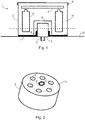
- a device for detecting mechanical vibrations or a vibration sensor 1 is in the Figure 1 seen in cross section.
- the vibration sensor 1 is shown schematically and not true to scale.
- the vibration sensor 1 has a housing 2, a vibration detection element 3, a total of six power sources 4 and a printed circuit board 5. On the circuit board there can be different in the Figure 1 Electronic components (not shown in more detail) that the vibration sensor 1 needs for its operation, such as a control unit, a data memory or a data transmission interface, can be arranged.
- the housing 2 is essentially of a hollow cylindrical shape. One side of the housing 2 is closed by a cover 6. In contrast, the side of the housing 2 facing away from the cover 6 is spanned by a rubber membrane 7. An outer surface of the rubber membrane 7 is provided as a contact surface of the housing 2, with which the housing 2 and thus the vibration sensor 1 as such can be placed or attached to surfaces of measurement objects.
- the rubber membrane 7 has an opening in its center, within which the vibration detection element 3 is arranged extending into the interior of the housing 2.
- An edge section 8 of the rubber membrane 7 surrounding the opening is turned inside the housing 2 and rests circumferentially on the vibration detection element 3.
- the power sources 4 and the printed circuit board 5 are also located inside the housing 2. With the exception of a recess 9, within which the vibration detection element 3 and the edge section 8 are arranged, the interior of the housing 2 is completely filled with a foam 10.
- a threaded section 11 is formed on the vibration detection element 3 outside the interior.
- the vibration sensor 1 for measuring oscillations or vibrations of a machine 12 is attached to the same as the measurement object, the threaded section 11 being screwed into the machine 12 at a point provided for this purpose or being screwed to the machine 12.
- Both the vibration detection element 3 comes into direct contact with a surface of the machine 12 and the outer surface of the rubber membrane 7, which forms the contact surface of the housing 2.
- a fixed connection of the housing 2 to the machine 12 is advantageous.
- the vibration sensor 1 can have magnets or an adhesive or adhesive connection can be formed between the contact surface of the housing 2 and the machine 12. After the oscillations or vibrations of the machine 12 have been measured, the vibration sensor 1 can be unscrewed from the machine 12 and removed from it.
- FIG. 2 Like in the Figure 2 can be seen showing a section through the vibration sensor 1 along the line in FIG Figure 1
- the dashed line shows the six current sources 4 of the vibration sensor 1 along one in the Figure 2 dashed circle at equal angular intervals around the vibration detection element 3 around.
- This uniform or symmetrical distribution of the current sources 4 around the vibration sensing element 3 requires in particular that the current sources 4 are not positioned above the vibration sensing element 3 but are located inside the housing 2 essentially at a comparable or the same height as the vibration sensing element 3.
- each power source 4 facing the machine 12 overlap or are aligned with an upper end section of the vibration detection element 3 facing away from the machine 12 in the normal direction to the longitudinal axis of the vibration sensor 1 or the vibration detection element 3.
- the power sources 4 are arranged relatively deep within the housing 2, so that when the vibration sensor 1 is applied to the machine 12 or to another measurement object, they are relatively close to the machine 12 or the measurement object.
- the center of gravity of the power sources 4 is also located relatively deep within the housing 2 and relatively close to the machine 12 or the measurement object.
- the height of the housing 2 is lower than with known vibration sensors, so that less high vibration amplitudes of the housing 2 can be excited and tilting vibrations of the housing 2 have less of an effect.
- the symmetrical arrangement of the power sources 4 or other components around the vibration detection element 3 and the resulting deep positioning of their centers of gravity within the housing 2 therefore have the effect of various transverse and longitudinal eigenmodes of the power sources 4 as well as tilting vibrations of the housing 2 on the measurement behavior of the vibration detection element 3 suppressed.
- FIG Figure 3 For example, a section through a vibration sensor 13 with only two current sources 14 and a centrally arranged vibration detection element 15. Both current sources 14 are arranged on one side of the vibration detection element 15 with the same along a straight line. At the same time, however, the current sources 14 are also uniform with the same angular spacing along the in FIG Figure 3 drawn dashed circle distributed, each 180 °.
- FIG 4 a cross section through a vibration sensor 16 with four current sources 17 and a central vibration detection element 18 can be seen.
- the four power sources 17 are uniformly along one in the Figure 4
- the circle drawn in dashed lines is distributed around the central vibration detection element 18.
- the angular distance between the current sources 17 is now 90 °.
- the angular distance in the case of n current sources symmetrically or uniformly distributed along a circle around a vibration detection element is 360 ° / n, where n is an integer equal to or greater than 2 is. It does not matter whether n is an even or an odd number.
- a vibration sensor 19 is shown with a total of eight current sources 20, which are arranged around a central vibration detection element 21. However, four current sources are now arranged at the same angular intervals along an inner circle 22, while the remaining four current sources are arranged at the same angular intervals along an outer circle 23 around the central vibration detection element 21.
- the two circles 22 and 23 are concentric to one another and the current sources 20 of the same are positioned along two mutually orthogonal lines.
- current sources of vibration sensors can also be arranged along more than just two circles. It is also possible for the number of current sources arranged along a circle to differ from circle to circle. For example, four current sources can be distributed along an inner circle and five or six current sources can be distributed along an outer circle.
Landscapes
- Physics & Mathematics (AREA)
- General Physics & Mathematics (AREA)
- Measurement Of Mechanical Vibrations Or Ultrasonic Waves (AREA)
Abstract
Description
- Die vorliegende Erfindung betrifft eine Vorrichtung zum Erfassen mechanischer Schwingungen von Messobjekten, die hierfür an Messobjekten anbringbar ist, mit einem Gehäuse, wenigstens einem Schwingungserfassungselement und Stromquellen, wobei das Schwingungserfassungselement und die Stromquellen innerhalb des Gehäuses angeordnet sind.
- Eine derartige Vorrichtung ist beispielsweise aus der
US 9,921,136 B2 - Eine weitere Schwingungserfassungsvorrichtung offenbart die
US 8,640,545 B2 . Auch bei dieser Schwingungserfassungsvorrichtung ist das Schwingungserfassungselement in einem unteren Teil der Vorrichtung angeordnet während sich die Stromquelle direkt über dem Schwingungserfassungselement der Schwingungserfassungsvorrichtung befindet. - Darüber hinaus ist eine Schwingungserfassungsvorrichtung mit einem Schwingungserfassungselement und Stromquellen auch aus der
US 9,791,310 B2 - Hingegen betriff die
DE 10 2014 205 922 A1 ein Modul zum Erfassen eines Vibrationsverhaltens einer mechanischen Komponente mit einem Befestigungsbauteil. Das Modul ist derart ausgebildet, dass es mit der Komponente mechanisch starr verbunden werden kann, um eine mechanische Schwingung der Komponente aufzunehmen. - Bei Vibrationssensoren, Schwingungssensoren oder ganz allgemein bei Vorrichtungen zum Erfassen mechanischer Schwingungen von Messobjekten ist es in der Regel wünschenswert, wenn sich diese durch ein möglichst lineares Erfassen oder Messen mechanischer Schwingungen auszeichnen, wobei sich ein in Abhängigkeit erfasster Schwingungen erzeugtes Ausgangssignal linear von der Amplitude oder Frequenz der erfassten Schwingung ändert. Für eine solche lineare Messcharakteristik des Vibrations- oder Schwingungssensors oder der Vorrichtung bedarf es wiederum eines möglichst ungestörten Schwingverhaltens der Vorrichtung bzw. des Vibrations- oder Schwingungssensors insgesamt sowie einer möglichst nahen Anordnung des Schwingungserfassungselements der Vorrichtung oder des Sensors an dem Messobjekt. Der Schwingungssensor oder das Schwingungserfassungselement muss zudem eine möglichst starre Kopplung an das Messobjekt erfahren, um die Schwingung des Messobjekts ohne Störungen messen zu können. Eine geringe Masse des Schwingungserfassungselements sorgt dafür, dass seine Eigenresonanzen außerhalb des gewünschten Messbereichs liegen. Aus diesen Gründen weisen Vorrichtungen zum Erfassen mechanischer Schwingungen von Messobjekten möglichst kleine Abmessungen auf und haben eine geringe Masse. Andererseits erfordern intelligente Schwingungssensoren im Rahmen des sogenannten Internets der Dinge (Internet of Things, IoT) eine eigenständige Stromversorgung, da sie möglichst drahtlos betrieben werden sollen. Die dafür notwendigen Stromquellen sind jedoch vergleichsweise groß und schwer und verschlechtern deswegen das Eigenschwingverhalten der Vorrichtung.
- Es ist die Aufgabe der vorliegenden Erfindung, eine Vorrichtung zum Erfassen mechanischer Schwingungen von Messobjekten mit eigenständiger Stromversorgung zu schaffen, deren Schwingverhalten gegenüber bekannten Vorrichtungen verbessert ist.
- Diese Aufgabe wird durch die Vorrichtung mit den Merkmalen des Anspruchs 1 gelöst. Bevorzugte Ausführungsbeispiele sind Gegenstand der abhängigen Ansprüche.
- Gemäß der vorliegenden Erfindung weist die Vorrichtung wenigstens zwei Stromquellen auf, die entlang wenigstens eines Kreises um das Schwingungserfassungselement herum angeordnet sind, wobei zwischen benachbarten Stromquellen desselben Kreises jeweils gleiche Winkelabstände vorgesehen sind. Mit anderen Worten sind die entlang eines Kreises angeordneten Stromquellen gleichförmig oder symmetrisch um das Schwingungserfassungselement herum verteilt, wobei das Schwingungserfassungselement im Mittelpunkt des Kreises positioniert ist, auf dem die Stromquellen angeordnet sind. Im Falle von Stromquellen, die entlang mehrerer Kreise um das Schwingungserfassungselement herum angeordnet sind, sind die Kreise zueinander konzentrisch und das Schwingungserfassungselement befindet sich in deren gemeinsamem Mittelpunkt. Aufgrund dessen sind bei der erfindungsgemäßen Vorrichtung das Schwingungserfassungselement und die Stromquellen entlang einer Längsachse der Vorrichtung im Wesentlichen auf der gleichen oder auf vergleichbarer Höhe positioniert. Mit anderen Worten überlappt sich in Normalenrichtungen zur Längsachse der Vorrichtung oder zu einer Längsachse des Schwingungserfassungselements jede der Stromquellen wenigstens teilweise oder abschnittsweise mit dem Schwingungserfassungselement. Bei den sich überlappenden Abschnitten handelt es sich in der Regel um während der Schwingungsmessung dem Messobjekt zugewandte Endabschnitte jeder Stromquelle sowie um einen während der Schwingungsmessung von dem Messobjekt abgewandten Endabschnitt des Schwingungserfassungselementes. Nach Anbringen der Vorrichtung an einem Messobjekt sind dem Messobjekt zugewandte Oberflächen der Stromquellen somit weniger weit vom Messobjekt beabstandet als eine vom Messobjekt abgewandte Oberfläche des Schwingungserfassungselementes. Insbesondere ist eine Konfiguration der Vorrichtung möglich, bei welcher nach Anbringen der Vorrichtung an einem Messobjekt dem Messobjekt zugewandte Oberflächen der Stromquellen und eine dem Messobjekt zugewandte Oberfläche des Schwingungserfassungselementes gleich weit vom Messobjekt beabstandet sind bzw. bei welcher die zuvor genannten Oberflächen der Stromquellen und des Schwingungserfassungselementes in Normalenrichtung zur Längsachse der Vorrichtung miteinander fluchten.
- Dabei kann die Vorrichtung durchaus auch mehr als zwei Stromquellen, beispielsweise drei, vier, fünf, sechs oder noch mehr Stromquellen, aufweisen, solange dieselben symmetrisch um das Schwingungserfassungselement herum verteilt sind. Bevorzugt sind die Stromquellen von länglicher Form bzw. sie weisen jeweilige Längsachsen auf, die zur Längsachse oder Mittelachse der Vorrichtung parallel ausgerichtet sind.
- Anders als bei bekannten Vorrichtungen zur Schwingungs- oder Vibrationsmessung bedingt die spezifische symmetrische Anordnung der Stromquellen um das Schwingungserfassungselement bei der erfindungsgemäßen Vorrichtung, dass der Schwerpunkt der zumeist relativ schweren und im Vergleich zum Schwingungserfassungselement großen Stromquellen nicht vom Schwingungserfassungselement weg sondern im Gegenteil zu diesem hin verlagert ist. Diese Verlagerung des Schwerpunktes der das Volumen und das Gewicht der gesamten Vorrichtung beeinflussenden Stromquellen zum Schwingungserfassungselement hin führt zu einer deutlichen Verbesserung des gewünschten Schwingverhaltens der Vorrichtung. Insbesondere werden durch diese Anordnung Kippschwingungen des relativ hohen Gehäuses vermindert, die bei bekannten Vibrationssensoren häufig auftreten und die das vom Vibrationssensor gelieferte Messergebnis verfälschend von dessen Schwingungserfassungselement mit erfasst werden. Zudem werden bei der erfindungsgemäßen Vorrichtung diverse quer- und Längseigenmoden unterdrückt, die durch Schwingungen des Messobjektes, bei dem es sich in der Praxis zumeist um eine Maschine handelt, angeregt werden und die zu einem nichtlinearen Messverhalten der Vorrichtung führen. Eine dieser Eigenfrequenzen kann beispielsweise infolge des Flüssigkeitselektrolyten der Stromquellen bedingt sein, da Stromquellen wie zum Beispiel Batterien nicht vollständig mit Elektrolyten aufgefüllt sind und der flüssige Elektrolyt im Gehäuse der Stromquelle hin- und herschwingt. Infolge des verbesserten Schwingverhaltens der erfindungsgemäßen Vorrichtung aufgrund ihres symmetrischen Aufbaus ist somit die Frequenzlinearität der Vorrichtung stark verbessert. Zusammenfassend zeichnet sich die Vorrichtung der vorliegenden Erfindung also durch einen symmetrischen Aufbau aus, der sich günstig auf das Schwingverhalten der Vorrichtung auswirkt und der damit auch das lineare Messverhalten der Vorrichtung selbst dann begünstigt, wenn die Vorrichtung sehr klein und leicht dimensioniert ist.
- In der Regel stehen die Stromquellen und alle anderen Teile der Vorrichtung, die vom Schwingungserfassungselement mechanisch entkoppelt sein müssen, wie zum Beispiel Platinen oder das Gehäuse, mit dem Schwingungserfassungselement nicht in mechanischem Kontakt und sind von diesem beabstandet, damit messverfälschende Schwingungen der Stromquellen nicht direkt auf das Schwingungserfassungselement übertragen werden können. Aus ganz ähnlichen Gründen sind bei einer vorteilhaften Ausführungsform der Erfindung die Stromquellen und das Gehäuse zueinander kontaktfrei, d.h. die Stromquellen und das Gehäuse stehen nicht miteinander in Kontakt bzw. die Stromquellen und das Gehäuse berühren sich an keiner Stelle. Infolge der berührungs- oder kontaktfreien Anordnung von Stromquellen und Gehäuse, was letztendlich eine räumliche Trennung oder Beabstandung der Stromquellen vom Gehäuse bedeutet, kann eine Übertragung der oben beschriebenen Schwingungen der Stromquellen auf das Gehäuse und über dieses auf das Schwingungserfassungselement reduziert werden.
- Bevorzugt weist die Vorrichtung wenigstens einen Dämpfungskörper zur Schwingungsdämpfung der Stromquellen auf. Bei diesem Dämpfungskörper kann es sich beispielsweise um einen Schaumstoff handeln, mit dem die Stromquellen ummantelt sind bzw. in den die Stromquellen eingesteckt sind. Von einem solchen Schaumstoff ummantelte oder in einen solchen Schaumstoffkörper eingesteckte Stromquellen werden vom Schaumstoff davor bewahrt, das Gehäuse an irgendeiner Stelle zu berühren bzw. mit dem Gehäuse in Kontakt zu treten. Entsprechend können mit Ausnahme des Schwingungserfassungselements auch Schwingungen aller anderen Teile der Vorrichtung, die innerhalb des Gehäuses angeordnet sind, wie zum Beispiel Platinen, mittels eines derartigen Schaumstoffes oder Schaumstoffkörpers gedämpft werden und ein Kontakt dieser Teile mit dem Gehäuse kann mit einem derartigen Schaumstoff oder Schaumstoffkörper unterbunden werden. Dabei kann der Dämpfungskörper den Raum im Inneren des Gehäuses um die darin angeordneten Teile nahezu gänzlich oder vollständig ausfüllen.
- Vorteilhafterweise weist das Gehäuse eine Anlagefläche auf, mit der die Vorrichtung auf Oberflächen der Messobjekte anlegbar ist. Diese Anlagefläche kann plan oder gewölbt sein. Ganz allgemein kann die Anlagefläche entsprechend der Form der Oberfläche des Messobjektes, an welcher die Vorrichtung angebracht werden soll, ausgebildet sein, um ein möglichst sicheres und flächiges Anlegen der Vorrichtung an dem Messobjekt zu ermöglichen.
- Besonders vorteilhaft weisen Vorrichtungen mit einer derartigen Anlagefläche wenigstens ein Dämpfungselement auf, wobei wenigstens ein Teil der Anlagefläche durch eine Oberfläche des Dämpfungselements gebildet ist. Ganz besonders vorteilhaft ist die gesamte Anlagefläche durch die Oberfläche des Dämpfungselements gebildet. In solchen Fällen kommt das Gehäuse ausschließlich über das Dämpfungselement in Kontakt mit dem Messobjekt. Beispielsweise kann es sich bei dem Dämpfungselement um eine Gummimembran handeln. Mit einem derartigen Dämpfungselement kann nicht nur die Übertragung von Schwingungen auf das Gehäuse verhindert werden. Es kann darüber hinaus verhindert werden, dass sich Gehäuseschwingungen über den Umweg der Anregung von Schwingungen des Messobjektes auf das Schwingungserfassungselement übertragen.
- Vorteilhafterweise ist das Schwingungserfassungselement mit Messobjekten verbindbar, und insbesondere lösbar mit Messobjekten verbindbar. Zu diesem Zweck kann das das Schwingungserfassungselement mit einem Gewinde versehen sein, welches ein lösbares Verbinden des Schwingungserfassungselementes mit dem Messobjekt an einer dafür vorgesehenen Stelle erlaubt. Ein mit dem Messobjekt verbundenes Schwingungserfassungselement ist nicht nur möglichst nahe am Messobjekt angeordnet, sondern es steht mit diesem auch in direktem Kontakt und ist fest an das Messobjekt angekoppelt. Die Übertragung von Schwingungen des Messobjektes an das Schwingungserfassungselement ist in solchen Fällen direkt und besonders günstig und ungestört. Ferner kann das Schwingungserfassungselement mittels Kleben und/oder mittels eines oder mehreren Magneten mit Messobjekten verbunden werden.
- Bei einer bevorzugten Ausführungsform der Vorrichtung ist wenigstens ein Dämpfungsmittel vorgesehen, das am Schwingungserfassungselement anliegt.
- Mithin kann das Dämpfungsmittel zwischen dem Schwingungserfassungselement und dem Gehäuse angeordnet sein. Infolge des Dämpfungsmittels ist die direkte Übertragung von Gehäuseschwingungen auf das Schwingungserfassungselement verringert oder gar verhindert. Wie beim oben genannten Dämpfungselement kann es sich auch bei dem Dämpfungsmittel um eine Gummimembran handeln. Insbesondere kann für das Dämpfungselement wie für das Dämpfungsmittel ein und dieselbe Gummimembran vorgesehen sein, wobei ein erster Abschnitt der Gummimembran die Funktion des Dämpfungsmittels erfüllt und ein zweiter Abschnitt die Funktion des Dämpfungselements. Zudem kann dieser erste Abschnitt zum Halten des Schwingungserfassungselements im Gehäuse ausgebildet sein.
- Vorzugsweise ist wenigstens eine der Stromquellen wieder aufladbar und/oder eine Batterie und/oder eine Lithiumbatterie. Wieder aufladbare Stromquellen wie zum Beispiel Akkumulatoren zeichnen sich durch ihre Wiederverwendbarkeit aus, während Batterien und insbesondere Lithiumbatterien langlebiger und energiereicher sind als Akkumulatoren. Dabei können alle Stromquellen der Vorrichtung grundsätzlich verschiedenartig sein. Für den Betrieb der Vorrichtung ist es allerdings günstiger, wenn alle Stromquellen der Vorrichtung von derselben Art sind. Beispielsweise können alle Stromquellen der Vorrichtung Batterien oder Lithiumbatterien sein, oder alle Stromquellen der Vorrichtung können Akkumulatoren sein.
- Grundsätzlich kann es sich bei dem Schwingungserfassungselement um ein beliebiges Schwingungserfassungselement handeln. So kann es sich bei dem Schwingungserfassungselement um ein Piezoelement und/oder um einen MEMS-Schwingungsaufnehmer (MEMS: Micro-Electro-Mechanical-System) handeln.
- Darüber hinaus weist die Vorrichtung vorteilhaft wenigstens eine Datenübertragungsschnittstelle und/oder wenigstens einen Datenspeicher und/oder wenigstens eine Steuereinheit und/oder wenigstens eine Signalverarbeitungseinheit und/oder wenigstens einen Sensor auf. Bei der Datenübertragungsschnittstelle kann es sich um eine Schnittstelle zur kabelgebundenen oder zur drahtlosen Übertragung von Daten, beispielsweise von Messdaten handeln, die von der Vorrichtung erfasst worden sind. Zudem können über die Datenübertragungsschnittstelle Daten wie zum Beispiel Steuerdaten von der Vorrichtung empfangen werden. Ein Datenspeicher kann zur temporären Speicherung der Messdaten oder von empfangenen Daten von Vorteil sein. Weist die Vorrichtung hingegen eine Steuereinheit auf, so können Funktionen der Vorrichtung zumindest partiell autonom und ohne äußeren Einfluss oder extern empfangene Steuerdaten von der Vorrichtung selbst gesteuert werden. Mittels einer Signalverarbeitungseinheit lassen sich vom Schwingungserfassungselement erfasste Schwingungen bzw. Vibrationen bzw. Schwingungssignale bereits in der Vorrichtung selbst verarbeiten oder zumindest vorverarbeiten. Sofern die Vorrichtung zudem einen Sensor aufweist, können mit diesem weitere physikalische Größen, wie zum Beispiel die Temperatur, erfasst oder gemessen werden.
- Nachfolgend wird die Erfindung anhand von bevorzugten Ausführungsbeispielen unter Zuhilfenahme von Figuren näher beschrieben. Dabei zeigen:
- Figur 1
- einen Querschnitt durch eine Vorrichtung zum Erfassen mechanischer Schwingungen von Messobjekten;
- Figur 2
- einen Schnitt durch die Vorrichtung der
Figur 1 entlang der in derFigur 1 gezeigten gestrichelten Linie; - Figur 3
- eine Vorrichtung zum Erfassen mechanischer Schwingungen von Messobjekten mit zwei Stromquellen;
- Figur 4
- eine Vorrichtung zum Erfassen mechanischer Schwingungen von Messobjekten mit vier Stromquellen;
- Figur 5
- eine Vorrichtung mit entlang zweier Kreise angeordneten Stromquellen;
- Figur 6
- eine weitere Vorrichtung mit entlang zweier Kreise angeordneten Stromquellen.
- Eine Vorrichtung zum Erfassen mechanischer Schwingungen oder ein Vibrationssensor 1 ist in der
Figur 1 im Querschnitt zu sehen. Aus Gründen der Übersichtlichkeit ist der Vibrationssensor 1 schematisch und nicht maßstabsgetreu dargestellt. - Der Vibrationssensor 1 weist ein Gehäuse 2, ein Schwingungserfassungselement 3, insgesamt sechs Stromquellen 4 und eine Leiterplatine 5 auf. Auf der Leiterplatine können verschiedene in der
Figur 1 nicht näher dargestellte elektronische Komponente angeordnet sein, die der Vibrationssensor 1 für seinen Betrieb benötigt, wie zum Beispiel eine Steuereinheit, ein Datenspeicher oder eine Datenübertragungsschnittstelle. - Das Gehäuse 2 ist im Wesentlichen von hohlzylindrischer Form. Eine Seite des Gehäuses 2 ist von einem Deckel 6 verschlossen. Hingegen wird die vom Deckel 6 abgewandte Seite des Gehäuses 2 von einer Gummimembran 7 überspannt. Eine Außenfläche der Gummimembran 7 ist dabei als Anlagefläche des Gehäuses 2 vorgesehen, mit der das Gehäuse 2 und damit der Vibrationssensor 1 als solcher an Oberflächen von Messobjekten anlegbar oder anbringbar ist.
- Die Gummimembran 7 weist in ihrer Mitte eine Öffnung auf, innerhalb der das Schwingungserfassungselement 3 sich ins Innere des Gehäuses 2 erstreckend angeordnet ist. Ein die Öffnung umgebender Randabschnitt 8 der Gummimembran 7 ist dabei ins Innere des Gehäuses 2 gestülpt und liegt umfänglich am Schwingungserfassungselement 3 an.
- Ebenfalls im Inneren des Gehäuses 2 befinden sich die Stromquellen 4 sowie die Leiterplatine 5. Mit Ausnahme einer Ausnehmung 9, innerhalb der das Schwingungserfassungselement 3 und der Randabschnitt 8 angeordnet sind, ist der Innenraum der Gehäuses 2 vollständig mit einem Schaumstoff 10 ausgefüllt.
- Außerhalb des Innenraumes ist ein Gewindeabschnitt 11 am Schwingungserfassungselement 3 ausgebildet.
- Zur Messung von Schwingungen oder Vibrationen eines Messobjektes mit dem Vibrationssensor 1 wird derselbe an dem jeweiligen Messobjekt angebracht. In der
Figur 1 ist der Vibrationssensor 1 zur Messung von Schwingungen oder Vibrationen einer Maschine 12 als Messobjekt an derselben angebracht, wobei der Gewindeabschnitt 11 an einer dafür vorgesehenen Stelle in die Maschine 12 eingeschraubt oder mit der Maschine 12 verschraubt ist. Dabei gelangt sowohl das Schwingungserfassungselement 3 in direkte Anlage an einer Oberfläche der Maschine 12 als auch die Außenfläche der Gummimembran 7, welche die Anlagefläche des Gehäuses 2 bildet. Um ein Abheben des Gehäuses 2 von der Oberfläche der Maschine 12 zu verhindern, ist eine feste Verbindung des Gehäuses 2 mit der Maschine 12 vorteilhaft. Zu diesem Zweck kann der Vibrationssensor 1 über Magnete verfügen oder es kann eine Klebung oder Klebeverbindung zwischen der Anlagefläche des Gehäuses 2 und der Maschine 12 ausgebildet sein. Nach erfolgter Messung von Schwingungen oder Vibrationen der Maschine 12 kann der Vibrationssensor 1 wieder von der Maschine 12 abgeschraubt und von dieser entfernt werden. - Infolge des direkten Kontaktes des Schwingungserfassungselementes 3 mit der Maschine 12 während der Messung sowie der festen oder starren Verbindung mit der oder Anbindung an die Maschine 12 werden Schwingungen und Vibrationen der Maschine 12 unmittelbar an das Schwingungserfassungselement 3 übertragen und können von diesem erfasst oder gemessen werden. Die Übertragung von Schwingungen und Vibrationen der Maschine 12 an das Gehäuse 2 wird zwar durch die Gummimembran 7 gedämpft, über die das Gehäuse 2 nur leicht bzw. weich an die Maschine 12 und an das Schwingungserfassungselement 3 gekoppelt ist. Allerdings kann eine Schwingungsübertragung an das Gehäuse 2 dennoch in der Regel nicht vollständig unterbunden werden. Eine Dämpfung von an das Gehäuse 2 übertragenen Schwingungen erfolgt durch den Schaumstoff 10, der den Innenraum des Gehäuses 2 ausfüllt. Durch diesen sind alle innenliegenden harten Teile des Vibrationssensors 1 wie die Stromquellen 4 und die Leiterplatine 5 mechanisch stark vom Gehäuse 2 und der Maschine 12 entkoppelt.
- Trotz der Gummimembran 7 und des Schaumstoffs 10 kann dennoch ein letzter Rest der Maschinenschwingungen zu den Stromquellen 4 durchdringen und diese zum Schwingen anregen. Da die Stromquellen 4 im Vergleich zum Schwingungserfassungselement 3 große Abmessungen und auch eine große Masse haben und womöglich mit einem flüssigen Elektrolyten befüllt sind, der innerhalb der Stromquellen 4 hin und her schwappt, können sich die Schwingungen der Stromquellen 4 auf die Messung des Schwingungserfassungselementes 3 ungünstig auswirken. Bei dem in der
Figur 1 dargestellten Vibrationssensor 1 ist die schädliche Wirkung der Schwingungen der Stromquellen 4 allerdings infolge der spezifischen Anordnung der Stromquellen 4 innerhalb des Gehäuses 2 und relativ zum Schwingungserfassungselement 3 wirksam unterbunden. - Wie in der
Figur 2 zu sehen ist, die einen Schnitt durch den Vibrationssensor 1 entlang der in derFigur 1 eingezeichneten gestrichelten Linie zeigt, sind die sechs Stromquellen 4 des Vibrationssensors 1 entlang eines in derFigur 2 gestrichelten Kreises in gleichen Winkelabständen um das Schwingungserfassungselement 3 herum angeordnet. Diese gleichförmige oder symmetrische Verteilung der Stromquellen 4 um das Schwingungserfassungselement 3 herum bedingt insbesondere, dass die Stromquellen 4 nicht über dem Schwingungserfassungselement 3 positioniert sind sondern sich im Inneren des Gehäuses 2 im Wesentlichen mit dem Schwingungserfassungselement 3 auf vergleichbarer oder gleicher Höhe befinden. Letzteres erkennt man in derFigur 1 daran, dass sich ein unterer, der Maschine 12 zugewandter, Endabschnitt jeder Stromquelle 4 mit einem oberen, von der Maschine 12 abgewandten, Endabschnitt des Schwingungserfassungselementes 3 in Normalenrichtung zur Längsachse des Vibrationssensors 1 bzw. des Schwingungserfassungselements 3 überlappen oder miteinander fluchten. Infolgedessen sind die Stromquellen 4 relativ tief innerhalb des Gehäuses 2 angeordnet, so dass sie bei Anlegen des Vibrationssensors 1 an die Maschine 12 oder an ein anderes Messobjekt der Maschine 12 oder dem Messobjekt relativ nahe sind. Somit befindet sich auch der Schwerpunkt der Stromquellen 4 innerhalb des Gehäuses 2 relativ tief und der Maschine 12 oder dem Messobjekt relativ nahe. Ferner ist durch die Anordnung der Stromquellen 4 um das Schwingungserfassungselement 3 die Höhe des Gehäuses 2 geringer als bei bekannten Vibrationssensoren, so dass weniger hohe Schwingamplituden des Gehäuses 2 angeregt werden können und Kippschwingungen des Gehäuses 2 sich weniger stark auswirken. Mithin werden durch die symmetrische Anordnung der Stromquellen 4 oder anderer Komponenten um das Schwingungserfassungselement 3 und die dadurch bedingte tiefe Positionierung ihrer Schwerpunkte innerhalb des Gehäuses 2 Wirkungen diverser quer- und Längseigenmoden der Stromquellen 4 sowie von Kippschwingungen des Gehäuses 2 auf das Messverhalten des Schwingungserfassungselementes 3 effektiv unterdrückt. - Solange die Anordnung der Stromquellen 4 um das Schwingungserfassungselement 3 herum symmetrisch oder gleichförmig ist, stellen sich die oben beschriebenen vorteilhaften Effekte auch bei Vibrationssensoren ein, die mehr als sechs Stromquellen 4 oder die weniger als sechs, jedoch zumindest zwei Stromquellen 4 aufweisen. Daher ist es unerheblich, ob die Anzahl der Stromquellen 4 gerade oder ungerade ist.
- So zeigt die
Figur 3 beispielsweise einen Schnitt durch einen Vibrationssensor 13 mit nur zwei Stromquellen 14 und einem mittig angeordneten Schwingungserfassungselement 15. Beide Stromquellen 14 sind einerseits beidseitig des Schwingungserfassungselements 15 mit demselben entlang einer Geraden angeordnet. Zugleich sind die Stromquellen 14 aber auch gleichmäßig mit gleichem Winkelabstand entlang des in derFigur 3 eingezeichneten gestrichelten Kreises verteilt, der jeweils 180° beträgt. - Hingegen ist in der
Figur 4 ein Querschnitt durch einen Vibrationssensor 16 mit vier Stromquellen 17 und einem mittigen Schwingungserfassungselement 18 zu sehen. Auch beim Vibrationssensor 16 sind die vier Stromquellen 17 gleichmäßig entlang eines in derFigur 4 gestrichelt eingezeichneten Kreises um das mittige Schwingungserfassungselement 18 herum verteilt. Jedoch beträgt der Winkelabstand zwischen den Stromquellen 17 nunmehr 90°. - Wie anhand der oben beschriebenen Beispiele unschwer zu erkennen ist, beträgt ganz allgemein der Winkelabstand im Falle von n symmetrisch oder gleichmäßig entlang eines Kreise um ein Schwingungserfassungselement herum verteilten Stromquellen 360°/n, wobei n eine ganze Zahl ist, die gleich oder größer als 2 ist. Hierbei ist es unerheblich, ob n eine gerade oder eine ungerade Zahl ist.
- In der
Figur 5 ist ein Vibrationssensor 19 mit insgesamt acht Stromquellen 20 dargestellt, die um ein mittiges Schwingungserfassungselement 21 herum angeordnet sind. Allerdings sind nunmehr vier Stromquellen mit gleichen Winkelabständen entlang eines inneren Kreises 22 angeordnet während die übrigen vier Stromquellen mit gleichen Winkelabständen entlang eines äußeren Kreises 23 um das mittige Schwingungserfassungselement 21 herum angeordnet sind. Die beiden Kreise 22 und 23 sind zueinander konzentrisch und die Stromquellen 20 derselben sind entlang zweier zueinander orthogonaler Linien positioniert. - Einen Vibrationssensor 24 mit acht Stromquellen 25, die nicht entlang zweier zueinander orthogonaler Linien positioniert sind, ist hingegen in der
Figur 6 zu sehen. - Darüber hinaus können Stromquellen von Vibrationssensoren auch entlang von mehr als nur zwei Kreisen angeordnet sein. Ebenso ist es möglich, dass die Anzahl der entlang eines Kreises angeordneten Stromquellen von Kreis zu Kreis verschieden ist. Beispielsweise können entlang eines inneren Kreises vier Stromquellen verteilt sein und entlang eines äußeren Kreises fünf oder sechs Stromquellen.
-
- 1.
- Vibrationssensor
- 2.
- Gehäuse
- 3.
- Schwingungserfassungselement
- 4.
- Stromquelle
- 5.
- Leiterplatine
- 6.
- Deckel
- 7.
- Gummimembran
- 8.
- Randabschnitt
- 9.
- Ausnehmung
- 10.
- Schaumstoff
- 11.
- Gewindeabschnitt
- 12.
- Maschine
- 13.
- Vibrationssensor
- 14.
- Stromquelle
- 15.
- Schwingungserfassungselement
- 16.
- Vibrationssensor
- 17.
- Stromquelle
- 18.
- Schwingungserfassungselement
- 19.
- Vibrationssensor
- 20.
- Stromquelle
- 21.
- Schwingungserfassungselement
- 22.
- innerer Kreis
- 23.
- äußerer Kreis
- 24.
- Vibrationssensor
- 25.
- Stromquelle
Claims (10)
- Vorrichtung (1, 13, 16, 19, 24) zum Erfassen mechanischer Schwingungen von Messobjekten (12), die hierfür an Messobjekten (12) anbringbar ist, mit
einem Gehäuse (2),
wenigstens einem Schwingungserfassungselement (3, 15, 18, 21) und
wenigstens zwei Stromquellen (4, 14, 17, 20, 25), wobei
das Schwingungserfassungselement (3, 15, 18, 21) und die Stromquellen (4, 14, 17, 20, 25) innerhalb des Gehäuses (2) und
die Stromquellen (4, 14, 17, 20, 25) entlang wenigstens eines Kreises (22, 23) um das Schwingungserfassungselement (3, 15, 18, 21) herum angeordnet sind, und wobei
zwischen benachbarten Stromquellen (4, 14, 17, 20, 25) desselben Kreises (22, 23) jeweils gleiche Winkelabstände vorgesehen sind. - Vorrichtung (1, 13, 16, 19, 24) nach Anspruch 1, bei der die Stromquellen (4, 14, 17, 20, 25) und das Gehäuse (2) zueinander kontaktfrei sind.
- Vorrichtung (1, 13, 16, 19, 24) nach Anspruch 1 oder 2 mit wenigstens einem Dämpfungskörper (10) zur Schwingungsdämpfung der Stromquellen (4, 14, 17, 20, 25).
- Vorrichtung (1, 13, 16, 19, 24) nach einem der vorhergehenden Ansprüche, bei der das Gehäuse (2) eine Anlagefläche aufweist, mit der die Vorrichtung (1, 13, 16, 19, 24) auf Oberflächen der Messobjekte (12) anlegbar ist.
- Vorrichtung (1, 13, 16, 19, 24) nach Anspruch 4 mit wenigstens einem Dämpfungselement (7), wobei wenigstens ein Teil der Anlagefläche durch eine Oberfläche des Dämpfungselements (7) gebildet ist.
- Vorrichtung (1, 13, 16, 19, 24) nach einem der vorhergehenden Ansprüche, bei der das Schwingungserfassungselement (3, 15, 18, 21) mit Messobjekten (12) verbindbar ist.
- Vorrichtung (1, 13, 16, 19, 24) nach einem der vorhergehenden Ansprüche mit wenigstens einem Dämpfungsmittel (8), das am Schwingungserfassungselement (3, 15, 18, 21) anliegt.
- Vorrichtung (1, 13, 16, 19, 24) nach einem der vorhergehenden Ansprüche, bei der wenigstens eine der Stromquellen (4, 14, 17, 20, 25) wieder aufladbar und/oder eine Batterie und/oder eine Lithiumbatterie ist.
- Vorrichtung (1, 13, 16, 19, 24) nach einem der vorhergehenden Ansprüche, bei der das Schwingungserfassungselement (3, 15, 18, 21) wenigstens ein Piezoelement und/oder wenigstens einen MEMS-Schwingungsaufnehmer aufweist.
- Vorrichtung (1, 13, 16, 19, 24) nach einem der vorhergehenden Ansprüche mit wenigstens einer Datenübertragungsschnittstelle und/oder wenigstens einem Datenspeicher und/oder wenigstens einer Steuereinheit und/oder wenigstens einer Signalverarbeitungseinheit und/oder wenigstens einem Sensor.
Applications Claiming Priority (1)
| Application Number | Priority Date | Filing Date | Title |
|---|---|---|---|
| DE102019207168.6A DE102019207168A1 (de) | 2019-05-16 | 2019-05-16 | Vorrichtung zum Erfassen mechanischer Schwingungen |
Publications (2)
| Publication Number | Publication Date |
|---|---|
| EP3739308A1 true EP3739308A1 (de) | 2020-11-18 |
| EP3739308B1 EP3739308B1 (de) | 2022-01-19 |
Family
ID=70738321
Family Applications (1)
| Application Number | Title | Priority Date | Filing Date |
|---|---|---|---|
| EP20174873.8A Active EP3739308B1 (de) | 2019-05-16 | 2020-05-15 | Vorrichtung zum erfassen mechanischer schwingungen |
Country Status (3)
| Country | Link |
|---|---|
| US (1) | US11215502B2 (de) |
| EP (1) | EP3739308B1 (de) |
| DE (1) | DE102019207168A1 (de) |
Citations (7)
| Publication number | Priority date | Publication date | Assignee | Title |
|---|---|---|---|---|
| WO2011104433A1 (en) * | 2010-02-24 | 2011-09-01 | Espotel Oy | Monitoring system for monitoring the condition of planetary gears |
| US8640545B2 (en) | 2009-10-05 | 2014-02-04 | Pcb Piezotronics, Inc. | Vibration sensor with mechanical isolation member |
| WO2014148657A1 (ko) * | 2013-03-20 | 2014-09-25 | 케이티엠엔지니어링(주) | 진동 센서에 의한 발광식 오작동 탐지 장치 |
| DE102014205922A1 (de) | 2014-03-31 | 2015-10-01 | Aktiebolaget Skf | Modul zum Erfassen eines Vibrationsverhaltens einer mechanischen Komponente |
| US9791310B2 (en) | 2014-06-10 | 2017-10-17 | Uptime Solutions | Vibration-sensing field unit |
| US20180071889A1 (en) * | 2016-09-15 | 2018-03-15 | Applied Materials, Inc. | Chemical mechanical polishing smart ring |
| US9921136B2 (en) | 2014-08-05 | 2018-03-20 | 01dB-Metravib, Societe Par Actions Simplifee | Wireless collection and analysis of machine data |
Family Cites Families (3)
| Publication number | Priority date | Publication date | Assignee | Title |
|---|---|---|---|---|
| JPH0310162A (ja) * | 1989-06-08 | 1991-01-17 | Fujikura Ltd | 圧電型加速度センサ装置 |
| US8590384B2 (en) * | 2006-04-03 | 2013-11-26 | Vonroll Infratec (Investment) Ag | Vibration sensor array |
| US10533920B2 (en) * | 2014-08-05 | 2020-01-14 | Acoem France | Automatic rotating-machine fault diagnosis with confidence level indication |
-
2019
- 2019-05-16 DE DE102019207168.6A patent/DE102019207168A1/de active Pending
-
2020
- 2020-05-15 US US16/875,086 patent/US11215502B2/en active Active
- 2020-05-15 EP EP20174873.8A patent/EP3739308B1/de active Active
Patent Citations (7)
| Publication number | Priority date | Publication date | Assignee | Title |
|---|---|---|---|---|
| US8640545B2 (en) | 2009-10-05 | 2014-02-04 | Pcb Piezotronics, Inc. | Vibration sensor with mechanical isolation member |
| WO2011104433A1 (en) * | 2010-02-24 | 2011-09-01 | Espotel Oy | Monitoring system for monitoring the condition of planetary gears |
| WO2014148657A1 (ko) * | 2013-03-20 | 2014-09-25 | 케이티엠엔지니어링(주) | 진동 센서에 의한 발광식 오작동 탐지 장치 |
| DE102014205922A1 (de) | 2014-03-31 | 2015-10-01 | Aktiebolaget Skf | Modul zum Erfassen eines Vibrationsverhaltens einer mechanischen Komponente |
| US9791310B2 (en) | 2014-06-10 | 2017-10-17 | Uptime Solutions | Vibration-sensing field unit |
| US9921136B2 (en) | 2014-08-05 | 2018-03-20 | 01dB-Metravib, Societe Par Actions Simplifee | Wireless collection and analysis of machine data |
| US20180071889A1 (en) * | 2016-09-15 | 2018-03-15 | Applied Materials, Inc. | Chemical mechanical polishing smart ring |
Also Published As
| Publication number | Publication date |
|---|---|
| DE102019207168A1 (de) | 2020-11-19 |
| EP3739308B1 (de) | 2022-01-19 |
| US11215502B2 (en) | 2022-01-04 |
| US20200363260A1 (en) | 2020-11-19 |
Similar Documents
| Publication | Publication Date | Title |
|---|---|---|
| DE3336991C2 (de) | ||
| EP3729015B1 (de) | Vibronischer sensor | |
| DE3215040C2 (de) | Resonanzstab | |
| EP2659238B1 (de) | Vorrichtung zum ausrichten eines messgerätes | |
| DE3911341C1 (de) | ||
| EP2464951A1 (de) | Multivariabler sensor zur bestimmung und/oder überwachung des füllstands und der dichte und/oder der viskosität einer flüssigkeit im behälter | |
| DE102008050266A1 (de) | Vorrichtung zur Bestimmung und/oder Überwachung einer Prozessgröße eines Mediums | |
| DE102008015916B4 (de) | Verfahren und Vorrichtung zum Testen und Kalibrieren von elektronischen Halbleiterbauelementen, die Schall in elektrische Signale umwandeln | |
| DE102007012157A1 (de) | Modular aufgebaute Messachse | |
| EP0320442B1 (de) | Verwendung eines dielektrischen Mikrowellen-Resonators und Sensorschaltung | |
| DE19720519C2 (de) | Vorrichtung zur Feststellung und/oder Überwachung eines Füllstandes eines Mediums in einem Behälter | |
| DE3348119C2 (en) | Device for ascertaining and/or monitoring a predetermined filling level in a container | |
| EP3739308B1 (de) | Vorrichtung zum erfassen mechanischer schwingungen | |
| DE3280443T2 (de) | Verbesserte vorrichtung zur isolierung von erschütterungen. | |
| DE60014591T2 (de) | Aktives, schwingungsdämpfendes system für schneidewerkzeuge | |
| DE102008050326A1 (de) | Vorrichtung zur Bestimmung und/oder Überwachung einer Prozessgröße eines Mediums | |
| EP2779031B1 (de) | Messverfahren und Messvorrichtung | |
| EP0875739B1 (de) | Vorrichtung zur Feststellung und/oder Überwachung eines vorbestimmten Füllstands in einem Behälter | |
| EP3100009A1 (de) | Messeinrichtung mit magnetisch gekoppelten datenübertragungs- und datenausleseteilen | |
| DE102019109311B3 (de) | Anordnung und Verfahren zur Kalibrierung und Betrieb von kapazitiven Aktoren | |
| DE102013102712A1 (de) | Vorrichtung zur Bestimmung und/oder Überwachung einer Prozessgröße eines Mediums | |
| DE1402994B2 (de) | Vorrichtung zur ueberwachung und regelung der relativen lage eines beweglichen teils bezueglich einer umlaufenden welle | |
| DE102016125822A1 (de) | Vibrationssensor | |
| EP0875740A1 (de) | Vorrichtung zur Feststellung und/oder Überwachung eines vorbestimmten Füllstands in einem Behälter | |
| DE102004018506A1 (de) | Verfahren und Vorrichtung zur Herstellung einer Messvorrichtung zur Bestimmung und/oder Überwachung einer Prozessgröße und entsprechende Messvorrichtung |
Legal Events
| Date | Code | Title | Description |
|---|---|---|---|
| PUAI | Public reference made under article 153(3) epc to a published international application that has entered the european phase |
Free format text: ORIGINAL CODE: 0009012 |
|
| STAA | Information on the status of an ep patent application or granted ep patent |
Free format text: STATUS: THE APPLICATION HAS BEEN PUBLISHED |
|
| AK | Designated contracting states |
Kind code of ref document: A1 Designated state(s): AL AT BE BG CH CY CZ DE DK EE ES FI FR GB GR HR HU IE IS IT LI LT LU LV MC MK MT NL NO PL PT RO RS SE SI SK SM TR |
|
| AX | Request for extension of the european patent |
Extension state: BA ME |
|
| STAA | Information on the status of an ep patent application or granted ep patent |
Free format text: STATUS: REQUEST FOR EXAMINATION WAS MADE |
|
| 17P | Request for examination filed |
Effective date: 20210303 |
|
| RBV | Designated contracting states (corrected) |
Designated state(s): AL AT BE BG CH CY CZ DE DK EE ES FI FR GB GR HR HU IE IS IT LI LT LU LV MC MK MT NL NO PL PT RO RS SE SI SK SM TR |
|
| RAP3 | Party data changed (applicant data changed or rights of an application transferred) |
Owner name: PRUEFTECHNIK DIETER BUSCH GMBH |
|
| GRAP | Despatch of communication of intention to grant a patent |
Free format text: ORIGINAL CODE: EPIDOSNIGR1 |
|
| STAA | Information on the status of an ep patent application or granted ep patent |
Free format text: STATUS: GRANT OF PATENT IS INTENDED |
|
| INTG | Intention to grant announced |
Effective date: 20211008 |
|
| GRAS | Grant fee paid |
Free format text: ORIGINAL CODE: EPIDOSNIGR3 |
|
| GRAA | (expected) grant |
Free format text: ORIGINAL CODE: 0009210 |
|
| STAA | Information on the status of an ep patent application or granted ep patent |
Free format text: STATUS: THE PATENT HAS BEEN GRANTED |
|
| AK | Designated contracting states |
Kind code of ref document: B1 Designated state(s): AL AT BE BG CH CY CZ DE DK EE ES FI FR GB GR HR HU IE IS IT LI LT LU LV MC MK MT NL NO PL PT RO RS SE SI SK SM TR |
|
| REG | Reference to a national code |
Ref country code: GB Ref legal event code: FG4D Free format text: NOT ENGLISH |
|
| REG | Reference to a national code |
Ref country code: CH Ref legal event code: EP |
|
| REG | Reference to a national code |
Ref country code: DE Ref legal event code: R096 Ref document number: 502020000569 Country of ref document: DE |
|
| REG | Reference to a national code |
Ref country code: AT Ref legal event code: REF Ref document number: 1464060 Country of ref document: AT Kind code of ref document: T Effective date: 20220215 |
|
| REG | Reference to a national code |
Ref country code: IE Ref legal event code: FG4D Free format text: LANGUAGE OF EP DOCUMENT: GERMAN |
|
| REG | Reference to a national code |
Ref country code: LT Ref legal event code: MG9D |
|
| REG | Reference to a national code |
Ref country code: NL Ref legal event code: MP Effective date: 20220119 |
|
| PG25 | Lapsed in a contracting state [announced via postgrant information from national office to epo] |
Ref country code: NL Free format text: LAPSE BECAUSE OF FAILURE TO SUBMIT A TRANSLATION OF THE DESCRIPTION OR TO PAY THE FEE WITHIN THE PRESCRIBED TIME-LIMIT Effective date: 20220119 |
|
| PG25 | Lapsed in a contracting state [announced via postgrant information from national office to epo] |
Ref country code: SE Free format text: LAPSE BECAUSE OF FAILURE TO SUBMIT A TRANSLATION OF THE DESCRIPTION OR TO PAY THE FEE WITHIN THE PRESCRIBED TIME-LIMIT Effective date: 20220119 Ref country code: RS Free format text: LAPSE BECAUSE OF FAILURE TO SUBMIT A TRANSLATION OF THE DESCRIPTION OR TO PAY THE FEE WITHIN THE PRESCRIBED TIME-LIMIT Effective date: 20220119 Ref country code: PT Free format text: LAPSE BECAUSE OF FAILURE TO SUBMIT A TRANSLATION OF THE DESCRIPTION OR TO PAY THE FEE WITHIN THE PRESCRIBED TIME-LIMIT Effective date: 20220519 Ref country code: NO Free format text: LAPSE BECAUSE OF FAILURE TO SUBMIT A TRANSLATION OF THE DESCRIPTION OR TO PAY THE FEE WITHIN THE PRESCRIBED TIME-LIMIT Effective date: 20220419 Ref country code: LT Free format text: LAPSE BECAUSE OF FAILURE TO SUBMIT A TRANSLATION OF THE DESCRIPTION OR TO PAY THE FEE WITHIN THE PRESCRIBED TIME-LIMIT Effective date: 20220119 Ref country code: HR Free format text: LAPSE BECAUSE OF FAILURE TO SUBMIT A TRANSLATION OF THE DESCRIPTION OR TO PAY THE FEE WITHIN THE PRESCRIBED TIME-LIMIT Effective date: 20220119 Ref country code: ES Free format text: LAPSE BECAUSE OF FAILURE TO SUBMIT A TRANSLATION OF THE DESCRIPTION OR TO PAY THE FEE WITHIN THE PRESCRIBED TIME-LIMIT Effective date: 20220119 Ref country code: BG Free format text: LAPSE BECAUSE OF FAILURE TO SUBMIT A TRANSLATION OF THE DESCRIPTION OR TO PAY THE FEE WITHIN THE PRESCRIBED TIME-LIMIT Effective date: 20220419 |
|
| PG25 | Lapsed in a contracting state [announced via postgrant information from national office to epo] |
Ref country code: PL Free format text: LAPSE BECAUSE OF FAILURE TO SUBMIT A TRANSLATION OF THE DESCRIPTION OR TO PAY THE FEE WITHIN THE PRESCRIBED TIME-LIMIT Effective date: 20220119 Ref country code: LV Free format text: LAPSE BECAUSE OF FAILURE TO SUBMIT A TRANSLATION OF THE DESCRIPTION OR TO PAY THE FEE WITHIN THE PRESCRIBED TIME-LIMIT Effective date: 20220119 Ref country code: GR Free format text: LAPSE BECAUSE OF FAILURE TO SUBMIT A TRANSLATION OF THE DESCRIPTION OR TO PAY THE FEE WITHIN THE PRESCRIBED TIME-LIMIT Effective date: 20220420 Ref country code: FI Free format text: LAPSE BECAUSE OF FAILURE TO SUBMIT A TRANSLATION OF THE DESCRIPTION OR TO PAY THE FEE WITHIN THE PRESCRIBED TIME-LIMIT Effective date: 20220119 |
|
| PG25 | Lapsed in a contracting state [announced via postgrant information from national office to epo] |
Ref country code: IS Free format text: LAPSE BECAUSE OF FAILURE TO SUBMIT A TRANSLATION OF THE DESCRIPTION OR TO PAY THE FEE WITHIN THE PRESCRIBED TIME-LIMIT Effective date: 20220519 |
|
| REG | Reference to a national code |
Ref country code: DE Ref legal event code: R097 Ref document number: 502020000569 Country of ref document: DE |
|
| PG25 | Lapsed in a contracting state [announced via postgrant information from national office to epo] |
Ref country code: SM Free format text: LAPSE BECAUSE OF FAILURE TO SUBMIT A TRANSLATION OF THE DESCRIPTION OR TO PAY THE FEE WITHIN THE PRESCRIBED TIME-LIMIT Effective date: 20220119 Ref country code: SK Free format text: LAPSE BECAUSE OF FAILURE TO SUBMIT A TRANSLATION OF THE DESCRIPTION OR TO PAY THE FEE WITHIN THE PRESCRIBED TIME-LIMIT Effective date: 20220119 Ref country code: RO Free format text: LAPSE BECAUSE OF FAILURE TO SUBMIT A TRANSLATION OF THE DESCRIPTION OR TO PAY THE FEE WITHIN THE PRESCRIBED TIME-LIMIT Effective date: 20220119 Ref country code: EE Free format text: LAPSE BECAUSE OF FAILURE TO SUBMIT A TRANSLATION OF THE DESCRIPTION OR TO PAY THE FEE WITHIN THE PRESCRIBED TIME-LIMIT Effective date: 20220119 Ref country code: DK Free format text: LAPSE BECAUSE OF FAILURE TO SUBMIT A TRANSLATION OF THE DESCRIPTION OR TO PAY THE FEE WITHIN THE PRESCRIBED TIME-LIMIT Effective date: 20220119 Ref country code: CZ Free format text: LAPSE BECAUSE OF FAILURE TO SUBMIT A TRANSLATION OF THE DESCRIPTION OR TO PAY THE FEE WITHIN THE PRESCRIBED TIME-LIMIT Effective date: 20220119 |
|
| PLBE | No opposition filed within time limit |
Free format text: ORIGINAL CODE: 0009261 |
|
| STAA | Information on the status of an ep patent application or granted ep patent |
Free format text: STATUS: NO OPPOSITION FILED WITHIN TIME LIMIT |
|
| PG25 | Lapsed in a contracting state [announced via postgrant information from national office to epo] |
Ref country code: AL Free format text: LAPSE BECAUSE OF FAILURE TO SUBMIT A TRANSLATION OF THE DESCRIPTION OR TO PAY THE FEE WITHIN THE PRESCRIBED TIME-LIMIT Effective date: 20220119 |
|
| 26N | No opposition filed |
Effective date: 20221020 |
|
| REG | Reference to a national code |
Ref country code: BE Ref legal event code: MM Effective date: 20220531 |
|
| PG25 | Lapsed in a contracting state [announced via postgrant information from national office to epo] |
Ref country code: MC Free format text: LAPSE BECAUSE OF FAILURE TO SUBMIT A TRANSLATION OF THE DESCRIPTION OR TO PAY THE FEE WITHIN THE PRESCRIBED TIME-LIMIT Effective date: 20220119 Ref country code: LU Free format text: LAPSE BECAUSE OF NON-PAYMENT OF DUE FEES Effective date: 20220515 |
|
| PG25 | Lapsed in a contracting state [announced via postgrant information from national office to epo] |
Ref country code: SI Free format text: LAPSE BECAUSE OF FAILURE TO SUBMIT A TRANSLATION OF THE DESCRIPTION OR TO PAY THE FEE WITHIN THE PRESCRIBED TIME-LIMIT Effective date: 20220119 |
|
| PG25 | Lapsed in a contracting state [announced via postgrant information from national office to epo] |
Ref country code: IE Free format text: LAPSE BECAUSE OF NON-PAYMENT OF DUE FEES Effective date: 20220515 |
|
| PG25 | Lapsed in a contracting state [announced via postgrant information from national office to epo] |
Ref country code: BE Free format text: LAPSE BECAUSE OF NON-PAYMENT OF DUE FEES Effective date: 20220531 |
|
| PG25 | Lapsed in a contracting state [announced via postgrant information from national office to epo] |
Ref country code: IT Free format text: LAPSE BECAUSE OF FAILURE TO SUBMIT A TRANSLATION OF THE DESCRIPTION OR TO PAY THE FEE WITHIN THE PRESCRIBED TIME-LIMIT Effective date: 20220119 |
|
| REG | Reference to a national code |
Ref country code: CH Ref legal event code: PL |
|
| PG25 | Lapsed in a contracting state [announced via postgrant information from national office to epo] |
Ref country code: LI Free format text: LAPSE BECAUSE OF NON-PAYMENT OF DUE FEES Effective date: 20230531 Ref country code: CH Free format text: LAPSE BECAUSE OF NON-PAYMENT OF DUE FEES Effective date: 20230531 |
|
| PG25 | Lapsed in a contracting state [announced via postgrant information from national office to epo] |
Ref country code: MK Free format text: LAPSE BECAUSE OF FAILURE TO SUBMIT A TRANSLATION OF THE DESCRIPTION OR TO PAY THE FEE WITHIN THE PRESCRIBED TIME-LIMIT Effective date: 20220119 Ref country code: CY Free format text: LAPSE BECAUSE OF FAILURE TO SUBMIT A TRANSLATION OF THE DESCRIPTION OR TO PAY THE FEE WITHIN THE PRESCRIBED TIME-LIMIT Effective date: 20220119 |
|
| PG25 | Lapsed in a contracting state [announced via postgrant information from national office to epo] |
Ref country code: HU Free format text: LAPSE BECAUSE OF FAILURE TO SUBMIT A TRANSLATION OF THE DESCRIPTION OR TO PAY THE FEE WITHIN THE PRESCRIBED TIME-LIMIT; INVALID AB INITIO Effective date: 20200515 |
|
| PG25 | Lapsed in a contracting state [announced via postgrant information from national office to epo] |
Ref country code: MT Free format text: LAPSE BECAUSE OF FAILURE TO SUBMIT A TRANSLATION OF THE DESCRIPTION OR TO PAY THE FEE WITHIN THE PRESCRIBED TIME-LIMIT Effective date: 20220119 |
|
| PGFP | Annual fee paid to national office [announced via postgrant information from national office to epo] |
Ref country code: DE Payment date: 20250528 Year of fee payment: 6 |
|
| PGFP | Annual fee paid to national office [announced via postgrant information from national office to epo] |
Ref country code: GB Payment date: 20250520 Year of fee payment: 6 |
|
| PGFP | Annual fee paid to national office [announced via postgrant information from national office to epo] |
Ref country code: FR Payment date: 20250526 Year of fee payment: 6 |
|
| PGFP | Annual fee paid to national office [announced via postgrant information from national office to epo] |
Ref country code: AT Payment date: 20250721 Year of fee payment: 5 |
|
| PG25 | Lapsed in a contracting state [announced via postgrant information from national office to epo] |
Ref country code: TR Free format text: LAPSE BECAUSE OF FAILURE TO SUBMIT A TRANSLATION OF THE DESCRIPTION OR TO PAY THE FEE WITHIN THE PRESCRIBED TIME-LIMIT Effective date: 20220119 |