EP3739308A1 - Dispositif de détection des vibrations mécaniques - Google Patents
Dispositif de détection des vibrations mécaniques Download PDFInfo
- Publication number
- EP3739308A1 EP3739308A1 EP20174873.8A EP20174873A EP3739308A1 EP 3739308 A1 EP3739308 A1 EP 3739308A1 EP 20174873 A EP20174873 A EP 20174873A EP 3739308 A1 EP3739308 A1 EP 3739308A1
- Authority
- EP
- European Patent Office
- Prior art keywords
- detection element
- vibration detection
- vibration
- housing
- power sources
- Prior art date
- Legal status (The legal status is an assumption and is not a legal conclusion. Google has not performed a legal analysis and makes no representation as to the accuracy of the status listed.)
- Granted
Links
Images

Classifications
-
- G—PHYSICS
- G01—MEASURING; TESTING
- G01H—MEASUREMENT OF MECHANICAL VIBRATIONS OR ULTRASONIC, SONIC OR INFRASONIC WAVES
- G01H1/00—Measuring characteristics of vibrations in solids by using direct conduction to the detector
-
- G—PHYSICS
- G01—MEASURING; TESTING
- G01H—MEASUREMENT OF MECHANICAL VIBRATIONS OR ULTRASONIC, SONIC OR INFRASONIC WAVES
- G01H11/00—Measuring mechanical vibrations or ultrasonic, sonic or infrasonic waves by detecting changes in electric or magnetic properties
- G01H11/06—Measuring mechanical vibrations or ultrasonic, sonic or infrasonic waves by detecting changes in electric or magnetic properties by electric means
- G01H11/08—Measuring mechanical vibrations or ultrasonic, sonic or infrasonic waves by detecting changes in electric or magnetic properties by electric means using piezoelectric devices
Definitions
- the present invention relates to a device for detecting mechanical vibrations of measurement objects, which can be attached to measurement objects for this purpose, with a housing, at least one vibration detection element and current sources, the vibration detection element and the current sources being arranged within the housing.
- Such a device is for example from US 9,921,136 B2 known.
- the vibration detection element is arranged in a lower part of the device so that it is positioned as close as possible to the measurement objects during the measurement.
- a battery provided as a power source for the device is arranged directly above the vibration detection element.
- vibration detection device is disclosed in US Pat US 8,640,545 B2 .
- the vibration detection element is arranged in a lower part of the device, while the power source is located directly above the vibration detection element of the vibration detection device.
- a vibration detection device with a vibration detection element and power sources is also from the US 9,791,310 B2 known, wherein the current sources are positioned in the vibration detection device at some distance above the vibration detection element.
- concerns DE 10 2014 205 922 A1 a module for detecting a vibration behavior of a mechanical component with a fastening component.
- the module is designed such that it can be mechanically rigidly connected to the component in order to absorb a mechanical vibration of the component.
- oscillation sensors In the case of vibration sensors, oscillation sensors or, in general, devices for detecting mechanical vibrations of measurement objects As a rule, it is desirable if these are characterized by the most linear possible detection or measurement of mechanical vibrations, with an output signal generated as a function of the detected vibrations changing linearly with the amplitude or frequency of the detected vibration.
- the device or the vibration or oscillation sensor as a whole needs to be as undisturbed as possible and the vibration detection element of the device or the sensor must be arranged as close as possible to the measurement object.
- the vibration sensor or the vibration detection element must also experience the most rigid possible coupling to the measurement object in order to be able to measure the vibration of the measurement object without interference.
- a low mass of the vibration detection element ensures that its natural resonances are outside the desired measuring range. For these reasons, devices for detecting mechanical vibrations of measurement objects have the smallest possible dimensions and have a low mass.
- intelligent vibration sensors in the context of the so-called Internet of Things (IoT) require an independent power supply because they should be operated wirelessly as possible. The power sources required for this, however, are comparatively large and heavy and therefore worsen the natural oscillation behavior of the device.
- the object of the present invention is to create a device for detecting mechanical vibrations of measurement objects with an independent power supply, the vibration behavior of which is improved compared to known devices.
- the device has at least two power sources which are arranged along at least one circle around the vibration detection element, with adjacent ones between Power sources of the same circle are each provided the same angular distances.
- the power sources arranged along a circle are distributed uniformly or symmetrically around the vibration detection element, the vibration detection element being positioned in the center of the circle on which the power sources are arranged.
- the circles are concentric to one another and the vibration detection element is located in their common center. Because of this, in the device according to the invention, the vibration detection element and the current sources are positioned along a longitudinal axis of the device essentially at the same or at a comparable height.
- each of the current sources overlaps at least partially or in sections with the vibration detection element.
- the overlapping sections are generally end sections of each power source facing the measurement object during the vibration measurement and an end section of the vibration detection element facing away from the measurement object during the vibration measurement.
- a configuration of the device is possible in which, after the device has been attached to a measurement object, surfaces of the current sources facing the measurement object and a surface of the vibration detection element facing the measurement object are equidistant from the measurement object or in which the aforementioned surfaces of the power sources and the vibration detection element align with each other in the normal direction to the longitudinal axis of the device.
- the device can also have more than two current sources, for example three, four, five, six or even more current sources, as long as they are symmetrical about the vibration detection element are spread around.
- the current sources are preferably of elongate shape or they have respective longitudinal axes which are aligned parallel to the longitudinal axis or central axis of the device.
- the specific symmetrical arrangement of the power sources around the vibration detection element in the device according to the invention means that the center of gravity of the mostly relatively heavy power sources, which are large compared to the vibration detection element, is not shifted away from the vibration detection element, but on the contrary towards it is.
- This shift in the center of gravity of the current sources influencing the volume and weight of the entire device towards the vibration detection element leads to a significant improvement in the desired vibration behavior of the device.
- this arrangement reduces tilting vibrations of the relatively high housing, which frequently occur with known vibration sensors and which are also recorded falsely by the vibration detection element of the measurement result supplied by the vibration sensor.
- the device according to the invention is characterized by a symmetrical structure that has a favorable effect on the vibration behavior of the device and thus also promotes the linear measurement behavior of the device even if the device is very small and light.
- the power sources and all other parts of the device that have to be mechanically decoupled from the vibration detection element, such as circuit boards or the housing, are not in mechanical contact with the vibration detection element and are spaced apart from it, so that measurement-falsifying vibrations of the power sources do not occur directly the vibration detection element can be transmitted.
- the power sources and the housing are free of contact with one another, i.e. the power sources and the housing are not in contact with each other or the power sources and the housing do not touch each other at any point.
- the device preferably has at least one damping body for damping vibrations of the current sources.
- This damping body can, for example, be a foam with which the power sources are sheathed or into which the power sources are plugged. Power sources encased by such a foam or plugged into such a foam body are prevented by the foam from touching the housing at any point or from coming into contact with the housing.
- vibrations of all other parts of the device that are arranged within the housing, such as circuit boards can be dampened by means of such a foam or foam body, and contact of these parts with the housing can be prevented with such a foam or foam body will.
- the damping body can fill the space in the interior of the housing around the parts arranged therein almost entirely or completely.
- the housing advantageously has a contact surface with which the device can be placed on surfaces of the measurement objects.
- This contact surface can be flat or curved.
- the contact surface can be designed in accordance with the shape of the surface of the measurement object to which the device is to be attached, in order to enable the device to be placed on the measurement object as safely and as flat as possible.
- Devices with such a contact surface particularly advantageously have at least one damping element, at least a part of the contact surface being formed by a surface of the damping element.
- the entire contact surface is particularly advantageously formed by the surface of the damping element.
- the damping element can be a rubber membrane. With such a damping element, not only can the transmission of vibrations to the housing be prevented. In addition, it can be prevented that housing vibrations are transmitted to the vibration detection element via the detour of excitation of vibrations of the measurement object.
- the vibration detection element can advantageously be connected to measurement objects, and in particular can be detachably connected to measurement objects.
- the vibration detection element can be provided with a thread which allows the vibration detection element to be detachably connected to the measurement object at a point provided for this purpose.
- a vibration detection element connected to the measurement object is not only arranged as close as possible to the measurement object, but it is also in direct contact with it and is permanently coupled to the measurement object. In such cases, the transmission of vibrations from the measurement object to the vibration detection element is direct and particularly favorable and undisturbed.
- the vibration detection element can be connected to measurement objects by means of gluing and / or by means of one or more magnets.
- At least one damping means is provided which rests on the vibration detection element.
- the damping means can therefore be arranged between the vibration detection element and the housing. As a result of the damping means, the direct transmission of housing vibrations to the vibration detection element is reduced or even prevented.
- the damping means can also be a rubber membrane.
- one and the same rubber membrane can be provided for the damping element as for the damping means, a first section of the rubber membrane fulfilling the function of the damping means and a second section the function of the damping element.
- this first section can be designed to hold the vibration detection element in the housing.
- At least one of the power sources is preferably rechargeable and / or a battery and / or a lithium battery.
- Rechargeable power sources such as accumulators are characterized by their reusability, while batteries and especially lithium batteries are more durable and more energetic than accumulators.
- all of the power sources of the device can basically be of different types. For the operation of the device, however, it is more favorable if all power sources of the device are of the same type.
- all power sources of the device can be batteries or lithium batteries, or all power sources of the device can be accumulators.
- the vibration detection element can be any desired vibration detection element.
- the vibration detection element can be a piezo element and / or a MEMS vibration sensor (MEMS: Micro-Electro-Mechanical-System).
- the device advantageously has at least one data transmission interface and / or at least one data memory and / or at least one control unit and / or at least one signal processing unit and / or at least one sensor.
- the data transmission interface can be a wired or wireless interface Transfer of data, for example act of measurement data that have been recorded by the device.
- data such as control data can be received from the device via the data transmission interface.
- a data memory can be advantageous for temporary storage of the measurement data or of received data. If, on the other hand, the device has a control unit, functions of the device can be controlled by the device itself at least partially autonomously and without external influence or externally received control data.
- oscillations or vibrations or oscillation signals detected by the oscillation detection element can already be processed or at least preprocessed in the device itself. If the device also has a sensor, it can be used to record or measure further physical variables, such as the temperature.
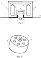
- a device for detecting mechanical vibrations or a vibration sensor 1 is in the Figure 1 seen in cross section.
- the vibration sensor 1 is shown schematically and not true to scale.
- the vibration sensor 1 has a housing 2, a vibration detection element 3, a total of six power sources 4 and a printed circuit board 5. On the circuit board there can be different in the Figure 1 Electronic components (not shown in more detail) that the vibration sensor 1 needs for its operation, such as a control unit, a data memory or a data transmission interface, can be arranged.
- the housing 2 is essentially of a hollow cylindrical shape. One side of the housing 2 is closed by a cover 6. In contrast, the side of the housing 2 facing away from the cover 6 is spanned by a rubber membrane 7. An outer surface of the rubber membrane 7 is provided as a contact surface of the housing 2, with which the housing 2 and thus the vibration sensor 1 as such can be placed or attached to surfaces of measurement objects.
- the rubber membrane 7 has an opening in its center, within which the vibration detection element 3 is arranged extending into the interior of the housing 2.
- An edge section 8 of the rubber membrane 7 surrounding the opening is turned inside the housing 2 and rests circumferentially on the vibration detection element 3.
- the power sources 4 and the printed circuit board 5 are also located inside the housing 2. With the exception of a recess 9, within which the vibration detection element 3 and the edge section 8 are arranged, the interior of the housing 2 is completely filled with a foam 10.
- a threaded section 11 is formed on the vibration detection element 3 outside the interior.
- the vibration sensor 1 for measuring oscillations or vibrations of a machine 12 is attached to the same as the measurement object, the threaded section 11 being screwed into the machine 12 at a point provided for this purpose or being screwed to the machine 12.
- Both the vibration detection element 3 comes into direct contact with a surface of the machine 12 and the outer surface of the rubber membrane 7, which forms the contact surface of the housing 2.
- a fixed connection of the housing 2 to the machine 12 is advantageous.
- the vibration sensor 1 can have magnets or an adhesive or adhesive connection can be formed between the contact surface of the housing 2 and the machine 12. After the oscillations or vibrations of the machine 12 have been measured, the vibration sensor 1 can be unscrewed from the machine 12 and removed from it.
- FIG. 2 Like in the Figure 2 can be seen showing a section through the vibration sensor 1 along the line in FIG Figure 1
- the dashed line shows the six current sources 4 of the vibration sensor 1 along one in the Figure 2 dashed circle at equal angular intervals around the vibration detection element 3 around.
- This uniform or symmetrical distribution of the current sources 4 around the vibration sensing element 3 requires in particular that the current sources 4 are not positioned above the vibration sensing element 3 but are located inside the housing 2 essentially at a comparable or the same height as the vibration sensing element 3.
- each power source 4 facing the machine 12 overlap or are aligned with an upper end section of the vibration detection element 3 facing away from the machine 12 in the normal direction to the longitudinal axis of the vibration sensor 1 or the vibration detection element 3.
- the power sources 4 are arranged relatively deep within the housing 2, so that when the vibration sensor 1 is applied to the machine 12 or to another measurement object, they are relatively close to the machine 12 or the measurement object.
- the center of gravity of the power sources 4 is also located relatively deep within the housing 2 and relatively close to the machine 12 or the measurement object.
- the height of the housing 2 is lower than with known vibration sensors, so that less high vibration amplitudes of the housing 2 can be excited and tilting vibrations of the housing 2 have less of an effect.
- the symmetrical arrangement of the power sources 4 or other components around the vibration detection element 3 and the resulting deep positioning of their centers of gravity within the housing 2 therefore have the effect of various transverse and longitudinal eigenmodes of the power sources 4 as well as tilting vibrations of the housing 2 on the measurement behavior of the vibration detection element 3 suppressed.
- FIG Figure 3 For example, a section through a vibration sensor 13 with only two current sources 14 and a centrally arranged vibration detection element 15. Both current sources 14 are arranged on one side of the vibration detection element 15 with the same along a straight line. At the same time, however, the current sources 14 are also uniform with the same angular spacing along the in FIG Figure 3 drawn dashed circle distributed, each 180 °.
- FIG 4 a cross section through a vibration sensor 16 with four current sources 17 and a central vibration detection element 18 can be seen.
- the four power sources 17 are uniformly along one in the Figure 4
- the circle drawn in dashed lines is distributed around the central vibration detection element 18.
- the angular distance between the current sources 17 is now 90 °.
- the angular distance in the case of n current sources symmetrically or uniformly distributed along a circle around a vibration detection element is 360 ° / n, where n is an integer equal to or greater than 2 is. It does not matter whether n is an even or an odd number.
- a vibration sensor 19 is shown with a total of eight current sources 20, which are arranged around a central vibration detection element 21. However, four current sources are now arranged at the same angular intervals along an inner circle 22, while the remaining four current sources are arranged at the same angular intervals along an outer circle 23 around the central vibration detection element 21.
- the two circles 22 and 23 are concentric to one another and the current sources 20 of the same are positioned along two mutually orthogonal lines.
- current sources of vibration sensors can also be arranged along more than just two circles. It is also possible for the number of current sources arranged along a circle to differ from circle to circle. For example, four current sources can be distributed along an inner circle and five or six current sources can be distributed along an outer circle.
Landscapes
- Physics & Mathematics (AREA)
- General Physics & Mathematics (AREA)
- Measurement Of Mechanical Vibrations Or Ultrasonic Waves (AREA)
Applications Claiming Priority (1)
| Application Number | Priority Date | Filing Date | Title |
|---|---|---|---|
| DE102019207168.6A DE102019207168A1 (de) | 2019-05-16 | 2019-05-16 | Vorrichtung zum Erfassen mechanischer Schwingungen |
Publications (2)
| Publication Number | Publication Date |
|---|---|
| EP3739308A1 true EP3739308A1 (fr) | 2020-11-18 |
| EP3739308B1 EP3739308B1 (fr) | 2022-01-19 |
Family
ID=70738321
Family Applications (1)
| Application Number | Title | Priority Date | Filing Date |
|---|---|---|---|
| EP20174873.8A Active EP3739308B1 (fr) | 2019-05-16 | 2020-05-15 | Dispositif de détection des vibrations mécaniques |
Country Status (3)
| Country | Link |
|---|---|
| US (1) | US11215502B2 (fr) |
| EP (1) | EP3739308B1 (fr) |
| DE (1) | DE102019207168A1 (fr) |
Citations (7)
| Publication number | Priority date | Publication date | Assignee | Title |
|---|---|---|---|---|
| WO2011104433A1 (fr) * | 2010-02-24 | 2011-09-01 | Espotel Oy | Système de surveillance pour surveiller l'état de pignons planétaires |
| US8640545B2 (en) | 2009-10-05 | 2014-02-04 | Pcb Piezotronics, Inc. | Vibration sensor with mechanical isolation member |
| WO2014148657A1 (fr) * | 2013-03-20 | 2014-09-25 | 케이티엠엔지니어링(주) | Dispositif de détection d'un dysfonctionnement luminescent par un capteur de vibrations |
| DE102014205922A1 (de) | 2014-03-31 | 2015-10-01 | Aktiebolaget Skf | Modul zum Erfassen eines Vibrationsverhaltens einer mechanischen Komponente |
| US9791310B2 (en) | 2014-06-10 | 2017-10-17 | Uptime Solutions | Vibration-sensing field unit |
| US20180071889A1 (en) * | 2016-09-15 | 2018-03-15 | Applied Materials, Inc. | Chemical mechanical polishing smart ring |
| US9921136B2 (en) | 2014-08-05 | 2018-03-20 | 01dB-Metravib, Societe Par Actions Simplifee | Wireless collection and analysis of machine data |
Family Cites Families (3)
| Publication number | Priority date | Publication date | Assignee | Title |
|---|---|---|---|---|
| JPH0310162A (ja) * | 1989-06-08 | 1991-01-17 | Fujikura Ltd | 圧電型加速度センサ装置 |
| US8590384B2 (en) * | 2006-04-03 | 2013-11-26 | Vonroll Infratec (Investment) Ag | Vibration sensor array |
| US10533920B2 (en) * | 2014-08-05 | 2020-01-14 | Acoem France | Automatic rotating-machine fault diagnosis with confidence level indication |
-
2019
- 2019-05-16 DE DE102019207168.6A patent/DE102019207168A1/de active Pending
-
2020
- 2020-05-15 US US16/875,086 patent/US11215502B2/en active Active
- 2020-05-15 EP EP20174873.8A patent/EP3739308B1/fr active Active
Patent Citations (7)
| Publication number | Priority date | Publication date | Assignee | Title |
|---|---|---|---|---|
| US8640545B2 (en) | 2009-10-05 | 2014-02-04 | Pcb Piezotronics, Inc. | Vibration sensor with mechanical isolation member |
| WO2011104433A1 (fr) * | 2010-02-24 | 2011-09-01 | Espotel Oy | Système de surveillance pour surveiller l'état de pignons planétaires |
| WO2014148657A1 (fr) * | 2013-03-20 | 2014-09-25 | 케이티엠엔지니어링(주) | Dispositif de détection d'un dysfonctionnement luminescent par un capteur de vibrations |
| DE102014205922A1 (de) | 2014-03-31 | 2015-10-01 | Aktiebolaget Skf | Modul zum Erfassen eines Vibrationsverhaltens einer mechanischen Komponente |
| US9791310B2 (en) | 2014-06-10 | 2017-10-17 | Uptime Solutions | Vibration-sensing field unit |
| US9921136B2 (en) | 2014-08-05 | 2018-03-20 | 01dB-Metravib, Societe Par Actions Simplifee | Wireless collection and analysis of machine data |
| US20180071889A1 (en) * | 2016-09-15 | 2018-03-15 | Applied Materials, Inc. | Chemical mechanical polishing smart ring |
Also Published As
| Publication number | Publication date |
|---|---|
| DE102019207168A1 (de) | 2020-11-19 |
| EP3739308B1 (fr) | 2022-01-19 |
| US11215502B2 (en) | 2022-01-04 |
| US20200363260A1 (en) | 2020-11-19 |
Similar Documents
| Publication | Publication Date | Title |
|---|---|---|
| DE3336991C2 (fr) | ||
| EP3729015B1 (fr) | Capteur vibronique | |
| DE3215040C2 (de) | Resonanzstab | |
| EP2659238B1 (fr) | Dispositif pour aligner un appareil de mesure | |
| DE3911341C1 (fr) | ||
| EP2464951A1 (fr) | Capteur à variables multiples pour la détermination et/ou la surveillance du niveau de remplissage et de la densité et/ou de la viscosité d'un liquide dans un réservoir | |
| DE102008050266A1 (de) | Vorrichtung zur Bestimmung und/oder Überwachung einer Prozessgröße eines Mediums | |
| DE102008015916B4 (de) | Verfahren und Vorrichtung zum Testen und Kalibrieren von elektronischen Halbleiterbauelementen, die Schall in elektrische Signale umwandeln | |
| DE102007012157A1 (de) | Modular aufgebaute Messachse | |
| EP0320442B1 (fr) | Application d'un résonateur diélectrique d'hyperfréquence et circuit de détection | |
| DE19720519C2 (de) | Vorrichtung zur Feststellung und/oder Überwachung eines Füllstandes eines Mediums in einem Behälter | |
| DE3348119C2 (en) | Device for ascertaining and/or monitoring a predetermined filling level in a container | |
| EP3739308B1 (fr) | Dispositif de détection des vibrations mécaniques | |
| DE3280443T2 (de) | Verbesserte vorrichtung zur isolierung von erschütterungen. | |
| DE60014591T2 (de) | Aktives, schwingungsdämpfendes system für schneidewerkzeuge | |
| DE102008050326A1 (de) | Vorrichtung zur Bestimmung und/oder Überwachung einer Prozessgröße eines Mediums | |
| EP2779031B1 (fr) | Procédé de mesure et dispositif de mesure | |
| EP0875739B1 (fr) | Dispositif pour la détermination et/ou la surveillance d'un niveau prédéterminé dans un réservoir | |
| EP3100009A1 (fr) | Dispositif de mesure d'éléments de transmission de données et de lecture de données couplés magnétiquement | |
| DE102019109311B3 (de) | Anordnung und Verfahren zur Kalibrierung und Betrieb von kapazitiven Aktoren | |
| DE102013102712A1 (de) | Vorrichtung zur Bestimmung und/oder Überwachung einer Prozessgröße eines Mediums | |
| DE1402994B2 (de) | Vorrichtung zur ueberwachung und regelung der relativen lage eines beweglichen teils bezueglich einer umlaufenden welle | |
| DE102016125822A1 (de) | Vibrationssensor | |
| EP0875740A1 (fr) | Dispositif pour la détermination et/ou la surveillance d'un niveau prédéterminé dans un réservoir | |
| DE102004018506A1 (de) | Verfahren und Vorrichtung zur Herstellung einer Messvorrichtung zur Bestimmung und/oder Überwachung einer Prozessgröße und entsprechende Messvorrichtung |
Legal Events
| Date | Code | Title | Description |
|---|---|---|---|
| PUAI | Public reference made under article 153(3) epc to a published international application that has entered the european phase |
Free format text: ORIGINAL CODE: 0009012 |
|
| STAA | Information on the status of an ep patent application or granted ep patent |
Free format text: STATUS: THE APPLICATION HAS BEEN PUBLISHED |
|
| AK | Designated contracting states |
Kind code of ref document: A1 Designated state(s): AL AT BE BG CH CY CZ DE DK EE ES FI FR GB GR HR HU IE IS IT LI LT LU LV MC MK MT NL NO PL PT RO RS SE SI SK SM TR |
|
| AX | Request for extension of the european patent |
Extension state: BA ME |
|
| STAA | Information on the status of an ep patent application or granted ep patent |
Free format text: STATUS: REQUEST FOR EXAMINATION WAS MADE |
|
| 17P | Request for examination filed |
Effective date: 20210303 |
|
| RBV | Designated contracting states (corrected) |
Designated state(s): AL AT BE BG CH CY CZ DE DK EE ES FI FR GB GR HR HU IE IS IT LI LT LU LV MC MK MT NL NO PL PT RO RS SE SI SK SM TR |
|
| RAP3 | Party data changed (applicant data changed or rights of an application transferred) |
Owner name: PRUEFTECHNIK DIETER BUSCH GMBH |
|
| GRAP | Despatch of communication of intention to grant a patent |
Free format text: ORIGINAL CODE: EPIDOSNIGR1 |
|
| STAA | Information on the status of an ep patent application or granted ep patent |
Free format text: STATUS: GRANT OF PATENT IS INTENDED |
|
| INTG | Intention to grant announced |
Effective date: 20211008 |
|
| GRAS | Grant fee paid |
Free format text: ORIGINAL CODE: EPIDOSNIGR3 |
|
| GRAA | (expected) grant |
Free format text: ORIGINAL CODE: 0009210 |
|
| STAA | Information on the status of an ep patent application or granted ep patent |
Free format text: STATUS: THE PATENT HAS BEEN GRANTED |
|
| AK | Designated contracting states |
Kind code of ref document: B1 Designated state(s): AL AT BE BG CH CY CZ DE DK EE ES FI FR GB GR HR HU IE IS IT LI LT LU LV MC MK MT NL NO PL PT RO RS SE SI SK SM TR |
|
| REG | Reference to a national code |
Ref country code: GB Ref legal event code: FG4D Free format text: NOT ENGLISH |
|
| REG | Reference to a national code |
Ref country code: CH Ref legal event code: EP |
|
| REG | Reference to a national code |
Ref country code: DE Ref legal event code: R096 Ref document number: 502020000569 Country of ref document: DE |
|
| REG | Reference to a national code |
Ref country code: AT Ref legal event code: REF Ref document number: 1464060 Country of ref document: AT Kind code of ref document: T Effective date: 20220215 |
|
| REG | Reference to a national code |
Ref country code: IE Ref legal event code: FG4D Free format text: LANGUAGE OF EP DOCUMENT: GERMAN |
|
| REG | Reference to a national code |
Ref country code: LT Ref legal event code: MG9D |
|
| REG | Reference to a national code |
Ref country code: NL Ref legal event code: MP Effective date: 20220119 |
|
| PG25 | Lapsed in a contracting state [announced via postgrant information from national office to epo] |
Ref country code: NL Free format text: LAPSE BECAUSE OF FAILURE TO SUBMIT A TRANSLATION OF THE DESCRIPTION OR TO PAY THE FEE WITHIN THE PRESCRIBED TIME-LIMIT Effective date: 20220119 |
|
| PG25 | Lapsed in a contracting state [announced via postgrant information from national office to epo] |
Ref country code: SE Free format text: LAPSE BECAUSE OF FAILURE TO SUBMIT A TRANSLATION OF THE DESCRIPTION OR TO PAY THE FEE WITHIN THE PRESCRIBED TIME-LIMIT Effective date: 20220119 Ref country code: RS Free format text: LAPSE BECAUSE OF FAILURE TO SUBMIT A TRANSLATION OF THE DESCRIPTION OR TO PAY THE FEE WITHIN THE PRESCRIBED TIME-LIMIT Effective date: 20220119 Ref country code: PT Free format text: LAPSE BECAUSE OF FAILURE TO SUBMIT A TRANSLATION OF THE DESCRIPTION OR TO PAY THE FEE WITHIN THE PRESCRIBED TIME-LIMIT Effective date: 20220519 Ref country code: NO Free format text: LAPSE BECAUSE OF FAILURE TO SUBMIT A TRANSLATION OF THE DESCRIPTION OR TO PAY THE FEE WITHIN THE PRESCRIBED TIME-LIMIT Effective date: 20220419 Ref country code: LT Free format text: LAPSE BECAUSE OF FAILURE TO SUBMIT A TRANSLATION OF THE DESCRIPTION OR TO PAY THE FEE WITHIN THE PRESCRIBED TIME-LIMIT Effective date: 20220119 Ref country code: HR Free format text: LAPSE BECAUSE OF FAILURE TO SUBMIT A TRANSLATION OF THE DESCRIPTION OR TO PAY THE FEE WITHIN THE PRESCRIBED TIME-LIMIT Effective date: 20220119 Ref country code: ES Free format text: LAPSE BECAUSE OF FAILURE TO SUBMIT A TRANSLATION OF THE DESCRIPTION OR TO PAY THE FEE WITHIN THE PRESCRIBED TIME-LIMIT Effective date: 20220119 Ref country code: BG Free format text: LAPSE BECAUSE OF FAILURE TO SUBMIT A TRANSLATION OF THE DESCRIPTION OR TO PAY THE FEE WITHIN THE PRESCRIBED TIME-LIMIT Effective date: 20220419 |
|
| PG25 | Lapsed in a contracting state [announced via postgrant information from national office to epo] |
Ref country code: PL Free format text: LAPSE BECAUSE OF FAILURE TO SUBMIT A TRANSLATION OF THE DESCRIPTION OR TO PAY THE FEE WITHIN THE PRESCRIBED TIME-LIMIT Effective date: 20220119 Ref country code: LV Free format text: LAPSE BECAUSE OF FAILURE TO SUBMIT A TRANSLATION OF THE DESCRIPTION OR TO PAY THE FEE WITHIN THE PRESCRIBED TIME-LIMIT Effective date: 20220119 Ref country code: GR Free format text: LAPSE BECAUSE OF FAILURE TO SUBMIT A TRANSLATION OF THE DESCRIPTION OR TO PAY THE FEE WITHIN THE PRESCRIBED TIME-LIMIT Effective date: 20220420 Ref country code: FI Free format text: LAPSE BECAUSE OF FAILURE TO SUBMIT A TRANSLATION OF THE DESCRIPTION OR TO PAY THE FEE WITHIN THE PRESCRIBED TIME-LIMIT Effective date: 20220119 |
|
| PG25 | Lapsed in a contracting state [announced via postgrant information from national office to epo] |
Ref country code: IS Free format text: LAPSE BECAUSE OF FAILURE TO SUBMIT A TRANSLATION OF THE DESCRIPTION OR TO PAY THE FEE WITHIN THE PRESCRIBED TIME-LIMIT Effective date: 20220519 |
|
| REG | Reference to a national code |
Ref country code: DE Ref legal event code: R097 Ref document number: 502020000569 Country of ref document: DE |
|
| PG25 | Lapsed in a contracting state [announced via postgrant information from national office to epo] |
Ref country code: SM Free format text: LAPSE BECAUSE OF FAILURE TO SUBMIT A TRANSLATION OF THE DESCRIPTION OR TO PAY THE FEE WITHIN THE PRESCRIBED TIME-LIMIT Effective date: 20220119 Ref country code: SK Free format text: LAPSE BECAUSE OF FAILURE TO SUBMIT A TRANSLATION OF THE DESCRIPTION OR TO PAY THE FEE WITHIN THE PRESCRIBED TIME-LIMIT Effective date: 20220119 Ref country code: RO Free format text: LAPSE BECAUSE OF FAILURE TO SUBMIT A TRANSLATION OF THE DESCRIPTION OR TO PAY THE FEE WITHIN THE PRESCRIBED TIME-LIMIT Effective date: 20220119 Ref country code: EE Free format text: LAPSE BECAUSE OF FAILURE TO SUBMIT A TRANSLATION OF THE DESCRIPTION OR TO PAY THE FEE WITHIN THE PRESCRIBED TIME-LIMIT Effective date: 20220119 Ref country code: DK Free format text: LAPSE BECAUSE OF FAILURE TO SUBMIT A TRANSLATION OF THE DESCRIPTION OR TO PAY THE FEE WITHIN THE PRESCRIBED TIME-LIMIT Effective date: 20220119 Ref country code: CZ Free format text: LAPSE BECAUSE OF FAILURE TO SUBMIT A TRANSLATION OF THE DESCRIPTION OR TO PAY THE FEE WITHIN THE PRESCRIBED TIME-LIMIT Effective date: 20220119 |
|
| PLBE | No opposition filed within time limit |
Free format text: ORIGINAL CODE: 0009261 |
|
| STAA | Information on the status of an ep patent application or granted ep patent |
Free format text: STATUS: NO OPPOSITION FILED WITHIN TIME LIMIT |
|
| PG25 | Lapsed in a contracting state [announced via postgrant information from national office to epo] |
Ref country code: AL Free format text: LAPSE BECAUSE OF FAILURE TO SUBMIT A TRANSLATION OF THE DESCRIPTION OR TO PAY THE FEE WITHIN THE PRESCRIBED TIME-LIMIT Effective date: 20220119 |
|
| 26N | No opposition filed |
Effective date: 20221020 |
|
| REG | Reference to a national code |
Ref country code: BE Ref legal event code: MM Effective date: 20220531 |
|
| PG25 | Lapsed in a contracting state [announced via postgrant information from national office to epo] |
Ref country code: MC Free format text: LAPSE BECAUSE OF FAILURE TO SUBMIT A TRANSLATION OF THE DESCRIPTION OR TO PAY THE FEE WITHIN THE PRESCRIBED TIME-LIMIT Effective date: 20220119 Ref country code: LU Free format text: LAPSE BECAUSE OF NON-PAYMENT OF DUE FEES Effective date: 20220515 |
|
| PG25 | Lapsed in a contracting state [announced via postgrant information from national office to epo] |
Ref country code: SI Free format text: LAPSE BECAUSE OF FAILURE TO SUBMIT A TRANSLATION OF THE DESCRIPTION OR TO PAY THE FEE WITHIN THE PRESCRIBED TIME-LIMIT Effective date: 20220119 |
|
| PG25 | Lapsed in a contracting state [announced via postgrant information from national office to epo] |
Ref country code: IE Free format text: LAPSE BECAUSE OF NON-PAYMENT OF DUE FEES Effective date: 20220515 |
|
| PG25 | Lapsed in a contracting state [announced via postgrant information from national office to epo] |
Ref country code: BE Free format text: LAPSE BECAUSE OF NON-PAYMENT OF DUE FEES Effective date: 20220531 |
|
| PG25 | Lapsed in a contracting state [announced via postgrant information from national office to epo] |
Ref country code: IT Free format text: LAPSE BECAUSE OF FAILURE TO SUBMIT A TRANSLATION OF THE DESCRIPTION OR TO PAY THE FEE WITHIN THE PRESCRIBED TIME-LIMIT Effective date: 20220119 |
|
| REG | Reference to a national code |
Ref country code: CH Ref legal event code: PL |
|
| PG25 | Lapsed in a contracting state [announced via postgrant information from national office to epo] |
Ref country code: LI Free format text: LAPSE BECAUSE OF NON-PAYMENT OF DUE FEES Effective date: 20230531 Ref country code: CH Free format text: LAPSE BECAUSE OF NON-PAYMENT OF DUE FEES Effective date: 20230531 |
|
| PG25 | Lapsed in a contracting state [announced via postgrant information from national office to epo] |
Ref country code: MK Free format text: LAPSE BECAUSE OF FAILURE TO SUBMIT A TRANSLATION OF THE DESCRIPTION OR TO PAY THE FEE WITHIN THE PRESCRIBED TIME-LIMIT Effective date: 20220119 Ref country code: CY Free format text: LAPSE BECAUSE OF FAILURE TO SUBMIT A TRANSLATION OF THE DESCRIPTION OR TO PAY THE FEE WITHIN THE PRESCRIBED TIME-LIMIT Effective date: 20220119 |
|
| PG25 | Lapsed in a contracting state [announced via postgrant information from national office to epo] |
Ref country code: HU Free format text: LAPSE BECAUSE OF FAILURE TO SUBMIT A TRANSLATION OF THE DESCRIPTION OR TO PAY THE FEE WITHIN THE PRESCRIBED TIME-LIMIT; INVALID AB INITIO Effective date: 20200515 |
|
| PG25 | Lapsed in a contracting state [announced via postgrant information from national office to epo] |
Ref country code: MT Free format text: LAPSE BECAUSE OF FAILURE TO SUBMIT A TRANSLATION OF THE DESCRIPTION OR TO PAY THE FEE WITHIN THE PRESCRIBED TIME-LIMIT Effective date: 20220119 |
|
| PGFP | Annual fee paid to national office [announced via postgrant information from national office to epo] |
Ref country code: DE Payment date: 20250528 Year of fee payment: 6 |
|
| PGFP | Annual fee paid to national office [announced via postgrant information from national office to epo] |
Ref country code: GB Payment date: 20250520 Year of fee payment: 6 |
|
| PGFP | Annual fee paid to national office [announced via postgrant information from national office to epo] |
Ref country code: FR Payment date: 20250526 Year of fee payment: 6 |
|
| PGFP | Annual fee paid to national office [announced via postgrant information from national office to epo] |
Ref country code: AT Payment date: 20250721 Year of fee payment: 5 |
|
| PG25 | Lapsed in a contracting state [announced via postgrant information from national office to epo] |
Ref country code: TR Free format text: LAPSE BECAUSE OF FAILURE TO SUBMIT A TRANSLATION OF THE DESCRIPTION OR TO PAY THE FEE WITHIN THE PRESCRIBED TIME-LIMIT Effective date: 20220119 |