EP3739741A1 - Convertisseur élévateur entrelacé avec multiplicateur capacitif pour commande de del - Google Patents
Convertisseur élévateur entrelacé avec multiplicateur capacitif pour commande de del Download PDFInfo
- Publication number
- EP3739741A1 EP3739741A1 EP20173202.1A EP20173202A EP3739741A1 EP 3739741 A1 EP3739741 A1 EP 3739741A1 EP 20173202 A EP20173202 A EP 20173202A EP 3739741 A1 EP3739741 A1 EP 3739741A1
- Authority
- EP
- European Patent Office
- Prior art keywords
- boost converter
- boost
- switching element
- input
- interleaved
- Prior art date
- Legal status (The legal status is an assumption and is not a legal conclusion. Google has not performed a legal analysis and makes no representation as to the accuracy of the status listed.)
- Pending
Links
- 238000000034 method Methods 0.000 claims abstract description 26
- 239000003990 capacitor Substances 0.000 claims description 31
- 230000005669 field effect Effects 0.000 claims description 3
- 239000004065 semiconductor Substances 0.000 claims description 3
- 229910044991 metal oxide Inorganic materials 0.000 claims 2
- 150000004706 metal oxides Chemical class 0.000 claims 2
- 230000010355 oscillation Effects 0.000 claims 2
- 230000008569 process Effects 0.000 description 8
- 238000012546 transfer Methods 0.000 description 8
- 238000010586 diagram Methods 0.000 description 5
- 239000000203 mixture Substances 0.000 description 4
- 238000003491 array Methods 0.000 description 2
- 230000008901 benefit Effects 0.000 description 2
- 230000008878 coupling Effects 0.000 description 2
- 238000010168 coupling process Methods 0.000 description 2
- 238000005859 coupling reaction Methods 0.000 description 2
- 238000013461 design Methods 0.000 description 2
- 238000004891 communication Methods 0.000 description 1
- 238000004590 computer program Methods 0.000 description 1
- 238000007796 conventional method Methods 0.000 description 1
- 238000005516 engineering process Methods 0.000 description 1
- 238000002955 isolation Methods 0.000 description 1
- 239000000463 material Substances 0.000 description 1
- 238000005259 measurement Methods 0.000 description 1
- 230000015654 memory Effects 0.000 description 1
- 238000012986 modification Methods 0.000 description 1
- 230000004048 modification Effects 0.000 description 1
Images

Classifications
-
- H—ELECTRICITY
- H02—GENERATION; CONVERSION OR DISTRIBUTION OF ELECTRIC POWER
- H02M—APPARATUS FOR CONVERSION BETWEEN AC AND AC, BETWEEN AC AND DC, OR BETWEEN DC AND DC, AND FOR USE WITH MAINS OR SIMILAR POWER SUPPLY SYSTEMS; CONVERSION OF DC OR AC INPUT POWER INTO SURGE OUTPUT POWER; CONTROL OR REGULATION THEREOF
- H02M3/00—Conversion of DC power input into DC power output
- H02M3/02—Conversion of DC power input into DC power output without intermediate conversion into AC
- H02M3/04—Conversion of DC power input into DC power output without intermediate conversion into AC by static converters
- H02M3/10—Conversion of DC power input into DC power output without intermediate conversion into AC by static converters using discharge tubes with control electrode or semiconductor devices with control electrode
- H02M3/145—Conversion of DC power input into DC power output without intermediate conversion into AC by static converters using discharge tubes with control electrode or semiconductor devices with control electrode using devices of a triode or transistor type requiring continuous application of a control signal
- H02M3/155—Conversion of DC power input into DC power output without intermediate conversion into AC by static converters using discharge tubes with control electrode or semiconductor devices with control electrode using devices of a triode or transistor type requiring continuous application of a control signal using semiconductor devices only
- H02M3/156—Conversion of DC power input into DC power output without intermediate conversion into AC by static converters using discharge tubes with control electrode or semiconductor devices with control electrode using devices of a triode or transistor type requiring continuous application of a control signal using semiconductor devices only with automatic control of output voltage or current, e.g. switching regulators
- H02M3/158—Conversion of DC power input into DC power output without intermediate conversion into AC by static converters using discharge tubes with control electrode or semiconductor devices with control electrode using devices of a triode or transistor type requiring continuous application of a control signal using semiconductor devices only with automatic control of output voltage or current, e.g. switching regulators including plural semiconductor devices as final control devices for a single load
- H02M3/1584—Conversion of DC power input into DC power output without intermediate conversion into AC by static converters using discharge tubes with control electrode or semiconductor devices with control electrode using devices of a triode or transistor type requiring continuous application of a control signal using semiconductor devices only with automatic control of output voltage or current, e.g. switching regulators including plural semiconductor devices as final control devices for a single load with a plurality of power processing stages connected in parallel
-
- H—ELECTRICITY
- H05—ELECTRIC TECHNIQUES NOT OTHERWISE PROVIDED FOR
- H05B—ELECTRIC HEATING; ELECTRIC LIGHT SOURCES NOT OTHERWISE PROVIDED FOR; CIRCUIT ARRANGEMENTS FOR ELECTRIC LIGHT SOURCES, IN GENERAL
- H05B45/00—Circuit arrangements for operating light-emitting diodes [LED]
- H05B45/30—Driver circuits
- H05B45/37—Converter circuits
- H05B45/3725—Switched mode power supply [SMPS]
- H05B45/38—Switched mode power supply [SMPS] using boost topology
-
- H—ELECTRICITY
- H02—GENERATION; CONVERSION OR DISTRIBUTION OF ELECTRIC POWER
- H02M—APPARATUS FOR CONVERSION BETWEEN AC AND AC, BETWEEN AC AND DC, OR BETWEEN DC AND DC, AND FOR USE WITH MAINS OR SIMILAR POWER SUPPLY SYSTEMS; CONVERSION OF DC OR AC INPUT POWER INTO SURGE OUTPUT POWER; CONTROL OR REGULATION THEREOF
- H02M3/00—Conversion of DC power input into DC power output
- H02M3/02—Conversion of DC power input into DC power output without intermediate conversion into AC
- H02M3/04—Conversion of DC power input into DC power output without intermediate conversion into AC by static converters
- H02M3/06—Conversion of DC power input into DC power output without intermediate conversion into AC by static converters using resistors or capacitors, e.g. potential divider
- H02M3/07—Conversion of DC power input into DC power output without intermediate conversion into AC by static converters using resistors or capacitors, e.g. potential divider using capacitors charged and discharged alternately by semiconductor devices with control electrode, e.g. charge pumps
-
- H—ELECTRICITY
- H02—GENERATION; CONVERSION OR DISTRIBUTION OF ELECTRIC POWER
- H02M—APPARATUS FOR CONVERSION BETWEEN AC AND AC, BETWEEN AC AND DC, OR BETWEEN DC AND DC, AND FOR USE WITH MAINS OR SIMILAR POWER SUPPLY SYSTEMS; CONVERSION OF DC OR AC INPUT POWER INTO SURGE OUTPUT POWER; CONTROL OR REGULATION THEREOF
- H02M3/00—Conversion of DC power input into DC power output
- H02M3/02—Conversion of DC power input into DC power output without intermediate conversion into AC
- H02M3/04—Conversion of DC power input into DC power output without intermediate conversion into AC by static converters
- H02M3/10—Conversion of DC power input into DC power output without intermediate conversion into AC by static converters using discharge tubes with control electrode or semiconductor devices with control electrode
- H02M3/125—Conversion of DC power input into DC power output without intermediate conversion into AC by static converters using discharge tubes with control electrode or semiconductor devices with control electrode using devices of a thyratron or thyristor type requiring extinguishing means
- H02M3/135—Conversion of DC power input into DC power output without intermediate conversion into AC by static converters using discharge tubes with control electrode or semiconductor devices with control electrode using devices of a thyratron or thyristor type requiring extinguishing means using semiconductor devices only
- H02M3/137—Conversion of DC power input into DC power output without intermediate conversion into AC by static converters using discharge tubes with control electrode or semiconductor devices with control electrode using devices of a thyratron or thyristor type requiring extinguishing means using semiconductor devices only with automatic control of output voltage or current, e.g. switching regulators
- H02M3/142—Conversion of DC power input into DC power output without intermediate conversion into AC by static converters using discharge tubes with control electrode or semiconductor devices with control electrode using devices of a thyratron or thyristor type requiring extinguishing means using semiconductor devices only with automatic control of output voltage or current, e.g. switching regulators including plural semiconductor devices as final control devices for a single load
-
- H—ELECTRICITY
- H02—GENERATION; CONVERSION OR DISTRIBUTION OF ELECTRIC POWER
- H02M—APPARATUS FOR CONVERSION BETWEEN AC AND AC, BETWEEN AC AND DC, OR BETWEEN DC AND DC, AND FOR USE WITH MAINS OR SIMILAR POWER SUPPLY SYSTEMS; CONVERSION OF DC OR AC INPUT POWER INTO SURGE OUTPUT POWER; CONTROL OR REGULATION THEREOF
- H02M3/00—Conversion of DC power input into DC power output
- H02M3/02—Conversion of DC power input into DC power output without intermediate conversion into AC
- H02M3/04—Conversion of DC power input into DC power output without intermediate conversion into AC by static converters
- H02M3/06—Conversion of DC power input into DC power output without intermediate conversion into AC by static converters using resistors or capacitors, e.g. potential divider
- H02M3/07—Conversion of DC power input into DC power output without intermediate conversion into AC by static converters using resistors or capacitors, e.g. potential divider using capacitors charged and discharged alternately by semiconductor devices with control electrode, e.g. charge pumps
- H02M3/073—Charge pumps of the Schenkel-type
-
- H—ELECTRICITY
- H02—GENERATION; CONVERSION OR DISTRIBUTION OF ELECTRIC POWER
- H02M—APPARATUS FOR CONVERSION BETWEEN AC AND AC, BETWEEN AC AND DC, OR BETWEEN DC AND DC, AND FOR USE WITH MAINS OR SIMILAR POWER SUPPLY SYSTEMS; CONVERSION OF DC OR AC INPUT POWER INTO SURGE OUTPUT POWER; CONTROL OR REGULATION THEREOF
- H02M3/00—Conversion of DC power input into DC power output
- H02M3/02—Conversion of DC power input into DC power output without intermediate conversion into AC
- H02M3/04—Conversion of DC power input into DC power output without intermediate conversion into AC by static converters
- H02M3/10—Conversion of DC power input into DC power output without intermediate conversion into AC by static converters using discharge tubes with control electrode or semiconductor devices with control electrode
- H02M3/145—Conversion of DC power input into DC power output without intermediate conversion into AC by static converters using discharge tubes with control electrode or semiconductor devices with control electrode using devices of a triode or transistor type requiring continuous application of a control signal
- H02M3/155—Conversion of DC power input into DC power output without intermediate conversion into AC by static converters using discharge tubes with control electrode or semiconductor devices with control electrode using devices of a triode or transistor type requiring continuous application of a control signal using semiconductor devices only
- H02M3/156—Conversion of DC power input into DC power output without intermediate conversion into AC by static converters using discharge tubes with control electrode or semiconductor devices with control electrode using devices of a triode or transistor type requiring continuous application of a control signal using semiconductor devices only with automatic control of output voltage or current, e.g. switching regulators
- H02M3/158—Conversion of DC power input into DC power output without intermediate conversion into AC by static converters using discharge tubes with control electrode or semiconductor devices with control electrode using devices of a triode or transistor type requiring continuous application of a control signal using semiconductor devices only with automatic control of output voltage or current, e.g. switching regulators including plural semiconductor devices as final control devices for a single load
- H02M3/1584—Conversion of DC power input into DC power output without intermediate conversion into AC by static converters using discharge tubes with control electrode or semiconductor devices with control electrode using devices of a triode or transistor type requiring continuous application of a control signal using semiconductor devices only with automatic control of output voltage or current, e.g. switching regulators including plural semiconductor devices as final control devices for a single load with a plurality of power processing stages connected in parallel
- H02M3/1586—Conversion of DC power input into DC power output without intermediate conversion into AC by static converters using discharge tubes with control electrode or semiconductor devices with control electrode using devices of a triode or transistor type requiring continuous application of a control signal using semiconductor devices only with automatic control of output voltage or current, e.g. switching regulators including plural semiconductor devices as final control devices for a single load with a plurality of power processing stages connected in parallel switched with a phase shift, i.e. interleaved
Definitions
- the present invention generally relates to light emitting diodes (LEDs), and more specifically, to circuit and method for an interleaved boost converter with capacitive multiplier for high power LED drive.
- LEDs light emitting diodes
- LEDs can be utilized in many power sensitive applications such as, for example, displays and low power electronic devices in aircraft lighting systems, aircraft interiors, aircraft display, landing lights, strobe lights for flashing emergency needs, automobiles, and commercial uses.
- current LED driving circuits utilizing boost converters and transformers suffer from shortages in LED drive voltages and power loss.
- Conventional high frequency switched boost converter / transformer based converters can face losses in power sensitive applications for LED drives, displays, non-volatile memories and low power high-voltage electronic devices in aircraft, automobiles, and consumer electronics.
- Embodiments of the present invention are directed to system.
- a non-limiting example of the system includes an interleaved boost converter including a first boost converter and a second boost converter, the second boost converter interleaved with the first boost converter, an electronic filter comprising an input and an output, wherein the input of the electronic filter is coupled to an output of the interleaved boost converter, a set of light-emitting diodes (LEDs) coupled to an output of the electronic filter, and a power source coupled to an input of the interleaved boost converter.
- an interleaved boost converter including a first boost converter and a second boost converter, the second boost converter interleaved with the first boost converter, an electronic filter comprising an input and an output, wherein the input of the electronic filter is coupled to an output of the interleaved boost converter, a set of light-emitting diodes (LEDs) coupled to an output of the electronic filter, and a power source coupled to an input of the interleaved boost converter.
- Embodiments of the present invention are directed to a method for operating an LED circuit.
- a non-limiting example of the method includes providing an interleaved boost converter including a first boost converter and a second boost converter, the second boost converter interleaved with the first boost converter, operating a first switching element to control a first boost convertor in the LED driver circuit, wherein the first boost convertor is in an ON state responsive to the first switching element being in an ON state, operating a second switching element to control a first boost convertor in the LED driver circuit, wherein the second boost convertor is in an ON state responsive to the first switching element being in an ON state, providing a set of LEDs, wherein the interleaved boost converter provides a step-up voltage to the set of LEDs.
- LEDs can be utilized in many power sensitive applications such as, for example, displays and low power electronic devices in aircraft lighting systems, aircraft interiors, aircraft display, landing lights, strobe lights for flashing emergency needs, automobiles, and other commercial uses.
- power sensitive applications such as, for example, displays and low power electronic devices in aircraft lighting systems, aircraft interiors, aircraft display, landing lights, strobe lights for flashing emergency needs, automobiles, and other commercial uses.
- current LED driving circuits suffer from shortages in LED drive voltages and power loss.
- Embodiments include a circuit topology configured in an energy efficient manner where electromagnetic interference due to inductance is significantly reduced.
- the circuit topology utilizes power electronics including a transformer to provide voltage step-up and isolation between the input and output which turn increases weight and the size of a converter. Because of this, a voltage multiplier stage is included in the circuit topology that generates the required high-voltage.
- FIG. 1 depicts a circuit topology for an LED driving circuit according to one or more embodiments.
- the LED driving circuit 100 includes two pulse generators (O1, O2) and a constant voltage source V1 that are utilized to operate the boost and capacitor switches.
- the interleaved boost converters are configured to work 180 degrees out of phase with each other because the capacitive multiplier will transfer energy from one to another effectively in this LED driving circuit 100.
- the duty cycle for the two pulse generators is maintained some for both of the boost converters; therefore if boost converter 1 (i.e., C1, C3, C5) is operated at 40% duty cycle, for example, then boost converter 2 (i.e., C2, C4, C6) consistently maintains to be the same duty cycle.
- the LED driving circuit 100 includes switches M1, M2 which, in some embodiments, are n-channel metal-oxide-semiconductor field-effect transistors (MOSFETs).
- the LED driving circuit 100 also includes comparator A3 and two-input AND logic gates A1, A2. The comparator A3 senses the current feedback on the set of LEDs 110 and cuts off the switch drive when sense resistor R1 exceeds a threshold voltage (Vref).
- the LED driving circuit 100 includes voltage source V1 which provides a forward bias for the diode chain to be in a conducting state and these diodes (D3 ... D9) are connected to one end of the capacitors (C1, C2, ..., C6). While the illustrated example shows a total of six (6) capacitor stages, in one or more embodiments, any number of capacitor stages can be utilized based on the output load. Voltage source V1 and the boost converter output will charge the capacitors at each switching cycle. In one or more embodiments, the voltage source V1 is equal to 10V.
- inductor L1 will store energy when M1 switch is 'On' and when M1 switch is 'Off the voltage is transferred to one end of C1, C3, and C5 capacitor nodes.
- inductor L2 will store energy when M2 is 'On' and then the voltage is transferred to one end of C2, C4, C6 capacitor nodes when switch M2 is 'Off'.
- This interleaving boost topology will retain higher efficiency due to load current sharing between two inductors and reduced switching loss; thereby the converter can be operated at lower frequency rather than at higher frequency as compared to utilizing a single boost converter.
- diode D1 and capacitor C9 are implemented to operate the diode chain capacitive multiplier during slighter load conditions.
- L1 M1 is switching; during Mloff period the reference voltage node of C1, C3, C5 will be equal to boost output voltage.
- the L1 output voltage goes to 0V. Therefore in each switching cycle the capacitor array C1, C3, C5 will be charged and discharged.
- M2 is OFF, L1 output voltage is steered through D1 to C2, C4, C6 reference node. Therefore C2, C4, C6 reference node will have voltage level equivalent to the charged voltage across C9 + L2 + V1.
- capacitor C9 charges from the L1 output voltage and L2 is charged from V1.
- V1 + L2 + C9 acts as boost charge pump. This principle is repeated for subsequent switching cycles.
- D1 will isolate the L1 circuit path from L2 (i.e., acts as steering diode charge transfer from L1 to L2 and reverse bias for L2 to L1 current path.
- the charging time constant of capacitor C1 to C6 depends on the amount of current supplied by the power supply V1 (power supply internal series resistance).
- An some embodiments, an arrangement to limit charge current can be achieved by adding a series resistor between V1 and D3.
- capacitor C1 will be charged from voltage source V1 with respect to a 0V through diode D3.
- Capacitor C1 will transfer voltage to capacitor C2 through diode D4.
- capacitor C2 will transfer voltage to capacitor C3 through diode D5.
- Capacitor C3 will then transfer voltage to capacitor C4 through diode D6.
- Capacitor C4 will transfer voltage to capacitor C5 through diode D7.
- Capacitor C5 will transfer voltage to capacitor C6 through diode D8.
- capacitor C6 will transfer voltage to capacitor C7 through diode D9.
- capacitor C7 will output the required load voltage.
- the output voltage in this chain will be equal to the voltage across capacitor C6 minus the voltage drop for the last diode in series.
- an LC pi-filter 106 at the output of the interleaved boost convertors is implemented to reduce voltage and current ripple content for the power LED drive. This allows for providing almost constant voltage for LED drive to reduce LED flickering and increase reliability of LED failures.
- a set of LEDs 110 is being driven by the LED driver circuit 100.
- the set of LEDs 110 included a total of 39 cool-white power LEDs in series. With a minimum forward bias for each diode of 3.2V having an average current of 100 mA and a maximum forward bias of 3.85V having average current of 1500 mA.
- the set of LEDs 110 can be operated within this region for minimum to maximum luminance.
- the single operated boost converter stage (L1, M1) will tend to increase the output voltage until the set of LEDs 110 gets into forward bias and the output current is minimum due to a single converter. Further, the peak switching voltage will be high enough to deliver the required voltage for LED conduction, therefore the current will be minimum in the operating region.
- the forward bias voltage is increased further in the operating region.
- the forward current is increased linearly within the LED operating characteristics with the applied voltage which increases the luminance of the set of LEDs 110.
- the current is shared between two boost converters which reduces the peak switching voltage and outputs more current as compared to a single stage boost converter.
- the duty cycle of the boost converter is varied to obtain minimum and maximum luminance.
- the switching frequency of the converter is varied to obtain optimal switching loss depending on the number of LED arrays and the current consumption of the LED arrays.
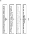
- FIG. 2 depicts a flow diagram of a method for operating an LED driver circuit according to one or more embodiments.
- the method 200 includes providing an interleaved boost converter comprising a first boost converter and a second boost converter, the second boost converter interleaved with the first boost converter, as shown in block 202.
- the method 200 includes operating a first switching element to control a first boost convertor in the LED driver circuit, wherein the first boost convertor is in an ON state responsive to the first switching element being in an ON state.
- the method 200 includes operating a second switching element to control a first boost convertor in the LED driver circuit, wherein the second boost convertor is in an ON state responsive to the first switching element being in an ON state, as shown in block 206.
- the method 200 includes providing a set of LEDs, wherein the interleaved boost converter provides a step-up voltage to the set of LEDs.
- exemplary is used herein to mean “serving as an example, instance or illustration.” Any embodiment or design described herein as “exemplary” is not necessarily to be construed as preferred or advantageous over other embodiments or designs.
- the terms “at least one” and “one or more” may be understood to include any integer number greater than or equal to one, i.e. one, two, three, four, etc.
- the terms “a plurality” may be understood to include any integer number greater than or equal to two, i.e. two, three, four, five, etc.
- connection may include both an indirect “connection” and a direct “connection.”
Landscapes
- Engineering & Computer Science (AREA)
- Power Engineering (AREA)
- Dc-Dc Converters (AREA)
- Circuit Arrangement For Electric Light Sources In General (AREA)
Applications Claiming Priority (1)
| Application Number | Priority Date | Filing Date | Title |
|---|---|---|---|
| IN201911019414 | 2019-05-15 |
Publications (1)
| Publication Number | Publication Date |
|---|---|
| EP3739741A1 true EP3739741A1 (fr) | 2020-11-18 |
Family
ID=70613609
Family Applications (1)
| Application Number | Title | Priority Date | Filing Date |
|---|---|---|---|
| EP20173202.1A Pending EP3739741A1 (fr) | 2019-05-15 | 2020-05-06 | Convertisseur élévateur entrelacé avec multiplicateur capacitif pour commande de del |
Country Status (2)
| Country | Link |
|---|---|
| US (1) | US11109460B2 (fr) |
| EP (1) | EP3739741A1 (fr) |
Citations (3)
| Publication number | Priority date | Publication date | Assignee | Title |
|---|---|---|---|---|
| US20090184668A1 (en) * | 2008-01-22 | 2009-07-23 | Alexander Mednik | High efficiency boost led driver with output |
| EP2600513A1 (fr) * | 2011-11-30 | 2013-06-05 | Vossloh-Schwabe Optoelektronik GmbH & Co. KG | Alimentation électrique pour sources de lumière à DEL |
| US20150214848A1 (en) * | 2014-01-30 | 2015-07-30 | Denso Corporation | Power converter |
Family Cites Families (6)
| Publication number | Priority date | Publication date | Assignee | Title |
|---|---|---|---|---|
| US7403400B2 (en) | 2003-07-24 | 2008-07-22 | Harman International Industries, Incorporated | Series interleaved boost converter power factor correcting power supply |
| US20070138971A1 (en) * | 2005-08-15 | 2007-06-21 | Liang Chen | AC-to-DC voltage converter as power supply for lamp |
| US8674620B2 (en) * | 2010-11-30 | 2014-03-18 | Infineon Technologies Ag | Multi channel LED driver |
| US9929654B2 (en) | 2015-08-17 | 2018-03-27 | The Curators Of The University Of Missouri | High voltage gain DC/DC power electronic converters |
| US9973089B1 (en) * | 2017-04-20 | 2018-05-15 | Sanken Electric Co., Ltd. | Interleaved DC-DC converter and semiconductor device having interleaved DC-DC converter |
| US11013083B2 (en) * | 2019-05-20 | 2021-05-18 | The Research Foundation for the State University | Electrolytic capacitorless, selectively dimmable LED driver |
-
2020
- 2020-05-06 EP EP20173202.1A patent/EP3739741A1/fr active Pending
- 2020-05-15 US US16/874,756 patent/US11109460B2/en active Active
Patent Citations (3)
| Publication number | Priority date | Publication date | Assignee | Title |
|---|---|---|---|---|
| US20090184668A1 (en) * | 2008-01-22 | 2009-07-23 | Alexander Mednik | High efficiency boost led driver with output |
| EP2600513A1 (fr) * | 2011-11-30 | 2013-06-05 | Vossloh-Schwabe Optoelektronik GmbH & Co. KG | Alimentation électrique pour sources de lumière à DEL |
| US20150214848A1 (en) * | 2014-01-30 | 2015-07-30 | Denso Corporation | Power converter |
Non-Patent Citations (2)
| Title |
|---|
| ALZAHRANI AHMAD ET AL: "A Family of Scalable Non-Isolated Interleaved DC-DC Boost Converters With Voltage Multiplier Cells", IEEE ACCESS, vol. 7, 9 January 2019 (2019-01-09), pages 11707 - 11721, XP011707678, DOI: 10.1109/ACCESS.2019.2891625 * |
| ALZAHRANI AHMAD ET AL: "An interleaved non-isolated DC-DC boost converter with diode-capacitor cells", 2017 IEEE 6TH INTERNATIONAL CONFERENCE ON RENEWABLE ENERGY RESEARCH AND APPLICATIONS (ICRERA), IEEE, 5 November 2017 (2017-11-05), pages 216 - 221, XP033267266, DOI: 10.1109/ICRERA.2017.8191269 * |
Also Published As
| Publication number | Publication date |
|---|---|
| US11109460B2 (en) | 2021-08-31 |
| US20200367337A1 (en) | 2020-11-19 |
Similar Documents
| Publication | Publication Date | Title |
|---|---|---|
| US9419509B2 (en) | Shared bootstrap capacitor for multiple phase buck converter circuit and methods | |
| US11088616B2 (en) | Isolated converter with switched capacitors | |
| US9054705B2 (en) | Self-powered source driving circuit and switching power supply thereof | |
| US10763748B2 (en) | Buck-boost DC-DC converter | |
| US9780661B2 (en) | High efficiency DC-DC converter with active shunt to accommodate high input voltage transients | |
| EP3186877B1 (fr) | Régulateur survolteur-dévolteur à tension de sortie flottante utilisant un contrôleur de dévolteur avec faible ondulation d'entrée et de sortie | |
| US20130038307A1 (en) | Switching circuit and dc-to-dc converter | |
| EP3245722A1 (fr) | Régulateur à découpage, et procédé de commande correspondant | |
| CN104660041A (zh) | 低损耗增压及减压电压转换器 | |
| KR101820232B1 (ko) | 전력 변환기 회로를 동작시키기 위한 방법 및 전력 변환기 회로 | |
| KR101734210B1 (ko) | 양방향 직류-직류 컨버터 | |
| US11870343B1 (en) | Switched capacitor recirculating converter circuits | |
| US10999910B2 (en) | Pulse phase modulation based DC-DC converter with adjustable current control drive | |
| JP6490565B2 (ja) | 昇降圧電源および電源回路 | |
| US9590508B2 (en) | Control apparatus, and control method for buck-boost power supply with two primary switches | |
| US12160230B2 (en) | Switching circuit apparatus capable of controlling multiple switching elements to synchronously turn on and off with bootstrap circuit | |
| US11109460B2 (en) | Interleaved boost converter with capacitive multiplier for LED drive | |
| Tong et al. | A charge-pump-based SIMO buck-boost DC-DC converter with three operation modes | |
| KR102077825B1 (ko) | 부스트 컨버터 | |
| TW201332400A (zh) | 轉換器及其轉換控制電路 | |
| CN107968556A (zh) | 直流高压电源降压装置、方法及直流高压电源和其应用 | |
| WO2024195084A1 (fr) | Circuit de commutation, circuit de génération d'alimentation électrique et dispositif à semi-conducteur | |
| CN107634646A (zh) | 开关电源系统 | |
| CN120546460A (zh) | Dc-dc转换器、led系统及dc-dc转换方法 | |
| JPH0295165A (ja) | Dc−dcコンバータ |
Legal Events
| Date | Code | Title | Description |
|---|---|---|---|
| PUAI | Public reference made under article 153(3) epc to a published international application that has entered the european phase |
Free format text: ORIGINAL CODE: 0009012 |
|
| STAA | Information on the status of an ep patent application or granted ep patent |
Free format text: STATUS: THE APPLICATION HAS BEEN PUBLISHED |
|
| AK | Designated contracting states |
Kind code of ref document: A1 Designated state(s): AL AT BE BG CH CY CZ DE DK EE ES FI FR GB GR HR HU IE IS IT LI LT LU LV MC MK MT NL NO PL PT RO RS SE SI SK SM TR |
|
| AX | Request for extension of the european patent |
Extension state: BA ME |
|
| STAA | Information on the status of an ep patent application or granted ep patent |
Free format text: STATUS: REQUEST FOR EXAMINATION WAS MADE |
|
| 17P | Request for examination filed |
Effective date: 20210518 |
|
| RBV | Designated contracting states (corrected) |
Designated state(s): AL AT BE BG CH CY CZ DE DK EE ES FI FR GB GR HR HU IE IS IT LI LT LU LV MC MK MT NL NO PL PT RO RS SE SI SK SM TR |
|
| STAA | Information on the status of an ep patent application or granted ep patent |
Free format text: STATUS: EXAMINATION IS IN PROGRESS |
|
| 17Q | First examination report despatched |
Effective date: 20220831 |
|
| P01 | Opt-out of the competence of the unified patent court (upc) registered |
Effective date: 20230922 |