EP3739746B1 - Vorrichtung zur steuerung einer elektrischen drehmaschine - Google Patents
Vorrichtung zur steuerung einer elektrischen drehmaschine Download PDFInfo
- Publication number
- EP3739746B1 EP3739746B1 EP18899587.2A EP18899587A EP3739746B1 EP 3739746 B1 EP3739746 B1 EP 3739746B1 EP 18899587 A EP18899587 A EP 18899587A EP 3739746 B1 EP3739746 B1 EP 3739746B1
- Authority
- EP
- European Patent Office
- Prior art keywords
- voltage
- value
- current command
- calculation unit
- winding
- Prior art date
- Legal status (The legal status is an assumption and is not a legal conclusion. Google has not performed a legal analysis and makes no representation as to the accuracy of the status listed.)
- Active
Links
Images



Classifications
-
- H—ELECTRICITY
- H02—GENERATION; CONVERSION OR DISTRIBUTION OF ELECTRIC POWER
- H02P—CONTROL OR REGULATION OF ELECTRIC MOTORS, ELECTRIC GENERATORS OR DYNAMO-ELECTRIC CONVERTERS; CONTROLLING TRANSFORMERS, REACTORS OR CHOKE COILS
- H02P27/00—Arrangements or methods for the control of AC motors characterised by the kind of supply voltage
- H02P27/04—Arrangements or methods for the control of AC motors characterised by the kind of supply voltage using variable-frequency supply voltage, e.g. inverter or converter supply voltage
- H02P27/06—Arrangements or methods for the control of AC motors characterised by the kind of supply voltage using variable-frequency supply voltage, e.g. inverter or converter supply voltage using DC to AC converters or inverters
- H02P27/08—Arrangements or methods for the control of AC motors characterised by the kind of supply voltage using variable-frequency supply voltage, e.g. inverter or converter supply voltage using DC to AC converters or inverters with pulse width modulation
-
- H—ELECTRICITY
- H02—GENERATION; CONVERSION OR DISTRIBUTION OF ELECTRIC POWER
- H02P—CONTROL OR REGULATION OF ELECTRIC MOTORS, ELECTRIC GENERATORS OR DYNAMO-ELECTRIC CONVERTERS; CONTROLLING TRANSFORMERS, REACTORS OR CHOKE COILS
- H02P21/00—Arrangements or methods for the control of electric machines by vector control, e.g. by control of field orientation
- H02P21/22—Current control, e.g. using a current control loop
-
- H—ELECTRICITY
- H02—GENERATION; CONVERSION OR DISTRIBUTION OF ELECTRIC POWER
- H02P—CONTROL OR REGULATION OF ELECTRIC MOTORS, ELECTRIC GENERATORS OR DYNAMO-ELECTRIC CONVERTERS; CONTROLLING TRANSFORMERS, REACTORS OR CHOKE COILS
- H02P25/00—Arrangements or methods for the control of AC motors characterised by the kind of AC motor or by structural details
- H02P25/16—Arrangements or methods for the control of AC motors characterised by the kind of AC motor or by structural details characterised by the circuit arrangement or by the kind of wiring
- H02P25/22—Multiple windings; Windings for more than three phases
Definitions
- the present disclosure relates to a controller of rotary electric machine which controls one rotary electric machine which has plural sets of windings via switching devices.
- synchronous rotary electric machines such as the embedded magnet synchronous rotary electric machine in which the permanent magnet is embedded in the rotor, the surface magnet synchronous rotary electric machine in which the permanent magnet is stuck on the surface of the rotor, and the winding field synchronous rotary electric machine which generates magnetic flux by energizing current to the field winding provided in the rotor.
- Each of these synchronous rotary electric machines generates torque by generating magnetic flux in the rotor side, and energizing current to armature (stator) winding so as to be orthogonal to the magnetic flux generated in the rotor.
- the induced voltage is generated in the armature winding according to its rotational speed.
- the induced voltage becomes high and exceeds the DC power voltage, it becomes impossible to flow current through the armature winding, and generation of torque becomes impossible.
- This magnetic flux weakening control is a control that suppresses the induced voltage generated in the armature winding, and prevents voltage saturation, by flowing current to the armature winding so as to weaken the magnetic flux generated in the rotor (that is, negative direction of d-axis) in the magnetic flux direction (generally called d-axis) generated by the rotor.
- PLT 1 discloses the technology of performing the magnetic flux weakening control that prevent the induced voltage generated in the armature winding from exceeding the DC power voltage, by changing the voltage shortage ratio VR so that the modulation rate MI which is a ratio of the effective value of the three-phase AC voltages with respect to the DC power voltage approaches the maximum modulation rate MM, and changing the current command value according to the voltage shortage ratio VR.
- Document US2007/0241699 A1 discloses a controller of rotary electric machine according to the preamble of claim 1.
- the three-phase winding is generally used as the armature winding in many cases.
- the magnetic flux generated by the armature also fluctuates at high frequency, and a magnetic sound with the same high frequency is generated.
- PLT 1 does not disclose a method for applying the magnetic flux weakening control to the rotary electric machine which has plural sets of the three-phase windings in the stator in this way. If the technology of PLT 1 is applied to each set of the three-phase winding and each set of the current command value is controlled individually, combination pattern of control state of each set of the three-phase winding increases significantly, it is necessary to secure operation of all patterns, and control design becomes complicated. If each set of the current command value is controlled individually, interaction of the current command value among sets due to interaction of the magnetic coupling among sets occurs. Therefore, it is not easy to secure stability of operation behavior of the current command value.
- PLT 1 does not disclose a method for applying the magnetic flux weakening control to the winding field synchronous rotary electric machine which has plural sets of windings of the field winding and the stator winding.
- a controller of rotary electric machine is a controller of rotary electric machine which controls one rotary electric machine which has plural sets of windings via switching devices, the controller of rotary electric machine including:
- the controller of rotary electric machine of the present disclosure since the required DC voltage on the basis of the DC power voltage is calculated for each set of the winding, it becomes easy to perform control with cooperation among sets. Then, since the common voltage control value is changed so that the common required DC voltage approaches the DC power voltage, and each set of the current command value is changed by the common voltage control value, each set of the required DC voltage can be prevented from exceeding the DC power voltage, current is normally flowed through each set of the three-phase winding, and occurrence of torque fluctuation can be suppressed.
- each set of the current command value is changed by the common voltage control value in conjunction with each other, combination pattern of control state of each set of the winding can be limited to predetermined combination pattern, security of operation becomes easy, and control design can be simplified. Since each set of the current command value is changed by the common voltage control value in conjunction with each other, influence due to interaction of magnetic coupling among sets can be limited to the predetermined pattern, and it becomes easy to secure stability of operation behavior of the current command value. Therefore, voltage of each set of the winding can be controlled appropriately within the range less than or equal to the DC power voltage, to the rotary electric machine which has plural sets of windings.
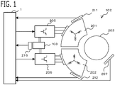
- FIG. 1 is a schematic configuration diagram of a rotary electric machine 102 and the controller 1 according to Embodiment 1.
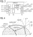
- FIG. 2 is a block diagram of the controller 1.
- the rotary electric machine 102 is one rotary electric machine which has plural sets of windings.
- the plural sets of windings is plural sets of three-phase windings provided in a stator of the rotary electric machine 102. Number of sets is two sets.
- first is referred to as “first”
- second is referred to as "second”.
- a first three-phase winding 201 and a second three-phase winding 202 are wound around the stator (armature) .
- the rotary electric machine 102 is a permanent magnet synchronous rotary electric machine in which the permanent magnet is provided in the rotor 203. Accordingly, two sets of three-phase windings 201, 202 are provided in the one stator, and the permanent magnet is provided in the one rotor 203 disposed at the radial-direction inner side of the stator.
- An axial-direction position where the first three-phase winding 201 is wound around the stator and an axial-direction position where the second three-phase winding 202 is wound around the stator are overlapped to each other. Accordingly, a rotating magnetic field generated by each set of the three-phase winding provided in the one stator acts on the permanent magnet provided in the one rotor 203, and a magnetic field generated by the permanent magnet provided in the one stator acts on each set of the three-phase winding provided in the one stator.
- a first inverter 205 which converts DC power supplied from a DC power source 103 into AC power and supplies to the first three-phase winding 201, and a second inverter 206 which converts DC power supplied from the DC power source 103 into AC power and supplies to the second three-phase winding 202 are provided.
- Each of the first and the second inverters 205, 206 is provided with a plurality of switching devices.
- Each set of the inverter is provided with three sets of a series circuit where a positive electrode side switching device connected to the positive electrode terminal of the DC power source 103 and a negative electrode side switching device connected to the negative electrode terminal of the DC power source 103 are connected in series, corresponding to respective phase of the three-phase winding.
- a connection node of two switching devices in each series circuit is connected to the winding of the corresponding phase.
- MOSFET Metal Oxide Semiconductor Field Effect Transistor
- IGBT Insulated Gate Bipolar Transistor
- a gate terminal of each switching device is connected to the controller 1 via a gate drive circuit and the like. Accordingly, each switching device is turned on or off by first switching control signal or second switching control signal outputted from the controller 1.
- An electricity accumulation device such as a lead battery and a lithium ion battery, is used for the DC power source 103.
- a DC-DC converter which is a DC electric power converter which steps up or steps down the DC voltage may be provided in the DC power source 103.
- a first current sensor 211 for detecting current which flows into the first three-phase winding 201 and a second current sensor for detecting current which flows into the second three-phase winding 202 are provided. Output signals of the first and the second current sensors 211, 212 are inputted into the controller 1. In the present embodiment, the first and the second current sensors 211, 212 are provided on each phase wire which connects the series circuit of the switching devices and the winding.
- the rotary electric machine 102 is provided with a rotation angle sensor 207, such as a resolver and a rotary encoder, for detecting a rotational angle (magnetic pole position) of the rotor 203.
- An output signal of the rotation angle sensor 207 is inputted into the controller 1.
- a voltage sensor 216 for detecting a DC power voltage VB of the DC power source 103 supplied to the first and the second inverters 205, 206 is provided.
- An output signal of the voltage sensor 216 is inputted into the controller 1.
- the rotary electric machine 102 and the controller 1 are mounted on a vehicle .
- a rotary shaft of the rotary electric machine 102 is connected to a crankshaft of an internal combustion engine via a shaft or a pulley and belt mechanism.
- the rotary electric machine 102 has a function as a motor to start or assist the internal combustion engine, and has a function as a generator which generates electricity using the driving force of the internal combustion engine.
- the controller 1 controls the rotary electric machine 102 via the switching devices of the first and the second inverters 205, 206.
- the controller 1 is provided with functional parts of a current detection unit 30, a rotation information detection unit 31, a power source voltage detection unit 32, a current command calculation unit 33, a voltage command calculation unit 34, a switching control unit 35, a voltage control value calculation unit 36, and the like, mentioned below.
- Each function of the controller 1 is realized by processing circuits provided in the controller 1. Specifically, as shown in FIG.
- the controller 1 is provided with, as a processing circuit, an arithmetic processor (computer) 90 such as a CPU (Central Processing Unit), storage apparatuses 91 that exchange data with the arithmetic processor 90, an input circuit 92 that inputs external signals to the arithmetic processor 90, an output circuit 93 that outputs signals from the arithmetic processor 90 to the outside, and the like.
- arithmetic processor computer
- CPU Central Processing Unit
- ASIC Application Specific Integrated Circuit
- IC Integrated Circuit
- DSP Digital Signal Processor
- FPGA Field Programmable Gate Array
- various kinds of logical circuits various kinds of signal processing circuits, and the like
- arithmetic processor 90 a plurality of the same type ones or the different type ones may be provided, and each processing may be shared and executed.
- a RAM Random Access Memory
- ROM Read Only Memory
- the input circuit 92 is connected with various kinds of sensors and switches such as the current sensors 211, 212, the rotation angle sensor 207, and the voltage sensor 216, and is provided with A/D converter and the like for inputting output signals from the sensors and the switches to the arithmetic processor 90.
- the output circuit 93 is connected with electric loads such as a gate drive circuit which drive on and off of the switching devices of the first and the second inverters 205, 206, and is provided with driving circuit and the like for outputting a control signal from the arithmetic processor 90.
- the arithmetic processor 90 runs software items (programs) stored in the storage apparatus 91 such as a ROM and collaborates with other hardware devices in the controller 1, such as the storage apparatus 91, the input circuit 92, and the output circuit 93, so that the respective functions of the control units 30 to 36 provided in the controller 1 are realized.
- Setting data items such as an upper limit value Vmax, a lower limit value Vmin, a maximum voltage utilization factor, and map data to be utilized in the control units 30 to 36 are stored, as part of software items (programs), in the storage apparatus 91 such as a ROM.
- Each function of the controller 1 will be described in detail below.
- the current detection unit 30 detects first three-phase currents Iu1, Iv1, Iw1 which flow into the first three-phase winding 201, based on the output signal of the first current sensor 211, and detects second three-phase currents Iu2, Iv2, Iw2 which flow into the second three-phase winding 202, based on the output signal of the second current sensor 212.
- the rotation information detection unit 31 detects a rotational angle ⁇ (a magnetic pole position ⁇ ) and a rotational speed ⁇ of the rotator 203. In the present embodiment, the rotation information detection unit 31 detects the rotational angle ⁇ (the magnetic pole position ⁇ ) and the rotational speed ⁇ based on the output voltage of the rotation angle sensor 207.
- the power source voltage detection unit 32 detects a DC power voltage VB of the DC power source 103. In the present embodiment, the power source voltage detection unit 32 detects the DC power voltage VB based on the output voltage of the voltage sensor 216.
- the current command calculation unit 33 calculates the current command value flowing to the winding, and changes each set of the current command value based on a common voltage control value Vrev described below.
- the current command calculation unit 33 calculates a d-axis current command value and a q-axis current command value which expressed each set of the current command value in a dq-axis rotating coordinate system.
- the dq-axis rotating system consists of a d-axis defined in the magnetic pole position of the rotor 203 (direction of the N pole of magnet) and a q-axis defined in the direction advanced to d-axis by 90 degrees in an electrical angle, and which is the two-axis rotating coordinate system which rotates synchronizing with rotation of the rotor 203 in the electrical angle.
- the current command calculation unit 33 calculates a first d-axis current command value Idref1 and a first q-axis current command value Iqref1 for the first three-phase winding 201, and calculates a second d-axis current command value Idref2 and a second q-axis current command value Iqref2 for the second three-phase winding 202.
- the current command calculation unit 33 calculates each set of dq-axis current command values so as to make the rotary electric machine 102 output torque of the torque command value Tref.
- the torque command value Tref may be calculated by the current command calculation unit 33, or may be transmitted from an external controller such as an integrated controller of vehicle.
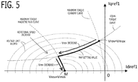
- the maximum torque current control is a control method which calculates the dq-axis current command values which maximizes a generated torque for the same current. As the torque command value Tref increases from 0, the q-axis current command value increases from 0 and the d-axis current command value decreases from 0, on the maximum torque current curve.
- the dq-axis current command values are calculated according to concept of the magnetic flux weakening control.
- the torque command value Tref increases, the dq-axis current command value changes on the voltage limit ellipse in a direction of decreasing the d-axis current command value.
- the voltage limit ellipse is a locus of the dq-axis current command values where terminal voltage (induced voltage) of the three-phase winding becomes equal to a voltage limiting value which is set less than or equal to the DC power voltage VB.
- the dq-axis current command values cannot be set outside of the voltage limit ellipse.
- the dq-axis current command values When the dq-axis current command values reach a maximum torque magnetic flux curve, the dq-axis current command values are calculated according to concept of the maximum torque magnetic flux control.
- the maximum torque magnetic flux control is a control method which calculates the dq-axis current command values which minimizes an interlinkage flux for the same torque. In the concept of the maximum torque magnetic flux control, an intersection point of the voltage limit ellipse and the maximum torque magnetic flux curve is calculated as the dq-axis current command values.
- the current command calculation unit 33 calculates first dq-axis current command values Idref1, Iqref1, and second dq-axis current command values Idref2, Iqref2, based on the torque command value Tref and the common voltage control value Vrev. Specifically, by referring to a first map data in which a relationship among the torque command value Tref, the common voltage control value Vrev, and the first dq-axis current command values Idref1, Iqref1 are preliminarily set, the current command calculation unit 33 calculates the first dq-axis current command values Idref1, Iqref1 corresponding to the present torque command value Tref and the present common voltage control value Vrev.
- the current command calculation unit 33 calculates the second dq-axis current command values Idref2, Iqref2 corresponding to the present torque command value Tref and the present common voltage control value Vrev.
- FIG. 5 shows an example of setting values of the first and the second map data when the torque command value Tref is a certain constant value.
- the common voltage control value Vrev is the upper limit value Vmax (in this example, 0)
- the dq-axis current command values are set to an intersection point of the maximum torque current curve and the equal torque curve.
- the common voltage control value Vrev decreases from the upper limit value Vmax
- the dq-axis current command values are set so as to change on the equal torque curve to the lower left.
- the induced voltage (terminal voltage) of the three-phase winding decreases, and the required DC voltage described below decreases.
- the current command calculation unit 33 changes the dq-axis current command values to a side where the required DC voltage decreases.
- the current command calculation unit 33 changes the dq-axis current command values to a side where the required DC voltage increases.
- the dq-axis current command values change on the equal torque curve to the lower left and reach the maximum torque magnetic flux curve
- the common voltage control value Vrev decreases
- the dq-axis current command values are set so as to change on the maximum torque magnetic flux curve to the lower right until it reaches the M point.
- the common voltage control value Vrev becomes the lower limit value Vmin.
- Data like the example of FIG. 5 is set to each of a plurality of the torque command values Tref.
- the torque command Tref is a negative value
- the q-axis current command value becomes a negative value, but the change tendency of the current command value is similar to that of the case where the torque command Tref is a positive value. If electromagnetic characteristics have characteristics reversed between positive and negative of the q-axis current, data reversed between positive and negative of the q-axis of FIG. 5 may be set.
- the maximum torque current control, and the magnetic flux weakening control or the maximum torque magnetic flux control can be switched automatically, and in the magnetic flux weakening control or the maximum torque magnetic flux control, the dq-axis current command values can be automatically coincided with the intersection point of the voltage limit ellipse, and the equal torque curve or the maximum torque magnetic flux curve.
- the current command calculation unit 33 calculates the first and the second dq-axis current command values with reference to the first and the second map data which are close to the present rotational speed ⁇ .
- the voltage command calculation unit 34 calculates the voltage command value applied to winding, based on the current command value and the current detection value.
- the voltage command calculation unit 34 calculates the voltage command values of three-phase AC applied to the three-phase winding, based on the current command value and the current detection value.
- the voltage command calculation unit 34 changes the dq-axis voltage command values so that the dq-axis current detection values which expressed the current detection values of the three-phase winding in the dq-axis rotating coordinate system approaches the dq-axis current command values, and converts the dq-axis voltage command values into the voltage command values of three-phase AC.
- the voltage command calculation unit 34 calculates a first d-axis current detection value Id1 and a first q-axis current detection value Iq1, by performing a three-phase/two-phase conversion and a rotating coordinate conversion to the first three-phase currents detection values Iu1, Iv1, Iw1, based on the magnetic pole position ⁇ . Similarly, the voltage command calculation unit 34 calculates a second d-axis current detection value Id2 and a second q-axis current detection value Iq2, by performing the three-phase/two-phase conversion and the rotating coordinate conversion to the second three-phase currents detection values Iu2, Iv2, Iw2, based on the magnetic pole position ⁇ .
- the voltage command calculation unit 34 changes a first d-axis voltage command value Vdref1 and a first q-axis voltage command value Vqref1 by PI control and the like so that the first dq-axis current detection values Id1, Iq1 approach the first dq-axis current command values Idref1, Iqref1.
- Vdref 1 Vqref 1 Kpd + Kid 1 s Idref 1 ⁇ Id 1 Kpq + Kid 1 s Iqref 1 ⁇ Iq 1
- the voltage command calculation unit 34 changes a second d-axis voltage command value Vdref2 and a second q-axis voltage command value Vqref2 by PI control and the like so that the second dq-axis current detection values Id2, Iq2 approach the second dq-axis current command values Idref2, Iqref2 .
- Kpd is a d-axis proportional gain
- Kpq is a q-axis proportional gain
- Kid is a d-axis integral gain
- Kiq is a q-axis integral gain
- s is a Laplace operator.
- the voltage command calculation unit 34 calculates first voltage command values Vuref1, Vvref1, Vwref1 of three-phase AC, by performing a fixed coordinate conversion and a two-phase/three-phase conversion to the first dq-axis voltage command values Vdref1, Vqref1, based on the magnetic pole position ⁇ . Similarly, the voltage command calculation unit 34 calculates second voltage command values Vuref2, Vvref2, Vwref2 of three-phase AC, by performing the fixed coordinate conversion and the two-phase/three-phase conversion to the second dq-axis voltage command values Vdref2, Vqref2, based on the magnetic pole position ⁇ .
- the switching control unit 35 For each set, the switching control unit 35 performs PWM (Pulse Width Modulation) control which controls on/off the switching devices, based on the voltage command value.
- PWM Pulse Width Modulation
- the switching control unit 35 compares each of the first voltage command values Vuref1, Vvref1, Vwref1 of three-phase AC with a carrier wave (a triangular wave) which have an amplitude of the DC power voltage VB and vibrates at a carrier frequency; and turns on the switching control signal when the AC voltage command value exceeds the carrier wave, and turns off the switching control signal when the AC voltage command value is below the carrier wave.
- the switching control unit 35 outputs each switching control signal to the gate terminal of the corresponding switching device of the first inverter 205.
- the switching control unit 35 compares each of the second voltage command values Vuref2, Vvref2, Vwref2 of three-phase AC with the carrier wave, and turns on or turns off the switching control signal.
- the switching control unit 35 outputs each switching control signal to the gate terminal of the corresponding switching device of the second inverter 206.
- the required DC voltage which is the minimum DC power voltage required for applying a voltage of the voltage command value to the three-phase winding also increases. If the required DC voltage exceeds the actual DC power voltage VB, it becomes impossible to flow current through the three-phase winding normally, and torque fluctuation occurs. Therefore, when the required DC voltage exceeds the DC power voltage VB, the voltage command value and the required current voltage are lowered by operating the current command value so that the induced voltage generated in the three-phase winding decreases.
- the required DC voltage exists for each set of the three-phase winding. Therefore, it is necessary to prevent all sets of the required DC voltage from exceeding the DC power voltage VB.
- the current command value is individually operated for each set so that each set of the required DC voltage does not exceed the DC power voltage VB, combination pattern of control state of each set of the three-phase winding increases significantly, it is necessary to secure operation of all patterns, and control design becomes complicated. If the current command value is individually operated for each set so that each set of the required DC voltage does not exceed the DC power voltage VB, interaction of the current command value among sets due to interaction of the magnetic coupling among sets occurs. Therefore, it is not easy to secure stability of operation behavior of the current command value.
- the voltage control value calculation unit 36 calculates, for each set, a required DC voltage which is a minimum DC power voltage required for applying a voltage according to the voltage command value to the winding, based on the voltage command value, and calculates one common required DC voltage Vnecm which is common to all sets, based on all sets of the required DC voltages. Then, the voltage control value calculation unit 36 changes a common voltage control value Vrev so that the common required DC voltage Vnecm approaches the DC power voltage VB.
- each set of the required DC voltage set can be prevented from exceeding the DC power voltage VB, current is normally flowed through each set of the three-phase winding, and occurrence of torque fluctuation can be suppressed.
- the voltage control value calculation unit 36 calculates a line voltage effective value of the voltage command values of three-phase AC, and calculates the required DC voltage by dividing the line voltage effective value of the voltage command values of three-phase AC by a preliminarily set maximum voltage utilization factor.
- the voltage control value calculation unit 36 calculates a line voltage effective value of the first three-phase AC voltage command values, based on the first dq-axis voltage command values Vdref1, Vqref1, and calculates a first required DC voltage Vne1 by dividing the line voltage effective value by a preliminarily set first maximum voltage utilization factor Rmx1.
- Vne 1 Vdref 1 2 + Vqref 1 2 Rmx 1
- the voltage control value calculation unit 36 calculates, for second set, a line voltage effective value of the second three-phase AC voltage command values, based on the second dq-axis voltage command values Vdref2, Vqref2, and calculates a second required DC voltage Vne2 by dividing the line voltage effective value by a preliminarily set second maximum voltage utilization factor Rmx2.
- Vne 2 Vdref 2 2 + Vqref 2 2 Rmx 2
- the first and the second maximum voltage utilization factors Rmx1, Rmx2 are preliminarily set to values corresponding to the PWM control method in the switching control unit 35.
- the maximum voltage utilization factor is set to 0.612.
- the overmodulation PWM control third harmonic wave injection, space vector modulation, two-phase modulation, and the like
- the maximum voltage utilization factor is set to 0.707.
- the maximum voltage utilization factor may be set to a value smaller than 0.612 or 0.707.
- the voltage control value calculation unit 36 calculates a maximum value in all sets of the required DC voltages, as the common required DC voltage Vnecm. Specifically, as shown in an equation (5), the voltage control value calculation unit 36 calculates a maximum value in the first required DC voltage Vne1 and the second required DC voltage Vne2, as the common required DC voltage Vnecm.
- MAX (A, B) is a function which outputs a larger value between A and B.
- Vnecm MAX Vne 1 , Vne 2
- the required DC voltage of set which becomes the maximum value can be prevented from exceeding the DC power voltage VB, and the required DC voltage of sets other than the maximum value can also be limited to less than or equal to the DC power voltage VB.
- the dq-axis current command values can be changed on the voltage limit ellipse.
- the voltage control value calculation unit 36 changes the common voltage control value Vrev so that the common required DC voltage Vnecm approaches the DC power voltage VB.
- the voltage control value calculation unit 36 changes the common voltage control value Vrev by PI control and the like, based on a deviation between the common required DC voltage Vnecm and the DC power voltage VB.
- Kp is a proportional gain of a positive value
- Ki is an integral gain of a positive value.
- Vrev Kp + Ki 1 s VB ⁇ Vnecm
- the current command calculation unit 33 changes the dq-axis current command values so that the induced voltage (terminal voltage) of the three-phase winding decreases and the required DC voltage decreases in region of the magnetic flux weakening control and the maximum torque magnetic flux control. Consequently, the common required DC voltage Vnecm decreases and approaches the DC power voltage VB.
- the current command calculation unit 33 changes the dq-axis current command values so that the induced voltage (terminal voltage) of the three-phase winding increases and the required DC voltage increases in region of the magnetic flux weakening control and the maximum torque magnetic flux control. Consequently, the common required DC voltage Vnecm increases and approaches the DC power voltage VB.
- the voltage control value calculation unit 36 upper and lower limits the common voltage control value Vrev by a upper limit value Vmax and a lower limit value Vmin which are preliminarily set.
- the upper limit value Vmax is set to a value (in this example, 0) of the common voltage control value Vrev when the dq-axis current command values become values on the maximum torque current curve (intersection point (a) of FIG. 4 ).
- the lower limit value Vmin is set to a value (in this example, a predetermined value smaller than 0) of the common voltage control value Vrev when the dq-axis current command values become the M point.
- the voltage control value calculation unit 36 When upper-limiting the common voltage control value Vrev by the upper limit value Vmax or lower-limiting by the lower limit value Vmin, the voltage control value calculation unit 36 performs anti wind-up processing that does not change the common voltage control value Vrev. For example, when upper-limiting or lower-limiting the common voltage control value Vrev, the voltage control value calculation unit 36 stops update of the integral value of PI control of the equation (6).
- the deviation is calculated by (VB - Vnecm) in the equation (6)
- the deviation may be calculated by (Vnecm - VB).
- change direction of the common voltage control value Vrev is reversed
- the upper limit value Vmax corresponds to the M point
- the lower limit value Vmin corresponds to the point on the maximum torque current curve.
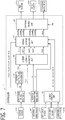
- FIG. 6 is a schematic configuration diagram of a rotary electric machine 102 and the controller 1 according to the present embodiment; and FIG. 7 is a block diagram of the controller 1.
- a field winding 213 is provided in the rotor 203 of the rotary electric machine 102, and the controller 1 controls voltage application to the field winding 213.
- the plural sets of windings which the rotary electric machine 102 has are 1 set or plural sets (in this example, two sets) of the three-phase windings provided in the stator, and 1 set of the field winding 213 provided in the rotor 203.
- the rotary electric machine 102 is a winding field synchronous rotary electric machine in which the first three-phase winding 201 and the second three-phase winding 202 are provided in the stator, and the field winding 213 is provided in the rotor 203.
- the first three-phase winding 201 is first set of winding
- the second three-phase winding 202 is second set of winding
- the field winding 213 is third set of winding.
- the field winding driving circuit 215 which controls supply of the DC power to the field winding 213 is provided.
- the field winding driving circuit 215 has a switching device. On the positive pole wire which connects the DC power source 103 and the field winding 213, the switching device of the field winding driving circuit 215 is provided, and turns on and off connection between the DC power source 103 and the field winding 213.
- the switching device of the field winding driving circuit 215 is turned on or turned off by a switching control signal of field winding outputted from the controller 1.
- a current sensor 214 of field winding for detecting a current which flows into the field winding 213 is provided.
- An output signal of the current sensor 214 of field winding is inputted into the controller 1.
- the current detection unit 30 detects a field current If which flows into the field winding 213 based on the output signal of the current sensor 214 of field winding.
- the current command calculation unit 33 calculates the current command value flowing to the winding, and changes each set of the current command value based on the common voltage control value Vrev.
- the current command calculation unit 33 calculates a field current command value Ifref which is a current command value which flows into the field winding.
- the current command calculation unit 33 calculates the field current command value Ifref based on the torque command value Tref and the common voltage control value Vrev.
- the current command calculation unit 33 calculates the field current command value Ifref corresponding to the present torque command value Tref and the present common voltage control value Vrev.
- the map data of field winding is provided for each of a plurality of the rotational speeds ⁇ , and the current command calculation unit 33 calculates the field current command value Ifref by referring to the map data of field winding close to the present rotational speed ⁇ .
- the current command calculation unit 33 calculates the first dq-axis current command values Idref1, Iqref1, and the second dq-axis current command values Idref2, Iqref2, based on the torque command value Tref and the common voltage control value Vrev. Specifically, by referring to the first map data in which a relationship among the torque command value Tref, the common voltage control value Vrev, and the first dq-axis current command values Idref1, Iqref1 are preliminarily set, the current command calculation unit 33 calculates the first dq-axis current command values Idref1, Iqref1 corresponding to the present torque command value Tref and the present common voltage control value Vrev.
- the current command calculation unit 33 calculates the second dq-axis current command values Idref2, Iqref2 corresponding to the present torque command value Tref and the present common voltage control value Vrev.
- the first and the second map data are provided for each of a plurality of the rotational speeds ⁇ , the current command calculation unit 33 calculates the first and the second dq-axis current command values by referring to the first and the second map data which are close to the present rotational speed ⁇ .
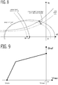
- the interlinkage flux (field current) of the field winding 213 changes according to operating condition of the torque command value Tref, the common voltage control value Vrev, and the rotational speed ⁇ . As shown in FIG. 8 , when the interlinkage flux (field current) of the field winding 213 decreases, the M point (center point) of the voltage limit ellipse moves to the positive direction on the d-axis, the voltage limit ellipse spreads and the equal torque curve shifts to the up side.
- the first and the second map data of the dq-axis current command values are set based on the torque command value Tref, the common voltage control value Vrev, and the rotational speed ⁇ as similar to the map data of the field current command value Ifref, these are preliminarily set so as to correspond to moving of the M point of the voltage limit ellipse, expansion and reduction of the voltage limit ellipse, shift of the equal torque curve, change of the maximum torque magnetic flux curve, and change of the maximum torque current curve, which are caused by change of the field current command value Ifref.
- FIG. 9 shows an example of setting values of the map data of field winding when the torque command value Tref is a certain constant value.
- the common voltage control value Vrev is the upper limit value Vmax (in this example, 0)
- the field current command value Ifref is set to a value according to the torque command value Tref.
- the common voltage control value Vrev becomes smaller than the upper limit value Vmax, it becomes a region of the magnetic flux weakening control; and as the common voltage control value Vrev decreases from the upper limit value Vmax, the field current command value Ifref decreases and the magnetic flux of field winding is weakened.
- the common voltage control value Vrev When the common voltage control value Vrev further decreases, it becomes a region of the maximum torque magnetic flux control; as the common voltage control value Vrev decreases, the field current command value Ifref decreases with gradient steeper than region of the magnetic flux weakening control; and when the common voltage control value Vrev reaches the lower limit value Vmin, the field current command value Ifref is set to 0.
- FIG. 10 shows an example of setting values of the first or the second map data when the torque command value Tref and the rotational speed ⁇ are certain constant values and the field current command value Ifref is changed as shown in FIG. 9 with respect to change of the common voltage control value Vrev.
- the common voltage control value Vrev is the upper limit value Vmax (in this example, 0)
- the dq-axis current command values are set to the intersection point (a) between the maximum torque current curve and the equal torque curve.
- the common voltage control value Vrev becomes smaller than the upper limit value Vmax, it becomes a region of the magnetic flux weakening control; and as the common voltage control value Vrev decreases from the upper limit value Vmax, the field current command value Ifref decreases and then the equal torque curve shifts to the up side. Accordingly, the dq-axis current command values are set to change to left side on the equal torque curve which is shifted to the up side as the common voltage control value Vrev decreases from the upper limit value Vmax. Therefore, magnetic flux weakening by decrease in the d-axis current is also performed.
- the common voltage control value Vrev When the common voltage control value Vrev further decreases, it becomes a region of the maximum torque magnetic flux control; and as the common voltage control value Vrev decreases, the field current command value Ifref decreases to 0 gradually, and then the M point shifts to right side, and the maximum torque magnetic flux curve also shifts to right side. Even when the field current command value Ifref becomes the lower limit value Vmin and the field current command value Ifref becomes 0, magnetic flux remains in the iron core of the rotor 203, and then the M point becomes a predetermined position on the left side of 0 point. Accordingly, the dq-axis current command values are set to change to the lower right toward the M point when the field current command value Ifref is 0, on the maximum torque magnetic flux curve which shifts to right side as the common voltage control value Vrev decreases.
- the current command calculation unit 33 sets the field current command value Ifref to 0, and sets each set of the current command value of the three-phase winding (in this example, the dq-axis current command values) to a value corresponding to the center point (M point) of the voltage limit ellipse when the field winding current is 0.
- the voltage command calculation unit 34 calculates the voltage command value applied to winding, based on the current command value and the current detection value. In the present embodiment, the voltage command calculation unit 34 calculates, for the field winding 213, a field voltage command value Vfref of one-phase DC applied to the field winding 213, based on the field current command value Ifref and the field current detection value If. In the present embodiment, the voltage command calculation unit 34 changes the field voltage command value Vfref so that the field current detection value If approaches the field current command value Ifref.
- the voltage command calculation unit 34 changes the field voltage command value Vfref by PI control and the like, based on a deviation between the field current detection value If and the field current command value Ifref.
- Kpf is a proportional gain
- Kif is an integral gain.
- Vfref Kpf + Kif 1 s Ifref ⁇ If
- the voltage command calculation unit 34 calculates, for each set of the three-phase winding, the voltage command values of the three-phase AC applied to the three-phase winding, based on the current command value and the current detection value. As similar to Embodiment 1, for each set, the voltage command calculation unit 34 changes the dq-axis voltage command values so that the dq-axis current detection values which expressed the current detection values of the three-phase winding in the dq-axis rotating coordinate system approaches the dq-axis current command values, and converts the dq-axis voltage command values into the voltage command values of three-phase AC.
- the switching control unit 35 For each set, the switching control unit 35 performs PWM control which controls on/off the switching devices, based on the voltage command value. In the present embodiment, the switching control unit 35 generates a switching control signal that turns on and off at a duty ratio (Vfref / VB) obtained by dividing the field voltage command value Vfref by the DC power voltage VB, and outputs the switching control signal to the gate terminal of the switching device of the field winding driving circuit 215.
- Vfref / VB a duty ratio
- the switching control unit 35 compares each of the voltage command values of three-phase AC with the carrier wave, generates the switching control signal that turns on and off based on the comparison result, and outputs each switching control signal to the gate terminal of the switching device of the corresponding inverter.
- the voltage control value calculation unit 36 calculates, for each set, the required DC voltage which is a minimum DC power voltage required for applying a voltage according to the voltage command value to the winding, based on the voltage command value and the DC power voltage VB, and calculates one common required DC voltage Vnecm which is common to all sets, based on all sets of the required DC voltages. Then, the voltage control value calculation unit 36 changes the common voltage control value Vrev so that the common required DC voltage Vnecm approaches the DC power voltage VB.
- the voltage control value calculation unit 36 calculates, for the field winding 213, a required DC voltage Vnef of field winding by dividing the field voltage command value Vfref by a preliminarily set maximum voltage utilization factor Rmxf of field winding.
- Vnef Vfref Rmxf
- the maximum voltage utilization factor Rmxf of field winding is preliminarily set to 1, for example. In order to lower the actually used DC voltage rather than the DC power voltage VB, the maximum voltage utilization factor Rmxf of field winding may be set to a value smaller than 1.
- the voltage control value calculation unit 36 calculates a line voltage effective value of the voltage command values of three-phase AC, and calculates the required DC voltage by dividing the line voltage effective value of the voltage command values of three-phase AC by a preliminarily set maximum voltage utilization factor.
- the voltage control value calculation unit 36 calculates a maximum value in all sets of the required DC voltages, as the common required DC voltage Vnecm. Specifically, as shown in an equation (10), the voltage control value calculation unit 36 calculates a maximum value in the first required DC voltage Vne1, the second required DC voltage Vne2, and the required DC voltage Vnef of field winding, as the common required DC voltage Vnecm.
- MAX (A, B, C) is a function which outputs the largest value among A, B, and C.
- Vnecm MAX Vne 1 , Vne 2 , Vnef
- the voltage control value calculation unit 36 changes the common voltage control value Vrev so that the common required DC voltage Vnecm approaches the DC power voltage VB.
- the current command calculation unit 33 changes the dq-axis current command values and the field current command value Ifref so that the induced voltage (terminal voltage) of the three-phase winding decreases and the required DC voltage of the three-phase winding decreases in region of the magnetic flux weakening control and the maximum torque magnetic flux control. Consequently, the common required DC voltage Vnecm decreases and approaches the DC power voltage VB.
- the current command calculation unit 33 decreases the field current command value Ifref, and decreases the required DC voltage Vnef of field winding.
- the dq-axis current command values are also changed by decrease of the common voltage control value Vrev in conjunction with each other, and can be corresponded to the changed field current command value Ifref.
- the field current command value Ifref and each set of the current command value of the three-phase winding are changed by the common voltage control value Vrev in conjunction with each other, the required DC voltage Vnef of field winding and each set of the required DC voltage of the three-phase winding can be prevented from exceeding the DC power voltage VB, and the rotary electric machine can be operated appropriately.
Landscapes
- Engineering & Computer Science (AREA)
- Power Engineering (AREA)
- Control Of Ac Motors In General (AREA)
Claims (9)
- Eine Steuerung (1) einer elektrische Drehmaschine, die eine elektrische Drehmaschine (102), die mehrere Sätze von Wicklungen hat, über Schaltvorrichtungen steuert, wobei die Steuerung (1) der elektrischen Drehmaschine Folgendes umfasst:eine Stromerfassungseinheit (30), die für jeden Satz konfiguriert ist, einen in die Wicklung fließenden Strom zu erfassen;eine Strombefehlsberechnungseinheit (33), die für jeden Satz konfiguriert ist, einen Strombefehlswert zu berechnen, der in die Wicklung fließt;eine Spannungsbefehlsberechnungseinheit (34), die für jeden Satz konfiguriert ist, einen an die Wicklung angelegten Spannungsbefehlswert auf der Grundlage des Strombefehlswertes und eines Stromerfassungswertes zu berechnen;eine Schaltsteuereinheit (35), die für jeden Satz konfiguriert ist, die Schaltvorrichtung basierend auf dem Spannungsbefehlswert ein-/auszuschalten; und gekennzeichnet durcheine Spannungssteuerwertberechnungseinheit (36), die konfiguriert ist, für jeden Satz eine erforderliche Gleichspannung zu berechnen, die eine minimale Leistungsgleichspannung ist, die zum Anlegen einer Spannung gemäß dem Spannungsbefehlswert an die Wicklung erforderlich ist, basierend auf dem Spannungsbefehlswert, konfiguriert ist, eine gemeinsame erforderliche Gleichspannung (Vnecm) zu berechnen, die allen Sätzen gemeinsam ist, basierend auf allen Sätzen der erforderlichen Gleichspannungen, und konfiguriert ist, einen gemeinsamen Spannungssteuerwert (Vrev) zu ändern, so dass die gemeinsame erforderliche Gleichspannung (Vnecm) sich einer Leistungsgleichspannung (VB) nähert, die den Schaltvorrichtungen zugeführt wird,wobei die Strombefehlsberechnungseinheit (33) konfiguriert ist, jeden Satz des Strombefehlswertes basierend auf dem gemeinsamen Spannungssteuerwert (Vrev) zu ändern.
- Die Steuerung (1) einer elektrischen Drehmaschine nach Anspruch 1, wobei die Spannungssteuerwertberechnungseinheit (36) konfiguriert ist, einen maximalen Wert in allen Sätzen der erforderlichen Gleichspannungen als die gemeinsame erforderliche Gleichspannung (Vnecm) zu berechnen.
- Die Steuerung (1) einer elektrischen Drehmaschine nach Anspruch 1 oder 2, wobei die mehreren Sätze von Wicklungen mehrere Sätze von dreiphasigen Wicklungen sind, die in einem Stator der elektrischen Drehmaschine (102) vorgesehen sind.
- Die Steuerung (1) einer elektrischen Drehmaschine nach Anspruch 3, wobei die Spannungsbefehlsberechnungseinheit (34) für jeden Satz konfiguriert ist, die Spannungsbefehlswerte des an die Drehstromwicklung angelegten Drehstroms auf der Grundlage des Strombefehlswertes und des Stromerfassungswertes zu berechnen,
wobei die Spannungssteuerwertberechnungseinheit (36) für jeden Satz konfiguriert ist, einen Netzspannungseffektivwert der Spannungsbefehlswerte von Dreiphasen-Wechselstrom zu berechnen, und konfiguriert ist, die erforderliche Gleichspannung zu berechnen, indem der Netzspannungseffektivwert der Spannungsbefehlswerte von Dreiphasen-Wechselstrom durch einen vorläufig eingestellten maximalen Spannungsausnutzungsfaktor geteilt wird. - Die Steuerung (1) einer elektrischen Drehmaschine nach Anspruch 1 oder 2, wobei die mehreren Sätze von Wicklungen ein Satz oder mehrere Sätze von dreiphasigen Wicklungen sind, die in einem Stator der elektrischen Drehmaschine (102) vorgesehen sind, und ein Satz von Feldwicklungen, die in einem Rotor der elektrischen Drehmaschine (102) vorgesehen sind.
- Die Steuerung (1) einer elektrischen Drehmaschine nach Anspruch 5, wobei die Spannungsbefehlsberechnungseinheit (34) konfiguriert ist, für die Feldwicklung den Spannungsbefehlswert (Vfref) von einphasigem Gleichstrom, der an die Feldwicklung angelegt wird, basierend auf dem Strombefehlswert (Ifref) und dem Stromerfassungswert (If) zu berechnen, und für jeden Satz der dreiphasigen Wicklung die Spannungsbefehlswerte von dreiphasigem Wechselstrom, der an die dreiphasige Wicklung angelegt wird, basierend auf dem Strombefehlswert und dem Stromerfassungswert zu berechnen,
wobei die Spannungssteuerwertberechnungseinheit (36) konfiguriert ist, für die Feldwicklung die erforderliche Gleichspannung (Vnef) zu berechnen, indem der Spannungsbefehlswert (Vfref) des einphasigen Gleichstroms durch einen vorläufig eingestellten maximalen Spannungsausnutzungsfaktor (Rmxf) der Feldwicklung dividiert wird, konfiguriert ist, für jeden Satz der dreiphasigen Wicklung zu berechnen für jeden Satz der dreiphasigen Wicklung einen Netzspannungseffektivwert der Spannungsbefehlswerte des dreiphasigen Wechselstroms zu berechnen, und konfiguriert ist, für jeden Satz der dreiphasigen Wicklung die erforderliche Gleichspannung zu berechnen, indem der Netzspannungseffektivwert der Spannungsbefehlswerte des dreiphasigen Wechselstroms durch einen vorläufig eingestellten maximalen Spannungsausnutzungsfaktor dividiert wird. - Die Steuerung (1) einer elektrischen Drehmaschine nach Anspruch 6, wobei die Spannungssteuerwertberechnungseinheit (36) konfiguriert ist, den gemeinsamen Spannungssteuerwert (Vrev) durch einen vorläufig eingestellten unteren Grenzwert (Vmin) nach unten zu begrenzen,wobei, wenn der gemeinsame Spannungssteuerwert (Vrev) konfiguriert ist, zu sinken, die Strombefehlsberechnungseinheit (33) konfiguriert ist, jeden Satz des Strombefehlswertes zu einer Seite zu ändern, wo jeder Satz der erforderlichen Gleichspannung sinkt; undwenn der gemeinsame Spannungssteuerwert (Vrev) durch den unteren Grenzwert (Vmin) nach unten begrenzt ist, die Strombefehlsberechnungseinheit (33) konfiguriert ist, den Strombefehlswert (Ifref) der Feldwicklung auf 0 zu setzen und jeden Satz des Strombefehlswertes der dreiphasigen Wicklung auf einen Wert zu setzen, der einem Mittelpunkt einer Spannungsgrenzellipse entspricht, wenn der Strom der Feldwicklung 0 ist.
- Die Steuerung (1) einer elektrischen Drehmaschine nach einem der Ansprüche 1 bis 7, wobei die Spannungssteuerwertberechnungseinheit (36) konfiguriert ist, den gemeinsamen Spannungssteuerwert (Vrev) nach oben und unten zu begrenzen, indem ein oberer Grenzwert (Vmax) und ein unterer Grenzwert (Vmin) im Voraus festgelegt werden; und
wenn der gemeinsame Spannungssteuerwert (Vrev) durch den oberen Grenzwert (Vmax) nach oben begrenzt wird oder durch den unteren Grenzwert (Vmin) nach unten begrenzt wird, ist die Spannungssteuerwertberechnungseinheit (36) konfiguriert, eine Anti-Wind-up-Verarbeitung durchzuführen, die den gemeinsamen Spannungssteuerwert (Vrev) nicht ändert. - Die Steuerung (1) einer elektrischen Drehmaschine nach einem der Ansprüche 1 bis 8, wobei die Strombefehlsberechnungseinheit (33) für jeden Satz konfiguriert ist, den Strombefehlswert zu berechnen, der zumindest dem gegenwärtigen gemeinsamen Spannungssteuerwert (Vrev) entspricht, indem auf Abbildungsdaten Bezug genommen wird, in denen eine Beziehung zumindest zwischen dem gemeinsamen Spannungssteuerwert (Vrev) und dem Strombefehlswert im Voraus festgelegt ist.
Applications Claiming Priority (1)
| Application Number | Priority Date | Filing Date | Title |
|---|---|---|---|
| PCT/JP2018/000246 WO2019138454A1 (ja) | 2018-01-10 | 2018-01-10 | 回転電機の制御装置 |
Publications (3)
| Publication Number | Publication Date |
|---|---|
| EP3739746A1 EP3739746A1 (de) | 2020-11-18 |
| EP3739746A4 EP3739746A4 (de) | 2020-12-16 |
| EP3739746B1 true EP3739746B1 (de) | 2021-11-03 |
Family
ID=67219453
Family Applications (1)
| Application Number | Title | Priority Date | Filing Date |
|---|---|---|---|
| EP18899587.2A Active EP3739746B1 (de) | 2018-01-10 | 2018-01-10 | Vorrichtung zur steuerung einer elektrischen drehmaschine |
Country Status (4)
| Country | Link |
|---|---|
| US (1) | US11081998B2 (de) |
| EP (1) | EP3739746B1 (de) |
| JP (1) | JP6735937B2 (de) |
| WO (1) | WO2019138454A1 (de) |
Families Citing this family (7)
| Publication number | Priority date | Publication date | Assignee | Title |
|---|---|---|---|---|
| JP6928149B1 (ja) * | 2020-05-26 | 2021-09-01 | 三菱電機株式会社 | 交流回転電機の制御装置 |
| CN117044101A (zh) * | 2021-04-16 | 2023-11-10 | 三菱电机株式会社 | 旋转电机控制装置以及电动助力转向装置 |
| US11646682B2 (en) * | 2021-09-30 | 2023-05-09 | Rolls-Royce Corporation | Technologies for redundant shaft information feedback in multi-machine drive systems with multiple resolvers |
| US11601077B1 (en) * | 2021-09-30 | 2023-03-07 | Rolls-Royce Corporation | Technologies for redundant shaft information feedback in electric machine systems including a resolver |
| US11611304B1 (en) * | 2022-03-03 | 2023-03-21 | GM Global Technology Operations LLC | System and method for minimizing demagnetization in rotor magnets |
| WO2024194912A1 (ja) * | 2023-03-17 | 2024-09-26 | 三菱電機株式会社 | 回転機の制御装置 |
| EP4576559A1 (de) * | 2023-12-19 | 2025-06-25 | Volvo Truck Corporation | Computersystem und verfahren zur wärmeerzeugung |
Family Cites Families (11)
| Publication number | Priority date | Publication date | Assignee | Title |
|---|---|---|---|---|
| JP4749852B2 (ja) * | 2005-11-30 | 2011-08-17 | 日立オートモティブシステムズ株式会社 | モータ駆動装置及びそれを用いた自動車 |
| JP4876661B2 (ja) * | 2006-03-24 | 2012-02-15 | 株式会社デンソー | 車両用発電電動装置 |
| JP4985956B2 (ja) * | 2007-04-13 | 2012-07-25 | 本田技研工業株式会社 | 電動機の制御装置 |
| JP2012200073A (ja) | 2011-03-22 | 2012-10-18 | Aisin Aw Co Ltd | 回転電機制御装置 |
| WO2013111327A1 (ja) * | 2012-01-27 | 2013-08-01 | 三菱電機株式会社 | モータ制御装置および電動パワーステアリング装置 |
| JP5590076B2 (ja) * | 2012-07-04 | 2014-09-17 | 株式会社デンソー | 多相回転機の制御装置 |
| JP6164166B2 (ja) * | 2014-06-23 | 2017-07-19 | 株式会社デンソー | 多重巻線回転電機の制御装置 |
| WO2017141513A1 (ja) * | 2016-02-17 | 2017-08-24 | 三菱電機株式会社 | 電力変換装置 |
| WO2018012417A1 (ja) * | 2016-07-11 | 2018-01-18 | 株式会社デンソー | モータ制御装置、モータ駆動システム、及び、モータ制御方法 |
| JP7027808B2 (ja) * | 2016-11-11 | 2022-03-02 | 株式会社デンソー | 回転電機制御装置、および、これを用いた電動パワーステアリング装置 |
| JP6747329B2 (ja) * | 2017-02-10 | 2020-08-26 | 株式会社デンソー | 回転電機制御装置 |
-
2018
- 2018-01-10 WO PCT/JP2018/000246 patent/WO2019138454A1/ja not_active Ceased
- 2018-01-10 EP EP18899587.2A patent/EP3739746B1/de active Active
- 2018-01-10 US US16/761,515 patent/US11081998B2/en not_active Expired - Fee Related
- 2018-01-10 JP JP2019565099A patent/JP6735937B2/ja active Active
Also Published As
| Publication number | Publication date |
|---|---|
| US20200266748A1 (en) | 2020-08-20 |
| EP3739746A1 (de) | 2020-11-18 |
| JPWO2019138454A1 (ja) | 2020-04-02 |
| WO2019138454A1 (ja) | 2019-07-18 |
| EP3739746A4 (de) | 2020-12-16 |
| JP6735937B2 (ja) | 2020-08-05 |
| US11081998B2 (en) | 2021-08-03 |
Similar Documents
| Publication | Publication Date | Title |
|---|---|---|
| US11081998B2 (en) | Controller of rotary electric machine | |
| US7049779B2 (en) | Motor drive control apparatus, motor drive control method and program of the same | |
| JP5781785B2 (ja) | 回転電機駆動システム | |
| CN103563237B (zh) | 旋转电机控制装置 | |
| US8232753B2 (en) | Control device for electric motor drive apparatus | |
| US8390223B2 (en) | Control device for electric motor drive device | |
| US8278865B2 (en) | Control device | |
| CN102577093B (zh) | 电动机驱动装置的控制装置 | |
| US20100301788A1 (en) | Control device for electric motor drive device | |
| JP5803559B2 (ja) | 回転電機制御装置 | |
| US20140152207A1 (en) | Motor control device | |
| CN107306101B (zh) | 旋转电机的控制装置 | |
| US12278582B2 (en) | Controller for rotary machine | |
| JP6173516B1 (ja) | 電動機制御装置および電動機制御方法 | |
| JP4715576B2 (ja) | 電動駆動制御装置及び電動駆動制御方法 | |
| US12362688B2 (en) | Systems and methods for control of multi-phase machines | |
| US12381505B2 (en) | Rotating electrical machine control device | |
| CN108432120B (zh) | 旋转电机的控制装置 | |
| JP4462207B2 (ja) | 電動駆動制御装置及び電動駆動制御方法 | |
| US11323056B2 (en) | Controller for AC rotary electric machine | |
| JP2003259509A (ja) | 電動車両駆動制御装置、電動車両駆動制御方法及びそのプログラム | |
| WO2018116668A1 (ja) | モータ制御装置および電動車両 | |
| JP3920213B2 (ja) | 電動駆動制御装置、電動駆動制御方法及びそのプログラム | |
| Kim et al. | Flux-weakening control of PMSM considering inverter nonlinearity | |
| JP2014072920A (ja) | モータシステム、モータ制御装置、モータ制御プログラム、及び、モータ制御方法 |
Legal Events
| Date | Code | Title | Description |
|---|---|---|---|
| STAA | Information on the status of an ep patent application or granted ep patent |
Free format text: STATUS: THE INTERNATIONAL PUBLICATION HAS BEEN MADE |
|
| PUAI | Public reference made under article 153(3) epc to a published international application that has entered the european phase |
Free format text: ORIGINAL CODE: 0009012 |
|
| STAA | Information on the status of an ep patent application or granted ep patent |
Free format text: STATUS: REQUEST FOR EXAMINATION WAS MADE |
|
| 17P | Request for examination filed |
Effective date: 20200508 |
|
| AK | Designated contracting states |
Kind code of ref document: A1 Designated state(s): AL AT BE BG CH CY CZ DE DK EE ES FI FR GB GR HR HU IE IS IT LI LT LU LV MC MK MT NL NO PL PT RO RS SE SI SK SM TR |
|
| AX | Request for extension of the european patent |
Extension state: BA ME |
|
| A4 | Supplementary search report drawn up and despatched |
Effective date: 20201112 |
|
| RIC1 | Information provided on ipc code assigned before grant |
Ipc: H02P 25/22 20060101ALI20201106BHEP Ipc: H02P 27/08 20060101ALI20201106BHEP Ipc: H02P 21/22 20160101ALI20201106BHEP Ipc: H02P 21/00 20160101AFI20201106BHEP |
|
| DAV | Request for validation of the european patent (deleted) | ||
| DAX | Request for extension of the european patent (deleted) | ||
| GRAP | Despatch of communication of intention to grant a patent |
Free format text: ORIGINAL CODE: EPIDOSNIGR1 |
|
| STAA | Information on the status of an ep patent application or granted ep patent |
Free format text: STATUS: GRANT OF PATENT IS INTENDED |
|
| INTG | Intention to grant announced |
Effective date: 20210713 |
|
| GRAS | Grant fee paid |
Free format text: ORIGINAL CODE: EPIDOSNIGR3 |
|
| GRAA | (expected) grant |
Free format text: ORIGINAL CODE: 0009210 |
|
| STAA | Information on the status of an ep patent application or granted ep patent |
Free format text: STATUS: THE PATENT HAS BEEN GRANTED |
|
| AK | Designated contracting states |
Kind code of ref document: B1 Designated state(s): AL AT BE BG CH CY CZ DE DK EE ES FI FR GB GR HR HU IE IS IT LI LT LU LV MC MK MT NL NO PL PT RO RS SE SI SK SM TR |
|
| REG | Reference to a national code |
Ref country code: GB Ref legal event code: FG4D |
|
| REG | Reference to a national code |
Ref country code: AT Ref legal event code: REF Ref document number: 1444894 Country of ref document: AT Kind code of ref document: T Effective date: 20211115 Ref country code: CH Ref legal event code: EP |
|
| REG | Reference to a national code |
Ref country code: IE Ref legal event code: FG4D |
|
| REG | Reference to a national code |
Ref country code: DE Ref legal event code: R096 Ref document number: 602018026285 Country of ref document: DE |
|
| REG | Reference to a national code |
Ref country code: LT Ref legal event code: MG9D |
|
| REG | Reference to a national code |
Ref country code: NL Ref legal event code: MP Effective date: 20211103 |
|
| REG | Reference to a national code |
Ref country code: AT Ref legal event code: MK05 Ref document number: 1444894 Country of ref document: AT Kind code of ref document: T Effective date: 20211103 |
|
| PG25 | Lapsed in a contracting state [announced via postgrant information from national office to epo] |
Ref country code: RS Free format text: LAPSE BECAUSE OF FAILURE TO SUBMIT A TRANSLATION OF THE DESCRIPTION OR TO PAY THE FEE WITHIN THE PRESCRIBED TIME-LIMIT Effective date: 20211103 Ref country code: LT Free format text: LAPSE BECAUSE OF FAILURE TO SUBMIT A TRANSLATION OF THE DESCRIPTION OR TO PAY THE FEE WITHIN THE PRESCRIBED TIME-LIMIT Effective date: 20211103 Ref country code: FI Free format text: LAPSE BECAUSE OF FAILURE TO SUBMIT A TRANSLATION OF THE DESCRIPTION OR TO PAY THE FEE WITHIN THE PRESCRIBED TIME-LIMIT Effective date: 20211103 Ref country code: BG Free format text: LAPSE BECAUSE OF FAILURE TO SUBMIT A TRANSLATION OF THE DESCRIPTION OR TO PAY THE FEE WITHIN THE PRESCRIBED TIME-LIMIT Effective date: 20220203 Ref country code: AT Free format text: LAPSE BECAUSE OF FAILURE TO SUBMIT A TRANSLATION OF THE DESCRIPTION OR TO PAY THE FEE WITHIN THE PRESCRIBED TIME-LIMIT Effective date: 20211103 |
|
| PG25 | Lapsed in a contracting state [announced via postgrant information from national office to epo] |
Ref country code: IS Free format text: LAPSE BECAUSE OF FAILURE TO SUBMIT A TRANSLATION OF THE DESCRIPTION OR TO PAY THE FEE WITHIN THE PRESCRIBED TIME-LIMIT Effective date: 20220303 Ref country code: SE Free format text: LAPSE BECAUSE OF FAILURE TO SUBMIT A TRANSLATION OF THE DESCRIPTION OR TO PAY THE FEE WITHIN THE PRESCRIBED TIME-LIMIT Effective date: 20211103 Ref country code: PT Free format text: LAPSE BECAUSE OF FAILURE TO SUBMIT A TRANSLATION OF THE DESCRIPTION OR TO PAY THE FEE WITHIN THE PRESCRIBED TIME-LIMIT Effective date: 20220303 Ref country code: PL Free format text: LAPSE BECAUSE OF FAILURE TO SUBMIT A TRANSLATION OF THE DESCRIPTION OR TO PAY THE FEE WITHIN THE PRESCRIBED TIME-LIMIT Effective date: 20211103 Ref country code: NO Free format text: LAPSE BECAUSE OF FAILURE TO SUBMIT A TRANSLATION OF THE DESCRIPTION OR TO PAY THE FEE WITHIN THE PRESCRIBED TIME-LIMIT Effective date: 20220203 Ref country code: NL Free format text: LAPSE BECAUSE OF FAILURE TO SUBMIT A TRANSLATION OF THE DESCRIPTION OR TO PAY THE FEE WITHIN THE PRESCRIBED TIME-LIMIT Effective date: 20211103 Ref country code: LV Free format text: LAPSE BECAUSE OF FAILURE TO SUBMIT A TRANSLATION OF THE DESCRIPTION OR TO PAY THE FEE WITHIN THE PRESCRIBED TIME-LIMIT Effective date: 20211103 Ref country code: HR Free format text: LAPSE BECAUSE OF FAILURE TO SUBMIT A TRANSLATION OF THE DESCRIPTION OR TO PAY THE FEE WITHIN THE PRESCRIBED TIME-LIMIT Effective date: 20211103 Ref country code: GR Free format text: LAPSE BECAUSE OF FAILURE TO SUBMIT A TRANSLATION OF THE DESCRIPTION OR TO PAY THE FEE WITHIN THE PRESCRIBED TIME-LIMIT Effective date: 20220204 Ref country code: ES Free format text: LAPSE BECAUSE OF FAILURE TO SUBMIT A TRANSLATION OF THE DESCRIPTION OR TO PAY THE FEE WITHIN THE PRESCRIBED TIME-LIMIT Effective date: 20211103 |
|
| PG25 | Lapsed in a contracting state [announced via postgrant information from national office to epo] |
Ref country code: SM Free format text: LAPSE BECAUSE OF FAILURE TO SUBMIT A TRANSLATION OF THE DESCRIPTION OR TO PAY THE FEE WITHIN THE PRESCRIBED TIME-LIMIT Effective date: 20211103 Ref country code: SK Free format text: LAPSE BECAUSE OF FAILURE TO SUBMIT A TRANSLATION OF THE DESCRIPTION OR TO PAY THE FEE WITHIN THE PRESCRIBED TIME-LIMIT Effective date: 20211103 Ref country code: RO Free format text: LAPSE BECAUSE OF FAILURE TO SUBMIT A TRANSLATION OF THE DESCRIPTION OR TO PAY THE FEE WITHIN THE PRESCRIBED TIME-LIMIT Effective date: 20211103 Ref country code: EE Free format text: LAPSE BECAUSE OF FAILURE TO SUBMIT A TRANSLATION OF THE DESCRIPTION OR TO PAY THE FEE WITHIN THE PRESCRIBED TIME-LIMIT Effective date: 20211103 Ref country code: DK Free format text: LAPSE BECAUSE OF FAILURE TO SUBMIT A TRANSLATION OF THE DESCRIPTION OR TO PAY THE FEE WITHIN THE PRESCRIBED TIME-LIMIT Effective date: 20211103 Ref country code: CZ Free format text: LAPSE BECAUSE OF FAILURE TO SUBMIT A TRANSLATION OF THE DESCRIPTION OR TO PAY THE FEE WITHIN THE PRESCRIBED TIME-LIMIT Effective date: 20211103 |
|
| REG | Reference to a national code |
Ref country code: DE Ref legal event code: R097 Ref document number: 602018026285 Country of ref document: DE |
|
| PG25 | Lapsed in a contracting state [announced via postgrant information from national office to epo] |
Ref country code: MC Free format text: LAPSE BECAUSE OF FAILURE TO SUBMIT A TRANSLATION OF THE DESCRIPTION OR TO PAY THE FEE WITHIN THE PRESCRIBED TIME-LIMIT Effective date: 20211103 |
|
| REG | Reference to a national code |
Ref country code: CH Ref legal event code: PL |
|
| PLBE | No opposition filed within time limit |
Free format text: ORIGINAL CODE: 0009261 |
|
| STAA | Information on the status of an ep patent application or granted ep patent |
Free format text: STATUS: NO OPPOSITION FILED WITHIN TIME LIMIT |
|
| REG | Reference to a national code |
Ref country code: BE Ref legal event code: MM Effective date: 20220131 |
|
| 26N | No opposition filed |
Effective date: 20220804 |
|
| GBPC | Gb: european patent ceased through non-payment of renewal fee |
Effective date: 20220203 |
|
| PG25 | Lapsed in a contracting state [announced via postgrant information from national office to epo] |
Ref country code: LU Free format text: LAPSE BECAUSE OF NON-PAYMENT OF DUE FEES Effective date: 20220110 Ref country code: AL Free format text: LAPSE BECAUSE OF FAILURE TO SUBMIT A TRANSLATION OF THE DESCRIPTION OR TO PAY THE FEE WITHIN THE PRESCRIBED TIME-LIMIT Effective date: 20211103 |
|
| PG25 | Lapsed in a contracting state [announced via postgrant information from national office to epo] |
Ref country code: SI Free format text: LAPSE BECAUSE OF FAILURE TO SUBMIT A TRANSLATION OF THE DESCRIPTION OR TO PAY THE FEE WITHIN THE PRESCRIBED TIME-LIMIT Effective date: 20211103 Ref country code: BE Free format text: LAPSE BECAUSE OF NON-PAYMENT OF DUE FEES Effective date: 20220131 |
|
| PG25 | Lapsed in a contracting state [announced via postgrant information from national office to epo] |
Ref country code: LI Free format text: LAPSE BECAUSE OF NON-PAYMENT OF DUE FEES Effective date: 20220131 Ref country code: CH Free format text: LAPSE BECAUSE OF NON-PAYMENT OF DUE FEES Effective date: 20220131 |
|
| PG25 | Lapsed in a contracting state [announced via postgrant information from national office to epo] |
Ref country code: IE Free format text: LAPSE BECAUSE OF NON-PAYMENT OF DUE FEES Effective date: 20220110 Ref country code: GB Free format text: LAPSE BECAUSE OF NON-PAYMENT OF DUE FEES Effective date: 20220203 |
|
| PG25 | Lapsed in a contracting state [announced via postgrant information from national office to epo] |
Ref country code: IT Free format text: LAPSE BECAUSE OF FAILURE TO SUBMIT A TRANSLATION OF THE DESCRIPTION OR TO PAY THE FEE WITHIN THE PRESCRIBED TIME-LIMIT Effective date: 20211103 |
|
| P01 | Opt-out of the competence of the unified patent court (upc) registered |
Effective date: 20230512 |
|
| REG | Reference to a national code |
Ref country code: DE Ref legal event code: R084 Ref document number: 602018026285 Country of ref document: DE |
|
| PG25 | Lapsed in a contracting state [announced via postgrant information from national office to epo] |
Ref country code: MK Free format text: LAPSE BECAUSE OF FAILURE TO SUBMIT A TRANSLATION OF THE DESCRIPTION OR TO PAY THE FEE WITHIN THE PRESCRIBED TIME-LIMIT Effective date: 20211103 Ref country code: CY Free format text: LAPSE BECAUSE OF FAILURE TO SUBMIT A TRANSLATION OF THE DESCRIPTION OR TO PAY THE FEE WITHIN THE PRESCRIBED TIME-LIMIT Effective date: 20211103 |
|
| PG25 | Lapsed in a contracting state [announced via postgrant information from national office to epo] |
Ref country code: HU Free format text: LAPSE BECAUSE OF FAILURE TO SUBMIT A TRANSLATION OF THE DESCRIPTION OR TO PAY THE FEE WITHIN THE PRESCRIBED TIME-LIMIT; INVALID AB INITIO Effective date: 20180110 |
|
| PG25 | Lapsed in a contracting state [announced via postgrant information from national office to epo] |
Ref country code: MT Free format text: LAPSE BECAUSE OF FAILURE TO SUBMIT A TRANSLATION OF THE DESCRIPTION OR TO PAY THE FEE WITHIN THE PRESCRIBED TIME-LIMIT Effective date: 20211103 |
|
| REG | Reference to a national code |
Ref country code: DE Ref legal event code: R081 Ref document number: 602018026285 Country of ref document: DE Owner name: MITSUBISHI ELECTRIC MOBILITY CORPORATION, JP Free format text: FORMER OWNER: MITSUBISHI ELECTRIC CORPORATION, TOKYO, JP |
|
| PG25 | Lapsed in a contracting state [announced via postgrant information from national office to epo] |
Ref country code: TR Free format text: LAPSE BECAUSE OF FAILURE TO SUBMIT A TRANSLATION OF THE DESCRIPTION OR TO PAY THE FEE WITHIN THE PRESCRIBED TIME-LIMIT Effective date: 20211103 |
|
| PGFP | Annual fee paid to national office [announced via postgrant information from national office to epo] |
Ref country code: FR Payment date: 20251128 Year of fee payment: 9 |
|
| PGFP | Annual fee paid to national office [announced via postgrant information from national office to epo] |
Ref country code: DE Payment date: 20251203 Year of fee payment: 9 |