EP3742003A1 - Dispositif de retenue pour un élément de surface - Google Patents
Dispositif de retenue pour un élément de surface Download PDFInfo
- Publication number
- EP3742003A1 EP3742003A1 EP19175783.0A EP19175783A EP3742003A1 EP 3742003 A1 EP3742003 A1 EP 3742003A1 EP 19175783 A EP19175783 A EP 19175783A EP 3742003 A1 EP3742003 A1 EP 3742003A1
- Authority
- EP
- European Patent Office
- Prior art keywords
- holding
- screws
- retaining
- holding device
- clamping elements
- Prior art date
- Legal status (The legal status is an assumption and is not a legal conclusion. Google has not performed a legal analysis and makes no representation as to the accuracy of the status listed.)
- Granted
Links
Images


Classifications
-
- F—MECHANICAL ENGINEERING; LIGHTING; HEATING; WEAPONS; BLASTING
- F16—ENGINEERING ELEMENTS AND UNITS; GENERAL MEASURES FOR PRODUCING AND MAINTAINING EFFECTIVE FUNCTIONING OF MACHINES OR INSTALLATIONS; THERMAL INSULATION IN GENERAL
- F16B—DEVICES FOR FASTENING OR SECURING CONSTRUCTIONAL ELEMENTS OR MACHINE PARTS TOGETHER, e.g. NAILS, BOLTS, CIRCLIPS, CLAMPS, CLIPS OR WEDGES; JOINTS OR JOINTING
- F16B2/00—Friction-grip releasable fastenings
- F16B2/02—Clamps, i.e. with gripping action effected by positive means other than the inherent resistance to deformation of the material of the fastening
- F16B2/14—Clamps, i.e. with gripping action effected by positive means other than the inherent resistance to deformation of the material of the fastening using wedges
-
- E—FIXED CONSTRUCTIONS
- E04—BUILDING
- E04F—FINISHING WORK ON BUILDINGS, e.g. STAIRS, FLOORS
- E04F11/00—Stairways, ramps, or like structures; Balustrades; Handrails
- E04F11/18—Balustrades; Handrails
- E04F11/181—Balustrades
- E04F11/1817—Connections therefor
-
- F—MECHANICAL ENGINEERING; LIGHTING; HEATING; WEAPONS; BLASTING
- F16—ENGINEERING ELEMENTS AND UNITS; GENERAL MEASURES FOR PRODUCING AND MAINTAINING EFFECTIVE FUNCTIONING OF MACHINES OR INSTALLATIONS; THERMAL INSULATION IN GENERAL
- F16B—DEVICES FOR FASTENING OR SECURING CONSTRUCTIONAL ELEMENTS OR MACHINE PARTS TOGETHER, e.g. NAILS, BOLTS, CIRCLIPS, CLAMPS, CLIPS OR WEDGES; JOINTS OR JOINTING
- F16B2/00—Friction-grip releasable fastenings
- F16B2/02—Clamps, i.e. with gripping action effected by positive means other than the inherent resistance to deformation of the material of the fastening
- F16B2/06—Clamps, i.e. with gripping action effected by positive means other than the inherent resistance to deformation of the material of the fastening external, i.e. with contracting action
- F16B2/065—Clamps, i.e. with gripping action effected by positive means other than the inherent resistance to deformation of the material of the fastening external, i.e. with contracting action using screw-thread elements
-
- F—MECHANICAL ENGINEERING; LIGHTING; HEATING; WEAPONS; BLASTING
- F16—ENGINEERING ELEMENTS AND UNITS; GENERAL MEASURES FOR PRODUCING AND MAINTAINING EFFECTIVE FUNCTIONING OF MACHINES OR INSTALLATIONS; THERMAL INSULATION IN GENERAL
- F16B—DEVICES FOR FASTENING OR SECURING CONSTRUCTIONAL ELEMENTS OR MACHINE PARTS TOGETHER, e.g. NAILS, BOLTS, CIRCLIPS, CLAMPS, CLIPS OR WEDGES; JOINTS OR JOINTING
- F16B5/00—Joining sheets or plates, e.g. panels, to one another or to strips or bars parallel to them
- F16B5/06—Joining sheets or plates, e.g. panels, to one another or to strips or bars parallel to them by means of clamps or clips
- F16B5/0607—Joining sheets or plates, e.g. panels, to one another or to strips or bars parallel to them by means of clamps or clips joining sheets or plates to each other
- F16B5/0621—Joining sheets or plates, e.g. panels, to one another or to strips or bars parallel to them by means of clamps or clips joining sheets or plates to each other in parallel relationship
- F16B5/0635—Joining sheets or plates, e.g. panels, to one another or to strips or bars parallel to them by means of clamps or clips joining sheets or plates to each other in parallel relationship fastened over the edges of the sheets or plates
-
- F—MECHANICAL ENGINEERING; LIGHTING; HEATING; WEAPONS; BLASTING
- F16—ENGINEERING ELEMENTS AND UNITS; GENERAL MEASURES FOR PRODUCING AND MAINTAINING EFFECTIVE FUNCTIONING OF MACHINES OR INSTALLATIONS; THERMAL INSULATION IN GENERAL
- F16B—DEVICES FOR FASTENING OR SECURING CONSTRUCTIONAL ELEMENTS OR MACHINE PARTS TOGETHER, e.g. NAILS, BOLTS, CIRCLIPS, CLAMPS, CLIPS OR WEDGES; JOINTS OR JOINTING
- F16B5/00—Joining sheets or plates, e.g. panels, to one another or to strips or bars parallel to them
- F16B5/12—Fastening strips or bars to sheets or plates, e.g. rubber strips, decorative strips for motor vehicles, by means of clips
- F16B5/121—Fastening strips or bars to sheets or plates, e.g. rubber strips, decorative strips for motor vehicles, by means of clips fastened over the edge(s) of the sheet(s) or plate(s)
-
- E—FIXED CONSTRUCTIONS
- E04—BUILDING
- E04F—FINISHING WORK ON BUILDINGS, e.g. STAIRS, FLOORS
- E04F11/00—Stairways, ramps, or like structures; Balustrades; Handrails
- E04F11/18—Balustrades; Handrails
- E04F11/181—Balustrades
- E04F11/1851—Filling panels, e.g. concrete, sheet metal panels
- E04F11/1853—Glass panels
-
- E—FIXED CONSTRUCTIONS
- E04—BUILDING
- E04F—FINISHING WORK ON BUILDINGS, e.g. STAIRS, FLOORS
- E04F11/00—Stairways, ramps, or like structures; Balustrades; Handrails
- E04F11/18—Balustrades; Handrails
- E04F11/181—Balustrades
- E04F11/1817—Connections therefor
- E04F2011/1823—Connections therefor between balustrade filling members, e.g. balusters or panels, and horizontal or sloping balustrade members
Definitions
- the invention relates to a holding device for a surface element of a parapet or a railing with a holding rail which extends along a longitudinal axis and has a first holding leg, a second holding leg and a holding web connecting the two holding legs, the two holding legs on both sides of a vertical axis of the Retaining web protrude and between them delimit a receiving slot for receiving a foot section of the surface element, and wherein the two retaining legs have support surfaces that each span a plane that intersects the vertical axis at an angle, multiple clamping elements, with each of the two retaining legs being assigned at least one clamping element of the multiple clamping elements which is in contact with the support surface of the respective holding leg with a mating surface facing the respective holding leg, wherein the clamping elements have clamping surfaces on outer sides facing away from the mating surfaces, between which the foot section of the surface element can be clamped, several screws for adjusting the clamping elements relative to the two retaining legs along the vertical axis, the screws extending through through
- a holding device for a plate with a holding rail is known.
- the retaining rail is designed in the form of a U-profile extending in the longitudinal direction with a receiving slot delimited by two retaining legs for the clamping receiving of a foot section of the surface element.
- a multi-part wedge module is arranged in the receiving slot, which enables the vertical position of the plate plane to be adjusted.
- the wedge module has a cradle spanning the lower end of the plate and a plurality of positioning wedges protruding from the cradle on both sides. Specifically, lower positioning wedges, which interact with the cradle, and upper positioning wedges are provided on both sides.
- the upper positioning wedges are supported on inclined support surfaces of the holding legs and can be adjusted along a vertical axis by means of regulating screws.
- the regulation screws reach through the upper positioning wedges and are screwed into the lower positioning wedges.
- the lower positioning wedges hit the stops of the holding legs when the cradle has vibration amplitudes of more than +/- 1 ° in relation to the vertical axis, in order to prevent the plate from tilting during assembly.
- the object of the present invention is to provide a holding device for a cantilevered surface element of a parapet or a railing, which is easy to manufacture and allows simple adaptation or adjustment of the vertical position of a plane of the surface element during assembly.
- the arrangement of the clamping elements on both sides of the surface element to be held enables a clamping fixation of the surface element in the receiving slot. This is because when the clamping elements are adjusted, they slide along the obliquely arranged support surfaces of the holding legs, whereby the distance of the clamping elements to the vertical axis or to the surface element to be held can be adapted, or increased or decreased. It is also advantageous that the screws can be used to adjust the clamping elements independently of one another along the longitudinal axis.
- the vertical position of a main plane spanned by the surface element, or an angle between the main plane of the surface element and the vertical axis of the Holding device can be changed.
- the surface element is tilted in the inserted state through towards the first leg or towards the second leg.
- the surface element to be held can be aligned in the inserted state by adjusting the clamping elements along the vertical axis by means of the screws in the holding rail.
- the angle between the main plane of the surface element used and the vertical axis reaches a maximum value, the surface element strikes at least indirectly on the respective clamping element in order to prevent further tilting of the surface element during assembly.
- the at least one clamping element on one of the two holding legs can be loosened, whereby the at least one clamping element on the other of the two holding legs can be further tightened in order to exert the clamping pressure on the one to be held Rebuild surface element.
- the clamping elements are loosened by loosening the associated screws and can then be moved further away from the retaining web along the vertical axis.
- the clamping elements can be moved towards the holding web of the holding rail by tightening the screws, so that the clamping elements are further tensioned when the surface element is inserted.
- the clamping elements When loosening or tightening the screws, the clamping elements do not rotate with them because they are supported between two opposite sides, namely on the support surface and the surface element to be held. In this way, the vertical position can be adjusted in an angular range which is predetermined by the two maximum values at which the surface element used strikes the respective clamping element at least indirectly.
- the angle can be in a range of, for example, -3 ° to + 3 °, preferably -2 ° to + 2 °.
- the maximum angle of, for example -3 ° or + 3 ° the at least one clamping element of the first leg is in a minimum position and the at least one clamping element of the second leg is in a maximum position, or vice versa.
- the minimum position and the maximum position are end positions between which the clamping elements can be adjusted by means of the screws along the vertical axis.
- the vertical position of the main plane spanned by the surface element can thus be adapted or adjusted by the holding device.
- This is particularly advantageous if there are several holding rails arranged one behind the other along the longitudinal axis of the holding rail, in which several of the surface elements are arranged which are to be aligned exactly vertically or parallel to one another. In principle, however, it is also conceivable and possible for several of the surface elements to be arranged one behind the other along the longitudinal axis in the receiving slot of the one holding rail, which are to be aligned.
- the holding legs can each have a step on mutually facing inner sides into which the protruding threaded sections of the screws are screwed at least in sections.
- the steps are arranged opposite one another in relation to the vertical axis. The distance between the two retaining legs is thus reduced along the steps, as a result of which the receiving slot is narrowed along the steps. As a result, the possible tilting movement of the surface element to be held in the holding rail is restricted, whereby the insertion of the surface element in the holding device is simplified.
- the steps are arranged between the support surfaces and the retaining web with respect to the vertical axis. In particular, the steps directly adjoin the support surfaces or are slightly spaced from the support surfaces.
- the axial distance between the support surface and the step of the respective retaining leg is a maximum of 20 mm.
- shorter screws can be used and, on the other hand, a compact mounting rail is provided.
- the support surfaces can be formed in the upper third of the receiving slot.
- longitudinal slots can be formed in the steps, into which the protruding threaded sections of the screws are screwed at least in sections.
- the longitudinal slots form threaded channels into which the screws can be inserted at any position the longitudinal axis can be screwed.
- the longitudinal slots can each extend parallel to the longitudinal axis.
- Each leg preferably has exactly one of the steps.
- each of the steps has exactly one of the longitudinal slots.
- the longitudinal slots can each have grooves formed parallel to the longitudinal axis on opposite slot walls for the form-fitting reception of the screws.
- the grooves on the respective trench wall can be arranged parallel one above the other. In this way, the longitudinal slots form threaded channels into which the screws can be screwed at any position along the longitudinal axis.
- the retaining legs have threaded bores into which the threaded sections of the screws protruding from the underside of the clamping elements are screwed at least in sections.
- the clamping elements can be adjusted along the vertical axis in a simple and reproducible manner.
- the screws expediently have external threads that correspond to internal threads of the threaded bores.
- slots can be formed in the steps which extend parallel to the longitudinal axis. In particular, the slots cut the threaded holes. In this way, the creation of the threaded holes can be simplified, because the internal threads can be cut directly into the slots, thus eliminating the need to drill core holes for the threaded holes.
- the screws are self-tapping screws that drill into the holding legs when they are screwed in or cut a thread into a pre-drilled hole.
- the screw axes of the screws are aligned parallel to the vertical axis.
- a slender retaining rail can be provided which has the smallest possible extent along a transverse axis that is perpendicular to the vertical axis and the longitudinal axis.
- resetting elements can be provided which apply a resetting force to the clamping elements in a direction away from the holding web.
- the restoring elements can be arranged between the clamping elements and the steps in relation to the vertical axis.
- the reset elements can be supported on the steps.
- the restoring elements can be arranged between the undersides of the clamping elements and upper sides of the steps which face the clamping elements.
- the restoring elements can be designed in the form of strips and can extend along the longitudinal axis of the retaining rail. This enables a uniform return of the respective clamping element.
- the strip-shaped restoring elements are arranged parallel to the longitudinal axis.
- the strip-shaped restoring element preferably lies flat against the respective clamping element.
- the respective restoring element can have a length which corresponds to the length of the respective clamping element.
- only one of the strip-shaped restoring elements can be assigned to each of the clamping elements.
- several of the strip-shaped restoring elements can also be arranged one behind the other along the longitudinal axis.
- Each of the clamping elements can correspondingly also be assigned more than just one of the restoring elements.
- the return elements can be made of a foamed material. Due to their reversibly compressible structure, foams are particularly suitable as restoring elements, since these can evenly apply a restoring force to the clamping elements, at least in sections. Compressible plastics are suitable as the material for the resetting elements, of which polyurethane and chloroprene rubber are mentioned only by way of example and by no means exhaustively.
- the restoring elements can have springs.
- the springs can comprise metal, plastic and / or fiber composite material.
- the springs can in particular be arranged at the same distance from one another along the longitudinal axis.
- the screws extend through the restoring elements.
- the resetting elements can have central openings, as is the case, for example, with conventional springs.
- the screws can also be screwed through the reset elements. This reduces the assembly effort, especially in the case of strip-shaped return elements made of foam.
- the angle formed in the vertical axis can open in a direction away from the retaining web.
- the opposing support surfaces form diverging ramps that open to the open side of the retaining rail.
- the open side of the holding rail is arranged on an end of the holding rail opposite the holding web. Through the open side, the surface element to be held can be inserted into the, in particular, U-shaped receiving slot.
- the respective angle can be in a range of 5 ° and 50 °, with particularly good results having been achieved with an angle in a range of 8 ° and 15 °.
- the angle between the planes and the vertical axis is preferably the same.
- the clamping elements preferably have clamping surfaces on outer sides of the clamping elements facing away from the mating surfaces, between which the surface element to be held can be clamped.
- the clamping surfaces are aligned parallel to one another or parallel to the vertical axis.
- the clamping elements can be or consist of metal, in particular aluminum.
- particularly stable clamping elements are provided, by means of which the surface element to be held can be securely clamped.
- plastic or rubber profiles can be provided on the clamping elements and prevent direct contact of the clamping elements with the surface element to be held.
- the surface element to be held can for example be a glass pane, in particular made of laminated safety glass.
- the clamping elements can be designed like strips. As a result, the surface element to be held can be clamped uniformly along the longitudinal axis.
- the clamping elements have a main direction of extent that extends parallel to the longitudinal axis of the retaining rail.
- the clamping elements can have a maximum length of 100 cm.
- the holding rail can also have a length of more than 100 cm.
- several of the clamping elements can be assigned to each of the legs, which are arranged one behind the other along the longitudinal axis on the respective leg. In principle, however, it is also possible for only one of the clamping elements to be assigned to each of the two retaining legs. This reduces the number of components of the holding device.
- the length of the one clamping element on the respective leg or the total length of the clamping elements on the respective leg correspond at least substantially to the length of the holding rail or the receiving slot. At least essentially means that the length of the clamping element of the respective leg or the total length of the clamping elements of the respective leg corresponds to at least 90% of the length of the holding rail or the receiving slot.
- the extension of the respective component along the longitudinal axis of the retaining rail is understood as the length.
- the number of screws with which the respective clamping element is fastened to the associated retaining leg can vary depending on the length of the respective clamping element.
- the clamping elements preferably each have at least two of the through bores through which one of the screws extends. If the respective clamping element is fastened with several of the screws, the screws on the respective clamping element can be arranged on an imaginary straight line and in particular equidistant from one another. The imaginary straight line expediently runs parallel to the longitudinal axis of the retaining rail. In principle, however, it is also possible for the respective clamping element to be fastened to the associated holding leg with only a single screw. This can be the case, for example, when a plurality of the clamping elements are assigned to each of the two holding legs, each of which has a length of less than 20% of the length of the holding rail and / or less than 20 mm.
- a spacer can be arranged in the receiving slot of the retaining rail.
- the spacer is a separate component that can be inserted into the mounting slot of the support rail.
- the spacer can expediently be slipped onto its lower end before the surface element to be held is inserted and inserted into the receiving slot together with the surface element.
- the spacer can be deformable or flexible, so that the spacer allows the angular adjustment of the surface element to be held when the clamping elements are adjusted.
- the spacer is or consists of a plastic material.
- the spacer can have at least two opposing feet, over which the spacer extends Supports the retaining web of the retaining rail. The feet can have a bending point at their held end in order to be able to yield when the surface element is aligned.
- the retaining rail can be a one-piece profile body in which the two retaining legs are molded onto the retaining web.
- the holding rail forms a one-piece profile body from the two holding legs and the holding web, which can thus be mounted as a component on a building.
- the holding rail can have a constant cross section over its entire length.
- the holding rail is an extruded profile body.
- the holding rail can be or consist of metal.
- the metal can be aluminum, for example.
- the holding rail can have a hollow chamber profile.
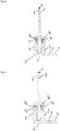
- Figures 1 to 6 shows a holding device 1 for a surface element 2 of a parapet or a railing according to an embodiment of the present invention.
- the holding device 1 according to the invention is shown together with the surface element 2.
- the surface element 2 is a plate, which is preferably a pane of laminated safety glass.
- FIG. 1 a Cartesian coordinate system with the spatial axes X, Y and Z is shown to illustrate the alignment of the holding device 1 in space.
- the two spatial axes X and Y together span a horizontal plane.
- the spatial axis Z is aligned vertically and is perpendicular to the two spatial axes X and Y.
- the holding device 1 has a holding rail 3 which extends along a longitudinal axis L which runs parallel to the spatial axis X.
- the holding rail 3 can be an extruded aluminum profile which has a constant cross section over its entire length.
- the retaining rail is, here, designed as a hollow chamber profile, which could in principle also be made from a solid material.
- the holding rail 3 has a first holding limb 4, a second holding limb 5 and a holding web 6 connecting the two holding limbs 4, 5 to one another.
- the holding rail 3 also has an optional fastening collar 7 which protrudes laterally from the second holding leg 5 in the direction of the spatial axis Y.
- the support surface 8 lies in the horizontal plane which is spanned by the two spatial axes X and Y.
- several fastening bores 9, here three by way of example, are formed, which are used to fasten the retaining rail 3 to a structure (not shown). In the Figure 1 For the sake of clarity, only one of the three fastening bores is provided with the reference number 9.
- the two holding legs 4, 5 protrude from the holding web 6 on both sides of a vertical axis H running parallel to the spatial axis Z and are arranged at the same distance from the vertical axis H. Together with the holding web 6, the holding legs 4, 5 delimit a U-shaped receiving slot 10 for receiving a foot section 11 of the surface element 2.
- the surface element 2 In the inserted state of the surface element 2, which is in the Figures 2 to 6 is shown, the surface element 2 is inserted with the foot portion 11 in the receiving slot 10. It can be seen that the surface element 2 is held exclusively in the receiving slot 10 between the two holding legs 4, 5 and is thus clamped on one side, that is to say in the foot section 11.
- the length of the surface element 2 corresponds, here, at least substantially, that is to say at least 95%, the length of the retaining rail 3.
- sealing strips 12 are arranged, which in the inserted state of the Surface element 2 on this concern and seal the receiving slot 10.
- the sealing strips 12 also cover the clamping elements 13, 14 and the screws 16 arranged in the receiving slot 10.
- Clamping elements 13, 14 are provided for fixing the surface element 2 between the two holding legs 4, 5.
- the clamping elements 13, 14 are arranged adjustably along the vertical axis H and, in addition to fixing the surface element 2, also enable the vertical position of a main plane E spanned by the surface element 2 to be adjusted. In this way, the surface element 2 can be inclined or tilted in the receiving slot 10.
- the vertical position of the main plane E of the surface element 2 inserted between the two clamping elements 13, 14 can thus be compensated for with an angle ⁇ .
- the angle ⁇ can be a maximum of +/- 1 °, for example.
- the clamping elements 13, 14 are designed like a strip and have a main direction of extent that extends parallel to the longitudinal axis L of the holding rail 3.
- Each of the clamping elements 13, 14 has several, here exemplarily seven through bores 15, through each of which a screw 16 extends.
- the screws 16 each define a screw axis A which is aligned parallel to the vertical axis H.
- a first clamping element 13 of the two clamping elements 13, 14 is thus assigned to the first holding leg 4 and a second clamping element 14 of the two clamping elements 13, 14 is assigned to the second holding leg 5.
- the screws 16 extend through the through bores 15 formed in the clamping elements 13, 14.
- Each of the screws 16 is supported with a screw head 17 on a front side of the respective clamping element 13, 14 facing away from the holding web 6.
- the screws 16 each protrude with a threaded section 19 from an underside 20 of the respective clamping element 13, 14 facing the holding web 6.
- the protruding threaded sections 19 of the screws 16 are screwed into the retaining legs 4, 5 at least in sections.
- the two holding legs 4, 5 each have a step 23, 24 on mutually facing inner sides 21, 22, that is to say the inner sides 21, 22 are stepped.
- grooves aligned parallel to the longitudinal axis L are formed for the positive-locking reception of the protruding threaded sections 19 of the screws 16.
- the steps 23, 24 each have a surface 27.
- the surfaces 27 can, as shown here, lie in a common plane which is oriented perpendicular to the vertical axis H.
- the longitudinal slots 26 extend from the surface 27 of the respective step 23, 24 into this.
- the longitudinal slots 26 can also be referred to as screw channels into which the protruding threaded sections 19 of the screws 16 are screwed.
- Resetting elements 28 are arranged between the clamping elements 13, 14 and the steps 23, 24 and act upon the clamping elements 13, 14 with a resetting force F in a direction away from the holding web 6.
- the restoring elements 28 are based on the vertical axis H between the clamping elements 13, 14 and the Steps 23, 24 arranged, the restoring elements 28 being supported on the surfaces 27 of the steps 23, 24 and the undersides 20 of the clamping elements 13, 14.
- the restoring elements 28 are shown, by way of example, as foam strips which extend along the longitudinal axis X of the holding rail 3.
- the restoring elements 28 could also be designed as springs.
- the screws 16 are, here, screwed through the restoring elements 28.
- the two holding legs 4, 5 have support surfaces 29 between the steps 23, 24 and their free ends 18, which are arranged at an angle to the vertical axis H.
- the two support surfaces 29 each span a plane S 4 , S 5 which intersects the vertical axis H at an angle ⁇ 4 , ⁇ 5 .
- the two angles ⁇ 4 , ⁇ 5 are of the same size and have a common point of intersection with the vertical axis H.
- the two angles ⁇ 4 , ⁇ 5 open in a direction away from the holding web 6, so that the two holding legs 4, 5 diverge from one another along the support surfaces 29.
- the lower ends of the support surfaces 29 directly adjoin the steps 23, 24 and their upper ends are spaced apart from the free ends 18 of the holding legs 4, 5.
- the sealing strips 12, which are held on the holding legs 4, 5, are arranged between the support surfaces 29 and the free ends 18.
- the distance between the two retaining legs 4, 5 is thus reduced along the steps 23, 24, as a result of which the receiving slot 10, beginning with the surfaces 27 of the steps 23, 24, is narrowed in a direction towards the retaining web 6.
- the receiving slot 10 tapers further conically.
- the clamping elements 13, 14 each have a mating surface 30, 31 on an outer side facing the respectively assigned holding limb 4, 5, which is in contact with the support surface 29 of the respective holding limb 4, 59.
- the mating surface 30, 31 is aligned parallel to the respectively assigned support surface 29.
- the clamping elements 13, 14 each have a clamping surface 32, 33, between which the foot section 11 of the surface element 2 can be clamped.
- the clamping surfaces 32, 33 are aligned parallel to one another and thus also parallel to the vertical axis H.
- edge protection profiles 34 are still attached, the direct Prevent contact of the clamping elements 13, 14 with the surface element 2.
- the clamping elements 13, 14 can thus be adjusted along the vertical axis H, with the spacing of the clamping surfaces 32, 33 from the vertical axis H changing or increasing or decreasing due to the ramp-like arrangement of the support surfaces 29. In this way, the vertical position of the main plane E spanned by the surface element 2 can be adjusted.
- the spacer 35 is supported by a spacer 35 made of a plastic material on the holding web 6 of the holding rail 3, which allows an adjustment of the vertical position of the main plane E of the surface element 2.
- the spacer 35 extends along the longitudinal axis L and can be slipped onto the lower end of the surface element 2 before the surface element 2 is inserted and inserted into the receiving slot 10 together with the surface element 2.
- the spacer 35 has two opposing profile legs 36, 37 which protrude on both sides of the vertical axis H from an upper side of a profile web 38.
- the profile web 38 connects the two profile legs 36, 37 to one another and can have a cross-section which, here, is configured several times trapezoidal.
- two feet 39 are arranged on an underside of the profile web 38, via which the spacer 35 is supported on the holding web 6.
- the holding rail 3 is aligned when it is attached to the ground, so that the bearing surface 8 lies in the horizontal plane that is spanned by the two spatial axes X and Y.
- the main plane E is aligned parallel to the vertical axis H.
- the surface element 2 stands up vertically and is clamped between the clamping elements 13, 14 arranged on both sides of the surface element 2.
- the surface element 2 still has to be aligned after it has been inserted in order, for example, to compensate for assembly inaccuracies when fastening the retaining rail 3 to the substrate.
- the same may also be necessary when several of the surface elements 2 are arranged one behind the other along the longitudinal axis L, which are to be aligned vertically and parallel to one another.
- the screws 16 are loosened on one of the two clamping elements 13, 14 and tightened further on the other of the two clamping elements 13, 14 in order to build up the clamping pressure on the surface element 2 again.
- the screws 16 on the first clamping element 13 in a maximum position in which they are opposite to that in the Figure 4
- the middle position shown are somewhat loosened or screwed further out of the longitudinal slot 26.
- the screws 16 on the second clamping element 14 are in a minimum position in which they are opposite to that in FIG Figure 4 middle position shown are tightened further or screwed further into the longitudinal slot 26.
- the main plane E of the surface element 2 is tilted towards the second holding leg 5, so that the main plane E encloses the angle ⁇ with the vertical axis H.
- the angle ⁇ corresponds, here, to an angle of approximately 1 °.
Landscapes
- Engineering & Computer Science (AREA)
- General Engineering & Computer Science (AREA)
- Mechanical Engineering (AREA)
- Architecture (AREA)
- Civil Engineering (AREA)
- Structural Engineering (AREA)
- Clamps And Clips (AREA)
Priority Applications (1)
| Application Number | Priority Date | Filing Date | Title |
|---|---|---|---|
| EP19175783.0A EP3742003B1 (fr) | 2019-05-21 | 2019-05-21 | Dispositif de retenue pour un élément de surface |
Applications Claiming Priority (1)
| Application Number | Priority Date | Filing Date | Title |
|---|---|---|---|
| EP19175783.0A EP3742003B1 (fr) | 2019-05-21 | 2019-05-21 | Dispositif de retenue pour un élément de surface |
Publications (2)
| Publication Number | Publication Date |
|---|---|
| EP3742003A1 true EP3742003A1 (fr) | 2020-11-25 |
| EP3742003B1 EP3742003B1 (fr) | 2021-07-07 |
Family
ID=66668701
Family Applications (1)
| Application Number | Title | Priority Date | Filing Date |
|---|---|---|---|
| EP19175783.0A Active EP3742003B1 (fr) | 2019-05-21 | 2019-05-21 | Dispositif de retenue pour un élément de surface |
Country Status (1)
| Country | Link |
|---|---|
| EP (1) | EP3742003B1 (fr) |
Citations (6)
| Publication number | Priority date | Publication date | Assignee | Title |
|---|---|---|---|---|
| US4067548A (en) * | 1976-07-12 | 1978-01-10 | Murphy John J | Railing |
| WO2013121330A2 (fr) * | 2012-02-14 | 2013-08-22 | Metalglas Bonomi S.R.L. | Dispositif de régulation et/ou de verrouillage pour une plaque |
| DE112012006052T5 (de) * | 2012-03-19 | 2014-12-11 | Mitsubishi Electric Corporation | Geländervorrichtung für einen Förderer |
| EP2921607A2 (fr) | 2014-02-26 | 2015-09-23 | SB Ingénierie | Dispositif de fixation d'un panneau dans un rail support |
| WO2015145477A1 (fr) * | 2014-03-25 | 2015-10-01 | Ind.I.A. S.P.A. | Dispositif de verrouillage et de régulation pour panneaux et plaques |
| GB2528147A (en) * | 2015-03-09 | 2016-01-13 | Pure Vista Ltd | System and method for adjusting alignment of a panel |
-
2019
- 2019-05-21 EP EP19175783.0A patent/EP3742003B1/fr active Active
Patent Citations (6)
| Publication number | Priority date | Publication date | Assignee | Title |
|---|---|---|---|---|
| US4067548A (en) * | 1976-07-12 | 1978-01-10 | Murphy John J | Railing |
| WO2013121330A2 (fr) * | 2012-02-14 | 2013-08-22 | Metalglas Bonomi S.R.L. | Dispositif de régulation et/ou de verrouillage pour une plaque |
| DE112012006052T5 (de) * | 2012-03-19 | 2014-12-11 | Mitsubishi Electric Corporation | Geländervorrichtung für einen Förderer |
| EP2921607A2 (fr) | 2014-02-26 | 2015-09-23 | SB Ingénierie | Dispositif de fixation d'un panneau dans un rail support |
| WO2015145477A1 (fr) * | 2014-03-25 | 2015-10-01 | Ind.I.A. S.P.A. | Dispositif de verrouillage et de régulation pour panneaux et plaques |
| GB2528147A (en) * | 2015-03-09 | 2016-01-13 | Pure Vista Ltd | System and method for adjusting alignment of a panel |
Also Published As
| Publication number | Publication date |
|---|---|
| EP3742003B1 (fr) | 2021-07-07 |
Similar Documents
| Publication | Publication Date | Title |
|---|---|---|
| EP0945577B2 (fr) | Utilisation d'une barre profilée pour soutenir des encadrements pour portes ou fenêtres | |
| EP0528213B1 (fr) | Elément de ferrure fixé par serrage dans une gorge profilée ayant au moins une contre-dépouille | |
| DE102013109845A1 (de) | Lager für eine Unterkonstruktion, beispielsweise einer Terrasse | |
| EP2309552A1 (fr) | Réception de serrage et dispositif de fixation pour la fixation de composants en forme de plaques et procédé de fabrication du dispositif de fixation | |
| EP2527762A1 (fr) | Dispositif de fixation | |
| EP0245635B1 (fr) | Dispositif de fixation pour panneaux | |
| EP1892353A1 (fr) | Dispositif pour fixer des planches de plancher sur une structure sous-jacente | |
| DE19831453C2 (de) | Einstellbare Befestigung für Gegenstände, insbesondere Glasplatten auf einer Unterkonstruktion | |
| DE102014119021B4 (de) | Anordnung zum Befestigen eines Pfostens aus Kunststoff an einer Rahmenleiste eines Fensters oder einer Türe mittels eines Pfostenverbinders | |
| EP3612703B1 (fr) | Truelle de montage pour la pose de banquettes de fenêtre et procédé de montage d'une banquette de fenêtre avec cette truelle de montage | |
| EP4067594A1 (fr) | Ferrure de jonction | |
| EP1439269B1 (fr) | Etrier d'ancrage pour profilés pour installations sanitaires et chassis avec un tel étrier | |
| DE4432607A1 (de) | Kraftmeßvorrichtung | |
| DE202007019242U1 (de) | Anordnung zur Lagesicherung einer Befestigungsschraube an einer Profilschiene sowie Bauteil hierfür | |
| DE2722758A1 (de) | Scharnier, insbesondere moebelscharnier | |
| EP3742003B1 (fr) | Dispositif de retenue pour un élément de surface | |
| DE4108455A1 (de) | Montagezwinge zum montieren eines tuerfutters einer tuerzarge | |
| EP1602836B1 (fr) | Nervure raidisseuse pour bois massif | |
| DE2606940A1 (de) | Befestigungsmittel | |
| DE102015118360A1 (de) | Halterung für plattenelemente von brüstungen, geländern und dergleichen | |
| DE102009010428A1 (de) | Vorrichtung zur Verbindung von Profilschienen mit Objekten | |
| DE29516040U1 (de) | Tragstütze sowie Tragvorrichtung mit wenigstens vier im Abstand zueinander angeordneten Tragstützen | |
| DE9212546U1 (de) | Rohrgestell | |
| DE9206203U1 (de) | Gebäude-Glasscheibenkörper als Glaswand oder Glasdach | |
| EP3808916B1 (fr) | Agencement de raccordement mural pour un dispositif de toiture, procédé de fabrication d'un agencement de raccordement mural, utilisation d'un coulisseau et d'un dispositif de toiture |
Legal Events
| Date | Code | Title | Description |
|---|---|---|---|
| PUAI | Public reference made under article 153(3) epc to a published international application that has entered the european phase |
Free format text: ORIGINAL CODE: 0009012 |
|
| STAA | Information on the status of an ep patent application or granted ep patent |
Free format text: STATUS: REQUEST FOR EXAMINATION WAS MADE |
|
| 17P | Request for examination filed |
Effective date: 20200120 |
|
| AK | Designated contracting states |
Kind code of ref document: A1 Designated state(s): AL AT BE BG CH CY CZ DE DK EE ES FI FR GB GR HR HU IE IS IT LI LT LU LV MC MK MT NL NO PL PT RO RS SE SI SK SM TR |
|
| AX | Request for extension of the european patent |
Extension state: BA ME |
|
| GRAP | Despatch of communication of intention to grant a patent |
Free format text: ORIGINAL CODE: EPIDOSNIGR1 |
|
| STAA | Information on the status of an ep patent application or granted ep patent |
Free format text: STATUS: GRANT OF PATENT IS INTENDED |
|
| RIC1 | Information provided on ipc code assigned before grant |
Ipc: F16B 2/06 20060101AFI20210315BHEP Ipc: F16B 2/14 20060101ALI20210315BHEP Ipc: F16B 5/06 20060101ALI20210315BHEP Ipc: F16B 5/12 20060101ALI20210315BHEP Ipc: E04F 11/18 20060101ALI20210315BHEP |
|
| INTG | Intention to grant announced |
Effective date: 20210330 |
|
| GRAS | Grant fee paid |
Free format text: ORIGINAL CODE: EPIDOSNIGR3 |
|
| GRAA | (expected) grant |
Free format text: ORIGINAL CODE: 0009210 |
|
| STAA | Information on the status of an ep patent application or granted ep patent |
Free format text: STATUS: THE PATENT HAS BEEN GRANTED |
|
| AK | Designated contracting states |
Kind code of ref document: B1 Designated state(s): AL AT BE BG CH CY CZ DE DK EE ES FI FR GB GR HR HU IE IS IT LI LT LU LV MC MK MT NL NO PL PT RO RS SE SI SK SM TR |
|
| REG | Reference to a national code |
Ref country code: GB Ref legal event code: FG4D Free format text: NOT ENGLISH |
|
| REG | Reference to a national code |
Ref country code: AT Ref legal event code: REF Ref document number: 1408851 Country of ref document: AT Kind code of ref document: T Effective date: 20210715 |
|
| REG | Reference to a national code |
Ref country code: DE Ref legal event code: R096 Ref document number: 502019001757 Country of ref document: DE |
|
| REG | Reference to a national code |
Ref country code: IE Ref legal event code: FG4D Free format text: LANGUAGE OF EP DOCUMENT: GERMAN |
|
| REG | Reference to a national code |
Ref country code: SE Ref legal event code: TRGR |
|
| REG | Reference to a national code |
Ref country code: NL Ref legal event code: FP |
|
| REG | Reference to a national code |
Ref country code: LT Ref legal event code: MG9D |
|
| PG25 | Lapsed in a contracting state [announced via postgrant information from national office to epo] |
Ref country code: RS Free format text: LAPSE BECAUSE OF FAILURE TO SUBMIT A TRANSLATION OF THE DESCRIPTION OR TO PAY THE FEE WITHIN THE PRESCRIBED TIME-LIMIT Effective date: 20210707 Ref country code: ES Free format text: LAPSE BECAUSE OF FAILURE TO SUBMIT A TRANSLATION OF THE DESCRIPTION OR TO PAY THE FEE WITHIN THE PRESCRIBED TIME-LIMIT Effective date: 20210707 Ref country code: FI Free format text: LAPSE BECAUSE OF FAILURE TO SUBMIT A TRANSLATION OF THE DESCRIPTION OR TO PAY THE FEE WITHIN THE PRESCRIBED TIME-LIMIT Effective date: 20210707 Ref country code: PT Free format text: LAPSE BECAUSE OF FAILURE TO SUBMIT A TRANSLATION OF THE DESCRIPTION OR TO PAY THE FEE WITHIN THE PRESCRIBED TIME-LIMIT Effective date: 20211108 Ref country code: NO Free format text: LAPSE BECAUSE OF FAILURE TO SUBMIT A TRANSLATION OF THE DESCRIPTION OR TO PAY THE FEE WITHIN THE PRESCRIBED TIME-LIMIT Effective date: 20211007 Ref country code: HR Free format text: LAPSE BECAUSE OF FAILURE TO SUBMIT A TRANSLATION OF THE DESCRIPTION OR TO PAY THE FEE WITHIN THE PRESCRIBED TIME-LIMIT Effective date: 20210707 Ref country code: BG Free format text: LAPSE BECAUSE OF FAILURE TO SUBMIT A TRANSLATION OF THE DESCRIPTION OR TO PAY THE FEE WITHIN THE PRESCRIBED TIME-LIMIT Effective date: 20211007 Ref country code: LT Free format text: LAPSE BECAUSE OF FAILURE TO SUBMIT A TRANSLATION OF THE DESCRIPTION OR TO PAY THE FEE WITHIN THE PRESCRIBED TIME-LIMIT Effective date: 20210707 |
|
| PG25 | Lapsed in a contracting state [announced via postgrant information from national office to epo] |
Ref country code: PL Free format text: LAPSE BECAUSE OF FAILURE TO SUBMIT A TRANSLATION OF THE DESCRIPTION OR TO PAY THE FEE WITHIN THE PRESCRIBED TIME-LIMIT Effective date: 20210707 Ref country code: LV Free format text: LAPSE BECAUSE OF FAILURE TO SUBMIT A TRANSLATION OF THE DESCRIPTION OR TO PAY THE FEE WITHIN THE PRESCRIBED TIME-LIMIT Effective date: 20210707 Ref country code: GR Free format text: LAPSE BECAUSE OF FAILURE TO SUBMIT A TRANSLATION OF THE DESCRIPTION OR TO PAY THE FEE WITHIN THE PRESCRIBED TIME-LIMIT Effective date: 20211008 |
|
| REG | Reference to a national code |
Ref country code: DE Ref legal event code: R097 Ref document number: 502019001757 Country of ref document: DE |
|
| PG25 | Lapsed in a contracting state [announced via postgrant information from national office to epo] |
Ref country code: DK Free format text: LAPSE BECAUSE OF FAILURE TO SUBMIT A TRANSLATION OF THE DESCRIPTION OR TO PAY THE FEE WITHIN THE PRESCRIBED TIME-LIMIT Effective date: 20210707 |
|
| PLBE | No opposition filed within time limit |
Free format text: ORIGINAL CODE: 0009261 |
|
| STAA | Information on the status of an ep patent application or granted ep patent |
Free format text: STATUS: NO OPPOSITION FILED WITHIN TIME LIMIT |
|
| PG25 | Lapsed in a contracting state [announced via postgrant information from national office to epo] |
Ref country code: SM Free format text: LAPSE BECAUSE OF FAILURE TO SUBMIT A TRANSLATION OF THE DESCRIPTION OR TO PAY THE FEE WITHIN THE PRESCRIBED TIME-LIMIT Effective date: 20210707 Ref country code: SK Free format text: LAPSE BECAUSE OF FAILURE TO SUBMIT A TRANSLATION OF THE DESCRIPTION OR TO PAY THE FEE WITHIN THE PRESCRIBED TIME-LIMIT Effective date: 20210707 Ref country code: RO Free format text: LAPSE BECAUSE OF FAILURE TO SUBMIT A TRANSLATION OF THE DESCRIPTION OR TO PAY THE FEE WITHIN THE PRESCRIBED TIME-LIMIT Effective date: 20210707 Ref country code: EE Free format text: LAPSE BECAUSE OF FAILURE TO SUBMIT A TRANSLATION OF THE DESCRIPTION OR TO PAY THE FEE WITHIN THE PRESCRIBED TIME-LIMIT Effective date: 20210707 Ref country code: CZ Free format text: LAPSE BECAUSE OF FAILURE TO SUBMIT A TRANSLATION OF THE DESCRIPTION OR TO PAY THE FEE WITHIN THE PRESCRIBED TIME-LIMIT Effective date: 20210707 Ref country code: AL Free format text: LAPSE BECAUSE OF FAILURE TO SUBMIT A TRANSLATION OF THE DESCRIPTION OR TO PAY THE FEE WITHIN THE PRESCRIBED TIME-LIMIT Effective date: 20210707 |
|
| 26N | No opposition filed |
Effective date: 20220408 |
|
| PG25 | Lapsed in a contracting state [announced via postgrant information from national office to epo] |
Ref country code: MC Free format text: LAPSE BECAUSE OF FAILURE TO SUBMIT A TRANSLATION OF THE DESCRIPTION OR TO PAY THE FEE WITHIN THE PRESCRIBED TIME-LIMIT Effective date: 20210707 Ref country code: LU Free format text: LAPSE BECAUSE OF NON-PAYMENT OF DUE FEES Effective date: 20220521 |
|
| PG25 | Lapsed in a contracting state [announced via postgrant information from national office to epo] |
Ref country code: IE Free format text: LAPSE BECAUSE OF NON-PAYMENT OF DUE FEES Effective date: 20220521 |
|
| GBPC | Gb: european patent ceased through non-payment of renewal fee |
Effective date: 20230521 |
|
| PG25 | Lapsed in a contracting state [announced via postgrant information from national office to epo] |
Ref country code: MK Free format text: LAPSE BECAUSE OF FAILURE TO SUBMIT A TRANSLATION OF THE DESCRIPTION OR TO PAY THE FEE WITHIN THE PRESCRIBED TIME-LIMIT Effective date: 20210707 Ref country code: CY Free format text: LAPSE BECAUSE OF FAILURE TO SUBMIT A TRANSLATION OF THE DESCRIPTION OR TO PAY THE FEE WITHIN THE PRESCRIBED TIME-LIMIT Effective date: 20210707 Ref country code: GB Free format text: LAPSE BECAUSE OF NON-PAYMENT OF DUE FEES Effective date: 20230521 |
|
| PG25 | Lapsed in a contracting state [announced via postgrant information from national office to epo] |
Ref country code: HU Free format text: LAPSE BECAUSE OF FAILURE TO SUBMIT A TRANSLATION OF THE DESCRIPTION OR TO PAY THE FEE WITHIN THE PRESCRIBED TIME-LIMIT; INVALID AB INITIO Effective date: 20190521 |
|
| PG25 | Lapsed in a contracting state [announced via postgrant information from national office to epo] |
Ref country code: TR Free format text: LAPSE BECAUSE OF FAILURE TO SUBMIT A TRANSLATION OF THE DESCRIPTION OR TO PAY THE FEE WITHIN THE PRESCRIBED TIME-LIMIT Effective date: 20210707 |
|
| PG25 | Lapsed in a contracting state [announced via postgrant information from national office to epo] |
Ref country code: MT Free format text: LAPSE BECAUSE OF FAILURE TO SUBMIT A TRANSLATION OF THE DESCRIPTION OR TO PAY THE FEE WITHIN THE PRESCRIBED TIME-LIMIT Effective date: 20210707 |
|
| PGFP | Annual fee paid to national office [announced via postgrant information from national office to epo] |
Ref country code: NL Payment date: 20250522 Year of fee payment: 7 |
|
| PGFP | Annual fee paid to national office [announced via postgrant information from national office to epo] |
Ref country code: DE Payment date: 20250519 Year of fee payment: 7 |
|
| PGFP | Annual fee paid to national office [announced via postgrant information from national office to epo] |
Ref country code: BE Payment date: 20250520 Year of fee payment: 7 Ref country code: IT Payment date: 20250530 Year of fee payment: 7 |
|
| PGFP | Annual fee paid to national office [announced via postgrant information from national office to epo] |
Ref country code: FR Payment date: 20250521 Year of fee payment: 7 |
|
| PGFP | Annual fee paid to national office [announced via postgrant information from national office to epo] |
Ref country code: CH Payment date: 20250601 Year of fee payment: 7 |
|
| PGFP | Annual fee paid to national office [announced via postgrant information from national office to epo] |
Ref country code: AT Payment date: 20250519 Year of fee payment: 7 |
|
| PGFP | Annual fee paid to national office [announced via postgrant information from national office to epo] |
Ref country code: SE Payment date: 20250522 Year of fee payment: 7 |