EP3744464A1 - Système de changement rapide pour buses traînées de gaz de protection - Google Patents
Système de changement rapide pour buses traînées de gaz de protection Download PDFInfo
- Publication number
- EP3744464A1 EP3744464A1 EP19020349.7A EP19020349A EP3744464A1 EP 3744464 A1 EP3744464 A1 EP 3744464A1 EP 19020349 A EP19020349 A EP 19020349A EP 3744464 A1 EP3744464 A1 EP 3744464A1
- Authority
- EP
- European Patent Office
- Prior art keywords
- recess
- carrier element
- adapter ring
- gas nozzle
- section
- Prior art date
- Legal status (The legal status is an assumption and is not a legal conclusion. Google has not performed a legal analysis and makes no representation as to the accuracy of the status listed.)
- Withdrawn
Links
- 239000011261 inert gas Substances 0.000 title description 2
- 239000000725 suspension Substances 0.000 claims abstract description 17
- 238000003466 welding Methods 0.000 claims description 13
- 239000000463 material Substances 0.000 claims description 8
- 238000003801 milling Methods 0.000 claims description 3
- 239000007789 gas Substances 0.000 description 44
- 238000000034 method Methods 0.000 description 5
- 239000002184 metal Substances 0.000 description 3
- 230000002093 peripheral effect Effects 0.000 description 3
- 230000000694 effects Effects 0.000 description 2
- 230000003647 oxidation Effects 0.000 description 2
- 238000007254 oxidation reaction Methods 0.000 description 2
- 230000001681 protective effect Effects 0.000 description 2
- 241001156002 Anthonomus pomorum Species 0.000 description 1
- 229910000831 Steel Inorganic materials 0.000 description 1
- 238000005452 bending Methods 0.000 description 1
- 238000004140 cleaning Methods 0.000 description 1
- 239000011248 coating agent Substances 0.000 description 1
- 238000000576 coating method Methods 0.000 description 1
- 229920001971 elastomer Polymers 0.000 description 1
- 239000000806 elastomer Substances 0.000 description 1
- 238000005516 engineering process Methods 0.000 description 1
- 238000010438 heat treatment Methods 0.000 description 1
- 238000003780 insertion Methods 0.000 description 1
- 230000037431 insertion Effects 0.000 description 1
- 238000003754 machining Methods 0.000 description 1
- 238000004519 manufacturing process Methods 0.000 description 1
- 230000013011 mating Effects 0.000 description 1
- 239000004033 plastic Substances 0.000 description 1
- 229920003023 plastic Polymers 0.000 description 1
- 239000010959 steel Substances 0.000 description 1
Images

Classifications
-
- B—PERFORMING OPERATIONS; TRANSPORTING
- B23—MACHINE TOOLS; METAL-WORKING NOT OTHERWISE PROVIDED FOR
- B23K—SOLDERING OR UNSOLDERING; WELDING; CLADDING OR PLATING BY SOLDERING OR WELDING; CUTTING BY APPLYING HEAT LOCALLY, e.g. FLAME CUTTING; WORKING BY LASER BEAM
- B23K37/00—Auxiliary devices or processes, not specially adapted for a procedure covered by only one of the other main groups of this subclass
-
- B—PERFORMING OPERATIONS; TRANSPORTING
- B23—MACHINE TOOLS; METAL-WORKING NOT OTHERWISE PROVIDED FOR
- B23K—SOLDERING OR UNSOLDERING; WELDING; CLADDING OR PLATING BY SOLDERING OR WELDING; CUTTING BY APPLYING HEAT LOCALLY, e.g. FLAME CUTTING; WORKING BY LASER BEAM
- B23K26/00—Working by laser beam, e.g. welding, cutting or boring
- B23K26/14—Working by laser beam, e.g. welding, cutting or boring using a fluid stream, e.g. a jet of gas, in conjunction with the laser beam; Nozzles therefor
-
- B—PERFORMING OPERATIONS; TRANSPORTING
- B23—MACHINE TOOLS; METAL-WORKING NOT OTHERWISE PROVIDED FOR
- B23K—SOLDERING OR UNSOLDERING; WELDING; CLADDING OR PLATING BY SOLDERING OR WELDING; CUTTING BY APPLYING HEAT LOCALLY, e.g. FLAME CUTTING; WORKING BY LASER BEAM
- B23K9/00—Arc welding or cutting
- B23K9/16—Arc welding or cutting making use of shielding gas
-
- B—PERFORMING OPERATIONS; TRANSPORTING
- B23—MACHINE TOOLS; METAL-WORKING NOT OTHERWISE PROVIDED FOR
- B23K—SOLDERING OR UNSOLDERING; WELDING; CLADDING OR PLATING BY SOLDERING OR WELDING; CUTTING BY APPLYING HEAT LOCALLY, e.g. FLAME CUTTING; WORKING BY LASER BEAM
- B23K9/00—Arc welding or cutting
- B23K9/24—Features related to electrodes
- B23K9/28—Supporting devices for electrodes
- B23K9/29—Supporting devices adapted for making use of shielding means
- B23K9/291—Supporting devices adapted for making use of shielding means the shielding means being a gas
-
- B—PERFORMING OPERATIONS; TRANSPORTING
- B23—MACHINE TOOLS; METAL-WORKING NOT OTHERWISE PROVIDED FOR
- B23K—SOLDERING OR UNSOLDERING; WELDING; CLADDING OR PLATING BY SOLDERING OR WELDING; CUTTING BY APPLYING HEAT LOCALLY, e.g. FLAME CUTTING; WORKING BY LASER BEAM
- B23K26/00—Working by laser beam, e.g. welding, cutting or boring
- B23K26/14—Working by laser beam, e.g. welding, cutting or boring using a fluid stream, e.g. a jet of gas, in conjunction with the laser beam; Nozzles therefor
- B23K26/1462—Nozzles; Features related to nozzles
- B23K26/1482—Detachable nozzles, e.g. exchangeable or provided with breakaway lines
-
- B—PERFORMING OPERATIONS; TRANSPORTING
- B23—MACHINE TOOLS; METAL-WORKING NOT OTHERWISE PROVIDED FOR
- B23K—SOLDERING OR UNSOLDERING; WELDING; CLADDING OR PLATING BY SOLDERING OR WELDING; CUTTING BY APPLYING HEAT LOCALLY, e.g. FLAME CUTTING; WORKING BY LASER BEAM
- B23K9/00—Arc welding or cutting
- B23K9/32—Accessories
- B23K9/325—Devices for supplying or evacuating shielding gas
Definitions
- the invention relates to a device for replaceable fastening of a gas nozzle for a welding process.
- gases are introduced into the work area on the workpiece for various purposes.
- these are protective gases, that is to say for example inert gases, which form a gas layer around the processing area and prevent oxidation of the materials during or after a welding process or during heat treatment.
- gases can be used specifically to influence machining parameters.
- the shielding gas is usually emitted via nozzles that are integrated with the burner.
- it may also be necessary or useful to apply gas to the further or already processed area in addition to the protective gas in the direct processing area, for example until the oxidation temperature is undershot.
- This secondary gas protection is often achieved by so-called drag nozzles, which are also attached to the burner or to trailing covers such as e.g. attached to a towing shoe.
- the drag nozzle is usually attached to the torch or the drag shoe using hose clips and similar clamping elements.
- a clamp is fixed on the burner tube, into which a gas nozzle can be inserted and then firmly clamped by screwing the clamp.
- Another possibility is to use nozzles that are provided with a suitable thread and firmly screwed to the burner element or a cover. Drag nozzles can also already be permanently integrated into a burner.
- the invention is therefore based on the object of achieving a simpler arrangement of a gas nozzle.
- a device for replaceable fastening of a gas nozzle comprising a long carrier element which has a nozzle section for fastening a gas nozzle and is provided with a curved hanging section, and a holding component which is provided with at least one Recess is provided, which is shaped so that the suspension portion of the carrier element can be introduced into the recess, so that a form-fitting engagement between the carrier element and the holding component is created.
- a gas nozzle can be attached to a corresponding holding component by simply hanging and unhooking it, and it can be quickly replaced without the use of tools.
- Such a device is particularly suitable for drag gas nozzles that are additionally attached, but can also be used for other gas nozzles.
- the holding component can comprise an adapter ring which can be fastened to a tubular component, such as directly to a burner or another element.
- a recess can then be arranged, for example, in an axial end surface and / or in the outer circumferential surface of the adapter ring.
- the attachment can thus be flexibly adapted to the respective space conditions.
- the adapter ring can also be provided with a plurality of recesses spaced apart from one another in the axial direction and / or along the circumference of the adapter ring, so that the nozzle position can be quickly changed at defined intervals without repositioning the adapter ring.
- a recess can run at an angle to the central axis of the adapter ring, the angle being less than 90 °.
- All of the recesses can be made as a blind hole, elongated hole or as a through hole or in the form of a milling. Such a recess can be implemented, for example, by milling along the circumferential direction of the adapter ring.
- the shape of the at least one recess corresponds essentially to the shape of the suspension section, the dimensions being relatively accurate or with Game can be provided as long as the hold of the components is sufficiently strong to one another.
- the carrier element can be made from a strip-shaped piece of material, for example from a sufficiently thick sheet metal strip, which can be formed into a carrier element in a simple manner by bending or other forming processes.
- the holding component can be designed in one piece with a welding torch or a holder for a welding torch, so that no adapter is necessary.
- a device according to the invention for attaching a gas nozzle offers various advantages. Since the gas nozzle can be fixed to the rigid carrier element and the position and distance from the adapter ring can thus remain constant, the optimal distance between the gas nozzle and the processing area can be reliably maintained. By moving the adapter ring on the burner, this distance can also be changed as required and set to a new value. The nozzle can be attached and detached without tools and makes it easier to change or clean the nozzle, so that downtimes are significantly reduced. A change of the gas nozzle to suit the respective welding task is easily possible thanks to the quick assembly. In addition, such a system can be used with any burner as long as the corresponding adapter element can be attached or a suitable recess is available for the carrier element.
- adapter rings in different diameters can be provided with a single nozzle carrier element and can thus be adapted to several types of torch.
- Another advantage is that even if the gas nozzle collides with the component surface, e.g. by abutment, the fastening of the gas nozzle thus carried out gives way and e.g. is partially pushed upwards out of the recess so that the burner and the gas nozzle are not damaged.
- a quick-change holder which comprises a carrier element for a gas nozzle and a corresponding recess on a holding component such as on a burner, on an adapter element or on another suitable element.
- the recess is designed in such a way that a curved suspension section of the carrier element can be introduced into the recess and can hold the carrier element there in a predetermined position by means of a form fit.
- the dimensions of the recess therefore correspond at least to the suspension section to be introduced therein, but can also be designed to be larger by a certain amount, as long as a secure hold of the carrier element in the recess is ensured.
- an adapter element it should be dimensioned with regard to its wall thickness or its circumference such that the recess can be accommodated therein.
- the recess can be opened essentially in a direction which, when the adapter element is attached, points away from the burner nozzle during operation.
- the quick-change holder can preferably be designed as a two-part device, in which a separate adapter element with the corresponding recess is provided as the holding component.
- the adapter element in turn has fastening areas with which it can be fastened, for example, to a welding torch 40 or another tubular component such as a holder.
- the adapter element can be a one-part or multi-part adapter ring which is designed so that it can be attached, for example, around a burner tube or slipped onto it and clamped there by screwing.
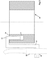
- a recess 22 can then be provided at at least one point in the adapter ring 20, which recess is shaped in such a way that it can receive a hanging section 12 of a carrier element 10 and can bring the carrier element into positive engagement with the adapter ring 20.
- the end region of the carrier element 10 and thus also the recess 22 can be designed with a uniform rectangular or flat cross section, or alternatively with a cross section that follows the curved circumference of the adapter ring, for example.
- the recess can be provided, for example, in an axial end face 24 of the adapter ring 20 and run essentially perpendicular to the ring axis, so that the suspended carrier element effects the form fit due to its weight.
- the recess 22 can also run at an angle ⁇ to the axis of the adapter ring 20, as will be described in more detail in further embodiments, wherein the angle should be smaller than 90 ° and preferably smaller than approx. 45 ° or smaller than 30 °, to ensure a secure form fit when hanging.
- the suspension section 12 of the carrier element 10 can then also run at an angle.
- the carrier element 10 shown is designed in the form of a simple strip-shaped angle.
- a carrier element 10 can be produced very easily by suitable forming processes from a strip-shaped piece of material, for example a sufficiently stable sheet metal, and therefore offers a particularly cost-effective production process.
- differently shaped carrier elements can also be used which follow the same fastening principle in a corresponding recess 22.
- FIG. 2 shows a radial cross section through an adapter element in the form of an adapter ring 20, which as in FIG Figure 1 on a burner 40 or a bracket, etc. can be attached.
- the recess 22 for the carrier element is made here in the form of a vertical blind hole in the upper annular surface 24, that is to say in the surface which faces away from the burner nozzle during operation.
- the suitably shaped carrier element is hung with a curved end region 12 in the recess 22, so that a secure form fit is produced by the weight of the carrier element 10 and the nozzle 30 attached to it.
- the connection can be released again by simply lifting the carrier element 10 in the opposite direction and the gas nozzle 30 attached to the carrier element 10 can thus be changed quickly.
- the suspension section 12 is shown here as an angularly curved area with two essentially right-angled bends, but it can also be curved or rounded, for example with a U-shaped profile.
- the carrier element 10 comprises a nozzle section 16 for fastening a gas nozzle 30, in which, for example, integrated fastening means or receptacles for separate fastening means can be provided in order to fasten a gas nozzle to the carrier element.
- These can be openings for screws, clamping elements such as hose clamps, internal or external threads to accommodate a correspondingly designed mating thread or other means.
- a gas nozzle 30 can then be fixed detachably or permanently rigidly on the carrier element 10.
- the fastening means can also be designed such that different nozzle elements, for example with different diameters, or different fastening systems such as screws and clamp brackets can be connected to them.
- the nozzle section 16 of the carrier element 10 is no longer shown, but should of course be transferred to these examples.
- the shape and design of the nozzle section can also be designed differently than shown here, as long as the gas nozzle can be attached.
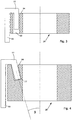
- an adapter ring 20 is shown in which as in FIG Figure 2 a recess 22 running parallel to the ring axis is made in the end face 24 of the ring.
- the recess is designed as a through hole here.
- the corresponding hook-in section 12 of the carrier element can then be made shorter than the hole or also longer, so that the hooked-in carrier element 12 can also emerge again at the other annular surface, depending on the dimensions.
- the extended length of the suspension section 12 can ensure a particularly stable fit.
- Figure 4 shows an embodiment in which a recess 22 is also arranged in the axial end face 24, but is tilted outwards by an angle ⁇ with respect to the central axis of the ring 20.
- a recess 22 is also arranged in the axial end face 24, but is tilted outwards by an angle ⁇ with respect to the central axis of the ring 20.
- Such an embodiment can simplify the insertion of the carrier element 12 into the recess and also offers a slight hold against the carrier element 10 being pushed out upwards, for example if the carrier element or the gas nozzle accidentally hit.
- the angle and the dimensions of the suspension section are preferably matched to one another in order to ensure a secure hold.
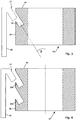
- FIG. 5 an embodiment is shown in which a recess 22 is arranged in the outer peripheral surface 26 of the adapter ring 20.
- the recess is tilted at an angle ⁇ to the axis.
- a recess in the circumferential surface 26 offers advantages, for example, when there is only little space upwards along the ring axis (or the burner axis).
- such a recess can also easily be made in any other components with sufficient wall thickness, for example directly in a holder or casing of a welding torch.
- an adapter ring 20 is shown, in which two as in Figure 5 designed recesses 22a, 22b are attached one above the other. It goes without saying that the recesses do not have to be arranged directly one above the other, but can also be arranged offset over the circumference of the ring 20. On In this way, several holding options at different distances from the workpiece can be provided for the gas nozzle 30, which can be set quickly without moving the adapter element 20 and thereby enable precisely defined dimensions. Significantly more than two recesses could be made along the axis of the burner and the nozzle position could be varied flexibly by hanging and unhooking the carrier element without having to move the adapter ring 20.
- a plurality of recesses 22 can also be arranged around the circumference of the adapter ring 20 in all the embodiments shown. In this way, the angle of the gas nozzle 30 to the processing area can be quickly adjusted, or the gas nozzle can be relocated for a short time in the case of special space conditions, particularly during manual welding.
- recesses in the circumferential surface 26 and recesses in the end surface 24 can of course also be combined with one another as desired.
- the recess for receiving the suspension section can also comprise several separate areas.
- the end area of the carrier element could be designed in such a way that two or more separate hook arms engage in corresponding, matching recesses in the adapter ring.
- the recesses for these arms could be designed contiguously or individually.
- a wider or stepped adapter ring could also be used, which makes it possible to change the distance between the gas nozzle and the burner in a simple manner, even in the radial direction.
- several recesses spaced apart in the radial direction could be made on a wider adapter ring so that a suitably shaped suspension section with a sufficiently wide support surface can be suspended at different radii or distances from the burner axis.
- the suspension section should be designed for all embodiments so that it can be suspended in the adapter ring in any intended position without risking the correct suspension and the tight fit of the gas nozzle.
- the upper area which adjoins the hanging section 12 and in embodiments such as in FIG Figures 2 and 3 shown comes to rest on the edge of the adapter ring, have a sufficient width. The width of this area can optionally be used to define the distance between the attached gas nozzle and the burner.
- a gas nozzle 30 in one piece with a corresponding carrier element, that is to say, for example, with a corresponding hanging section which is provided for hanging in the recesses as described above.
- a suitable material for the carrier element 10 and the holding component 20 is, for example, a metal, such as any steel, but plastics or other suitable materials are also conceivable. It goes without saying that heat resistance and other features such as sufficient rigidity of the material must be taken into account for the selection.
- a compressible elastomer coating of the recess 22 and / or the suspension section 12 could also help to fix the carrier element 10 more firmly in the recess 22 by means of a clamping force.
- a corresponding recess can also be provided directly in the cover instead of an adapter element.
- a burner could already be equipped in one piece with a holding component that has at least one corresponding recess.
Landscapes
- Engineering & Computer Science (AREA)
- Physics & Mathematics (AREA)
- Optics & Photonics (AREA)
- Mechanical Engineering (AREA)
- Plasma & Fusion (AREA)
- Gas Burners (AREA)
- Arc Welding In General (AREA)
- Clamps And Clips (AREA)
- Connection Of Plates (AREA)
Priority Applications (7)
| Application Number | Priority Date | Filing Date | Title |
|---|---|---|---|
| EP19020349.7A EP3744464A1 (fr) | 2019-05-28 | 2019-05-28 | Système de changement rapide pour buses traînées de gaz de protection |
| PCT/EP2020/025232 WO2020239254A1 (fr) | 2019-05-28 | 2020-05-19 | Système de changement rapide destiné à des buses à remorquer à gaz protecteur |
| BR112021022716A BR112021022716A2 (pt) | 2019-05-28 | 2020-05-19 | Dispositivo para fixação intercambiável de um bocal de gás, e, maçarico |
| CN202080035618.5A CN113840683A (zh) | 2019-05-28 | 2020-05-19 | 用于保护气体拖曳式喷嘴的快速更换系统 |
| MX2021014060A MX2021014060A (es) | 2019-05-28 | 2020-05-19 | Sistema de cambio rapido para boquillas de arrastre de gas de proteccion. |
| EP20728671.7A EP3976305A1 (fr) | 2019-05-28 | 2020-05-19 | Système de changement rapide destiné à des buses à remorquer à gaz protecteur |
| US17/595,484 US20220226941A1 (en) | 2019-05-28 | 2020-05-19 | Quick-change system for shielding-gas drag nozzles |
Applications Claiming Priority (1)
| Application Number | Priority Date | Filing Date | Title |
|---|---|---|---|
| EP19020349.7A EP3744464A1 (fr) | 2019-05-28 | 2019-05-28 | Système de changement rapide pour buses traînées de gaz de protection |
Publications (1)
| Publication Number | Publication Date |
|---|---|
| EP3744464A1 true EP3744464A1 (fr) | 2020-12-02 |
Family
ID=66676158
Family Applications (2)
| Application Number | Title | Priority Date | Filing Date |
|---|---|---|---|
| EP19020349.7A Withdrawn EP3744464A1 (fr) | 2019-05-28 | 2019-05-28 | Système de changement rapide pour buses traînées de gaz de protection |
| EP20728671.7A Withdrawn EP3976305A1 (fr) | 2019-05-28 | 2020-05-19 | Système de changement rapide destiné à des buses à remorquer à gaz protecteur |
Family Applications After (1)
| Application Number | Title | Priority Date | Filing Date |
|---|---|---|---|
| EP20728671.7A Withdrawn EP3976305A1 (fr) | 2019-05-28 | 2020-05-19 | Système de changement rapide destiné à des buses à remorquer à gaz protecteur |
Country Status (6)
| Country | Link |
|---|---|
| US (1) | US20220226941A1 (fr) |
| EP (2) | EP3744464A1 (fr) |
| CN (1) | CN113840683A (fr) |
| BR (1) | BR112021022716A2 (fr) |
| MX (1) | MX2021014060A (fr) |
| WO (1) | WO2020239254A1 (fr) |
Citations (2)
| Publication number | Priority date | Publication date | Assignee | Title |
|---|---|---|---|---|
| US20130068745A1 (en) * | 2011-09-15 | 2013-03-21 | Lincoln Global | Gas shielding device for a welding system |
| US20140231605A1 (en) * | 2013-02-19 | 2014-08-21 | Gary L. Sharpe | Multi-functional clamp |
Family Cites Families (14)
| Publication number | Priority date | Publication date | Assignee | Title |
|---|---|---|---|---|
| JPH0666874U (ja) * | 1993-02-24 | 1994-09-20 | 豊田鉄工株式会社 | 溶接トーチのサイドシールドガスノズル |
| WO2007005728A2 (fr) * | 2005-07-01 | 2007-01-11 | L & P Property Management Company | Systeme de rayonnage reglable |
| JP5615586B2 (ja) * | 2010-04-16 | 2014-10-29 | 株式会社ダイヘン | アーク溶接用トーチ |
| US9498107B2 (en) * | 2010-08-06 | 2016-11-22 | Carefusion 2200, Inc. | Clamping system |
| CN201871857U (zh) * | 2010-11-29 | 2011-06-22 | 北京时代科技股份有限公司 | 保护拖罩 |
| DE102011106684A1 (de) * | 2011-07-06 | 2013-01-10 | Daimler Ag | Abluftabsaugung für eine Fugevorrichtung zum Schweißen oder Löten |
| FR3001088B1 (fr) * | 2013-01-11 | 2015-03-06 | Airbus Operations Sas | Dispositif de montage de systemes d'alimentation pour aeronef |
| JP5899127B2 (ja) * | 2013-01-15 | 2016-04-06 | 白光株式会社 | 自動半田付けユニット及び調整治具 |
| CN104493360A (zh) * | 2014-12-04 | 2015-04-08 | 北京航星机器制造有限公司 | 激光柔性焊接焊缝气体保护装置 |
| CN104889628B (zh) * | 2015-06-17 | 2017-01-04 | 柯马(上海)工程有限公司 | 一种随行定位工装快速切换的自动化机构 |
| CN105171238A (zh) * | 2015-09-21 | 2015-12-23 | 洛阳鹏起实业有限公司 | 激光焊接气体保护装置 |
| CN205057296U (zh) * | 2015-10-27 | 2016-03-02 | 中国人民解放军装甲兵工程学院 | 一种厚板窄间隙激光焊接用气体保护装置 |
| CN109414780B (zh) * | 2016-06-24 | 2021-10-08 | 通快机床两合公司 | 具有耦合装置的用于在使用热加工射束的情况下加工工件的加工单元 |
| CN208246057U (zh) * | 2018-04-18 | 2018-12-18 | 西南交通大学 | 一种用于异种金属熔钎焊的气体保护及成型控制装置 |
-
2019
- 2019-05-28 EP EP19020349.7A patent/EP3744464A1/fr not_active Withdrawn
-
2020
- 2020-05-19 MX MX2021014060A patent/MX2021014060A/es unknown
- 2020-05-19 BR BR112021022716A patent/BR112021022716A2/pt not_active Application Discontinuation
- 2020-05-19 US US17/595,484 patent/US20220226941A1/en not_active Abandoned
- 2020-05-19 EP EP20728671.7A patent/EP3976305A1/fr not_active Withdrawn
- 2020-05-19 WO PCT/EP2020/025232 patent/WO2020239254A1/fr not_active Ceased
- 2020-05-19 CN CN202080035618.5A patent/CN113840683A/zh active Pending
Patent Citations (2)
| Publication number | Priority date | Publication date | Assignee | Title |
|---|---|---|---|---|
| US20130068745A1 (en) * | 2011-09-15 | 2013-03-21 | Lincoln Global | Gas shielding device for a welding system |
| US20140231605A1 (en) * | 2013-02-19 | 2014-08-21 | Gary L. Sharpe | Multi-functional clamp |
Also Published As
| Publication number | Publication date |
|---|---|
| US20220226941A1 (en) | 2022-07-21 |
| WO2020239254A1 (fr) | 2020-12-03 |
| EP3976305A1 (fr) | 2022-04-06 |
| BR112021022716A2 (pt) | 2021-12-28 |
| CN113840683A (zh) | 2021-12-24 |
| MX2021014060A (es) | 2021-12-10 |
Similar Documents
| Publication | Publication Date | Title |
|---|---|---|
| EP2085173B1 (fr) | Procédé de commande de processus d'une installation de soudure de robot pour verification périodique de la maintenance en vu de changer la buse de gaz | |
| EP2819799B1 (fr) | Mandrin de frettage avec refroidissement de l'outil | |
| EP3784445B1 (fr) | Dispositif pour une machine-outil portative et machine-outil portative | |
| CH656080A5 (de) | Drehwerkzeug fuer die endenbearbeitung von wellen, zapfen, rohren. | |
| EP3362212A1 (fr) | Outil d'usinage par enlèvement de copeaux | |
| CH624865A5 (fr) | ||
| EP3239586A1 (fr) | Dispositif de retenue destiné à fixer un isolant et outil associé | |
| EP3582917A2 (fr) | Scie cloche | |
| EP0718080A1 (fr) | Lame de scie | |
| DE69923362T2 (de) | Werkzeug zur spanabhebenden Bearbeitung | |
| EP2070655A2 (fr) | Dispositif de positionnement destiné à la fixation d'une pièce usinée | |
| EP3320220A1 (fr) | Élément de fixation pour un rail de montage | |
| EP4170096B1 (fr) | Outil de laminage pour un rouleau de traitement du sol | |
| EP3500786A1 (fr) | Griffe de fixation | |
| EP3744464A1 (fr) | Système de changement rapide pour buses traînées de gaz de protection | |
| DE102019111843B4 (de) | Zerspanungswerkzeug | |
| DE102011105743A1 (de) | Biegegesenk | |
| DE202009010943U1 (de) | Werkzeug zur spanabhebenden Bearbeitung von Werkstücken | |
| WO2007048467A1 (fr) | Porte-outil | |
| DE60301803T2 (de) | Vorrichtung zur Realisierung des Zusammenbaus eines Ventilschafts und eines Federtellers | |
| EP4163526B1 (fr) | Élément de fixation de type manchette, ainsi qu'élément de centrage | |
| EP3043938B1 (fr) | Outil de coupe | |
| DE102013214154A1 (de) | Kopfstück, Anschlaghalter und Verfahren zum Stabilisieren einer Bohrmaschine | |
| DE102016118121A1 (de) | Werkzeugmaschine und Verfahren zur Bearbeitung eines Werkstücks mit einer Werkzeugmaschine | |
| DE202025103288U1 (de) | Bedienteil zur Betätigung einer Spannmutter |
Legal Events
| Date | Code | Title | Description |
|---|---|---|---|
| PUAI | Public reference made under article 153(3) epc to a published international application that has entered the european phase |
Free format text: ORIGINAL CODE: 0009012 |
|
| STAA | Information on the status of an ep patent application or granted ep patent |
Free format text: STATUS: THE APPLICATION HAS BEEN PUBLISHED |
|
| AK | Designated contracting states |
Kind code of ref document: A1 Designated state(s): AL AT BE BG CH CY CZ DE DK EE ES FI FR GB GR HR HU IE IS IT LI LT LU LV MC MK MT NL NO PL PT RO RS SE SI SK SM TR |
|
| AX | Request for extension of the european patent |
Extension state: BA ME |
|
| STAA | Information on the status of an ep patent application or granted ep patent |
Free format text: STATUS: THE APPLICATION IS DEEMED TO BE WITHDRAWN |
|
| 18D | Application deemed to be withdrawn |
Effective date: 20210603 |