EP3744481B1 - Vorrichtung für das einbringen von dübeln in werkstücke - Google Patents
Vorrichtung für das einbringen von dübeln in werkstücke Download PDFInfo
- Publication number
- EP3744481B1 EP3744481B1 EP20000188.1A EP20000188A EP3744481B1 EP 3744481 B1 EP3744481 B1 EP 3744481B1 EP 20000188 A EP20000188 A EP 20000188A EP 3744481 B1 EP3744481 B1 EP 3744481B1
- Authority
- EP
- European Patent Office
- Prior art keywords
- guide
- dowel
- carrier
- dowels
- workpiece
- Prior art date
- Legal status (The legal status is an assumption and is not a legal conclusion. Google has not performed a legal analysis and makes no representation as to the accuracy of the status listed.)
- Active
Links
Images


Classifications
-
- B—PERFORMING OPERATIONS; TRANSPORTING
- B25—HAND TOOLS; PORTABLE POWER-DRIVEN TOOLS; MANIPULATORS
- B25B—TOOLS OR BENCH DEVICES NOT OTHERWISE PROVIDED FOR, FOR FASTENING, CONNECTING, DISENGAGING, OR HOLDING
- B25B31/00—Hand tools for applying fasteners
Definitions
- the invention relates to a device arranged on a carrier for inserting dowels into pre-drilled workpieces.
- Known devices for inserting dowels into pre-drilled workpieces are known and proven in a variety of embodiments. However, these devices are usually very complex and therefore expensive. In particular, however, the conversion of such devices to dowels of a different specification is hardly possible, and if it is, this involves considerable intervention in the device.
- the invention makes it its mission to provide a device for inserting dowels in pre-drilled workpieces that can be produced inexpensively, which is suitable for inserting dowels of different diameters and which can be converted to other dowel formats in a simple manner and at short notice if necessary.
- the device according to the invention should be designed to be narrow, so that when such devices are lined up in a row, dowels can be simultaneously introduced into the bores of a workpiece at a small distance.
- the device according to the invention has a number of advantages. It is initially very inexpensive to create, since only a few components are used. Due to the linear arrangement of the setting head with the cylinder behind it, the device can also be kept extremely narrow, for example narrower than 30 mm, which means that dowels can be set at a distance of less than 30 mm. In addition to a preferred horizontal use, this arrangement also allows any position relative to a horizontal line, be it through the design of the carrier itself, for example through a corresponding design of its upper side, or through its pivoting as a whole.
- the guide is exchangeable also allows the device according to the invention to be quickly converted to others Dowel sizes, possibly in conjunction with an adjustment of the diameter of a ram connected to the piston of the cylinder.
- the entire setting head can also be exchanged relatively quickly for another one, since this only requires loosening the connection between this setting head and the carrier. An exchange can then take place quickly, if necessary by adjusting the ram diameter and varying the material thickness of spacer plates between the carrier and the setting head.
- the design of the carrier is unproblematic. This expediently has a flat upper side for fixing the cylinder and the setting head. Otherwise, the design will be based on a machine bed holding the carrier.
- the carrier can be formed, for example, by a U-profile or a square.
- the carrier is of solid design and is provided with elongated holes in its longitudinal extent. A high level of stability and accuracy of fit is thus achieved.
- the entire device can also be positioned in front of the workpiece in order to precisely specify the insertion depth of a dowel.
- the setting head has two side parts, between which an upwardly pivotable flap is arranged.
- the recording and the guide is accessible after opening the flap. After opening the flap, a tilted or jammed dowel can be removed in a simple manner, so that troubleshooting is possible quickly.
- the closed flap is locked by a pivotable bracket under the tension of a spring. This ensures a secure closure of the setting head for receiving and setting a dowel.
- the guide for inserting the dowel into the workpiece preferably has the cross section of a regular polygon, which certainly allows dowels of different diameters to be guided.
- the guide has a corner in the middle on the top and bottom, which means it opens in a V-shape to a central axis. Dowels that are comparatively small in diameter are then, as it were, guided lying in this V-shaped rail. It can further be provided that the guide is divided in a central horizontal plane. The accessibility of jammed dowels is thus guaranteed.
- the device 1 according to Figures 1 to 4 has a solid carrier 2, which is provided with slots 3.4 on the side and underside. These elongated holes allow the carrier 2 to be positioned on a machine bed (not shown further) in front of a workpiece 5 that is only indicated, and thus to determine the insertion depth of a dowel into the workpiece 5 .
- a setting head 6 projects from the carrier 2 towards the workpiece 5 .
- the setting head 6 has an opening through which a plunger 7 passes, which is connected to the piston 9 of a cylinder 10 via a coupling piece 8 .
- the cylinder 10 is supported on a plate-like stop 13 fixed on the upper side 12 of the carrier 2 in the opposite direction to the insertion direction of a dowel according to the arrow 11 .
- the setting head 6 and the cylinder 10 with the piston 9, coupling piece 8 and ram 7 arranged eccentrically on top 12 of carrier 2 If the device 1 is placed next to another mirror-inverted device, dowels can be inserted into a workpiece at a very small distance without the carrier 2 losing its stability.
- the setting head 6 is fixed via a spacer 15 on the upper side 12 of the carrier 2, with which a guide 16 for guiding a dowel when it is being introduced is aligned with the plunger 7.
- the setting head 6 has two side parts 17,18, between which an upwardly pivotable flap 19 is arranged.
- the flap 19 is closed and locked by a pivotable bracket 20 .
- This locking takes place under the force of a spring of a spring pressure piece 21.
- it has a stop 22 for the bracket 20 and a bearing surface 23 extending in a plane perpendicular to the spring pressure piece 21, cf figure 7 .
- a dowel is fed in, for example, via a hose, not shown, which is connected to the setting head 6 by means of a clamping ring 24 .
- a hose can be held exactly above the device 1 by a profile 25 attached to the rear of the carrier 2 .
- a dowel fed in this way enters through a guide channel 26 into a receptacle 27 which is delimited at the top by a guide track 28 formed on the inside of the flap 19 . If this guide track 28 initially runs in alignment with the guide channel 26 , it has a downwardly curved section 29 towards the front side of the setting head 6 . Located in recording 27 a dowel, the ram 7 is moved by the cylinder 10 from its rest position figure 5 spent forward, compare figure 6 , And thus the anchor in the workpiece 5 introduced.
- the guide 16 is provided for this introduction of a dowel into a bore in a workpiece 5, compare figure 8 .
- this guide 16 for introducing a dowel into the workpiece 5 has the cross section of a square. With reference to a central plane 30 16 corners 31,32 are formed by the square of the guide. Consequently, the guide 16 opens toward an axis of the plunger 7 in a V-shape.
- the guide 16 is further divided in a central, horizontally extending plane. In the lower part 33, dowels of smaller diameters are thus still guided sufficiently securely in the V-shaped recess of the lower part 33.
Landscapes
- Engineering & Computer Science (AREA)
- Mechanical Engineering (AREA)
- Automatic Assembly (AREA)
Description
- Die Erfindung betrifft eine auf einem Träger angeordnete Vorrichtung für das Einbringen von Dübeln in vorgebohrte Werkstücke. Bekannte Vorrichtungen für das Einbringen von Dübeln in vorgebohrte Werkstücke sind in vielfältigen Ausführungsformen bekannt und bewährt. Allerdings sind diese Vorrichtungen zumeist sehr komplex und damit teuer. Insbesondere ist jedoch das Umrüsten derartiger Vorrichtungen auf Dübel anderer Spezifikation kaum möglich und wenn doch, ist solches mit erheblichen Eingriffen in die Vorrichtung verbunden.
- Die aus der
DE 24 32 642 A1 , derUS 4 858 811 A , derDE 36 02 542 A1 oder derDE 34 37 849 A1 bekannten Vorrichtungen für ein Einbringen von Dübeln in Bohrungen sind handbetätigt und für ein automatisiertes Einbringen von Dübeln in vorgebohrte Werkstücke, beispielsweise im Rahmen einer Fertigungsstraße für Möbel, ungeeignet. - Vor diesem Hintergrund macht die Erfindung es sich zur Aufgabe, eine Vorrichtung für das Einbringen von Dübeln in vorgebohrte Werkstücke zur Verfügung zu stellen, die kostengünstig erstellbar ist, die für das Einbringen von Dübeln unterschiedlicher Durchmesser geeignet ist und die gegebenenfalls in einfacher Weise und kurzfristig auf andere Dübelformate umrüstbar ist. Darüber hinaus soll die Vorrichtung nach der Erfindung schmalbauend ausgelegt sein, so dass bei einer Aneinanderreihung derartiger Vorrichtungen Dübel in einem geringen Abstand gleichzeitig in die Bohrungen eines Werkstücks eingebracht werden können.
- Gelöst wird diese technische Problematik bei einer auf einem Träger angeordneten Vorrichtung für das Einbringen von Dübeln in vorgebohrte Werkstücke durch die kennzeichnenden Merkmale des Anspruchs 1.
- Die Vorrichtung nach der Erfindung weist eine Vielzahl von Vorteilen auf. Sie ist zunächst sehr kostengünstig zu erstellen, da lediglich wenige Bauteile Verwendung finden. Durch die lineare Anordnung des Setzkopfes mit dahinterliegendem Zylinder kann darüber hinaus die Vorrichtung ausgesprochen schmal gehalten werden, beispielsweise schmaler als 30 mm, womit Dübel in einem Abstand von weniger als 30 mm setzbar sind. Auch erlaubt diese Anordnung, neben einem bevorzugten horizontalen Einsatz, ein beliebige Anstellung gegenüber einer Horizontalen, sei es durch die Ausbildung des Trägers selbst, bspw. durch eine entsprechende Ausgestaltung seiner Oberseite, oder durch dessen Verschwenken insgesamt.
- Durch die spezielle Ausbildung der Aufnahme und der Führung, auf die nachstehend noch eingegangen werden wird, ist auch die Verwendung unterschiedlicher Dübelgrößen und Materialien ohne Umrüstung der Vorrichtung durchaus möglich und können insbesondere auch sogenannte Wedge Dowel mit verschiedenen Kopfdurchmessern gesetzt werden.
- Auch dass die Führung austauschbar ist, erlaubt ein schnelles Umrüsten der Vorrichtung nach der Erfindung auf weitere Dübelgrößen, gegebenenfalls in Verbindung mit einer Anpassung des Durchmessers eines an den Kolben des Zylinders angeschlossenen Stößels.
- Alternativ kann auch der gesamte Setzkopf relativ rasch gegen einen anderen ausgetauscht werden, da hierzu lediglich das Lösen der Verbindung zwischen diesem Setzkopf und dem Träger von Nöten ist. Ein Austausch kann dann rasch erfolgen, gegebenenfalls unter Anpassung des Stößeldurchmessers und einer Variation der Materialstärke von Distanzplatten zwischen dem Träger und dem Setzkopf.
- Die Ausgestaltung des Trägers ist unproblematisch. Zweckmäßigerweise weist dieser für das Festlegen des Zylinders und des Setzkopfes eine ebene Oberseite auf. Im übrigen wird sich die Ausgestaltung an einem den Träger haltenden Maschinenbett orientieren. Insoweit kann der Träger beispielsweise durch ein U-Profil oder ein Vierkant ausgebildet sein. Insbesondere ist daran gedacht, dass der Träger massiv ausgebildet und in seiner Längserstreckung mit Langlöchern versehen ist. Eine hohe Stabilität und Passgenauigkeit wird damit erreicht. Durch das Vorhersehen der Langlöcher kann darüber hinaus die gesamte Vorrichtung vor dem Werkstück positioniert werden, um die Einbringtiefe eines Dübels exakt vorzugeben.
- Vielfach wird es ausreichend sein, den Zylinder beispielsweise über Flansche auf der Oberseite des Trägers festzulegen. Als zweckmäßig hat es sich dennoch erwiesen, um die mechanische Stabilität zu erhöhen, dass sich der Zylinder gegen einen trägerfesten Anschlag abstützt.
- Bei der Vorrichtung nach der Erfindung ist weiter vorgesehen, dass der Setzkopf zwei Seitenteile aufweist, zwischen denen eine nach oben verschwenkbare Klappe angeordnet ist. Insbesondere ist nach dem Öffnen der Klappe die Aufnahme und die Führung zugänglich. In einfacher Weise kann damit nach Öffnen der Klappe ein verkanteter oder verklemmter Dübel entnommen werden, so dass eine schnelle Fehlerbehebung möglich ist.
- In konstruktiver Ausgestaltung ist dabei weiter vorgesehen, dass die geschlossene Klappe von einem verschwenkbaren Bügel unter Spannung einer Feder verriegelt ist. Damit ist ein sicherer Verschluss des Setzkopfes für die Aufnahme und das Setzen eines Dübels gegeben.
- Dies insbesondere dann, wenn die Innenseite der Klappe eine Führungsbahn für das Zuführen eines Dübels mit ausbildet.
- Die Führung für das Einbringen des Dübels in das Werkstück weist den Querschnitt eines regelmäßigen Vielecks bevorzugt auf, was die Führung von Dübeln unterschiedlicher Durchmesser durchaus erlaubt.
- Dabei ist von Vorteil, wenn die Führung mittig ober- und unterseitig eine Ecke aufweist, mithin sich dort V-förmig zu einer Mittelachse öffnet. Im Durchmesser vergleichsweise kleine Dübel werden dann gleichsam in dieser V-förmigen Schiene liegend geführt. Dabei kann weiter vorgesehen sein, dass die Führung in einer mittigen horizontalen Ebene geteilt ist. Die Zugänglichkeit verklemmter Dübel ist damit gewährleistet.
- Die Erfindung wird anhand der Zeichnung näher erläutert, in der lediglich ein Ausführungsbeispiel dargestellt ist. In der Zeichnung zeigt:
- Fig. 1:
- eine Seitenansicht der Vorrichtung nach der Erfindung,
- Fig. 2:
- eine Draufsicht,
- Fig. 3:
- eine Frontansicht,
- Fig. 4:
- eine isometrische Darstellung,
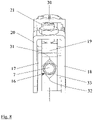
- Fig. 5:
- teilweise geschnitten den Setzkopf mit Stößel in einer Ruheposition,
- Fig. 6:
- den Setzkopf nach Setzen eines Dübels,
- Fig. 7:
- den Setzkopf mit geöffneter Klappe und
- Fig. 8:
- eine vergrößerte frontseitige Ansicht des Setzkopfes.
- Die Vorrichtung 1 gemäß den
Figuren 1 bis 4 weist einen massiven Träger 2 auf, der seitlich und unterseitig mit Langlöchern 3,4 versehen ist. Diese Langlöcher erlauben es, den Träger 2 auf einem weiter nicht dargestellten Maschinenbett vor einem lediglich angedeuteten Werkstück 5 zu positionieren und damit die Einbringtiefe eines Dübels in das Werkstück 5 zu bestimmen. - Hin zu dem Werkstück 5 steht ein Setzkopf 6 dem Träger 2 vor. Rückseitig weist der Setzkopf 6 eine Durchbrechung auf, die von einem Stößel 7 durchsetzt wird, der über ein Koppelstück 8 an den Kolben 9 eines Zylinders 10 angeschlossen ist. Der Zylinder 10 stützt sich entgegengesetzt der Eintragsrichtung eines Dübels gemäß Pfeil 11 an einem auf der Oberseite 12 des Trägers 2 festgelegten, plattenartigen Anschlag 13 ab.
- Bei dem Ausführungsbeispiel sind der Setzkopf 6 und der Zylinder 10 mit Kolben 9, Koppelstück 8 und Stößel 7 außermittig auf der Oberseite 12 des Trägers 2 angeordnet. Wird die Vorrichtung 1 neben einer weiteren, spiegelbildlich ausgebildete Vorrichtung platziert, lassen sich Dübel gleichzeitig in einem sehr geringen Abstand in ein Werkstück einbringen, ohne dass der Träger 2 seine Stabilität einbüßt.
- Der Setzkopf 6 ist über ein Distanzstück 15 auf der Oberseite 12 des Trägers 2 festgelegt, womit eine Führung 16 für das Führen eines Dübels bei dessen Einbringen mit dem Stößel 7 fluchtet.
- Der Setzkopf 6 weist zwei Seitenteile 17,18 auf, zwischen denen eine nach oben verschwenkbare Klappe 19 angeordnet ist. Während des Setzens eines Dübels ist die Klappe 19 geschlossen und wird von einem verschwenkbaren Bügel 20 verriegelt. Dieses Verriegeln erfolgt unter der Kraft einer Feder eines Federdruckstücks 21. Um ein sicheres Verriegeln der Klappe 19 sicherzustellen, weist diese einen Anschlag 22 für den Bügel 20 auf und eine sich in einer Ebene senkrecht zu dem Federdruckstück 21 erstreckende Auflagefläche 23 auf, vergleiche
Figur 7 . - Die Zuführung eines Dübels erfolgt beispielsweise über einen nicht dargestellten Schlauch, der mittels eines Klemmrings 24 an dem Setzkopf 6 angeschlossen ist. Ein solcher Schlauch kann von einem rückseitig des Trägers 2 angebrachten Profil 25 exakt über der Vorrichtung 1 gehalten werden.
- Ein solchermaßen zugeführter Dübel tritt durch einen Führungskanal 26 in eine Aufnahme 27 ein, die oberseitig von einer von der Innenseite der Klappe 19 gebildeten Führungsbahn 28 begrenzt wird. Verläuft diese Führungsbahn 28 zunächst in einer Flucht mit dem Führungskanal 26, so weist sie hin zu der Vorderseite des Setzkopfes 6 einen nach unten gekrümmten Abschnitt 29 auf. Befindet sich in der Aufnahme 27 ein Dübel, wird der Stößel 7 durch den Zylinder 10 aus seiner Ruheposition gemäß
Figur 5 nach vorn verbracht, vergleicheFigur 6 , und damit der Dübel in das Werkstück 5 eingebracht. - Für dieses Einbringen eines Dübels in eine Bohrung in einem Werkstück 5 ist die Führung 16 vorgesehen, vergleiche
Figur 8 . Diese Führung 16 für das Einbringen eines Dübels in das Werkstück 5 weist bei dem Ausführungsbeispiel den Querschnitt eines Quadrats auf. Mit Bezug auf eine Mittelebene 30 werden durch das Viereck der Führung 16 Ecken 31,32 ausgebildet. Mithin öffnet sich die Führung 16 hin zu einer Achse des Stößels 7 V-förmig. Die Führung 16 ist weiter in einer mittigen, sich horizontal erstreckenden Ebene geteilt. In dem Unterteil 33 werden damit Dübel kleinerer Durchmesser in der V-förmigen Ausnehmung des Unterteils 33 ausreichend sicher noch geführt.
Claims (7)
- Auf einem Träger angeordnete Vorrichtung für das Einbringen von Dübeln in vorgebohrte Werkstücke, wobei hin zu dem Werkstück (5) ein dem Träger (2) vorstehender Setzkopf (6) vorgesehen ist, der eine Aufnahme (27) für einen zugeführten Dübel und eine Führung (16) für das Einbringen des Dübels in die Bohrung des Werkstücks (5) aufweist, wobei der Setzkopf (6) oder die Führung (16) auswechselbar ist, wobei der Setzkopf (6) in einer Flucht mit der Führung (16) eine rückwärtige Durchbrechung aufweist, die von einem Kolben oder einem an den Kolben angeschlossenen Stößel (7) eines Zylinders (10) durchsetzt wird, wobei der Setzkopf (6) zwei Seitenteile (17,18) aufweist, zwischen denen eine nach oben verschwenkbare Klappe (19) angeordnet ist und wobei die Innenseite der Klappe (19) eine Führungsbahn (28) für das Zuführen eines Dübels mit ausbildet.
- Vorrichtung nach Anspruch 1, dadurch gekennzeichnet, dass der Träger (2) massiv ausgebildet und in seiner Längserstreckung mit Langlöchern (4,5) versehen ist.
- Vorrichtung nach einem oder mehreren der vorangehenden Ansprüche, dadurch gekennzeichnet, dass sich der Zylinder (10) gegen einen trägerfesten Anschlag (13) abstützt.
- Vorrichtung nach einem oder mehreren der vorangehenden Ansprüche, dadurch gekennzeichnet, dass die geschlossene Klappe (19) von einem verschwenkbaren Bügel (20) unter Spannung einer Feder verriegelt ist.
- Vorrichtung nach einem oder mehreren der vorangehenden Ansprüche, dadurch gekennzeichnet, dass die Führung (16) für das Einbringen des Dübels in das Werkstück den Querschnitt eines regelmäßigen Vielecks aufweist.
- Vorrichtung nach Anspruch 5, dadurch gekennzeichnet, dass die Führung mittig ober- und unterseitig eine Ecke (31,32) aufweist.
- Vorrichtung nach Anspruch 5 oder 6, dadurch gekennzeichnet, dass die Führung in einer mittigen horizontalen Ebene geteilt ist.
Applications Claiming Priority (1)
| Application Number | Priority Date | Filing Date | Title |
|---|---|---|---|
| DE102019003589.5A DE102019003589A1 (de) | 2019-05-22 | 2019-05-22 | Vorrichtung für das Einbringen von Dübeln in Werkstücke |
Publications (2)
| Publication Number | Publication Date |
|---|---|
| EP3744481A1 EP3744481A1 (de) | 2020-12-02 |
| EP3744481B1 true EP3744481B1 (de) | 2023-01-25 |
Family
ID=70740389
Family Applications (1)
| Application Number | Title | Priority Date | Filing Date |
|---|---|---|---|
| EP20000188.1A Active EP3744481B1 (de) | 2019-05-22 | 2020-05-15 | Vorrichtung für das einbringen von dübeln in werkstücke |
Country Status (4)
| Country | Link |
|---|---|
| EP (1) | EP3744481B1 (de) |
| DE (1) | DE102019003589A1 (de) |
| LT (1) | LT3744481T (de) |
| PL (1) | PL3744481T3 (de) |
Families Citing this family (1)
| Publication number | Priority date | Publication date | Assignee | Title |
|---|---|---|---|---|
| DE102022003786A1 (de) | 2022-10-13 | 2024-04-18 | Gerhard Koch Maschinenfabrik Gmbh & Co. Kg | Vorrichtung und Verfahren für das Setzen von Pilzkopf Dübeln |
Family Cites Families (4)
| Publication number | Priority date | Publication date | Assignee | Title |
|---|---|---|---|---|
| DE2432642A1 (de) * | 1974-07-08 | 1976-01-29 | Hilti Ag | Verfahren und geraet zum setzen eines duebels |
| DE3437849A1 (de) * | 1984-10-16 | 1986-04-24 | Hilti Ag, Schaan | Werkzeug zum einfuehren von duebeln |
| US4858811A (en) * | 1985-11-21 | 1989-08-22 | Eldorado Cartridge Corporation | Power actuated tool with magazine feed |
| DE3602542A1 (de) * | 1986-01-29 | 1987-07-30 | Hoffmann Duebelfix Maschinenba | Vorrichtung zum eintreiben von duebeln in duebelloecher von werkstuecken |
-
2019
- 2019-05-22 DE DE102019003589.5A patent/DE102019003589A1/de not_active Withdrawn
-
2020
- 2020-05-15 LT LTEP20000188.1T patent/LT3744481T/lt unknown
- 2020-05-15 EP EP20000188.1A patent/EP3744481B1/de active Active
- 2020-05-15 PL PL20000188.1T patent/PL3744481T3/pl unknown
Also Published As
| Publication number | Publication date |
|---|---|
| DE102019003589A1 (de) | 2020-11-26 |
| EP3744481A1 (de) | 2020-12-02 |
| LT3744481T (lt) | 2023-05-10 |
| PL3744481T3 (pl) | 2023-05-29 |
Similar Documents
| Publication | Publication Date | Title |
|---|---|---|
| DE102017105016B3 (de) | Lagervorrichtung | |
| DE202012103274U1 (de) | Bohrformhalter zur Fertigung von Tischlerei-Schrägbohrungen und denselben enthaltender Bausatz | |
| EP3744481A1 (de) | Vorrichtung für das einbringen von dübeln in werkstücke | |
| EP3722068A1 (de) | Auswerfstift mit verdrehsicherung | |
| DE2637085C3 (de) | Vorrichtung zum Ausstoßen des Stanzabfalles oder Stanzteils mittels Druckluft | |
| DE3833742A1 (de) | Einspannvorrichtung | |
| EP1747875B1 (de) | Vorrichtung zum Stapeln von Teilen aus thermoplastischem Kunststoff | |
| DE2440999A1 (de) | Schnitt- und stanzwerkzeug | |
| DE2713842C2 (de) | Schweißvorrichtung zum Schweißen der Kanten von Blechtüren | |
| DE4131942C2 (de) | Vorrichtung zur Spieleinstellung der Messer einer Schneidmaschine | |
| DE2166857A1 (de) | Montagevorrichtung fuer moebelbeschlaege, insbesondere scharniere | |
| DE102016108880A1 (de) | Hybridsetter | |
| EP3689545A1 (de) | Spannbacke zum spannen eines werkstücks | |
| EP1378331B1 (de) | Anschlagmaschine | |
| DE9318967U1 (de) | Werkzeug für eine Presse oder Stanze und C-Gestell-Presse oder -Stanze mit dem Werkzeug | |
| DE19913458A1 (de) | Werkstückhaltevorrichtung | |
| DE102022003786A1 (de) | Vorrichtung und Verfahren für das Setzen von Pilzkopf Dübeln | |
| DE102008020804B4 (de) | Einrichtung zur Bereitstellung von Werkstücken, insbsondere Zahnräder | |
| DE60106807T2 (de) | Verfahren und Vorrichtung zum Einsetzen von Halbkegeln in der konischen Aussparung eines Federtellers | |
| DE3316356A1 (de) | Vorrichtung zum einsetzen von beschlagschienen | |
| DE2947260A1 (de) | Bohrmaschine | |
| DE10212216A1 (de) | Bearbeitungszentrum mit Bearbeitungseinheit und Versorgungseinheit | |
| DE7119967U (de) | Bohr- und Einpressvorrichtung für in Möbelteilen zu befestigende Möbelbeschläge, insbesondere Topfbandscharniere | |
| DE3305210A1 (de) | Handbohrgeraet mit einer bohrlehre zum setzen von duebelloechern | |
| DE102019000029A1 (de) | Vorrichtung zum Umformen von Holzfurnierrohlingen |
Legal Events
| Date | Code | Title | Description |
|---|---|---|---|
| PUAI | Public reference made under article 153(3) epc to a published international application that has entered the european phase |
Free format text: ORIGINAL CODE: 0009012 |
|
| STAA | Information on the status of an ep patent application or granted ep patent |
Free format text: STATUS: THE APPLICATION HAS BEEN PUBLISHED |
|
| AK | Designated contracting states |
Kind code of ref document: A1 Designated state(s): AL AT BE BG CH CY CZ DE DK EE ES FI FR GB GR HR HU IE IS IT LI LT LU LV MC MK MT NL NO PL PT RO RS SE SI SK SM TR |
|
| AX | Request for extension of the european patent |
Extension state: BA ME |
|
| STAA | Information on the status of an ep patent application or granted ep patent |
Free format text: STATUS: REQUEST FOR EXAMINATION WAS MADE |
|
| 17P | Request for examination filed |
Effective date: 20210422 |
|
| GRAP | Despatch of communication of intention to grant a patent |
Free format text: ORIGINAL CODE: EPIDOSNIGR1 |
|
| STAA | Information on the status of an ep patent application or granted ep patent |
Free format text: STATUS: GRANT OF PATENT IS INTENDED |
|
| RIC1 | Information provided on ipc code assigned before grant |
Ipc: B25B 27/02 20060101ALI20221007BHEP Ipc: B25B 31/00 20060101ALI20221007BHEP Ipc: B25B 27/06 20060101AFI20221007BHEP |
|
| GRAS | Grant fee paid |
Free format text: ORIGINAL CODE: EPIDOSNIGR3 |
|
| INTG | Intention to grant announced |
Effective date: 20221115 |
|
| GRAA | (expected) grant |
Free format text: ORIGINAL CODE: 0009210 |
|
| STAA | Information on the status of an ep patent application or granted ep patent |
Free format text: STATUS: THE PATENT HAS BEEN GRANTED |
|
| AK | Designated contracting states |
Kind code of ref document: B1 Designated state(s): AL AT BE BG CH CY CZ DE DK EE ES FI FR GB GR HR HU IE IS IT LI LT LU LV MC MK MT NL NO PL PT RO RS SE SI SK SM TR |
|
| REG | Reference to a national code |
Ref country code: GB Ref legal event code: FG4D Free format text: NOT ENGLISH |
|
| REG | Reference to a national code |
Ref country code: CH Ref legal event code: EP |
|
| REG | Reference to a national code |
Ref country code: AT Ref legal event code: REF Ref document number: 1545612 Country of ref document: AT Kind code of ref document: T Effective date: 20230215 Ref country code: IE Ref legal event code: FG4D Free format text: LANGUAGE OF EP DOCUMENT: GERMAN |
|
| REG | Reference to a national code |
Ref country code: DE Ref legal event code: R096 Ref document number: 502020002417 Country of ref document: DE |
|
| REG | Reference to a national code |
Ref country code: RO Ref legal event code: EPE |
|
| REG | Reference to a national code |
Ref country code: NL Ref legal event code: MP Effective date: 20230125 |
|
| PG25 | Lapsed in a contracting state [announced via postgrant information from national office to epo] |
Ref country code: NL Free format text: LAPSE BECAUSE OF FAILURE TO SUBMIT A TRANSLATION OF THE DESCRIPTION OR TO PAY THE FEE WITHIN THE PRESCRIBED TIME-LIMIT Effective date: 20230125 |
|
| PG25 | Lapsed in a contracting state [announced via postgrant information from national office to epo] |
Ref country code: RS Free format text: LAPSE BECAUSE OF FAILURE TO SUBMIT A TRANSLATION OF THE DESCRIPTION OR TO PAY THE FEE WITHIN THE PRESCRIBED TIME-LIMIT Effective date: 20230125 Ref country code: PT Free format text: LAPSE BECAUSE OF FAILURE TO SUBMIT A TRANSLATION OF THE DESCRIPTION OR TO PAY THE FEE WITHIN THE PRESCRIBED TIME-LIMIT Effective date: 20230525 Ref country code: NO Free format text: LAPSE BECAUSE OF FAILURE TO SUBMIT A TRANSLATION OF THE DESCRIPTION OR TO PAY THE FEE WITHIN THE PRESCRIBED TIME-LIMIT Effective date: 20230425 Ref country code: LV Free format text: LAPSE BECAUSE OF FAILURE TO SUBMIT A TRANSLATION OF THE DESCRIPTION OR TO PAY THE FEE WITHIN THE PRESCRIBED TIME-LIMIT Effective date: 20230125 Ref country code: HR Free format text: LAPSE BECAUSE OF FAILURE TO SUBMIT A TRANSLATION OF THE DESCRIPTION OR TO PAY THE FEE WITHIN THE PRESCRIBED TIME-LIMIT Effective date: 20230125 Ref country code: ES Free format text: LAPSE BECAUSE OF FAILURE TO SUBMIT A TRANSLATION OF THE DESCRIPTION OR TO PAY THE FEE WITHIN THE PRESCRIBED TIME-LIMIT Effective date: 20230125 |
|
| PG25 | Lapsed in a contracting state [announced via postgrant information from national office to epo] |
Ref country code: SE Free format text: LAPSE BECAUSE OF FAILURE TO SUBMIT A TRANSLATION OF THE DESCRIPTION OR TO PAY THE FEE WITHIN THE PRESCRIBED TIME-LIMIT Effective date: 20230125 Ref country code: IS Free format text: LAPSE BECAUSE OF FAILURE TO SUBMIT A TRANSLATION OF THE DESCRIPTION OR TO PAY THE FEE WITHIN THE PRESCRIBED TIME-LIMIT Effective date: 20230525 Ref country code: GR Free format text: LAPSE BECAUSE OF FAILURE TO SUBMIT A TRANSLATION OF THE DESCRIPTION OR TO PAY THE FEE WITHIN THE PRESCRIBED TIME-LIMIT Effective date: 20230426 Ref country code: FI Free format text: LAPSE BECAUSE OF FAILURE TO SUBMIT A TRANSLATION OF THE DESCRIPTION OR TO PAY THE FEE WITHIN THE PRESCRIBED TIME-LIMIT Effective date: 20230125 |
|
| REG | Reference to a national code |
Ref country code: DE Ref legal event code: R097 Ref document number: 502020002417 Country of ref document: DE |
|
| PG25 | Lapsed in a contracting state [announced via postgrant information from national office to epo] |
Ref country code: SM Free format text: LAPSE BECAUSE OF FAILURE TO SUBMIT A TRANSLATION OF THE DESCRIPTION OR TO PAY THE FEE WITHIN THE PRESCRIBED TIME-LIMIT Effective date: 20230125 Ref country code: EE Free format text: LAPSE BECAUSE OF FAILURE TO SUBMIT A TRANSLATION OF THE DESCRIPTION OR TO PAY THE FEE WITHIN THE PRESCRIBED TIME-LIMIT Effective date: 20230125 Ref country code: DK Free format text: LAPSE BECAUSE OF FAILURE TO SUBMIT A TRANSLATION OF THE DESCRIPTION OR TO PAY THE FEE WITHIN THE PRESCRIBED TIME-LIMIT Effective date: 20230125 Ref country code: CZ Free format text: LAPSE BECAUSE OF FAILURE TO SUBMIT A TRANSLATION OF THE DESCRIPTION OR TO PAY THE FEE WITHIN THE PRESCRIBED TIME-LIMIT Effective date: 20230125 |
|
| PG25 | Lapsed in a contracting state [announced via postgrant information from national office to epo] |
Ref country code: SK Free format text: LAPSE BECAUSE OF FAILURE TO SUBMIT A TRANSLATION OF THE DESCRIPTION OR TO PAY THE FEE WITHIN THE PRESCRIBED TIME-LIMIT Effective date: 20230125 |
|
| PLBE | No opposition filed within time limit |
Free format text: ORIGINAL CODE: 0009261 |
|
| STAA | Information on the status of an ep patent application or granted ep patent |
Free format text: STATUS: NO OPPOSITION FILED WITHIN TIME LIMIT |
|
| REG | Reference to a national code |
Ref country code: CH Ref legal event code: PL |
|
| 26N | No opposition filed |
Effective date: 20231026 |
|
| PG25 | Lapsed in a contracting state [announced via postgrant information from national office to epo] |
Ref country code: MC Free format text: LAPSE BECAUSE OF FAILURE TO SUBMIT A TRANSLATION OF THE DESCRIPTION OR TO PAY THE FEE WITHIN THE PRESCRIBED TIME-LIMIT Effective date: 20230125 |
|
| REG | Reference to a national code |
Ref country code: BE Ref legal event code: MM Effective date: 20230531 |
|
| PG25 | Lapsed in a contracting state [announced via postgrant information from national office to epo] |
Ref country code: SI Free format text: LAPSE BECAUSE OF FAILURE TO SUBMIT A TRANSLATION OF THE DESCRIPTION OR TO PAY THE FEE WITHIN THE PRESCRIBED TIME-LIMIT Effective date: 20230125 Ref country code: MC Free format text: LAPSE BECAUSE OF FAILURE TO SUBMIT A TRANSLATION OF THE DESCRIPTION OR TO PAY THE FEE WITHIN THE PRESCRIBED TIME-LIMIT Effective date: 20230125 Ref country code: LU Free format text: LAPSE BECAUSE OF NON-PAYMENT OF DUE FEES Effective date: 20230515 Ref country code: LI Free format text: LAPSE BECAUSE OF NON-PAYMENT OF DUE FEES Effective date: 20230531 Ref country code: CH Free format text: LAPSE BECAUSE OF NON-PAYMENT OF DUE FEES Effective date: 20230531 |
|
| REG | Reference to a national code |
Ref country code: IE Ref legal event code: MM4A |
|
| PG25 | Lapsed in a contracting state [announced via postgrant information from national office to epo] |
Ref country code: IE Free format text: LAPSE BECAUSE OF NON-PAYMENT OF DUE FEES Effective date: 20230515 |
|
| PG25 | Lapsed in a contracting state [announced via postgrant information from national office to epo] |
Ref country code: IE Free format text: LAPSE BECAUSE OF NON-PAYMENT OF DUE FEES Effective date: 20230515 |
|
| PG25 | Lapsed in a contracting state [announced via postgrant information from national office to epo] |
Ref country code: BE Free format text: LAPSE BECAUSE OF NON-PAYMENT OF DUE FEES Effective date: 20230531 |
|
| PG25 | Lapsed in a contracting state [announced via postgrant information from national office to epo] |
Ref country code: BG Free format text: LAPSE BECAUSE OF FAILURE TO SUBMIT A TRANSLATION OF THE DESCRIPTION OR TO PAY THE FEE WITHIN THE PRESCRIBED TIME-LIMIT Effective date: 20230125 |
|
| PG25 | Lapsed in a contracting state [announced via postgrant information from national office to epo] |
Ref country code: BG Free format text: LAPSE BECAUSE OF FAILURE TO SUBMIT A TRANSLATION OF THE DESCRIPTION OR TO PAY THE FEE WITHIN THE PRESCRIBED TIME-LIMIT Effective date: 20230125 |
|
| GBPC | Gb: european patent ceased through non-payment of renewal fee |
Effective date: 20240515 |
|
| PGFP | Annual fee paid to national office [announced via postgrant information from national office to epo] |
Ref country code: PL Payment date: 20250312 Year of fee payment: 6 |
|
| PG25 | Lapsed in a contracting state [announced via postgrant information from national office to epo] |
Ref country code: GB Free format text: LAPSE BECAUSE OF NON-PAYMENT OF DUE FEES Effective date: 20240515 |
|
| PGFP | Annual fee paid to national office [announced via postgrant information from national office to epo] |
Ref country code: IT Payment date: 20250325 Year of fee payment: 6 |
|
| PGFP | Annual fee paid to national office [announced via postgrant information from national office to epo] |
Ref country code: DE Payment date: 20250313 Year of fee payment: 6 |
|
| PGFP | Annual fee paid to national office [announced via postgrant information from national office to epo] |
Ref country code: LT Payment date: 20250416 Year of fee payment: 6 |
|
| PGFP | Annual fee paid to national office [announced via postgrant information from national office to epo] |
Ref country code: FR Payment date: 20250528 Year of fee payment: 6 |
|
| PGFP | Annual fee paid to national office [announced via postgrant information from national office to epo] |
Ref country code: RO Payment date: 20250428 Year of fee payment: 6 Ref country code: AT Payment date: 20250312 Year of fee payment: 6 |
|
| PG25 | Lapsed in a contracting state [announced via postgrant information from national office to epo] |
Ref country code: CY Free format text: LAPSE BECAUSE OF FAILURE TO SUBMIT A TRANSLATION OF THE DESCRIPTION OR TO PAY THE FEE WITHIN THE PRESCRIBED TIME-LIMIT; INVALID AB INITIO Effective date: 20200515 |
|
| PG25 | Lapsed in a contracting state [announced via postgrant information from national office to epo] |
Ref country code: HU Free format text: LAPSE BECAUSE OF FAILURE TO SUBMIT A TRANSLATION OF THE DESCRIPTION OR TO PAY THE FEE WITHIN THE PRESCRIBED TIME-LIMIT; INVALID AB INITIO Effective date: 20200515 |
|
| PG25 | Lapsed in a contracting state [announced via postgrant information from national office to epo] |
Ref country code: TR Free format text: LAPSE BECAUSE OF FAILURE TO SUBMIT A TRANSLATION OF THE DESCRIPTION OR TO PAY THE FEE WITHIN THE PRESCRIBED TIME-LIMIT Effective date: 20230125 |