EP3745032B1 - Dunstabzugshaube mit mitteln zum erzeugen von zwei lichtkegeln und küchenabschnitt mit dunstabzugshaube - Google Patents
Dunstabzugshaube mit mitteln zum erzeugen von zwei lichtkegeln und küchenabschnitt mit dunstabzugshaube Download PDFInfo
- Publication number
- EP3745032B1 EP3745032B1 EP20174643.5A EP20174643A EP3745032B1 EP 3745032 B1 EP3745032 B1 EP 3745032B1 EP 20174643 A EP20174643 A EP 20174643A EP 3745032 B1 EP3745032 B1 EP 3745032B1
- Authority
- EP
- European Patent Office
- Prior art keywords
- light
- extractor hood
- light cone
- cones
- kitchen
- Prior art date
- Legal status (The legal status is an assumption and is not a legal conclusion. Google has not performed a legal analysis and makes no representation as to the accuracy of the status listed.)
- Active
Links
Images


Classifications
-
- F—MECHANICAL ENGINEERING; LIGHTING; HEATING; WEAPONS; BLASTING
- F24—HEATING; RANGES; VENTILATING
- F24C—DOMESTIC STOVES OR RANGES ; DETAILS OF DOMESTIC STOVES OR RANGES, OF GENERAL APPLICATION
- F24C15/00—Details
- F24C15/20—Removing cooking fumes
- F24C15/2064—Removing cooking fumes illumination for cooking hood
Definitions
- the extractor hoods have a lighting unit that illuminates a cooking surface located beneath the extractor hood.
- a lighting unit that illuminates a cooking surface located beneath the extractor hood.
- Such an extractor hood is, for example, US 2015/184869 A1 revealed.
- the US 2019/114935 A1 discloses a cooking connection system for a cooking appliance.
- the system may include a camera assembly, an image monitor, a lighting assembly, and a controller.
- the lighting assembly may be arranged on the housing above the cooking appliance.
- the lighting assembly may include a light source directed toward the cooking surface to direct light thereto.
- the GB 2 486 507 A A range hood with duct lighting.
- the range hood has a duct and light sources that project light onto the duct.
- the light source can be part of the fan housing and project downwards onto the hood or upwards from the hood housing.
- the lighting device comprises an additional lighting module with at least one first additional lighting element for illuminating the first section and at least one second additional lighting element for illuminating the second section, as well as a control unit for adjusting a brightness in the lighting area by controlling the lighting module and/or the additional lighting module.
- At least a first and a second light cone are generated.
- the designations "first” and “second” serve only to facilitate reference to the light cones and do not represent a temporal designation.
- the at least one first light cone is emitted in a direction directed downward toward the surface of the vertical projection of the extractor hood.
- a hob is generally arranged in the surface of the vertical projection or at least in the plane of the surface of the vertical downward projection of the extractor hood.
- the at least one first light cone is directed downward toward the hob.
- the light cone can be vertically aligned, meaning its radiation direction can be perpendicular, or the radiation direction can be inclined relative to the vertical.
- the means for generating the at least two light cones are also adapted such that the second of the at least two light cones is emitted rearward or to the side.
- the second of the at least two light cones is emitted in a direction whose horizontal component points toward a plane in which the rear or one of the two side surfaces of the extractor hood lies.
- the plane in which the rear side or one of the two side surfaces lies can be understood as an extension of the rear side or the corresponding side surface of the extractor hood. If the extractor hood is mounted with its rear side against a room wall, the plane in which the rear side lies can essentially correspond to this room wall. If the extractor hood is mounted in such a way that the rear wall is mounted close to, preferably within 1 m, 0.5 m or 0.2 m of, the room wall, whereby the room wall is preferably essentially parallel to the rear wall of the extractor hood, the said plane can also be understood as Room wall.
- the direction, origin, intensity distribution as a function of the radiation direction, and the shape of the emitted light are referred to as the light cone.
- this term is not intended to limit the shape, intensity distribution, direction, or effect of the emitted light to an exact cone shape. Rather, the term "light cone” refers to a rough description of the light emitted by the medium.
- the light cone used to describe the emitted light has a directional vector and an aperture angle.
- the direction of the light cone is generally understood to be the direction of the axis.
- the maximum luminous flux of the light cone preferably lies along this axis.
- the means for generating the at least two light cones can be adapted, for example, by their structure, orientation and/or position on the extractor hood to generate the specifically aligned light cones.
- the means for generating at least two light cones are adapted such that the first and second light cones emit light at least partially downwards and at least one of the light cones, in particular the second light cone, also emits the light in a direction facing backwards and/or to one side.
- This makes it possible to illuminate, on the one hand, an area below the extractor hood, in particular a hob, and, on the other hand, a surrounding area, for example a room wall behind or next to the hob.
- This makes it possible to direct focused light onto the hob, which at the same time creates a positive subjective impression of bright light, like that of a wide-angle spotlight.
- the second light cone which is directed onto a room wall behind or next to the hob, can reduce the difference in brightness between cooking vessels on the hob and the room wall, thereby improving the user experience of the extractor hood.
- the means for generating at least two light cones comprise a lighting unit.
- the lighting unit has a single light source.
- a lighting unit is particularly referred to as a unit that is arranged on or in the extractor hood, in particular on or in an extractor housing or a viewing hood of the extractor hood.
- the lighting unit is preferably provided on or in the extractor hood in such a way that it can illuminate a space outside the extractor housing.
- this is preferably a lighting unit with which an area in the vicinity of an extractor hood and/or the area of another kitchen appliance can be at least partially illuminated or illuminated.
- the environment of an extractor hood or a kitchen appliance is the room in which the extractor hood or the kitchen appliance is operated.
- the lighting device has only a single light source.
- this single light source the at least two light cones can be generated by extracting a portion of the light emitted by the light source.
- an optical system is used, which, for example, has a diaphragm and/or a reflector. This simplifies the design of the lighting unit and thus of the extractor hood. Furthermore, the power consumption is reduced.
- the means for generating the at least two light cones are adapted such that the first of the at least two light cones is emitted such that it illuminates a plane located at a predetermined vertical distance below the extractor hood.
- This plane is preferably horizontal.
- the predetermined vertical distance is preferably within a predetermined or recommended distance range of the extractor hood to the kitchen work surface below or to a hob arranged below.
- the predetermined vertical distance can be in the range of 0.4 m to 2 m, particularly preferably 0.5 m to 1 m, or 0.6 m to 0.8 m.
- only a limited area of this plane is irradiated by the first of the two light cones.
- an area measuring 1m x 1m and located vertically under the extractor hood or an area measuring 0.6m x 0.6m and located vertically under the extractor hood and/or an area corresponding to the area of a hob or conventional hob that is arranged under the extractor hood.
- the means for generating the light cones are designed so that the second light cone is emitted in such a way that it covers the plane in which the rear or one of the two side surfaces of the extractor hood, within the intended vertical distance. Illuminating a wall that lies in one of these planes, at the vertical distance, i.e., particularly between the extractor hood and a hob, is advantageous because room walls are often light-colored and therefore reflect a lot of light. Furthermore, room walls are often matte and have good scattering properties. This allows the light to scatter back, which can make the lighting appear bright.
- the first and second of the at least two light cones can be substantially separate, i.e., they do not overlap, preferably only insignificantly, or such that a visible darker region, preferably a local minimum or saddle point of the luminance, is recognizable between the light cones.
- the means for generating the at least two light cones are adapted such that the at least two light cones are emitted such that the sum of the luminous intensities of the at least two light cones, as a function of the emission direction, has a saddle point between the direction of the maximum of the first and the direction of the maximum of the second of the at least two light cones.
- the sum of the luminous intensities of the first and second light cones at the saddle point is less than 10% of the maximum luminous intensity of the first light cone, preferably less than 1% of the maximum luminous intensity of the first light cone.
- the light cones may overlap.
- the light cones only overlap partially.
- the first light cone can be focused on the hob to provide particularly bright illumination. of the hob.
- the second light cone can point in a similar or the same direction and advantageously also illuminate a rear and/or side wall.
- the generated light cones have an inner light cone region and the means for generating the at least two light cones are adapted such that the inner light cone region of the first light cone and the inner light cone region of the second light cone do not overlap.
- the inner light cone area is an area in which the luminous flux in the light cone is greater than in an outer light cone area.
- the inner light cone regions that do not overlap are very bright light cone regions that contain 80% of the luminous flux of the entire light cone.
- the very bright light cone region is understood to be a conical region that has the same tip and the same axis as the generated light cone, and whose aperture angle is selected such that the cone region contains 80% of the luminous flux. This means that 80% of the luminous flux is emitted in the inner very bright light cone region and strikes the surface to be irradiated.
- the inner light cone regions that do not overlap are bright light cone regions that contain 98% of the luminous flux of the entire light cone.
- the bright light cone region is understood to be a conical region that has the same tip and the same axis as the generated light cone, and whose opening angle is selected such that the cone region 98% of the luminous flux. This means that 98% of the luminous flux is emitted in the inner bright light cone area and hits the surface to be illuminated.
- the means for generating the at least two light cones are adapted such that the aperture angle of the first light cone is less than 90°, preferably less than 70°, and particularly preferably less than 45°.
- a hob located beneath the extractor hood is illuminated with high luminance.
- the aperture angle of the second light cone is larger than that of the first light cone in order to illuminate additional surfaces, which preferably have different reflection and/or scattering properties, and particularly preferably have a higher scattering.
- additional surfaces which preferably have different reflection and/or scattering properties, and particularly preferably have a higher scattering.
- one of these surfaces is a rear and/or side wall. This leads to a subjectively brighter perception of the illumination by an observer.
- the means for generating at least two light cones are adapted such that the aperture angle of the second light cone is less than 120°, preferably between 45° and 120°, and particularly preferably between 45° and 90°.
- An advantage of this embodiment may be that the area surrounding the hob, such as a rear wall or side wall, is optimally illuminated.
- the means for generating the at least two light cones are adapted such that the ratio of the luminous flux of the first to the luminous flux of the second of the at least two light cones is between 1:1 and 20:1, preferably between 7:3 and 9:1, and particularly preferably between 4:1 and 8:1.
- the majority of the luminous flux is used to illuminate an area beneath the extractor hood, such as a hob.
- the overall lighting is improved by illuminating other areas, such as the brightness of the lighting perceived by an observer or the contrast between objects illuminated by the first light cone and objects or surfaces illuminated by the second light cone.
- the means for generating the at least two light cones are adapted so that the angle of inclination of the first light cone of the The vertical axis in the positive y-direction is between -35° and 35°, preferably between -20° and 20°, and particularly preferably vertical.
- the advantage here is that the angled position directs the light cone onto a hob located beneath the extractor hood.
- the means for generating at least two light cones are adapted such that the angle of inclination of the second light cone from the vertical axis in the positive y-direction is between -80° and 0°, preferably between -80° and -20°, and particularly preferably between -80° and -45°.
- An advantage of this embodiment may be that this light cone illuminates a wall lying in the negative y-direction.
- the means for generating at least two light cones are adapted so that, in addition to the first and second light cones, further light cones are generated which can have essentially the same properties as the first or second light cone.
- the kitchen section comprises an extractor hood, a hob, a kitchen back wall and a kitchen side wall
- the extractor hood comprises means for generating at least three light cones
- the means for generating at least three light cones of the extractor hood are adapted such that the first of the at least three light cones is directed substantially towards the hob, the second of the at least three light cones is directed substantially towards a first kitchen side wall and the third of the at least three light cones is directed substantially towards the second kitchen side wall.
- the generated light cones have an inner bright light cone region which contains 98% of the luminous flux of the entire light cone, wherein the inner bright light cone region of the first light cone and the inner very bright light cone region of the second light cone do not overlap on the irradiated kitchen back wall and/or the kitchen side wall.
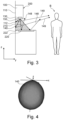
- FIG 4 A light cone (140) with a wide opening angle is shown schematically.
- the length of a line from the origin to the surface of the schematically shown light cone can be taken as a measure of the luminous intensity for this solid angle.
- Light cones with wide opening angles are particularly suitable for illuminating wide areas, including those around the hob.
- a light cone (140, 150) is shown schematically, which is generated by a light source (130).
- the radiation direction (146, 156) of the light cone is defined by the axis of the light cone (140, 150) and emanates from the tip of the light cone.
- the luminous intensity of the light cone (140, 150) decreases from the axis outwards.
- the light cone (140, 150) has a very bright inner light cone region (144, 154) near the center, which contains 80% of the total luminous intensity.
- the very bright inner light cone region (144, 154) is itself a cone with a smaller aperture angle, and with the same axis as that of the light cone (140, 150).
- the Light cone (140, 150) also has a bright inner light cone region (142, 152) near the center, which contains 98% of the total light intensity.
- the bright light cone region is itself a cone with a smaller aperture angle than light cone (140, 150) and a larger aperture angle than the very bright light cone region (146, 156), and with the same axis as those of light cone (140, 150) and the very bright inner light cone region (146, 156).
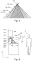
- the light cone (140) is emitted downwards/forwards, i.e. the vertical component of the direction of the light cone (140) is directed downwards and the horizontal component is directed forwards, so that the light cone (140) shines in the plane (222) within the intended vertical distance between the extractor hood (100) and the hob (220).
- Part of the light is reflected upwards by the hob (220), schematically represented by the arrows (148). Reflected rays follow the principle that the angle of incidence equals the angle of reflection. Therefore, the reflected first light cone shines over the user (B).
- the second light cone (150) is emitted in a direction (156) pointing backwards/downwards, i.e.
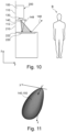
- FIG 9 A further embodiment of the extractor hood (100) according to the invention and the kitchen section (200) according to the invention is shown schematically.
- This embodiment differs, among other things, from the embodiment of Figure 7 in that the kitchen section has a kitchen side wall (230) instead of a kitchen back wall, which is illuminated by the second light cone (150).
- the lighting device (130) radiates the second light cone (150) in the -z/ -x direction such that the directional vector (156) of the second light cone (150) points to a plane (122) in which one of the side walls (120) of the extractor hood (100) lies.
- the light cone (150) strikes this plane (122) within a vertical distance from the hob (220) provided for the extractor hood (100).
- the directional vector (156) points to the kitchen side wall (230). This also achieves favorable lighting for a kitchen geometry in which the extractor hood (100) is arranged next to a kitchen side wall (230).
Landscapes
- Engineering & Computer Science (AREA)
- Chemical & Material Sciences (AREA)
- Combustion & Propulsion (AREA)
- Mechanical Engineering (AREA)
- General Engineering & Computer Science (AREA)
- Non-Portable Lighting Devices Or Systems Thereof (AREA)
Applications Claiming Priority (1)
| Application Number | Priority Date | Filing Date | Title |
|---|---|---|---|
| DE102019207966.0A DE102019207966A1 (de) | 2019-05-29 | 2019-05-29 | Dunstabzugshaube mit Mitteln zum Erzeugen von zwei Lichtkegeln und Küchenabschnitt mit Dunstabzugshaube |
Publications (2)
| Publication Number | Publication Date |
|---|---|
| EP3745032A1 EP3745032A1 (de) | 2020-12-02 |
| EP3745032B1 true EP3745032B1 (de) | 2025-07-09 |
Family
ID=70736697
Family Applications (1)
| Application Number | Title | Priority Date | Filing Date |
|---|---|---|---|
| EP20174643.5A Active EP3745032B1 (de) | 2019-05-29 | 2020-05-14 | Dunstabzugshaube mit mitteln zum erzeugen von zwei lichtkegeln und küchenabschnitt mit dunstabzugshaube |
Country Status (4)
| Country | Link |
|---|---|
| EP (1) | EP3745032B1 (pl) |
| DE (1) | DE102019207966A1 (pl) |
| ES (1) | ES3036109T3 (pl) |
| PL (1) | PL3745032T3 (pl) |
Families Citing this family (1)
| Publication number | Priority date | Publication date | Assignee | Title |
|---|---|---|---|---|
| EP4462030A4 (en) * | 2022-06-22 | 2025-05-28 | Samsung Electronics Co., Ltd | LIGHT SOURCE AND VENTILATION HOOD |
Family Cites Families (4)
| Publication number | Priority date | Publication date | Assignee | Title |
|---|---|---|---|---|
| GB201021019D0 (en) * | 2010-12-13 | 2011-01-26 | Degg Peter | Mood light cooker hood |
| TWM478783U (zh) | 2013-12-31 | 2014-05-21 | Long Industry Inc | 易拆裝之燈具結構 |
| DE102016111824A1 (de) * | 2016-06-28 | 2017-12-28 | Miele & Cie. Kg | Beleuchtungsvorrichtung zum Einbau in eine Dunstabzugshaube, Dunstabzugshaube und Verfahren zum Einstellen einer Helligkeit in einem Beleuchtungsbereich |
| US10796590B2 (en) * | 2017-10-13 | 2020-10-06 | Haier Us Appliance Solutions, Inc. | Cooking engagement system |
-
2019
- 2019-05-29 DE DE102019207966.0A patent/DE102019207966A1/de active Pending
-
2020
- 2020-05-14 ES ES20174643T patent/ES3036109T3/es active Active
- 2020-05-14 PL PL20174643.5T patent/PL3745032T3/pl unknown
- 2020-05-14 EP EP20174643.5A patent/EP3745032B1/de active Active
Also Published As
| Publication number | Publication date |
|---|---|
| PL3745032T3 (pl) | 2025-11-24 |
| DE102019207966A1 (de) | 2020-12-03 |
| EP3745032A1 (de) | 2020-12-02 |
| ES3036109T3 (en) | 2025-09-12 |
Similar Documents
| Publication | Publication Date | Title |
|---|---|---|
| DE4301936C2 (de) | Fahrzeugscheinwerfer mit zwei getrennten Beleuchtungseinheiten mit je einem Reflektor | |
| EP2031296B1 (de) | Beleuchtungsvorrichtung | |
| EP3752765B1 (de) | Kraftfahrzeugscheinwerfer mit einer abschirmblende zur abschirmung eintretender sonnenstrahlung | |
| WO2012038173A1 (de) | Leuchtvorrichtung | |
| EP0930600A1 (de) | Optikelement aus LED und zwei Linsen für die Erzeugung eines Lichtpunktes für Verkehrszeichen und Anzeigetafeln | |
| EP2984397B1 (de) | Leuchteinheit für einen fahrzeugscheinwerfer | |
| WO2021043544A1 (de) | Beleuchtungsvorrichtung für einen kraftfahrzeugscheinwerfer | |
| EP2401544A1 (de) | Fahrzeugleuchte | |
| DE102014202774B4 (de) | Deckenverkleidungselement für eine Innenverkleidungsanordnung einer Flugzeugkabine | |
| EP3745032B1 (de) | Dunstabzugshaube mit mitteln zum erzeugen von zwei lichtkegeln und küchenabschnitt mit dunstabzugshaube | |
| DE102015219211B4 (de) | Lichtmodul für eine Kfz-Beleuchtungseinrichtung | |
| EP3051213B1 (de) | Dunstabzugshaube | |
| DE102019123515B4 (de) | Kraftfahrzeugscheinwerfer mit zwei Projektionslichtmodulen unterschiedlicher Brennweite und gleich breit ausgeleuchteten Lichtaustrittslinsen | |
| DE102017219497A1 (de) | Gargerät mit einer Beleuchtungsvorrichtung zur Erzeugung eines gehäuseexternen Brennpunkts | |
| DE102016122188A1 (de) | Lichtvorrichtung, insbesondere ein Projektorsystem für einen Scheinwerfer für Kraftfahrzeuge | |
| EP3443268B1 (de) | Tür für ein haushaltsgerät und haushaltsgargerät | |
| EP0990579A2 (de) | Fahrzeugleuchte | |
| DE19811961B4 (de) | Fahrzeugscheinwerfer | |
| DE10258176B4 (de) | Beleuchtungsanordnung für Bedien- und/oder Anzeigeinstrumente | |
| WO2021099113A1 (de) | Dunstabzugsvorrichtung mit wrasenleitplatte und beleuchtungseinrichtung | |
| DE102017215892A1 (de) | Beleuchtungseinrichtung für ein Fahrzeug | |
| DE102019112343A1 (de) | Kraftfahrzeugleuchte | |
| WO2019086282A1 (de) | Gargerät mit einer beleuchtungsvorrichtung zum abstrahlen von lichtstrahlen mit unterschiedlichem lichtstrom in abhängigkeit von den betriebsfunktionen des gargeräts | |
| WO2017125225A1 (de) | Beleuchtungsvorrichtung für ein fahrzeug | |
| EP4063728A1 (de) | Leuchte |
Legal Events
| Date | Code | Title | Description |
|---|---|---|---|
| PUAI | Public reference made under article 153(3) epc to a published international application that has entered the european phase |
Free format text: ORIGINAL CODE: 0009012 |
|
| STAA | Information on the status of an ep patent application or granted ep patent |
Free format text: STATUS: THE APPLICATION HAS BEEN PUBLISHED |
|
| AK | Designated contracting states |
Kind code of ref document: A1 Designated state(s): AL AT BE BG CH CY CZ DE DK EE ES FI FR GB GR HR HU IE IS IT LI LT LU LV MC MK MT NL NO PL PT RO RS SE SI SK SM TR |
|
| AX | Request for extension of the european patent |
Extension state: BA ME |
|
| STAA | Information on the status of an ep patent application or granted ep patent |
Free format text: STATUS: REQUEST FOR EXAMINATION WAS MADE |
|
| 17P | Request for examination filed |
Effective date: 20210602 |
|
| RBV | Designated contracting states (corrected) |
Designated state(s): AL AT BE BG CH CY CZ DE DK EE ES FI FR GB GR HR HU IE IS IT LI LT LU LV MC MK MT NL NO PL PT RO RS SE SI SK SM TR |
|
| STAA | Information on the status of an ep patent application or granted ep patent |
Free format text: STATUS: EXAMINATION IS IN PROGRESS |
|
| 17Q | First examination report despatched |
Effective date: 20230119 |
|
| GRAP | Despatch of communication of intention to grant a patent |
Free format text: ORIGINAL CODE: EPIDOSNIGR1 |
|
| STAA | Information on the status of an ep patent application or granted ep patent |
Free format text: STATUS: GRANT OF PATENT IS INTENDED |
|
| INTG | Intention to grant announced |
Effective date: 20250206 |
|
| GRAS | Grant fee paid |
Free format text: ORIGINAL CODE: EPIDOSNIGR3 |
|
| GRAA | (expected) grant |
Free format text: ORIGINAL CODE: 0009210 |
|
| STAA | Information on the status of an ep patent application or granted ep patent |
Free format text: STATUS: THE PATENT HAS BEEN GRANTED |
|
| AK | Designated contracting states |
Kind code of ref document: B1 Designated state(s): AL AT BE BG CH CY CZ DE DK EE ES FI FR GB GR HR HU IE IS IT LI LT LU LV MC MK MT NL NO PL PT RO RS SE SI SK SM TR |
|
| REG | Reference to a national code |
Ref country code: GB Ref legal event code: FG4D Free format text: NOT ENGLISH |
|
| REG | Reference to a national code |
Ref country code: CH Ref legal event code: EP |
|
| REG | Reference to a national code |
Ref country code: IE Ref legal event code: FG4D Free format text: LANGUAGE OF EP DOCUMENT: GERMAN |
|
| REG | Reference to a national code |
Ref country code: DE Ref legal event code: R096 Ref document number: 502020011369 Country of ref document: DE |
|
| REG | Reference to a national code |
Ref country code: ES Ref legal event code: FG2A Ref document number: 3036109 Country of ref document: ES Kind code of ref document: T3 Effective date: 20250912 |
|
| REG | Reference to a national code |
Ref country code: SE Ref legal event code: TRGR |
|
| REG | Reference to a national code |
Ref country code: NL Ref legal event code: MP Effective date: 20250709 |
|
| PG25 | Lapsed in a contracting state [announced via postgrant information from national office to epo] |
Ref country code: PT Free format text: LAPSE BECAUSE OF FAILURE TO SUBMIT A TRANSLATION OF THE DESCRIPTION OR TO PAY THE FEE WITHIN THE PRESCRIBED TIME-LIMIT Effective date: 20251110 |
|
| PG25 | Lapsed in a contracting state [announced via postgrant information from national office to epo] |
Ref country code: NL Free format text: LAPSE BECAUSE OF FAILURE TO SUBMIT A TRANSLATION OF THE DESCRIPTION OR TO PAY THE FEE WITHIN THE PRESCRIBED TIME-LIMIT Effective date: 20250709 |
|
| PG25 | Lapsed in a contracting state [announced via postgrant information from national office to epo] |
Ref country code: IS Free format text: LAPSE BECAUSE OF FAILURE TO SUBMIT A TRANSLATION OF THE DESCRIPTION OR TO PAY THE FEE WITHIN THE PRESCRIBED TIME-LIMIT Effective date: 20251109 |
|
| PG25 | Lapsed in a contracting state [announced via postgrant information from national office to epo] |
Ref country code: NO Free format text: LAPSE BECAUSE OF FAILURE TO SUBMIT A TRANSLATION OF THE DESCRIPTION OR TO PAY THE FEE WITHIN THE PRESCRIBED TIME-LIMIT Effective date: 20251009 |
|
| REG | Reference to a national code |
Ref country code: LT Ref legal event code: MG9D |
|
| PG25 | Lapsed in a contracting state [announced via postgrant information from national office to epo] |
Ref country code: FI Free format text: LAPSE BECAUSE OF FAILURE TO SUBMIT A TRANSLATION OF THE DESCRIPTION OR TO PAY THE FEE WITHIN THE PRESCRIBED TIME-LIMIT Effective date: 20250709 |
|
| PG25 | Lapsed in a contracting state [announced via postgrant information from national office to epo] |
Ref country code: HR Free format text: LAPSE BECAUSE OF FAILURE TO SUBMIT A TRANSLATION OF THE DESCRIPTION OR TO PAY THE FEE WITHIN THE PRESCRIBED TIME-LIMIT Effective date: 20250709 |
|
| PG25 | Lapsed in a contracting state [announced via postgrant information from national office to epo] |
Ref country code: GR Free format text: LAPSE BECAUSE OF FAILURE TO SUBMIT A TRANSLATION OF THE DESCRIPTION OR TO PAY THE FEE WITHIN THE PRESCRIBED TIME-LIMIT Effective date: 20251010 |
|
| PG25 | Lapsed in a contracting state [announced via postgrant information from national office to epo] |
Ref country code: LV Free format text: LAPSE BECAUSE OF FAILURE TO SUBMIT A TRANSLATION OF THE DESCRIPTION OR TO PAY THE FEE WITHIN THE PRESCRIBED TIME-LIMIT Effective date: 20250709 |
|
| PG25 | Lapsed in a contracting state [announced via postgrant information from national office to epo] |
Ref country code: BG Free format text: LAPSE BECAUSE OF FAILURE TO SUBMIT A TRANSLATION OF THE DESCRIPTION OR TO PAY THE FEE WITHIN THE PRESCRIBED TIME-LIMIT Effective date: 20250709 |
|
| PG25 | Lapsed in a contracting state [announced via postgrant information from national office to epo] |
Ref country code: RS Free format text: LAPSE BECAUSE OF FAILURE TO SUBMIT A TRANSLATION OF THE DESCRIPTION OR TO PAY THE FEE WITHIN THE PRESCRIBED TIME-LIMIT Effective date: 20251009 |
|
| PG25 | Lapsed in a contracting state [announced via postgrant information from national office to epo] |
Ref country code: SM Free format text: LAPSE BECAUSE OF FAILURE TO SUBMIT A TRANSLATION OF THE DESCRIPTION OR TO PAY THE FEE WITHIN THE PRESCRIBED TIME-LIMIT Effective date: 20250709 |
|
| PG25 | Lapsed in a contracting state [announced via postgrant information from national office to epo] |
Ref country code: DK Free format text: LAPSE BECAUSE OF FAILURE TO SUBMIT A TRANSLATION OF THE DESCRIPTION OR TO PAY THE FEE WITHIN THE PRESCRIBED TIME-LIMIT Effective date: 20250709 |