EP3745078A1 - Améliorations apportées ou se rapportant à des charges explosives - Google Patents
Améliorations apportées ou se rapportant à des charges explosives Download PDFInfo
- Publication number
- EP3745078A1 EP3745078A1 EP20168891.8A EP20168891A EP3745078A1 EP 3745078 A1 EP3745078 A1 EP 3745078A1 EP 20168891 A EP20168891 A EP 20168891A EP 3745078 A1 EP3745078 A1 EP 3745078A1
- Authority
- EP
- European Patent Office
- Prior art keywords
- container
- partition
- membrane
- charge
- explosive
- Prior art date
- Legal status (The legal status is an assumption and is not a legal conclusion. Google has not performed a legal analysis and makes no representation as to the accuracy of the status listed.)
- Granted
Links
Images







Classifications
-
- F—MECHANICAL ENGINEERING; LIGHTING; HEATING; WEAPONS; BLASTING
- F42—AMMUNITION; BLASTING
- F42B—EXPLOSIVE CHARGES, e.g. FOR BLASTING, FIREWORKS, AMMUNITION
- F42B1/00—Explosive charges characterised by form or shape but not dependent on shape of container
- F42B1/02—Shaped or hollow charges
-
- F—MECHANICAL ENGINEERING; LIGHTING; HEATING; WEAPONS; BLASTING
- F42—AMMUNITION; BLASTING
- F42B—EXPLOSIVE CHARGES, e.g. FOR BLASTING, FIREWORKS, AMMUNITION
- F42B12/00—Projectiles, missiles or mines characterised by the warhead, the intended effect, or the material
- F42B12/02—Projectiles, missiles or mines characterised by the warhead, the intended effect, or the material characterised by the warhead or the intended effect
- F42B12/04—Projectiles, missiles or mines characterised by the warhead, the intended effect, or the material characterised by the warhead or the intended effect of armour-piercing type
- F42B12/10—Projectiles, missiles or mines characterised by the warhead, the intended effect, or the material characterised by the warhead or the intended effect of armour-piercing type with shaped or hollow charge
-
- F—MECHANICAL ENGINEERING; LIGHTING; HEATING; WEAPONS; BLASTING
- F42—AMMUNITION; BLASTING
- F42B—EXPLOSIVE CHARGES, e.g. FOR BLASTING, FIREWORKS, AMMUNITION
- F42B1/00—Explosive charges characterised by form or shape but not dependent on shape of container
- F42B1/02—Shaped or hollow charges
- F42B1/028—Shaped or hollow charges characterised by the form of the liner
-
- F—MECHANICAL ENGINEERING; LIGHTING; HEATING; WEAPONS; BLASTING
- F42—AMMUNITION; BLASTING
- F42B—EXPLOSIVE CHARGES, e.g. FOR BLASTING, FIREWORKS, AMMUNITION
- F42B1/00—Explosive charges characterised by form or shape but not dependent on shape of container
- F42B1/02—Shaped or hollow charges
- F42B1/032—Shaped or hollow charges characterised by the material of the liner
-
- F—MECHANICAL ENGINEERING; LIGHTING; HEATING; WEAPONS; BLASTING
- F42—AMMUNITION; BLASTING
- F42B—EXPLOSIVE CHARGES, e.g. FOR BLASTING, FIREWORKS, AMMUNITION
- F42B1/00—Explosive charges characterised by form or shape but not dependent on shape of container
- F42B1/02—Shaped or hollow charges
- F42B1/036—Manufacturing processes therefor
-
- F—MECHANICAL ENGINEERING; LIGHTING; HEATING; WEAPONS; BLASTING
- F42—AMMUNITION; BLASTING
- F42B—EXPLOSIVE CHARGES, e.g. FOR BLASTING, FIREWORKS, AMMUNITION
- F42B33/00—Manufacture of ammunition; Dismantling of ammunition; Apparatus therefor
- F42B33/06—Dismantling fuzes, cartridges, projectiles, missiles, rockets or bombs
-
- F—MECHANICAL ENGINEERING; LIGHTING; HEATING; WEAPONS; BLASTING
- F42—AMMUNITION; BLASTING
- F42B—EXPLOSIVE CHARGES, e.g. FOR BLASTING, FIREWORKS, AMMUNITION
- F42B33/00—Manufacture of ammunition; Dismantling of ammunition; Apparatus therefor
- F42B33/06—Dismantling fuzes, cartridges, projectiles, missiles, rockets or bombs
- F42B33/062—Dismantling fuzes, cartridges, projectiles, missiles, rockets or bombs by high-pressure water jet means
Definitions
- the present invention relates generally to an explosive charge and particularly, but not exclusively, to a shaped charge.
- An aspect of the present invention provides an explosive charge container, the container includes an internal partition, the container can receive explosive material on one side of the partition and can receive projectile material on the other side of the partition.
- the partition may be shaped to conform to a projectile liner receivable thereby.
- a generally cone-shape partition is provided for receiving a correspondingly shaped metal liner.
- the container may comprise a further partition for defining an enclosure for receiving liquid projectile material on the other side of the partition.
- An end of the container may be open for receiving liquid explosive material; a liquid explosive material enclosure may thereby be defined between that open end and the partition.
- the partition may be formed at or towards an end of the container.
- the partition may be formed intermediate ends of the container.
- the partition may be formed as a separate component that is attached or attachable to the container.
- the partition may be a generally cone shape.
- a cone with a curved/domed apex may be used; other embodiments use a cone with an angular/pointed apex.
- a plastic cone may, for example, be used.
- the partition may be formed as an integral part of the container.
- the partition is formed separately from but connected/attached/secured into the container so as to become integral; in other embodiments the partition is formed as part of the container (e.g. a one-piece construction).
- the present invention also provides a container as described herein and fitted with a metal liner on the other side of the partition.
- the container may have an initiation end, in which within the container the partition is provided by a first membrane defining a proximal enclosure for receiving liquid explosive, and in which a second membrane is provided at or towards the end of the container opposite the initiation end and spaced from the first membrane so as to define a distal enclosure for receiving liquid projectile.
- the first and/or second membranes may be cones. In some embodiments the first and second membranes are cones and may, for example, have generally the same cone angles.
- the second membrane is generally flat; for example a cone-shape first membrane in combination with a flat second membrane.
- the first membrane fits into the container and the second membrane fits/nests into/onto the first membrane.
- the present invention also provides an explosive charge comprising a container as described herein and provided with explosive material and/or projectile material.
- a container filled with liquid explosive material and/or fitted with a metal liner and/or filled with liquid projectile material.
- a further aspect of the present invention provides an explosive charge comprising a container, the container includes an internal partition, the container comprises or can receive explosive material on one side of the partition and comprises or can receive a projectile on the other side of the partition.
- the container may have an inner partition/barrier/membrane that forms an enclosure.
- a projectile may be formed or provided at a front end.
- the projectile could, for example, be a metal liner or a body of liquid material (such as water).
- the explosive material could, for example, be a pourable explosive and/or a liquid explosive (such as nitromethane) or could be moulded/cast explosive material.
- the partition may be formed at or towards an end of the container.
- the partition may be formed intermediate ends of an elongate container.
- the partition may be formed as a separate component that is attached or attachable to the container.
- a projectile liner is received by the partition.
- the partition may have a profile that is complimentary to a liner.
- One end of the container may be open for receiving liquid explosive material.
- a liquid enclosure is defined between an open end and the partition.
- the container can receive a detonator, for example at one end thereof.
- the partition may be generally cone shaped. In some embodiments the partition could then receive a solid liner, or could be one side of a liquid enclosure for receiving liquid projectile material (such as water). A cone angle of approximately 60 degrees may, for example, be used.
- the partition may be formed as an integral part of the container.
- the container may be generally cylindrical (for example with a generally circular section).
- the container may be generally bottle-like.
- the present invention also provides an explosive charge comprising a container, the container being open at one end, the container has an internal barrier membrane to form a liquid enclosure that can be filled from the open end, and a projectile is provided in front of the membrane.
- the present invention also provides an explosive shaped charge comprising a container open at one end and sealed at or towards the other end by a membrane so as to define an enclosure for receiving liquid explosive, in which the membrane is shaped to conform to a projectile liner receivable by the membrane.
- the present invention also provides an explosive shaped charge comprising a container open at an initiation end, within the container a first membrane is provided to define a proximal enclosure for receiving liquid explosive, a second membrane is provided at or towards the end of the container opposite the initiation end and spaced from the first membrane so as to define a distal enclosure for receiving liquid projectile.
- the membranes may comprise first and second cones.
- First and second membranes may have substantially the same profile
- Either or both of two cones may have a cone angle of approximately 60 degrees.
- the second membrane may be generally flat.
- First and second membranes may be formed as nesting components.
- Charges formed in accordance with the present invention may comprise or form part of an assembly that comprises an underwater housing securable to one end of the container.
- the present invention also provides an explosive shaped charge comprising a container, the container being open at one end and having a membrane so as to form a liquid enclosure that can be filled from the open end, and a projectile is provided adjacent the membrane.
- the container may comprise a further compartment for receiving liquid projectile material.
- the profile of the membrane may conform to the profile of a metal liner.
- the present invention may also provide a charge as described herein, filled with explosive material and provided with a projectile.
- the present invention may also provide a charge as described herein, filled with liquid explosive and projectile material.
- a further aspect of the present invention provides an explosive shaped charge comprising a container, the container being open at one end and having a membrane so as to form a liquid enclosure that can be filled from the open end, the membrane having a shape conforming to a liner.
- the membrane may be formed at or towards an end of the container opposite the open end.
- the membrane may be positioned intermediate the ends of the container.
- the membrane may be formed as a separate component that is attached or attachable to the container.
- the membrane may be formed or received within the interior of the container.
- the liner may be received by the membrane.
- the liner may be positioned axially spaced from the membrane
- the liquid enclosure may be formed between the liner and the membrane.
- the open end can be closed.
- the open end may receive a detonator.
- the membrane may be a generally cone shape.
- the membrane is formed as an integral part of the container.
- the container may be generally cylindrical.
- the container may be generally bottle-like.
- a further aspect provides an explosive shaped charge comprising a container open at one end and sealed at or towards the other end by a membrane so as to define an enclosure for receiving liquid explosive, in which the membrane is shaped to conform to a projectile liner receivable by the membrane.
- a further aspect provides an explosive shaped charge comprising a container open at an initiation end, within the container a first membrane is provided to define a proximal enclosure for receiving liquid explosive, a second membrane is provided at or towards the end of the container opposite the initiation end and spaced from the first membrane so as to define a distal enclosure for receiving liquid projectile.
- the membrane may comprise first and second cones.
- the first and second membranes may have substantially the same profile
- the first and second membranes may nest.
- Some aspects and embodiments relate to a binary explosive shaped charge.
- a further aspect provides an explosive charge comprising a container, the container includes an internal partition, the container comprises or can receive explosive material on one side of the partition and comprises or can receive a projectile on the other side of the partition, in which a projectile liner is received by the partition.
- a further aspect provides an explosive shaped charge comprising a container open at an initiation end, within the container a first membrane is provided to define a proximal enclosure for receiving liquid explosive, a second membrane is provided at or towards the end of the container opposite the initiation end and spaced from the first membrane so as to define a distal enclosure for receiving liquid projectile, in which the charge comprises or can receive a projectile on the other side of the second membrane.
- the present invention also provides a charge as described herein, filled with liquid explosive and projectile material.
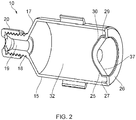
- the charge 10 comprises a generally cylindrical bottle-like container 15.
- the container includes a generally cylindrical body 16. At one end of the body an inclined wall 17 extends radially inwards. At the centre of the wall 17 a neck 18 is provided and has a central passage 19. In this embodiment a separate screw threaded collar 20 is provided for receiving a detonator and can be screwed onto the neck 18.
- the other end of the body 16 is closed by a partition/barrier/barrier membrane 25.
- the membrane 25 has an annular flange 26 that fits onto the open end of the body.
- a short annular skirt 27 depends from the flange. The skirt 27 is positioned to fit into the interior of the body.
- a longitudinal annular leg 29 extends and is closed by a concave plate 30 (so the plate 30 is "inside" the body).
- the interior of the body provides an enclosure 32 for receiving liquid explosive, such as nitromethane.
- a projectile in the form of a metal cone 37 (such as magnesium, aluminium or copper) is provided.
- the shape/profile of the cone 37 is complimentary with the shape of the plate/leg.
- the charge diameter is greater than the projectile diameter.
- the container could be formed from a plastics material.
- the cone could be formed as a thin plastic membrane.
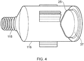
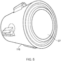
- FIG. 4 A further example of a charge of the type described in relation to Figures 1 to 3 is shown in Figures 4 to 6 .
- the charge I 10 is shown assembled in Figure 6 .
- the body 116 can be filled with liquid explosive and the collar 120 is screwed onto the body 116.
- a detonator 140 is fitted into the collar and a projectile 137 is fitted into the membrane 125.
- activation of the detonator 140 causes detonation of the liquid explosive material, which in turn causes projection of the projectile 137.
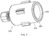
- FIGS 7 to 9 show a charge 210 formed according to a further embodiment.
- the charge 210 has a cylindrical container 215 with a screw threaded neck 218 at one end of its body 216.
- the other end of the body 216 is closed by a double cone arrangement.
- First and second cone members 250, 255 are placed, axially spaced from each other, into the interior of the body.
- cone members 250, 255 are provided in a nested format, with the second cone member nested inside the first cone member (with the cone apices being axially mutually spaced from each other).
- a liquid explosive material compartment 232 is formed between the first cone member and the neck.
- a liquid projectile material compartment 233 is formed between the two cones members.
- either/both of the cone members are welded/adhered or otherwise permanently fixed into the body.
- the container could be formed from a plastics material.
- the cones could be formed as thin plastic membranes.
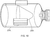
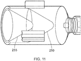
- FIG. 10 A further example of a charge 210 of the type described in relation to Figures 7 to 9 is shown in Figures 10 and 11 .
- Figure 10 shows the body with the collar screwed on.
- Figure 11 the cone member has been inserted.
- the body can be filled, for example, with liquid explosive and water.
- a detonator can be fitted into the collar.
- activation of the detonator causes detonation of the liquid explosive material, which in turn causes the water to be projected.
- the liquid explosive may be binary e.g. a sensitizer could be added first and then liquid explosive material.
- the first cone (defining the explosive material compartment/chamber) could be formed as part of the container, or could be provided separately and pre-fitted or fitted at the time of use.
- the second cone could be fitted/secured after filling with projectile material.
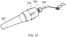
- Figures 12 and 13 show the charge 210 forming part of an underwater-compatible variation.
- An underwater housing 260 is provided and fits over/onto the end of the assembled charge.
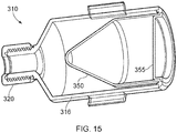
- Figures 14 and 15 show a charge 310 formed according to a further embodiment.
- the charge 310 is similar to the charge 210, having a liquid explosive material compartment 332 and a liquid projectile material compartment 333.
- a front membrane 355 has a generally flat profile and an inner cone 350 is provided with a (approximately) 60 degree angle.
- the figures show different variants formed in accordance with the present invention.
- the interlayer/liner/membrane between the explosive and the projectile whether that be a liquid projectile (e.g. water) or a metal (e.g. magnesium) liner.
- Some embodiments therefore allow the production of charges that do not have the projectile in and/or don't have explosive material in; they can be added at an appropriate time. Transport/storage of an empty or partially empty (and not fully enabled) charge container is therefore much safer.
- any sort of projectile could be used/fitted, for example a composite or single material projectile.
Landscapes
- Engineering & Computer Science (AREA)
- General Engineering & Computer Science (AREA)
- Manufacturing & Machinery (AREA)
- Chemical & Material Sciences (AREA)
- Combustion & Propulsion (AREA)
- Details Of Rigid Or Semi-Rigid Containers (AREA)
- Portable Nailing Machines And Staplers (AREA)
- Shaping Metal By Deep-Drawing, Or The Like (AREA)
- Filling Or Discharging Of Gas Storage Vessels (AREA)
- Toys (AREA)
Priority Applications (1)
| Application Number | Priority Date | Filing Date | Title |
|---|---|---|---|
| EP25189750.0A EP4624862A3 (fr) | 2019-05-25 | 2020-04-09 | Améliorations apportées ou se rapportant à des charges explosives |
Applications Claiming Priority (1)
| Application Number | Priority Date | Filing Date | Title |
|---|---|---|---|
| GB1907438.4A GB2582670B8 (en) | 2019-05-25 | 2019-05-25 | Improvements in or relating to explosive charges |
Related Child Applications (2)
| Application Number | Title | Priority Date | Filing Date |
|---|---|---|---|
| EP25189750.0A Division EP4624862A3 (fr) | 2019-05-25 | 2020-04-09 | Améliorations apportées ou se rapportant à des charges explosives |
| EP25189750.0A Division-Into EP4624862A3 (fr) | 2019-05-25 | 2020-04-09 | Améliorations apportées ou se rapportant à des charges explosives |
Publications (3)
| Publication Number | Publication Date |
|---|---|
| EP3745078A1 true EP3745078A1 (fr) | 2020-12-02 |
| EP3745078C0 EP3745078C0 (fr) | 2025-10-08 |
| EP3745078B1 EP3745078B1 (fr) | 2025-10-08 |
Family
ID=67385411
Family Applications (3)
| Application Number | Title | Priority Date | Filing Date |
|---|---|---|---|
| EP25189750.0A Pending EP4624862A3 (fr) | 2019-05-25 | 2020-04-09 | Améliorations apportées ou se rapportant à des charges explosives |
| EP20168891.8A Active EP3745078B1 (fr) | 2019-05-25 | 2020-04-09 | Améliorations apportées ou se rapportant à des charges explosives |
| EP20723779.3A Active EP3977042B1 (fr) | 2019-05-25 | 2020-05-07 | Charge creuse |
Family Applications Before (1)
| Application Number | Title | Priority Date | Filing Date |
|---|---|---|---|
| EP25189750.0A Pending EP4624862A3 (fr) | 2019-05-25 | 2020-04-09 | Améliorations apportées ou se rapportant à des charges explosives |
Family Applications After (1)
| Application Number | Title | Priority Date | Filing Date |
|---|---|---|---|
| EP20723779.3A Active EP3977042B1 (fr) | 2019-05-25 | 2020-05-07 | Charge creuse |
Country Status (4)
| Country | Link |
|---|---|
| US (1) | US20220325991A1 (fr) |
| EP (3) | EP4624862A3 (fr) |
| GB (2) | GB2582670B8 (fr) |
| WO (1) | WO2020239383A1 (fr) |
Families Citing this family (3)
| Publication number | Priority date | Publication date | Assignee | Title |
|---|---|---|---|---|
| GB202017072D0 (en) * | 2020-10-27 | 2020-12-09 | Uxo Control B V | Unexploded ordinance disposal method and system |
| CN116625175B (zh) * | 2023-07-25 | 2023-09-19 | 吉林市双林射孔器材有限责任公司 | 一种大孔径增压射孔弹 |
| GB202405504D0 (en) * | 2024-04-19 | 2024-06-05 | Alford Ip Ltd | Improvements in or relating to explosive charges |
Citations (3)
| Publication number | Priority date | Publication date | Assignee | Title |
|---|---|---|---|---|
| DE2745744A1 (de) * | 1976-11-29 | 1978-06-01 | Ici Ltd | Hohlsprengladungseinrichtung, gehaeuse und verfahren fuer den unterwassergebrauch |
| GB2209819A (en) * | 1987-09-15 | 1989-05-24 | Alford Sidney C | Shaping apparatus for an explosive charge |
| WO2003058155A1 (fr) * | 2002-01-08 | 2003-07-17 | Alford Sidney C | Dispositif disruptif pour engins explosifs |
Family Cites Families (28)
| Publication number | Priority date | Publication date | Assignee | Title |
|---|---|---|---|---|
| BE471713A (fr) * | 1946-03-09 | |||
| US2974595A (en) * | 1947-09-11 | 1961-03-14 | Welex Inc | Projectile |
| DE1946991C3 (de) * | 1969-09-17 | 1978-05-24 | Messerschmitt-Boelkow-Blohm Gmbh, 8000 Muenchen | Hohlladung |
| GB1475754A (en) * | 1974-10-21 | 1977-06-10 | Ici Ltd | Shaped charge device |
| GB1520692A (en) * | 1976-03-01 | 1978-08-09 | Ici Ltd | Shaped explosive charge casing |
| FR2429990B1 (fr) * | 1978-06-27 | 1985-11-15 | Saint Louis Inst | Charge explosive plate |
| GB2105015B (en) * | 1981-07-17 | 1985-08-21 | Alford Sidney C | Directed explosive cutting charge and method |
| DE8132666U1 (de) * | 1981-11-07 | 1984-01-31 | Rheinmetall GmbH, 4000 Düsseldorf | Einlage für eine Sprengladung zum Bilden eines im wesentlichen stabförmigen Projektils |
| US4714022A (en) * | 1984-09-05 | 1987-12-22 | Etat Francais | Warhead with tandem shaped charges |
| DE3506225A1 (de) * | 1985-02-22 | 1986-08-28 | Diehl GmbH & Co, 8500 Nürnberg | Gefechtskopfanordnung |
| DE3508740A1 (de) * | 1985-03-12 | 1986-10-16 | Karl 8898 Schrobenhausen Rudolf | Hohlladung zum einsatz gegen beton- und/oder gesteinsarmierte ziele |
| US4766813A (en) * | 1986-12-29 | 1988-08-30 | Olin Corporation | Metal shaped charge liner with isotropic coating |
| DE3705381A1 (de) * | 1987-02-20 | 1988-09-01 | Diehl Gmbh & Co | Sprengladung mit einer projektilbildenden metallischen einlage |
| AU8138791A (en) * | 1990-07-27 | 1992-01-30 | Dyno Wesfarmers Limited | Improvements in or relating to shaped charges |
| US5098487A (en) * | 1990-11-28 | 1992-03-24 | Olin Corporation | Copper alloys for shaped charge liners |
| US5155296A (en) * | 1992-03-18 | 1992-10-13 | The United States Of America As Represented By The Secretary Of The Army | Thermally enhanced warhead |
| US5522319A (en) * | 1994-07-05 | 1996-06-04 | The United States Of America As Represented By The United States Department Of Energy | Free form hemispherical shaped charge |
| FR2741142B1 (fr) * | 1995-11-13 | 1998-01-02 | Giat Ind Sa | Charge generatrice de noyau ayant une tenue a l'acceleration amelioree |
| US8375859B2 (en) * | 2010-03-24 | 2013-02-19 | Southwest Research Institute | Shaped explosive charge |
| US8434411B2 (en) * | 2011-01-19 | 2013-05-07 | Raytheon Company | Cluster explosively-formed penetrator warheads |
| US8616130B2 (en) * | 2011-01-19 | 2013-12-31 | Raytheon Company | Liners for warheads and warheads having improved liners |
| US9157705B1 (en) * | 2013-05-30 | 2015-10-13 | The United States Of America As Represented By The Secretary Of The Army | Projector for defeating buried mines |
| GB2522413B (en) * | 2014-01-22 | 2017-04-19 | Alford Res Ltd | Improvements in or relating to shaped charges |
| US10274292B1 (en) * | 2015-02-17 | 2019-04-30 | U.S. Department Of Energy | Alloys for shaped charge liners method for making alloys for shaped charge liners |
| FR3040481B1 (fr) * | 2015-08-31 | 2017-08-11 | Nexter Munitions | Tete militaire et systeme de defense modulaire mettant en oeuvre une telle tete militaire |
| RU2658734C2 (ru) * | 2016-07-05 | 2018-06-22 | Виктор Николаевич Лаврентьев | Удлинённый кумулятивный заряд |
| US10753183B2 (en) * | 2016-10-13 | 2020-08-25 | Geodynamics, Inc. | Refracturing in a multistring casing with constant entrance hole perforating gun system and method |
| AU2018288316A1 (en) * | 2017-06-23 | 2020-01-16 | DynaEnergetics Europe GmbH | Shaped charge liner, method of making same, and shaped charge incorporating same |
-
2019
- 2019-05-25 GB GB1907438.4A patent/GB2582670B8/en active Active
-
2020
- 2020-03-02 GB GB2002939.3A patent/GB2584361B/en active Active
- 2020-04-09 EP EP25189750.0A patent/EP4624862A3/fr active Pending
- 2020-04-09 EP EP20168891.8A patent/EP3745078B1/fr active Active
- 2020-05-07 WO PCT/EP2020/062689 patent/WO2020239383A1/fr not_active Ceased
- 2020-05-07 US US17/613,930 patent/US20220325991A1/en active Pending
- 2020-05-07 EP EP20723779.3A patent/EP3977042B1/fr active Active
Patent Citations (3)
| Publication number | Priority date | Publication date | Assignee | Title |
|---|---|---|---|---|
| DE2745744A1 (de) * | 1976-11-29 | 1978-06-01 | Ici Ltd | Hohlsprengladungseinrichtung, gehaeuse und verfahren fuer den unterwassergebrauch |
| GB2209819A (en) * | 1987-09-15 | 1989-05-24 | Alford Sidney C | Shaping apparatus for an explosive charge |
| WO2003058155A1 (fr) * | 2002-01-08 | 2003-07-17 | Alford Sidney C | Dispositif disruptif pour engins explosifs |
Also Published As
| Publication number | Publication date |
|---|---|
| EP3977042B1 (fr) | 2024-10-16 |
| EP3977042A1 (fr) | 2022-04-06 |
| GB201907438D0 (en) | 2019-07-10 |
| WO2020239383A1 (fr) | 2020-12-03 |
| EP4624862A2 (fr) | 2025-10-01 |
| GB202002939D0 (en) | 2020-04-15 |
| EP3977042C0 (fr) | 2024-10-16 |
| GB2582670B8 (en) | 2023-10-25 |
| EP3745078C0 (fr) | 2025-10-08 |
| US20220325991A1 (en) | 2022-10-13 |
| GB2584361A (en) | 2020-12-02 |
| GB2582670A (en) | 2020-09-30 |
| EP3745078B1 (fr) | 2025-10-08 |
| GB2582670B (en) | 2023-07-12 |
| GB2584361B (en) | 2023-02-01 |
| GB2582670A8 (en) | 2023-10-25 |
| EP4624862A3 (fr) | 2025-12-03 |
Similar Documents
| Publication | Publication Date | Title |
|---|---|---|
| EP3745078B1 (fr) | Améliorations apportées ou se rapportant à des charges explosives | |
| US3837527A (en) | Reinforced aerosol container | |
| US3298554A (en) | Insulated picnic jug or container | |
| US4015526A (en) | Explosive charge | |
| JP2012192210A5 (fr) | ||
| USD904006S1 (en) | Reusable bottle | |
| WO1991014148A1 (fr) | Projectile cassable non meurtrier | |
| EP0308054B1 (fr) | Formage par explosion de tuyaux métalliques | |
| CN111776490A (zh) | 定量取用机构 | |
| US7992498B2 (en) | Reduced collateral damage bomb (RCDB) and system and method of making same | |
| CN212424009U (zh) | 容器、定量取用机构及具有定量取用机构的粉料存储装置 | |
| US2644616A (en) | Saltcellar | |
| CA2514708A1 (fr) | Cone de charge a double anneau forme par explosion | |
| WO2017065695A4 (fr) | Couvercle avec récipient permettant le scellage multiple de bouteilles en matière plastique, de bouteilles en verres et d'autres récipients | |
| US20220212854A1 (en) | Container | |
| US9557150B2 (en) | Grenade round | |
| PL179040B3 (en) | Flexible membrane assembly for aerosol dispensers | |
| RU2371366C1 (ru) | Тара для двух несмешиваемых компонентов | |
| CA2730824A1 (fr) | Amorce comportant une charge reduite | |
| RU2021116922A (ru) | Диспенсеры для порошков и способы выдачи порошка | |
| JP3199132U (ja) | 携帯用物入れ | |
| US359212A (en) | William a | |
| RU2588452C2 (ru) | Аэрозольный баллончик | |
| US665334A (en) | Closing-cap for vessels. | |
| SU1431862A1 (ru) | Устройство дл отделени деталей от смеси сыпучих материалов |
Legal Events
| Date | Code | Title | Description |
|---|---|---|---|
| PUAI | Public reference made under article 153(3) epc to a published international application that has entered the european phase |
Free format text: ORIGINAL CODE: 0009012 |
|
| STAA | Information on the status of an ep patent application or granted ep patent |
Free format text: STATUS: THE APPLICATION HAS BEEN PUBLISHED |
|
| AK | Designated contracting states |
Kind code of ref document: A1 Designated state(s): AL AT BE BG CH CY CZ DE DK EE ES FI FR GB GR HR HU IE IS IT LI LT LU LV MC MK MT NL NO PL PT RO RS SE SI SK SM TR |
|
| AX | Request for extension of the european patent |
Extension state: BA ME |
|
| RIN1 | Information on inventor provided before grant (corrected) |
Inventor name: ALFORD, ROLAND Inventor name: ALFORD, SIDNEY |
|
| STAA | Information on the status of an ep patent application or granted ep patent |
Free format text: STATUS: REQUEST FOR EXAMINATION WAS MADE |
|
| 17P | Request for examination filed |
Effective date: 20210601 |
|
| RBV | Designated contracting states (corrected) |
Designated state(s): AL AT BE BG CH CY CZ DE DK EE ES FI FR GB GR HR HU IE IS IT LI LT LU LV MC MK MT NL NO PL PT RO RS SE SI SK SM TR |
|
| STAA | Information on the status of an ep patent application or granted ep patent |
Free format text: STATUS: EXAMINATION IS IN PROGRESS |
|
| 17Q | First examination report despatched |
Effective date: 20230103 |
|
| GRAP | Despatch of communication of intention to grant a patent |
Free format text: ORIGINAL CODE: EPIDOSNIGR1 |
|
| STAA | Information on the status of an ep patent application or granted ep patent |
Free format text: STATUS: GRANT OF PATENT IS INTENDED |
|
| INTG | Intention to grant announced |
Effective date: 20250725 |
|
| GRAS | Grant fee paid |
Free format text: ORIGINAL CODE: EPIDOSNIGR3 |
|
| GRAA | (expected) grant |
Free format text: ORIGINAL CODE: 0009210 |
|
| STAA | Information on the status of an ep patent application or granted ep patent |
Free format text: STATUS: THE PATENT HAS BEEN GRANTED |
|
| AK | Designated contracting states |
Kind code of ref document: B1 Designated state(s): AL AT BE BG CH CY CZ DE DK EE ES FI FR GB GR HR HU IE IS IT LI LT LU LV MC MK MT NL NO PL PT RO RS SE SI SK SM TR |
|
| REG | Reference to a national code |
Ref country code: GB Ref legal event code: FG4D Ref country code: CH Ref legal event code: F10 Free format text: ST27 STATUS EVENT CODE: U-0-0-F10-F00 (AS PROVIDED BY THE NATIONAL OFFICE) Effective date: 20251008 |
|
| REG | Reference to a national code |
Ref country code: DE Ref legal event code: R096 Ref document number: 602020060011 Country of ref document: DE |
|
| REG | Reference to a national code |
Ref country code: IE Ref legal event code: FG4D |
|
| U01 | Request for unitary effect filed |
Effective date: 20251105 |
|
| U07 | Unitary effect registered |
Designated state(s): AT BE BG DE DK EE FI FR IT LT LU LV MT NL PT RO SE SI Effective date: 20251112 |
|
| PGFP | Annual fee paid to national office [announced via postgrant information from national office to epo] |
Ref country code: GB Payment date: 20260325 Year of fee payment: 7 |
|
| PG25 | Lapsed in a contracting state [announced via postgrant information from national office to epo] |
Ref country code: ES Free format text: LAPSE BECAUSE OF FAILURE TO SUBMIT A TRANSLATION OF THE DESCRIPTION OR TO PAY THE FEE WITHIN THE PRESCRIBED TIME-LIMIT Effective date: 20251008 |
|
| PG25 | Lapsed in a contracting state [announced via postgrant information from national office to epo] |
Ref country code: NO Free format text: LAPSE BECAUSE OF FAILURE TO SUBMIT A TRANSLATION OF THE DESCRIPTION OR TO PAY THE FEE WITHIN THE PRESCRIBED TIME-LIMIT Effective date: 20260108 |
|
| PG25 | Lapsed in a contracting state [announced via postgrant information from national office to epo] |
Ref country code: HR Free format text: LAPSE BECAUSE OF FAILURE TO SUBMIT A TRANSLATION OF THE DESCRIPTION OR TO PAY THE FEE WITHIN THE PRESCRIBED TIME-LIMIT Effective date: 20251008 |
|
| PG25 | Lapsed in a contracting state [announced via postgrant information from national office to epo] |
Ref country code: RS Free format text: LAPSE BECAUSE OF FAILURE TO SUBMIT A TRANSLATION OF THE DESCRIPTION OR TO PAY THE FEE WITHIN THE PRESCRIBED TIME-LIMIT Effective date: 20260108 |
|
| PG25 | Lapsed in a contracting state [announced via postgrant information from national office to epo] |
Ref country code: IS Free format text: LAPSE BECAUSE OF FAILURE TO SUBMIT A TRANSLATION OF THE DESCRIPTION OR TO PAY THE FEE WITHIN THE PRESCRIBED TIME-LIMIT Effective date: 20260208 |
|
| PG25 | Lapsed in a contracting state [announced via postgrant information from national office to epo] |
Ref country code: PL Free format text: LAPSE BECAUSE OF FAILURE TO SUBMIT A TRANSLATION OF THE DESCRIPTION OR TO PAY THE FEE WITHIN THE PRESCRIBED TIME-LIMIT Effective date: 20251008 |