EP3745221A1 - Steuerungsvorrichtung, steuerungsverfahren und steuerungsprogramm - Google Patents
Steuerungsvorrichtung, steuerungsverfahren und steuerungsprogramm Download PDFInfo
- Publication number
- EP3745221A1 EP3745221A1 EP18901114.1A EP18901114A EP3745221A1 EP 3745221 A1 EP3745221 A1 EP 3745221A1 EP 18901114 A EP18901114 A EP 18901114A EP 3745221 A1 EP3745221 A1 EP 3745221A1
- Authority
- EP
- European Patent Office
- Prior art keywords
- filtering condition
- communication data
- communication
- input
- drive device
- Prior art date
- Legal status (The legal status is an assumption and is not a legal conclusion. Google has not performed a legal analysis and makes no representation as to the accuracy of the status listed.)
- Withdrawn
Links
Images




Classifications
-
- G—PHYSICS
- G05—CONTROLLING; REGULATING
- G05B—CONTROL OR REGULATING SYSTEMS IN GENERAL; FUNCTIONAL ELEMENTS OF SUCH SYSTEMS; MONITORING OR TESTING ARRANGEMENTS FOR SUCH SYSTEMS OR ELEMENTS
- G05B19/00—Program-control systems
- G05B19/02—Program-control systems electric
- G05B19/18—Numerical control [NC], i.e. automatically operating machines, in particular machine tools, e.g. in a manufacturing environment, so as to execute positioning, movement or co-ordinated operations by means of program data in numerical form
- G05B19/4155—Numerical control [NC], i.e. automatically operating machines, in particular machine tools, e.g. in a manufacturing environment, so as to execute positioning, movement or co-ordinated operations by means of program data in numerical form characterised by program execution, i.e. part program or machine function execution, e.g. selection of a program
-
- G—PHYSICS
- G05—CONTROLLING; REGULATING
- G05B—CONTROL OR REGULATING SYSTEMS IN GENERAL; FUNCTIONAL ELEMENTS OF SUCH SYSTEMS; MONITORING OR TESTING ARRANGEMENTS FOR SUCH SYSTEMS OR ELEMENTS
- G05B19/00—Program-control systems
- G05B19/02—Program-control systems electric
- G05B19/04—Program control other than numerical control, i.e. in sequence controllers or logic controllers
- G05B19/05—Programmable logic controllers, e.g. simulating logic interconnections of signals according to ladder diagrams or function charts
- G05B19/054—Input/output
-
- G—PHYSICS
- G06—COMPUTING OR CALCULATING; COUNTING
- G06F—ELECTRIC DIGITAL DATA PROCESSING
- G06F21/00—Security arrangements for protecting computers, components thereof, programs or data against unauthorised activity
- G06F21/50—Monitoring users, programs or devices to maintain the integrity of platforms, e.g. of processors, firmware or operating systems
- G06F21/55—Detecting local intrusion or implementing counter-measures
- G06F21/552—Detecting local intrusion or implementing counter-measures involving long-term monitoring or reporting
-
- G—PHYSICS
- G06—COMPUTING OR CALCULATING; COUNTING
- G06F—ELECTRIC DIGITAL DATA PROCESSING
- G06F21/00—Security arrangements for protecting computers, components thereof, programs or data against unauthorised activity
- G06F21/70—Protecting specific internal or peripheral components, in which the protection of a component leads to protection of the entire computer
- G06F21/82—Protecting input, output or interconnection devices
- G06F21/85—Protecting input, output or interconnection devices interconnection devices, e.g. bus-connected or in-line devices
-
- H—ELECTRICITY
- H04—ELECTRIC COMMUNICATION TECHNIQUE
- H04L—TRANSMISSION OF DIGITAL INFORMATION, e.g. TELEGRAPHIC COMMUNICATION
- H04L43/00—Arrangements for monitoring or testing data switching networks
- H04L43/02—Capturing of monitoring data
- H04L43/028—Capturing of monitoring data by filtering
-
- H—ELECTRICITY
- H04—ELECTRIC COMMUNICATION TECHNIQUE
- H04L—TRANSMISSION OF DIGITAL INFORMATION, e.g. TELEGRAPHIC COMMUNICATION
- H04L63/00—Network architectures or network communication protocols for network security
- H04L63/02—Network architectures or network communication protocols for network security for separating internal from external traffic, e.g. firewalls
- H04L63/0227—Filtering policies
-
- H—ELECTRICITY
- H04—ELECTRIC COMMUNICATION TECHNIQUE
- H04L—TRANSMISSION OF DIGITAL INFORMATION, e.g. TELEGRAPHIC COMMUNICATION
- H04L63/00—Network architectures or network communication protocols for network security
- H04L63/14—Network architectures or network communication protocols for network security for detecting or protecting against malicious traffic
- H04L63/1408—Network architectures or network communication protocols for network security for detecting or protecting against malicious traffic by monitoring network traffic
-
- H—ELECTRICITY
- H04—ELECTRIC COMMUNICATION TECHNIQUE
- H04L—TRANSMISSION OF DIGITAL INFORMATION, e.g. TELEGRAPHIC COMMUNICATION
- H04L67/00—Network arrangements or protocols for supporting network services or applications
- H04L67/14—Session management
- H04L67/141—Setup of application sessions
-
- G—PHYSICS
- G05—CONTROLLING; REGULATING
- G05B—CONTROL OR REGULATING SYSTEMS IN GENERAL; FUNCTIONAL ELEMENTS OF SUCH SYSTEMS; MONITORING OR TESTING ARRANGEMENTS FOR SUCH SYSTEMS OR ELEMENTS
- G05B2219/00—Program-control systems
- G05B2219/30—Nc systems
- G05B2219/31—From computer integrated manufacturing till monitoring
- G05B2219/31347—Communication adaptors between network and each machine
-
- Y—GENERAL TAGGING OF NEW TECHNOLOGICAL DEVELOPMENTS; GENERAL TAGGING OF CROSS-SECTIONAL TECHNOLOGIES SPANNING OVER SEVERAL SECTIONS OF THE IPC; TECHNICAL SUBJECTS COVERED BY FORMER USPC CROSS-REFERENCE ART COLLECTIONS [XRACs] AND DIGESTS
- Y02—TECHNOLOGIES OR APPLICATIONS FOR MITIGATION OR ADAPTATION AGAINST CLIMATE CHANGE
- Y02P—CLIMATE CHANGE MITIGATION TECHNOLOGIES IN THE PRODUCTION OR PROCESSING OF GOODS
- Y02P90/00—Enabling technologies with a potential contribution to greenhouse gas [GHG] emissions mitigation
- Y02P90/02—Total factory control, e.g. smart factories, flexible manufacturing systems [FMS] or integrated manufacturing systems [IMS]
Definitions
- the present disclosure relates to a technique for filtering communication data by a control device.
- controllers In various production sites, industrial control devices (hereinafter also referred to as “controllers”) have been introduced, such as programmable logic controllers (PLCs) and robot controllers. Such controllers can control various industrial drive devices, thus automating the production process.
- PLCs programmable logic controllers
- robot controllers Such controllers can control various industrial drive devices, thus automating the production process.
- Such a controller serves as a gateway and manages the exchange of communication data between a higher-level network and a lower-level network.
- Japanese Patent Laying-Open No. 2017-199154 discloses an equipment system which allows mutual connection of different networks and also allows easy setting for mutual control of various processing machines connected to the different networks.
- the controller allows passage of only the communication data that satisfies a set filtering condition.
- the communication data that should be allowed to pass changes depending on the situation. Accordingly, it is desired that the filtering condition be changed appropriately depending on the situation.
- Example methods for changing the filtering condition for communication data include changing a network setting after stopping the drive devices in a factory automation (FA) system. Stopping the drive devices in an FA system, however, would result in a great opportunity loss. Thus, it is desired that a stop of FA system be avoided as much as possible when the filtering condition is changed.
- FA factory automation
- An object of the present disclosure in one aspect is to provide a technique that can change a filtering condition for communication data without stopping a drive device.
- a control device that controls a drive device comprises: a physical first communication port that connects to a first network to which an information processing device belongs; a physical second communication port that connects to a second network to which the drive device belongs; and a storage device that stores a user program created for controlling the drive device.
- the user program includes a filtering function for switching a filtering condition in accordance with a setting for the filtering condition that is input during execution of the user program.
- the filtering condition is used for determining whether or not to transmit communication data received from one device to another device.
- the one device is one of the drive device and the information processing device, and the other device is the other of the drive device and the information processing device.
- the control device can change the filtering condition for communication data without stopping the drive device.
- the setting for the filtering condition that is input includes a setting for specifying whether or not to execute a process for changing the filtering condition.
- control device can adjust the timing of execution of the filtering condition arbitrarily during driving of the drive device.
- the setting for the filtering condition that is input includes a setting for specifying an operation mode of the filtering function when the filtering condition is satisfied.
- the operation mode includes a mode in which only the communication data received from the one device is transmitted to the other device, and a mode in which the communication data received from the one device is not transmitted to the other device.
- control device can switch the operation mode of the filtering function, even during driving of the drive device.
- the setting for the filtering condition that is input includes a setting for specifying whether transmission of the communication data received from the drive device is to be filtered, or the communication data received from the information processing device is to be filtered.
- control device can appropriately switch the communication direction of the communication data to be filtered, even during driving of the drive device.
- the setting for the filtering condition that is input includes a setting for specifying a communication protocol for the communication data to be filtered.
- control device can switch the communication protocol for an object of filtering, even during driving of the drive device.
- the setting for the filtering condition that is input includes at least one of a setting for specifying a destination of the communication data received from the one device, and a setting for specifying a source of the communication data received from the one device.
- control device can appropriately switch the source device or destination device to be filtered, even during driving of the drive device.
- a control method for a control device that controls a drive device comprises: establishing communication with an information processing device that belongs to a first network; establishing communication with the drive device that belongs to a second network; executing, by the control device, a user program created for controlling the drive device; and switching, by the user program, a filtering condition in accordance with a setting for the filtering condition that is input during execution of the user program, the filtering condition being used for determining whether or not to transmit communication data received from one device to another device, the one device being one of the drive device and the information processing device, the other device being the other of the drive device and the information processing device.
- the control device can change the filtering condition for communication data without stopping the drive device.
- a control program for a control device that controls a drive device causes the control device to execute: establishing communication with an information processing device that belongs to a first network; establishing communication with the drive device that belongs to a second network; executing a user program created for controlling the drive device; and switching a filtering condition in accordance with a setting for the filtering condition that is input during execution of the user program, the filtering condition being used for determining whether or not to transmit communication data received from one device to another device, the one device being one of the drive device and the information processing device, the other device being the other of the drive device and the information processing device.
- the control device can change the filtering condition for communication data without stopping the drive device.
- the filtering condition for communication data can be changed without stopping a drive device.
- FIG. 1 is a diagram showing a configuration example of FA system 1.
- FA system 1 is a system for controlling an object of control, such as an apparatus and equipment, and automating the production process.
- FA system 1 includes one or more controllers 100, one or more information processing devices 200, and one or more drive devices 300.
- Controller 100 includes physical communication ports 100P1, 100P2 and a storage device 108.
- Controller 100 is connectable to a plurality of networks.
- communication port 100P1 (first communication port) is connected to a network N1 (first network)
- communication port 100P2 (second communication port) is connected to a network N2 (second network).
- EtherNET registered trademark
- network N1 is not limited to EtherNET, and any communication means can be employed.
- information processing device 200 is connected to network N1.
- Examples of information processing device 200 include a personal computer (PC), a tablet terminal, a smartphone, and a display (e.g., a human machine interface (HMI)).
- PC personal computer
- HMI human machine interface
- Network N2 is a lower-level network than network N1.
- EtherNet/IP registered trademark
- drive device 300 is connected to network N2.
- Drive device 300 includes various industrial devices for automating the production process.
- drive device 300 includes an arm robot, a robot controller for controlling the arm robot, an image sensor for imaging a workpiece conveyed during the production process, and other devices used in the production process.
- Storage device 108 stores a user program 110.
- User program 110 is a control program implemented by a designer for drive device 300.
- a development tool for user program 110 is installed in information processing device 200, which is, for example, a PC.
- a designer can design user program 110 tailored to the configuration of drive device 300 by combining a plurality of types of predefined instructions on the development tool.
- the instructions that can be combined on the development tool include a control instruction for drive device 300 and a filtering instruction for communication data.
- User program 110 compiled on the development tool is installed in controller 100.
- user program 110 includes a control function 150 for drive device 300 and a filtering function 152 for communication data.
- control function 150 includes control function 150 and filtering function 152.
- Each of control function 150 and filtering function 152 is typically a program.
- Control function 150 outputs a control instruction to drive device 300 in accordance with the defined details of control.
- Filtering function 152 switches the filtering condition in accordance with the setting for filtering condition that is input during execution of user program 110, the filtering condition being used for determining whether or not to transmit communication data received from one device to the other device.
- the one device is one of information processing device 200 and drive device 300
- the other device is the other of information processing device 200 and drive device 300.
- one of information processing device 200 and drive device 300 that serves as a source of communication data is also referred to as a "source device”.
- One of information processing device 200 and drive device 300 that serves as a destination of communication data is also referred to as a "destination device”.
- controller 100 can change the filtering condition for communication data without stopping drive device 300. Thus, controller 100 can appropriately switch the communication data to be filtered in accordance with the status of FA system 1.
- the communication data to be filtered by filtering function 152 may be any type of data that is transmitted between different networks N1, N2.
- the communication data to be filtered may be communication packets conforming to a communication protocol, such as TCP/IP, or may be frames transmitted over field networks.
- the filtering condition that can be set for filtering function 152 may be a single condition, or may be a plurality of conditions.
- Fig. 2 is a schematic diagram showing a schematic configuration of FA system 1 according to the present embodiment.
- FA system 1 includes one or more controllers 100, one or more information processing devices 200, and one or more drive devices 300.
- Controller 100 is connectable to a plurality of networks.
- controller 100 is connected to higher-level network N1 and lower-level network N2.
- Higher-level network N1 includes information processing device 200 connected thereto.
- Information processing device 200 is a communication device connectable to network N1.
- information processing device 200 is constituted of at least one of: one or more support devices 200A, one or more server devices 200B, and one or more displays 200C.
- Support device 200A provides a designer with a development environment for designing user program 110.
- Support device 200A is, for example, a notebook PC, a desktop PC, a tablet terminal, a smartphone, or the like.
- a designer can design user program 110 on support device 200A and download user program 110 to controller 100 via network N1.
- Server device 200B may be a database system, a manufacturing execution system (MES), or the like.
- the manufacturing execution system acquires information from a manufacturing apparatus or equipment to be controlled, thus monitoring and managing the whole production.
- the manufacturing execution system can handle order information, quality information, shipment information, or the like. This is, however, not a limitation.
- a device that provides an information-related service (a process for acquiring various types of information from an object of control and performing a macro or micro analysis) may be connected to network N1.
- the various types of information received by server device 200B from controller 100 can be an object to be filtered by filtering function 152 of controller 100 (see Fig. 1 ).
- Display 200C receives a manipulation from the user and outputs, to controller 100, a command corresponding to the user's manipulation.
- the command output from display 200C can be an object to be filtered by filtering function 152 of controller 100 (see Fig. 1 ).
- Display 200C graphically represents the result of calculation at controller 100.
- Lower-level network N2 includes drive device 300 connected thereto.
- Drive device 300 is a collection of devices for performing prescribed work on a workpiece W directly or indirectly.
- drive device 300 is constituted of remote IO devices 310, 320, an image sensor 315, and an arm robot 325.
- Remote IO device 310 has a plurality of physical communication ports. To the respective communication ports, different networks are connectable. In the example of Fig. 2 , remote IO device 310 has two communication ports 310P1, 310P2. Network N2 is divided by a hub 305, one of which is connected to communication port 310P1. Communication port 310P2 has connection to a network N3. Network N3 is preferably a field network which performs fixed-cycle communication ensuring the data arrival time. Known examples of such field networks which perform fixed-cycle communication include EtherCAT (registered trademark) and CompoNet (registered trademark).
- Remote IO device 310 controls image sensor 315 in accordance with a control command from controller 100.
- image sensor 315 sequentially images workpieces W transported on a conveyor, and executes predetermined image processing on the obtained images.
- image sensor 315 sequentially performs quality inspection of workpieces W transported on the conveyor.
- the results of inspection by image sensor 315 are sequentially sent to controller 100 via remote IO device 310.
- Remote IO device 320 has a plurality of physical communication ports. To the respective communication ports, different networks are connectable. In the example of Fig. 2 , remote IO device 320 has two communication ports 320P1, 320P2. Network N2 is divided by hub 305, one of which is connected to communication port 310P2. Communication port 320P2 has connection to a network N3. Network N3 is preferably a field network which performs fixed-cycle communication ensuring the data arrival time. Known examples of such field networks which perform fixed-cycle communication include EtherCAT and CompoNet.
- Remote IO device 320 controls arm robot 325 in accordance with a control command from controller 100.
- controller 100 outputs a control command to remote IO device 320 for causing arm robot 325 to perform prescribed work (working process B).
- remote IO device 320 controls arm robot 325.
- remote IO device 320 provides a control command to remove, from the conveyor, workpiece W condemned by the inspection. The status (e.g., the position and angle of each joint) of arm robot 325 is sequentially fed back from remote IO device 320 to controller 100.
- user program 110 includes filtering function 152 for switching a filtering condition in accordance with input of the setting for filtering condition, the filtering condition being used for determining whether or not to transmit communication data received from one device (i.e., source device) to the other device (i.e., destination device).
- the one device is one of information processing device 200 and drive device 300
- the other device is the other of information processing device 200 and drive device 300.
- Filtering function 152 is a program (control instruction) for filtering communication data that passes controller 100, and may be defined by any of various types of programs.
- filtering function 152 may be defined by a function block diagram (FBD).
- filtering function 152 may be defined by other program languages.
- filtering function 152 may be defined by any of a ladder diagram (LD), an instruction list (IL), a structured text (ST), and a sequential function chart (SFC); or a combination thereof.
- filtering function 152 may be defined by a general-purpose programming language, such as JavaScript (registered trademark) or C language.
- Fig. 3 is a diagram showing filtering function 152 defined by a function block FB.
- function block FB includes input parts 155A to 155F for receiving the setting of filtering condition, and output parts 157A to 157D for outputting the result of setting the filtering condition.
- Input parts 155A to 155F receive input of the setting for filtering condition of filtering function 152. That is, filtering function 152 switches the filtering condition in accordance with the values input to input parts 155A to 155F.
- Input part 155A illustrated as “Execute” receives a setting for specifying whether or not to execute a process for changing the filtering condition.
- input part 155A receives an input of "True” or “False”.
- filtering function 152 does not change the filtering condition.
- a process for changing the filtering condition is executed.
- the filtering conditions that are input to other input parts 155B to 155F are set as new filtering conditions.
- controller 100 can adjust the timing of execution of the filtering condition arbitrarily during driving of drive device 300.
- Input part 155B illustrated as “Action” receives a setting for specifying the operation mode of filtering function 152 when the filtering condition is satisfied.
- input part 155B receives an input of "pass” or "block”.
- filtering function 152 sets a filtering condition so that only the communication data that satisfies the filtering condition is allowed to pass. That is, in this case, only the communication data that satisfies the filtering condition is transmitted to the destination device, and other communication data is not transmitted to the destination device.
- filtering function 152 sets a filtering condition so that communication data that satisfies the filtering condition is blocked.
- controller 100 can switch the operation mode of filtering function 152 appropriately in accordance with the value input to input part 155B, even during driving of drive device 300.
- Input part 155C illustrated as "Direction" receives an input for specifying the communication direction of the communication data to be filtered. That is, input part 155C receives an input for specifying whether the transmission of communication data received from drive device 300 is to be filtered, or the communication data received from information processing device 200 is to be filtered. By way of example, input part 155C receives an input of "in” or “out”. When “in” is input to input part 155C, filtering function 152 changes the filtering condition so that communication data transmitted from information processing device 200, which belongs to higher-level network N1, to drive device 300, which belongs to lower-level network N2, is to be filtered.
- filtering function 152 changes the filtering condition so that communication data transmitted from drive device 300, which belongs to lower-level network N2, to information processing device 200, which belongs to higher-level network N1, is to be filtered.
- controller 100 can appropriately switch the communication direction of the communication data to be filtered, in accordance with the value input to input part 155C, even during driving of drive device 300.
- Input part 155D illustrated as "Protocol” receives an input for specifying the communication protocol for the communication data to be filtered.
- input part 155D receives an input of the identification information of the communication protocol.
- the identification information may be specified by the communication protocol name or communication protocol identification (ID).
- input part 155D receives an input of "TCP” or "FTP”.
- filtering function 152 changes the filtering condition so that communication data conforming to a TCP protocol is to be filtered.
- filtering function 152 changes the filtering condition so that communication data conforming to an FTP protocol is to be filtered.
- controller 100 can appropriately switch the communication protocol for an object of filtering, in accordance with the value input to input part 155D, even during driving of drive device 300.
- the communication protocol specified as an object of filtering at input part 155D may be specified for higher-level network N1 or for lower-level network N2.
- Input part 155E illustrated as "IP Address” receives an input for specifying the destination device.
- the destination device is specified by the IP address.
- filtering function 152 changes the filtering condition so that communication data to be sent to the destination device having an IP address of "10.0.0.1" is to be filtered.
- controller 100 can appropriately switch the source device to be filtered, in accordance with the value input to input part 155E, even during driving of drive device 300.
- the destination device of communication data can be specified at input part 155E.
- function block FB may instead be defined to specify the source device of communication data at input part 155E or other input parts.
- Input part 155F illustrated as "Port” receives an input for specifying the port number of the destination device of communication data.
- filtering function 152 changes the filtering condition so that communication data to be sent to the port number "80" of the destination device is to be filtered.
- controller 100 can appropriately switch the port number to be filtered, in accordance with the value input to input part 155F, even during driving of drive device 300.
- the communication port of the destination device of communication data can be specified at input part 155F.
- function block FB may instead be defined to specify the port number of the source device of communication data at input part 155F or other input parts.
- a signal indicating normal termination is output from output part 157A illustrated as "Done”.
- a signal indicating that the changing process is in progress is output from output part 157B illustrated as “Busy”.
- a signal indicating abnormal termination is output from output part 157C illustrated as "Error”.
- an error ID for identifying the details of the error is output from output part 157D illustrated as "ErrorID”.
- Function block FB may include various other input parts and output parts, in addition to input parts 155A to 155F and output parts 157A to 157D.
- function block FB may further include an input part for specifying a communication interface. While function block FB receives only one filtering condition in the above-described example, function block FB may instead be defined to receive a plurality of filtering conditions.
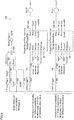
- FIG. 4 is a diagram showing an example user program including function block FB described in Fig. 3 .
- user program 110 is defined by a ladder program.
- User program 110 is defined so that the filtering condition for communication data is changed depending on the working process on a workpiece.
- User program 110 shown in Fig. 4 does not illustrate the whole process in controller 100. For example, a part of the logic at switching between working processes is omitted.
- User program 110 is defined by input elements IN0 to IN7, function blocks FB0 to FB2, and output elements OUTO to OUT2.
- Each of function blocks FB1, FB2 corresponds to function block FB having filtering function 152 described in Fig. 3 .
- each of input elements IN0 to IN7 is switched in accordance with the assigned variable.
- input element IN0 is assigned with a variable "ChangeTrigger".
- Input element IN1 is assigned with a variable "Busy0".
- the variable “BusyO” is a Boolean data type.
- the variable “BusyO” is associated with the output "Busy” of function block FB1. Accordingly, the value of input element IN1 is switched in accordance with the value of the output "Busy” of function block FB1.
- the value of the variable “BusyO” at input element IN1 is opposite to the value of the output "Busy” of function block FB1.
- Input element IN2 is assigned with a variable "Done0".
- the variable “DoneO” is associated with the output "Done” of function block FB1.
- Input element IN3 is assigned with a variable "Error0".
- the variable “Error0” is associated with the output "Error” of function block FB1.
- Input element IN4 is assigned with a variable "SettingTrigger0".
- Input element IN5 is assigned with a variable "PA".
- Input element IN6 is assigned with a variable "SettingTrigger1".
- a reset process for working process B is defined in user program 110, and the value of the variable “SettingTrigger1” is switched in accordance with the result of the reset process.
- Input element IN7 is assigned with a variable "PB".
- Function block FB0 is a program for executing the reset process which is executed at the start of working process A.
- Function block FB0 has input parts "Set", “Reset1", and an output part "Q1".
- Function block FB1 is a program for changing the filtering condition for communication data.
- function block FB1 executes the process for changing the filtering condition.
- function block FB1 sets, as a new filtering condition, the filtering condition according to "pass" input to the input part “Action”, “in” input to the input part “Direction”, “TCP” input to the input part “Protocol”, “10.0.0.1” input to the input part “IP Address”, and “80” input to the input part “Port”.
- the method for changing the filtering condition has already been described in detail in Fig. 3 , and thus the description thereof is not repeated.
- Function block FB2 is a program for changing the filtering condition for communication data.
- function block FB2 executes the process for changing the filtering condition.
- function block FB2 sets, as a new filtering condition, the filtering condition according to "pass" input to the input part “Action”, “in” input to the input part “Direction”, “FTP” input to the input part “Protocol”, “10.0.0.2” input to the input part “IP Address”, and “20” input to the input part “Port”.
- the method for changing the filtering condition has already been described in detail in Fig. 3 , and thus the description thereof is not repeated.
- each of output elements OUTO to OUT2 is switched in accordance with the output value of an associated function block.
- Output element OUTO is assigned with a variable "SettingTrigger0".
- Output element OUTO is also associated with the output "Q1" of function block FB0. As a result, the value of output element OUTO is switched in accordance with the value of the output "Q1".
- Output element OUT1 is assigned with a variable "Done0". Output element OUT1 is also associated with the output "Done” of function block FB1. As a result, the value of output element OUT1 is switched in accordance with the value of the output "Done” of function block FB1.
- Output element OUT2 is assigned with a variable "Done1". Output element OUT2 is also associated with the output "Done” of function block FB2. As a result, the value of output element OUT2 is switched in accordance with the value of the output "Done” of function block FB2.
- a filtering condition that is input to function block FB1 is set for working process A
- a filtering condition that is input to function block FB2 is set for working process B.
- the filtering condition if fixed, would have to be set such that communication data required to pass for working process A and communication data required to pass for working process B are both allowed to pass all the time.
- user program 110 shown in Fig. 4 eliminates the need for that.
- the filtering condition can be changed depending on the working process.
- user program 110 may be defined to change the filtering condition depending on other situations.
- user program 110 may be defined to, when the configuration of drive device 300 in FA system 1 has changed, set a filtering condition tailored to the configuration of FA system 1.
- controller 100 can block the communication device.
- a function block that monitors the network status may be used, for example. Such a function block regularly monitors the status of a network table and detects connection/disconnection of a communication device from the information on a change of the network table.
- user program 110 may be defined to, upon a malicious attack from an external device, set a filtering condition for preventing the malicious attack.
- a communication driver of controller 100 monitors the amount of reception data per unit time (e.g., the packet count received per unit time), and, when the amount of reception data exceeds a prescribed threshold value, determines the presence of a malicious attack from an external device.
- filtering function 152 blocks the external device that is delivering the malicious attack, based on the IP address, the port number, or other information.
- filtering function 152 may block the reception of all communication packets.
- user program 110 may be defined to, when the connection status of communication of controller 100 has changed, set a filtering condition tailored to the connection status.
- filtering function 152 allows passage of the reception data from a source device only during a period from the establishment of communication with the source device, to the disconnection. At other times, filtering function 152 blocks the reception data from the source device.
- filtering function 152 can allow passage of communication data only during a necessary period of time, thereby enhancing security.
- Controller 100 determines whether or not to filter communication data received from a source device, depending on whether or not the received communication data satisfies a filtering condition.
- the information for determining whether or not to filter communication data is defined in the communication data.
- the communication data includes at least one of: the identification information (e.g., IP address or MAC address) of the source device, the port number of the destination device, the communication protocol used when the communication data was received, the identification information (e.g., IP address or MAC address) of the destination device, the port number of the source device, and the communication protocol used when the communication data was transmitted.
- Controller 100 extracts such information from the communication data, and determines whether or not to filter the communication data, depending on whether or not the information matches the filtering condition.
- the communication data to be filtered by controller 100 may be any type of communication data that can be transmitted between different networks.
- the following describes an example of communication data to be filtered by controller 100 with reference to Fig. 5 .
- the communication data to be filtered by controller 100 includes, for example, a communication packet conforming to a TCP/IP protocol.
- Fig. 5 is a diagram showing the data structure of a communication packet conforming to a TCP/IP protocol.
- the source device divides the data to be transmitted into a plurality of communication packets and sequentially transmits the communication packets to controller 100.
- Fig. 5 shows a communication packet PA, which is one of the communication packets divided by the source device.
- Communication packet PA is constituted of an Ethernet header, which is a header part of the Ethenet protocol, and Ethernet data, which is a data part of the Ethenet protocol.
- the Ethernet data is constituted of an IP header, which is a header part of the IP protocol, and IP data, which is a data part of the IP protocol.
- the IP data is constituted of a TCP header, which is a header part of the TCP protocol, and TCP data, which is a data part of the TCP protocol.
- the IP header of communication packet PA includes the IP address of the source device, the IP address of the destination device, and the communication protocol.
- the TCP header of communication packet PA includes the port number of the source device and the port number of the destination device.
- the TCP data of communication packet PA includes the content of the data to be transmitted.
- the data to be transmitted includes, for example, various variables representing the status of drive device 300, and instructions of information processing device 200 to acquire various variables.
- the variables refer to the various variables contained in user program 110. The variables are changed depending on the statuses of various components of drive device 300.
- controller 100 In response to receiving communication packet PA, controller 100 extracts, from communication packet PA, the information to be compared with the filtering condition.
- the information includes, for example, at least one of: the IP address of the source device, the IP address of the destination device, the communication protocol, the port number of the source device, and the port number of the destination device.
- Controller 100 determines whether or not the information extracted from communication packet PA satisfies the filtering condition. When determining that the information extracted from communication packet PA satisfies the filtering condition, controller 100 determines that communication packet PA is to be filtered.
- Fig. 6 is a block diagram showing a hardware configuration example of controller 100.
- controller 100 includes a processor 102, a chip set 104, a main memory 106, a storage device 108, a universal serial bus (USB) interface 112, a memory card interface 114, a network interface 118, an internal bus controller 120, and a field network controller 130.
- USB universal serial bus
- Processor 102 is configured with, for example, a central processing unit (CPU), a micro processing unit (MPU), and a graphics processing unit (GPU). Processor 102 may be constituted of a plurality of cores, or a plurality of processors 102 may be provided. Thus, controller 100 includes one or more processors 102 and/or processor 102 having one or more cores.
- Chip set 104 controls processor 102 and peripheral elements to implement the processes of overall controller 100.
- Main memory 106 is configured with, for example, a volatile storage device, such as a dynamic random access memory (DRAM) and a static random access memory (SRAM).
- Storage device 108 is configured with, for example, a nonvolatile storage device, such as a flash memory.
- Processor 102 reads various programs stored in storage device 108 and develops the programs in main memory 106 for execution, thereby implementing the control tailored to an object of control.
- Storage device 108 stores a control program 109 of controller 100.
- Control program 109 includes user program 110 created to be tailored to a manufacturing apparatus or equipment to be controlled, as well as a system program 111 for implementing basic processes.
- USB interface 112 interfaces the data communication via USB connection with an external device (e.g., a support device for developing the user program).
- an external device e.g., a support device for developing the user program.
- Memory card interface 114 is configured to removably receive a memory card 116 and can write data to memory card 116 and read various types of data (e.g., the user program and trace data) from memory card 116.
- Network interface 118 can interface the data communication via network N1.
- Internal bus controller 120 interfaces the data communication with a function unit attached to controller 100.
- Field network controller 130 interfaces the data communication with other units via network N2.
- Fig. 6 shows a configuration example in which necessary processes are implemented by processor 102 executing programs. However, a part or all of the processes provided may be implemented using a dedicated hardware circuit (e.g., ASIC or FPGA), instead.
- a dedicated hardware circuit e.g., ASIC or FPGA
- Fig. 7 is a flowchart showing a part of the process executed by controller 100.
- the process shown in Fig. 7 is implemented by processor 102 of controller 100 executing user program 110.
- a part or all of the process may be executed by circuit elements or other hardware.
- processor 102 determines whether or not an execution instruction of user program 110 has been received. When determining that an execution instruction of user program 110 has been received (YES at step S110), processor 102 switches the control to step S112. Otherwise (NO at step S110), processor 102 executes the process at step S110 again.
- processor 102 executes an initialization process, such as establishment of communication with information processing device 200 and drive device 300. After that, processor 102 executes control function 150 (see Fig. 1 ) defined in user program 110, and starts controlling drive device 300.
- processor 102 determines whether or not an execution instruction for changing the filtering condition for communication data has been received.
- processor 102 determines that an execution instruction for changing the filtering condition has been received.
- processor 102 switches the control to step S122. Otherwise (NO at step S120), processor 102 switches the control to step S130.
- processor 102 changes the filtering condition in accordance with the setting input to filtering function 152 in user program 110.
- processor 102 sets the filtering condition in accordance with the values input to input parts 155B to 155F as shown in Fig. 3 .
- the method for changing the filtering condition has already been described in Fig. 3 , and thus the description thereof is not repeated.
- processor 102 determines whether or not any communication data has been received from a destination device. When determining that communication data has been received from a destination device (YES at step S130), processor 102 switches the control to step S140. Otherwise (NO at step S130), processor 102 switches the control to step S150.
- processor 102 determines whether or not the communication data received at step S130 satisfies the currently set filtering condition.
- processor 102 extracts, from the communication data received as comparison information on the filtering condition, at least one of: the identification information (e.g., IP address or MAC address) of the source device, the port number of the destination device, the communication protocol used when the communication data was received, the identification information (e.g., IP address or MAC address) of the destination device, the port number of the source device, and the communication protocol used when the communication data was transmitted.
- processor 102 may further specify, as one of the comparison information, the communication direction of the communication data from the identification information of the destination device or source device.
- processor 102 switches the control to step S142. Otherwise (NO at step S140), processor 102 switches the control to step S150.
- processor 102 filters the communication data in accordance with the operation mode that is set in filtering function 152. As described in Fig. 3 , when "pass” is set for input part 155B of filtering function 152, processor 102 allows passage of only the communication data that satisfies the filtering condition, and filters out other communication data. On the other hand, when "block” is set for input part 155B of filtering function 152, processor 102 filters out only the communication data that satisfies the filtering condition, and does not allow passage of other communication data.
- processor 102 determines whether or not an instruction for stopping user program 110 has been received. When determining that an instruction for stopping user program 110 has been received (YES at step S150), processor 102 ends the process shown in Fig. 7 . Otherwise (NO at step S150), processor 102 returns the control to step S120.
- control function 150 outputs a control instruction to drive device 300 in accordance with the defined details of control.
- Filtering function 152 switches whether or not to transmit communication data received from a source device to a destination device, in accordance with the setting for filtering condition that is input during execution of user program 110.
- filtering function 152 is defined to receive input of the setting for filtering condition, controller 100 can change the filtering condition for communication data without stopping drive device 300.
- the present embodiment includes the following disclosure.
- FA system FA system
- 100 controller; 100P1, 100P2, 310P1, 310P2, 320P1, 320P2: communication port; 102: processor; 104: chip set; 106: main memory; 108: storage device; 109: control program; 110: user program; 111: system program; 112: USB interface; 114: memory card interface; 116: memory card; 118: network interface; 120: internal bus controller; 130: field network controller; 150: control function; 152: filtering function; 155A, 155B, 155C, 155D, 155E, 155F: input part; 157A, 157B, 157C, 157D: output part; 200: information processing device; 200A: support device; 200B: server device; 200C: display; 300: drive device; 305: hub; 310, 320: remote IO device; 315: image sensor; 325: arm robot
Landscapes
- Engineering & Computer Science (AREA)
- Computer Security & Cryptography (AREA)
- Computer Hardware Design (AREA)
- Signal Processing (AREA)
- Computer Networks & Wireless Communication (AREA)
- General Physics & Mathematics (AREA)
- Physics & Mathematics (AREA)
- General Engineering & Computer Science (AREA)
- Theoretical Computer Science (AREA)
- Software Systems (AREA)
- Automation & Control Theory (AREA)
- Computing Systems (AREA)
- Manufacturing & Machinery (AREA)
- Human Computer Interaction (AREA)
- Programmable Controllers (AREA)
Applications Claiming Priority (2)
| Application Number | Priority Date | Filing Date | Title |
|---|---|---|---|
| JP2018008339A JP7078889B2 (ja) | 2018-01-22 | 2018-01-22 | 制御装置、制御方法、および制御プログラム |
| PCT/JP2018/046988 WO2019142587A1 (ja) | 2018-01-22 | 2018-12-20 | 制御装置、制御方法、および制御プログラム |
Publications (2)
| Publication Number | Publication Date |
|---|---|
| EP3745221A1 true EP3745221A1 (de) | 2020-12-02 |
| EP3745221A4 EP3745221A4 (de) | 2021-09-29 |
Family
ID=67302168
Family Applications (1)
| Application Number | Title | Priority Date | Filing Date |
|---|---|---|---|
| EP18901114.1A Withdrawn EP3745221A4 (de) | 2018-01-22 | 2018-12-20 | Steuerungsvorrichtung, steuerungsverfahren und steuerungsprogramm |
Country Status (5)
| Country | Link |
|---|---|
| US (1) | US11226611B2 (de) |
| EP (1) | EP3745221A4 (de) |
| JP (1) | JP7078889B2 (de) |
| CN (1) | CN111095137B (de) |
| WO (1) | WO2019142587A1 (de) |
Families Citing this family (6)
| Publication number | Priority date | Publication date | Assignee | Title |
|---|---|---|---|---|
| JP7078889B2 (ja) * | 2018-01-22 | 2022-06-01 | オムロン株式会社 | 制御装置、制御方法、および制御プログラム |
| US12535807B2 (en) | 2022-12-28 | 2026-01-27 | Yokogawa Electric Corporation | Transmitting, to a distributed control node (DCN), default alarm configuration file(s) determined based on a function block type |
| US12455561B2 (en) | 2022-12-28 | 2025-10-28 | Yokogawa Electric Corporation | Utilizing graphical user interface to generate process automation alarms for distributed control nodes |
| US12406570B2 (en) | 2022-12-28 | 2025-09-02 | Yokogawa Electric Corporation | Deploying process automation alarms to distributed control nodes |
| US12562956B2 (en) * | 2022-12-28 | 2026-02-24 | Yokogawa Electric Corporation | Alarm viewer establishment of connection-oriented communication with a distributed control node of a process automation system |
| US20260059049A1 (en) * | 2024-08-26 | 2026-02-26 | Truist Bank | Enhanced telephony communication control systems to screen telephone calls using system signaling |
Family Cites Families (27)
| Publication number | Priority date | Publication date | Assignee | Title |
|---|---|---|---|---|
| JPH08221108A (ja) * | 1994-12-12 | 1996-08-30 | Omron Corp | Plcのリモートi/oシステム |
| JP2000029849A (ja) | 1998-07-15 | 2000-01-28 | Hitachi Ltd | 分散制御システム、及び分散制御システムにおけるフィルタリング方法 |
| JP2002268961A (ja) * | 2001-03-08 | 2002-09-20 | Toshiba Corp | 監視制御装置、監視制御方法及び監視制御プログラム |
| US7158764B2 (en) | 2001-12-13 | 2007-01-02 | Electronic Data Systems Corporation | System and method for sending high fidelity sound between wireless units |
| JP2003244243A (ja) * | 2002-02-13 | 2003-08-29 | Seiko Epson Corp | フィルタリング機能を有するネットワーク接続装置 |
| JP2004214948A (ja) * | 2002-12-27 | 2004-07-29 | Ntt Comware Corp | パケット通信方法、パケット通信装置、パケット通信プログラム、およびパケット通信プログラム記録媒体 |
| JP2005005820A (ja) * | 2003-06-10 | 2005-01-06 | Hitachi Ltd | フィルタリング装置に対するフィルタ設定情報管理方法 |
| JP4290526B2 (ja) * | 2003-10-29 | 2009-07-08 | 富士通株式会社 | ネットワークシステム |
| US7950044B2 (en) | 2004-09-28 | 2011-05-24 | Rockwell Automation Technologies, Inc. | Centrally managed proxy-based security for legacy automation systems |
| JP4815956B2 (ja) * | 2005-09-06 | 2011-11-16 | オムロン株式会社 | 作業監視装置、フィルタリング方法、作業時間計測システム、制御プログラム、および記録媒体 |
| JP4700473B2 (ja) * | 2005-11-04 | 2011-06-15 | 株式会社 デジタルデザイン | データ通信方法 |
| JP2007201757A (ja) * | 2006-01-26 | 2007-08-09 | Sony Corp | 情報処理装置および方法、並びにプログラム |
| US8737398B2 (en) * | 2008-12-31 | 2014-05-27 | Schneider Electric USA, Inc. | Communication module with network isolation and communication filter |
| JP5430181B2 (ja) * | 2009-03-10 | 2014-02-26 | キヤノン株式会社 | 画像形成装置、その制御方法及びプログラム |
| ES2445894T3 (es) * | 2010-06-22 | 2014-03-05 | Siemens Aktiengesellschaft | Dispositivo de protección de red |
| DE102010025638B4 (de) * | 2010-06-30 | 2012-09-06 | Siemens Aktiengesellschaft | Verfahren zum Verarbeiten von Daten in einem paketvermittelten Kommunikationsnetz |
| JP5614293B2 (ja) * | 2011-01-12 | 2014-10-29 | 富士通株式会社 | 通信制御装置、通信システム、情報処理装置および通信制御方法 |
| US20120198541A1 (en) | 2011-02-02 | 2012-08-02 | Reeves Randall E | Methods and apparatus for preventing network intrusion |
| JP2015039080A (ja) * | 2011-07-27 | 2015-02-26 | 株式会社東芝 | 情報処理装置及び通信制御方法 |
| JP5756412B2 (ja) * | 2012-01-12 | 2015-07-29 | 株式会社日立製作所 | 監視方法および監視システム |
| JP6114204B2 (ja) * | 2014-01-16 | 2017-04-12 | 日本電信電話株式会社 | 通信システム、フィルタリング装置、フィルタリング方法およびプログラム |
| US20160028693A1 (en) * | 2014-07-28 | 2016-01-28 | Ge Intelligent Platforms, Inc. | Apparatus and method for security of industrial control networks |
| JP6336846B2 (ja) * | 2014-07-31 | 2018-06-06 | 株式会社日立システムズ | 遠隔監視制御システムおよびセキュリティゲートウェイならびに通信制御プログラム |
| US9729440B2 (en) * | 2015-02-22 | 2017-08-08 | Mellanox Technologies, Ltd. | Differentiating among multiple management control instances using IP addresses |
| JP2017199154A (ja) | 2016-04-26 | 2017-11-02 | 株式会社ジェイテクト | 設備システム |
| US10482063B2 (en) * | 2017-08-14 | 2019-11-19 | Rockwell Automation Technologies, Inc. | Modular control manifest generator for cloud automation |
| JP7078889B2 (ja) * | 2018-01-22 | 2022-06-01 | オムロン株式会社 | 制御装置、制御方法、および制御プログラム |
-
2018
- 2018-01-22 JP JP2018008339A patent/JP7078889B2/ja not_active Expired - Fee Related
- 2018-12-20 EP EP18901114.1A patent/EP3745221A4/de not_active Withdrawn
- 2018-12-20 CN CN201880055502.0A patent/CN111095137B/zh active Active
- 2018-12-20 WO PCT/JP2018/046988 patent/WO2019142587A1/ja not_active Ceased
- 2018-12-20 US US16/643,834 patent/US11226611B2/en active Active
Also Published As
| Publication number | Publication date |
|---|---|
| CN111095137B (zh) | 2023-08-08 |
| JP7078889B2 (ja) | 2022-06-01 |
| WO2019142587A1 (ja) | 2019-07-25 |
| CN111095137A (zh) | 2020-05-01 |
| US11226611B2 (en) | 2022-01-18 |
| US20210064004A1 (en) | 2021-03-04 |
| JP2019128668A (ja) | 2019-08-01 |
| EP3745221A4 (de) | 2021-09-29 |
Similar Documents
| Publication | Publication Date | Title |
|---|---|---|
| US11226611B2 (en) | Control device, control method, and control program | |
| CA2393340C (en) | Plc executive with integrated web server | |
| CN111066291B (zh) | 控制装置、控制方法和控制程序 | |
| EP3767410B1 (de) | Steuerungssystem, steuergerät und steuerungsverfahren | |
| EP3428750B1 (de) | Slave-vorrichtung, verfahren zur steuerung der slave-vorrichtung, informationsverarbeitungsprogramm und aufzeichnungsmedium | |
| EP3547049B1 (de) | Sicherheitssteuerungssystem und sicherheitssteuerungseinheit | |
| US9344296B2 (en) | Access protection accessory for an automation network | |
| US20050132037A1 (en) | Programmable controller and communication interface therefor | |
| WO2019176386A1 (ja) | 制御システム、制御方法、および制御プログラム | |
| US11196812B2 (en) | Method for establishing a network communication in an automation system | |
| US20220327206A1 (en) | Control system | |
| EP1251414B1 (de) | Industrielles Steuerungssystem mit internetfähigen Eingangs-/Ausgangsmodulen | |
| EP3779614B1 (de) | Sicherheitskontrollsystem und kontrollverfahren in einem sicherheitskontrollsystem | |
| EP3767409B1 (de) | System, steuerung, steuergerät und steuerungsverfahren für fabrikautomatisierung (fa) | |
| JP4873220B2 (ja) | フィールド通信システム | |
| JP7034885B2 (ja) | 異常要因判定装置およびその表示装置 | |
| CN113767347A (zh) | 支持装置以及设定程序 | |
| JP2015210667A (ja) | 通信ユニットおよびcan通信制御プログラム | |
| WO2023228357A1 (ja) | プログラマブルロジックコントローラ、制御システム、データ収集方法及びプログラム | |
| EA045503B1 (ru) | Устройство мультиплексирования операционной системы | |
| JP5817658B2 (ja) | 接続監視方法 | |
| JP2016096492A (ja) | 制御システム、および中継装置 | |
| KR20170128803A (ko) | 산업용 제어기의 통신 카드의 내부 메모리 제어 방법 |
Legal Events
| Date | Code | Title | Description |
|---|---|---|---|
| STAA | Information on the status of an ep patent application or granted ep patent |
Free format text: STATUS: THE INTERNATIONAL PUBLICATION HAS BEEN MADE |
|
| PUAI | Public reference made under article 153(3) epc to a published international application that has entered the european phase |
Free format text: ORIGINAL CODE: 0009012 |
|
| STAA | Information on the status of an ep patent application or granted ep patent |
Free format text: STATUS: REQUEST FOR EXAMINATION WAS MADE |
|
| 17P | Request for examination filed |
Effective date: 20200329 |
|
| AK | Designated contracting states |
Kind code of ref document: A1 Designated state(s): AL AT BE BG CH CY CZ DE DK EE ES FI FR GB GR HR HU IE IS IT LI LT LU LV MC MK MT NL NO PL PT RO RS SE SI SK SM TR |
|
| AX | Request for extension of the european patent |
Extension state: BA ME |
|
| DAV | Request for validation of the european patent (deleted) | ||
| DAX | Request for extension of the european patent (deleted) | ||
| A4 | Supplementary search report drawn up and despatched |
Effective date: 20210901 |
|
| RIC1 | Information provided on ipc code assigned before grant |
Ipc: H04L 29/06 20060101ALI20210826BHEP Ipc: G05B 19/05 20060101AFI20210826BHEP |
|
| STAA | Information on the status of an ep patent application or granted ep patent |
Free format text: STATUS: THE APPLICATION HAS BEEN WITHDRAWN |
|
| 18W | Application withdrawn |
Effective date: 20250813 |