EP3745548B1 - Gasisolierter behälter - Google Patents
Gasisolierter behälter Download PDFInfo
- Publication number
- EP3745548B1 EP3745548B1 EP20167357.1A EP20167357A EP3745548B1 EP 3745548 B1 EP3745548 B1 EP 3745548B1 EP 20167357 A EP20167357 A EP 20167357A EP 3745548 B1 EP3745548 B1 EP 3745548B1
- Authority
- EP
- European Patent Office
- Prior art keywords
- cover
- container according
- side wall
- weld seam
- housing
- Prior art date
- Legal status (The legal status is an assumption and is not a legal conclusion. Google has not performed a legal analysis and makes no representation as to the accuracy of the status listed.)
- Active
Links
Images

Classifications
-
- H—ELECTRICITY
- H02—GENERATION; CONVERSION OR DISTRIBUTION OF ELECTRIC POWER
- H02B—BOARDS, SUBSTATIONS OR SWITCHING ARRANGEMENTS FOR THE SUPPLY OR DISTRIBUTION OF ELECTRIC POWER
- H02B13/00—Arrangement of switchgear in which switches are enclosed in, or structurally associated with, a casing, e.g. cubicle
- H02B13/02—Arrangement of switchgear in which switches are enclosed in, or structurally associated with, a casing, e.g. cubicle with metal casing
- H02B13/035—Gas-insulated switchgear
- H02B13/045—Details of casing, e.g. gas tightness
Definitions
- the present invention relates to a gas-insulated container for a switching device in medium-voltage technology.
- Such gas-insulated containers are subject to a defined internal pressure, which, depending on the requirements, can mean a high load on the material and in particular on the existing weld seam. High pressure loads can cause the wall and/or the lid of the housing to deform, so that there is a risk that the existing weld seam will become leaky or tear due to deformation of the housing.
- the CN 103 401 173 A discloses a gas-insulated container for a medium-voltage switching device, which comprises a housing closed by a cover, wherein the cover is welded along a weld seam to at least one side wall of the housing.
- the housing also has a tension rod which is fastened between two longitudinal struts of the housing.
- the EP 0 871 269 A1 discloses a container for electrical switching devices, which has a front and a rear cover and four side walls, two of the side walls being connected to each other by a cross brace.
- the EP 3 483 995 A1 discloses a gas-insulated container for a medium-voltage switchgear, which contains inner or outer stiffening ribs.
- DE 10 2006 032 396 A1 shows a switchgear housing with side walls welded to a cover and several tie rods.
- CN 207124409 U and US 2005/0121418 A1 show other configurations of switchgear enclosures where bolts are provided to secure the cover.
- each tie rod can comprise a bolt rigidly attached to the cover. This represents a cost-effective and simple way of reliably absorbing the forces that occur.
- each tie rod can be welded to the cover.
- this type of fastening enables good force transmission.
- no further sealing is required, since the tie rod is not guided through an opening or the like through the cover.
- each tie rod can be inserted into a hole. Inserting the tie rod or a bolt for assembly enables a particularly time-saving assembly of the container, since the lid only has to be placed on the container before welding and at the same time the tension rod can be inserted into the hole in the housing in order to absorb the forces that occur.
- the holes can be formed in a profile that is attached, in particular welded, to the wall in the area of the weld seam.
- a profile with holes can be easily manufactured and connected to the wall on which the weld seam is arranged. If the axis of the hole runs parallel to this wall, the cover can be mounted by simply inserting the tie rod into the hole and then welded.
- the holes can be designed as an elongated hole, the transverse extent of which is oriented at right angles to the adjacent side wall.
- the hole By designing the hole as an elongated hole, assembly and manufacturing tolerances can be compensated in a direction parallel to the weld seam.
- the tie rod can be held in the hole essentially without play, since the transverse extent of the elongated hole, which is adapted to the cross section of the tie rod, is oriented at right angles to the side wall.
- the weld seam for fastening the lid can be designed in such a way that it connects the lid to four adjacent side walls.
- a particularly good connection can be achieved by forming the weld seam in a strip shape.
- tie rods can only be provided in the area of two opposing walls. If the walls of the container adjacent to the lid are of different sizes, the greatest deformations under pressure load occur in the area of the largest walls and in such a case it may be sufficient if tension anchors are provided only in the area of these walls.
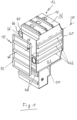
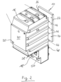
- Fig. 1 shows a gas-insulated container for a medium-voltage switching device (not shown), which has a housing 12 which is sealed gas-tight by a cover 10 in the final assembled state.
- the housing 12 does indeed have various feedthrough openings 16, 18 and 20. However, these are sealed gas-tight after final assembly.
- the housing 12 has a basically cuboid-shaped structure and is composed of four side walls 22, 24, 26 and 28 as well as a front wall 30, which are connected to one another in a gas-tight manner.
- the cover 10, which, like the other components of the housing, is made of sheet metal and has a circumferential bevel 32, serves to seal the housing 12 in a gas-tight manner at its rear.
- the lid 10 is dimensioned such that it can be inserted into the opening formed by the side walls 22 to 28, with the peripheral bevel 32 of the lid 10 resting against all four side walls 22 to 28 when inserted.
- a weld seam can then be produced in a basically known manner between the peripheral bevel 32 and the four side walls 22 to 28, which connects the lid 10 to the walls 22 to 28 and which is circumferential and strip-shaped.
- spaced tie rods in the form of bolts 34 are provided in the area of the weld between the cover 10 and the side walls 22 and 24 ( Fig. 2 and Fig. 3 ).
- the bolts 34 are welded to the cover 10 and can be designed as simple plug bolts or as threaded bolts. Although the bolts 34 are not screwed, designing them as threaded bolts would increase the friction between the bolt and the adjacent component and thus ensure particularly good power transmission.
- a profile rail 36, 38 is welded to each of the two side walls 22 and 24 of the housing 12, which extends at right angles to its side wall and has a total of four holes 40 that serve to insert the tie rods 34.
- the axis of each hole 40 runs parallel to the adjacent wall 22 and 24.
- the hole 40 itself can be designed as an elongated hole, the transverse extent of which is adapted to the cross section of the bolts 34 and is oriented at right angles to the adjacent side wall 22 and 24. This allows manufacturing and production tolerances to be reduced (in Fig. 1 and 2 ) in the vertical direction. At the same time, however, the bolts 34 in the holes 40 in the illustration of Fig. 3 almost free of play.
- the bolts 34 in the holes 40 which act as tension anchors, prevent the side walls 22 and 24 from bulging in the area of the weld seam, since the bolts 34 are inserted into the holes 40 of the profiles 36 and 38.
- reference numerals 42 and 44 designate U-shaped reinforcing rails which are attached to the outside of the housing 12.
- Reference numeral 46 designates similar reinforcing profiles which are welded onto the outside of the cover 10.
- Similar reinforcing profiles 48 are located on a cable connection container 50 which is provided on the underside of the housing 12.
Landscapes
- Engineering & Computer Science (AREA)
- Power Engineering (AREA)
- Driving Mechanisms And Operating Circuits Of Arc-Extinguishing High-Tension Switches (AREA)
- Gas-Insulated Switchgears (AREA)
Description
- Die vorliegende Erfindung betrifft einen gasisolierten Behälter für eine Schalteinrichtung der Mittelspannungstechnik.
- Derartige gasisolierte Behälter unterliegen einem definierten Innendruck, der je nach Anforderung eine hohe Belastung des Materials und insbesondere der vorhandenen Schweißnaht bedeuten kann. So kann es bei einer hohen Druckbelastung zu einer Verformung der Wand und/oder des Deckels des Gehäuses kommen, so dass die Gefahr besteht, dass die vorhandene Schweißnaht aufgrund einer Verformung des Gehäuses undicht wird oder aufreißt.
- Die
CN 103 401 173 A offenbart einen gasisolierten Behälter für eine Schalteinrichtung der Mittelspannungstechnik, der ein von einem Deckel verschlossenes Gehäuse umfasst, wobei der Deckel entlang einer Schweißnaht mit zumindest einer Seitenwand des Gehäuses verschweißt ist. Ferner weist das Gehäuse einen Zuganker auf, der zwischen zwei Längsstreben des Gehäuses befestigt ist. - Die
EP 0 871 269 A1 offenbart einen Behälter für elektrische Schalteinrichtungen, der einen vorderen und einen hinteren Deckel sowie vier Seitenwände aufweist, wobei zwei der Seitenwände durch eine Querverstrebung miteinander verbunden sind. DieEP 3 483 995 A1 offenbart einen gasisolierten Behälter für eine Schalteinrichtung der Mittelspannungstechnik, der innere oder äußere Versteifungsrippen enthält. -
DE 10 2006 032 396 A1 zeigt ein Schaltanlagengehäuse mit an einem Deckel angeschweißten Seitenwänden und mehreren Zugankern.CN 207124409 U undUS 2005/0121418 A1 zeigen andere Konfigurationen von Schaltanlagengehäusen, bei denen Bolzen vorgesehen sind, um den Deckel zu befestigen. - Es ist die Aufgabe der vorliegenden Erfindung, einen gasisolierten Behälter zu schaffen, bei dem auch bei erhöhter Druckbelastung eine Beschädigung der Schweißnaht unterbleibt.
- Die Lösung dieser Aufgabe erfolgt durch die Merkmale des Anspruchs 1.
- Mit Hilfe eines Zugankers kann die Kraft, die durch ein Verformen bzw. Ausbauchen einer Gehäusewand auf die Schweißnaht ausgeübt wird, zuverlässig aufgenommen werden, so dass die Schweißnaht nicht mehr oder nur noch geringfügig belastet wird.
- Vorteilhafte Ausführungsformen der Erfindung sind in der Beschreibung, der Zeichnung sowie den Unteransprüchen beschrieben.
- Nach einer ersten vorteilhaften Ausführungsform kann jeder Zuganker einen an dem Deckel starr befestigten Bolzen umfassen. Dies stellt eine kostengünstige und einfache Möglichkeit dar, die auftretenden Kräfte zuverlässig aufzunehmen.
- Nach einer weiteren vorteilhaften Ausführungsform kann jeder Zuganker an dem Deckel verschweißt sein. Eine solche Befestigungsart ermöglicht einerseits eine gute Kraftübertragung. Andererseits muss keine weitere Abdichtung erfolgen, da der Zuganker nicht durch eine Öffnung oder dergleichen durch den Deckel hindurchgeführt ist.
- Nach einer weiteren vorteilhaften Ausführungsform kann jeder Zuganker in jeweils eine Bohrung eingesteckt sein. Das Einstecken des Zugankers bzw. eines Bolzens zur Montage ermöglicht einen besonders zeitsparenden Zusammenbau des Behälters, da der Deckel vor dem Verschweißen lediglich auf den Behälter aufgesetzt werden muss und hierbei gleichzeitig der Zuganker in die Bohrung des Gehäuses eingesteckt werden kann, um die auftretenden Kräfte aufzunehmen.
- Nach einer weiteren vorteilhaften Ausführungsform können die Bohrungen in einem Profil ausgebildet sein, das im Bereich der Schweißnaht an der Wand befestigt, insbesondere verschweißt ist. Ein solches Profil mit Bohrungen lässt sich auf einfache Weise herstellen und mit derjenigen Wand verbinden, an der die Schweißnaht angeordnet ist. Wenn hierbei die Achse der Bohrung parallel zu dieser Wand verläuft, lässt sich der Deckel durch einfaches Einstecken des Zugankers in die Bohrung montieren und anschließend verschweißen.
- Nach einer weiteren vorteilhaften Ausführungsform können die Bohrungen als Langloch ausgebildet sein, dessen Quererstreckung rechtwinklig zur benachbarten Seitenwand orientiert ist. Durch die Ausbildung als Langloch lassen sich Montage- und Fertigungstoleranzen in einer Richtung parallel zur Schweißnaht kompensieren. Gleichzeitig kann jedoch der Zuganker im Wesentlichen spielfrei in der Bohrung gehalten werden, da die auf den Querschnitt des Zugankers angepasste Quererstreckung des Langlochs rechtwinklig zur Seitenwand orientiert ist.
- Die Schweißnaht zur Befestigung des Deckels kann so ausgebildet sein, dass diese den Deckel mit vier benachbarten Seitenwänden verbindet. Durch eine streifenförmige Ausbildung der Schweißnaht lässt sich eine besonders gute Verbindung erzielen.
- Nach einer weiteren vorteilhaften Ausführungsform können Zuganker nur im Bereich von zwei einander gegenüberliegenden Wänden vorgesehen sein. Wenn die dem Deckel benachbarten Wände des Behälters unterschiedlich groß sind, treten die größten Verformungen bei einer Druckbelastung im Bereich der flächenmäßig größten Wände auf und es kann in einem solchen Fall ausreichend sein, wenn nur im Bereich dieser Wände Zuganker vorgesehen werden.
- Nachfolgend wird die vorliegende Erfindung rein beispielhaft anhand einer vorteilhaften Ausführungsform und unter Bezugnahme auf die beigefügten Zeichnungen beschrieben. Es zeigen:
- Fig. 1
- eine perspektivische Rückansicht eines gasisolierten Behälters;
- Fig. 2
- eine perspektivische Vorderansicht des Behälters von
Fig. 1 ; und - Fig. 3
- einen Schnitt durch den Behälter von
Fig. 1 entlang der Linie A-A. -
Fig. 1 zeigt einen gasisolierten Behälter für eine Schalteinrichtung der Mittelspannungstechnik (nicht dargestellt), der ein im endmontierten Zustand von einem Deckel 10 gasdicht verschlossenes Gehäuse 12 aufweist. In der Darstellung der Figuren besitzt das Gehäuse 12 zwar verschiedene Durchführungsöffnungen 16, 18 und 20. Diese sind jedoch nach erfolgter Endmontage gasdicht abgedichtet. - Das Gehäuse 12 besitzt einen grundsätzlich quaderförmigen Aufbau und ist aus vier Seitenwänden 22, 24, 26 und 28 sowie einer Vorderwand 30 zusammengesetzt, die gasdicht miteinander verbunden sind. Zum gasdichten Verschließen des Gehäuses 12 an seiner Rückseite dient der Deckel 10, der wie auch die anderen Bestandteile des Gehäuses aus Blech hergestellt ist und eine umlaufende Abkantung 32 aufweist.
- Wie insbesondere
Fig. 1 verdeutlicht, ist der Deckel 10 so dimensioniert, dass er in die von den Seitenwänden 22 bis 28 gebildete Öffnung eingeschoben werden kann, wobei die umlaufende Abkantung 32 des Deckels 10 im eingeschobenen Zustand an allen vier Seitenwänden 22 bis 28 anliegt. Nach Einschieben des Deckels kann dann auf grundsätzlich bekannte Art und Weise eine Schweißnaht zwischen der umlaufenden Abkantung 32 und den vier Seitenwänden 22 bis 28 hergestellt werden, die den Deckel 10 mit den Wänden 22 bis 28 verbindet und die umlaufend und streifenförmig ausgebildet ist. - Zum Schutz dieser Schweißnaht, die in den Figuren nicht dargestellt ist, sind im Bereich der Schweißnaht zwischen dem Deckel 10 und den Seitenwänden 22 und 24 beabstandete Zuganker in Form von Bolzen 34 vorgesehen (
Fig. 2 undFig. 3 ). Entlang des Bereichs der Schweißnaht, welcher den Deckel 10 mit der Seitenwand 22 verbindet, befinden sich auf einer Seite vier gleichmäßig voneinander beabstandete Bolzen 34. Das gleiche gilt für den gegenüberliegenden Bereich der Schweißnaht, welcher den Deckel 10 mit der Seitenwand 24 verbindet. Die Bolzen 34 sind an dem Deckel 10 verschweißt und können als einfache Steckbolzen oder aber auch als Gewindebolzen ausgeführt sein. Obwohl die Bolzen 34 nicht verschraubt werden, würde eine Ausbildung als Gewindebolzen die Reibung zwischen dem Bolzen und dem benachbarten Bauteil erhöhen und somit für eine besonders gute Kraftübertragung sorgen. - Zur Aufnahme der Bolzen 34 ist an beiden Seitenwänden 22 und 24 des Gehäuses 12 jeweils eine Profilschiene 36, 38 angeschweißt, die sich rechtwinklig zu ihrer Seitenwand erstreckt und die insgesamt vier Bohrungen 40 aufweist, die für ein Einstecken der Zuganker 34 dienen. Hierbei verläuft die Achse jeder Bohrung 40 parallel zur benachbarten Wand 22 und 24. Die Bohrung 40 selbst kann als Langloch ausgebildet sein, dessen Quererstreckung an den Querschnitt der Bolzen 34 angepasst ist und rechtwinklig zur benachbarten Seitenwand 22 und 24 orientiert ist. Hierdurch lassen sich Herstellungs- und Fertigungstoleranzen in (in
Fig. 1 und2 ) vertikaler Richtung kompensieren. Gleichzeitig sind jedoch die Bolzen 34 in den Bohrungen 40 in der Darstellung vonFig. 3 nahezu spielfrei aufgenommen. Wenn sich demnach die Seitenwände 22 und 24 aufgrund einer Druckbelastung nach außen ausbauchen, verhindern die als Zuganker wirkenden Bolzen 34 in den Bohrungen 40 ein Ausbauchen der Seitenwände 22 und 24 im Bereich der Schweißnaht, da die Bolzen 34 in die Bohrungen 40 der Profile 36 und 38 eingesteckt sind. - In den Figuren bezeichnen die Bezugszeichen 42 und 44 U-förmige Verstärkungsschienen, die an der Außenseite des Gehäuses 12 aufgebracht sind. Mit dem Bezugszeichen 46 sind gleichartige Verstärkungsprofile bezeichnet, die auf die Außenseite des Deckels 10 aufgeschweißt sind. Gleichartige Verstärkungsprofile 48 befinden sich auf einem Kabelanschlussbehälter 50, der an der Unterseite des Gehäuses 12 vorgesehen ist.
Claims (10)
- Gasisolierter Behälter für eine Schalteinrichtung der Mittelspannungstechnik, umfassend ein von einem Deckel (10) verschlossenes Gehäuse (12) und mehrere Zuganker (34),wobei der Deckel (10) entlang einer Schweißnaht mit zumindest einer Seitenwand (22, 24) des Gehäuses (12) verschweißt ist,dadurch gekennzeichnet, dass die mehrere Zuganker (34) im Bereich der Schweißnaht, welche den Deckel (10) mit der Seitenwand (22, 24) verbindet, zwischen Deckel (10) und Seitenwand (22, 24) vorgesehen sind.
- Behälter nach Anspruch 1,
dadurch gekennzeichnet, dass
die Zuganker (34) einen an dem Deckel (10) starr befestigten Bolzen umfassen. - Behälter nach Anspruch 1 oder 2,
dadurch gekennzeichnet, dass
die Zuganker (34) an dem Deckel (10) verschweißt sind. - Behälter nach einem der vorstehenden Ansprüche,
dadurch gekennzeichnet, dass
jeder Zuganker (34) in jeweils eine Bohrung (40) eingesteckt ist. - Behälter nach einem der vorstehenden Ansprüche,
dadurch gekennzeichnet, dass
die Bohrung (40) in einem Profil (36, 38) ausgebildet ist, das an der Seitenwand (22, 24) befestigt, insbesondere verschweißt ist. - Behälter nach Anspruch 5,
dadurch gekennzeichnet, dass
die Achse der Bohrung (40) parallel zur benachbarten Seitenwand (22, 24) verläuft. - Behälter nach einem der vorstehenden Ansprüche 4 - 6,
dadurch gekennzeichnet, dass
die Bohrung (40) als Langloch ausgebildet ist, dessen Quererstreckung rechtwinklig zur benachbarten Seitenwand (22, 24) orientiert ist. - Behälter nach einem der vorstehenden Ansprüche,
dadurch gekennzeichnet, dass
die Schweißnaht den Deckel (10) mit vier Seitenwänden (22, 24) verbindet. - Behälter nach einem der vorstehenden Ansprüche,
dadurch gekennzeichnet, dass
die Schweißnaht streifenförmig ausgebildet ist. - Behälter nach einem der vorstehenden Ansprüche,
dadurch gekennzeichnet, dass
Zuganker (34) nur im Bereich von zwei einander gegenüber liegenden Seitenwänden (22, 24) vorgesehen sind.
Applications Claiming Priority (1)
| Application Number | Priority Date | Filing Date | Title |
|---|---|---|---|
| DE102019114570.8A DE102019114570A1 (de) | 2019-05-29 | 2019-05-29 | Gasisolierter Behälter |
Publications (2)
| Publication Number | Publication Date |
|---|---|
| EP3745548A1 EP3745548A1 (de) | 2020-12-02 |
| EP3745548B1 true EP3745548B1 (de) | 2025-03-05 |
Family
ID=70285422
Family Applications (1)
| Application Number | Title | Priority Date | Filing Date |
|---|---|---|---|
| EP20167357.1A Active EP3745548B1 (de) | 2019-05-29 | 2020-03-31 | Gasisolierter behälter |
Country Status (4)
| Country | Link |
|---|---|
| EP (1) | EP3745548B1 (de) |
| CN (1) | CN112018653A (de) |
| DE (1) | DE102019114570A1 (de) |
| ES (1) | ES3018132T3 (de) |
Families Citing this family (2)
| Publication number | Priority date | Publication date | Assignee | Title |
|---|---|---|---|---|
| DE102021102705A1 (de) * | 2021-02-05 | 2022-08-11 | Schneider Electric Industries Sas | Druckbehälter |
| DE102023102362A1 (de) * | 2023-01-31 | 2024-08-01 | Schneider Electric Industries Sas | Druckbehälter |
Citations (3)
| Publication number | Priority date | Publication date | Assignee | Title |
|---|---|---|---|---|
| US20050121418A1 (en) * | 2003-12-08 | 2005-06-09 | Mitsubishi Denki Kabushiki Kaisha | Gas-insulated switchgear |
| DE102006032396A1 (de) * | 2006-07-07 | 2008-01-10 | Siemens Ag | Behälter für eine Schaltanlage der Energieversorgung und -verteilung |
| CN207124409U (zh) * | 2017-08-31 | 2018-03-20 | 青岛特锐德电气股份有限公司 | 一种侧母线扩展气体绝缘金属封闭开关设备 |
Family Cites Families (12)
| Publication number | Priority date | Publication date | Assignee | Title |
|---|---|---|---|---|
| EP0068473B1 (de) * | 1981-07-01 | 1985-10-30 | Gerhard KG | Druckfester Tank |
| FR2761824B1 (fr) * | 1997-04-08 | 1999-05-14 | Gec Alsthom T & D Sa | Caisson metallique etanche pour cellule de distribution d'energie electrique |
| CN201131095Y (zh) * | 2007-12-25 | 2008-10-08 | 广西银河迪康电气有限公司 | 一种共箱式环网柜后板与内格板连接机构 |
| CN201229955Y (zh) * | 2008-07-04 | 2009-04-29 | 天津力神电池股份有限公司 | 适用于电动自行车的锂离子电池组外壳 |
| CN102271473B (zh) * | 2010-06-03 | 2015-11-25 | 鸿富锦精密工业(武汉)有限公司 | 电子装置的壳体 |
| FR2969405A1 (fr) * | 2010-12-15 | 2012-06-22 | Areva T & D Sas | Dispositif de liaison electrique a isolation gazeuse a duree de vie amelioree |
| CN103401173B (zh) * | 2013-07-30 | 2016-02-03 | 上海天灵开关厂有限公司 | 一种气体绝缘断路器共箱安装柜 |
| CN204597336U (zh) * | 2015-04-16 | 2015-08-26 | 湖州罗芙科技有限公司 | 一种氮气环网柜后板与内板的连接装置 |
| CN206575073U (zh) * | 2017-02-05 | 2017-10-20 | 常州太平洋电力设备(集团)有限公司 | 电力机车用气体绝缘高压开关设备箱 |
| CN206585262U (zh) * | 2017-03-03 | 2017-10-24 | 南京海兴电网技术有限公司 | 一种防止充气式环网柜气箱变形的拉杆 |
| EP3483995B1 (de) * | 2017-11-14 | 2022-09-21 | ABB Schweiz AG | Gasisolierte mittelspannungsschaltanlage mit druckverstärktem gehäuse |
| CN109301732A (zh) * | 2018-11-15 | 2019-02-01 | 长沙瑞联材料科技有限公司 | 一种防尘配电箱盒 |
-
2019
- 2019-05-29 DE DE102019114570.8A patent/DE102019114570A1/de active Pending
-
2020
- 2020-03-31 ES ES20167357T patent/ES3018132T3/es active Active
- 2020-03-31 EP EP20167357.1A patent/EP3745548B1/de active Active
- 2020-05-12 CN CN202010396142.XA patent/CN112018653A/zh active Pending
Patent Citations (3)
| Publication number | Priority date | Publication date | Assignee | Title |
|---|---|---|---|---|
| US20050121418A1 (en) * | 2003-12-08 | 2005-06-09 | Mitsubishi Denki Kabushiki Kaisha | Gas-insulated switchgear |
| DE102006032396A1 (de) * | 2006-07-07 | 2008-01-10 | Siemens Ag | Behälter für eine Schaltanlage der Energieversorgung und -verteilung |
| CN207124409U (zh) * | 2017-08-31 | 2018-03-20 | 青岛特锐德电气股份有限公司 | 一种侧母线扩展气体绝缘金属封闭开关设备 |
Also Published As
| Publication number | Publication date |
|---|---|
| CN112018653A (zh) | 2020-12-01 |
| DE102019114570A1 (de) | 2020-12-03 |
| EP3745548A1 (de) | 2020-12-02 |
| ES3018132T3 (en) | 2025-05-14 |
Similar Documents
| Publication | Publication Date | Title |
|---|---|---|
| EP3008370B1 (de) | Spann- oder rohrschelle | |
| DE2556048A1 (de) | Skelett fuer metallschrank | |
| DE29917734U1 (de) | Aus einem Profilelement gebildete Montageschiene | |
| DD148695A5 (de) | Feuersichere leitungsdurchfuehrung | |
| DE2829671A1 (de) | Eckverbindung fuer die einen ueberrollschutz an fahrzeugen bildenden, in einer ecke zusammenstossenden traeger, streben, stuetzen o.dgl. | |
| DE102010035792A1 (de) | Rahmenschenkel für ein Schaltschrankgestell | |
| EP3652831A1 (de) | Zugentlastungstülle | |
| DE3034512A1 (de) | Frachtcontainer | |
| EP3745548A1 (de) | Gasisolierter behälter | |
| EP2060680A1 (de) | Stütze für Hochwasserschutzwand | |
| DE10060636A1 (de) | Vorrichtung zum Aufnehmen von Stoßenergie | |
| WO2022167491A1 (de) | Druckbehälter | |
| DE102018126524B3 (de) | Querträger für den Kraftfahrzeugbau | |
| DE19756869A1 (de) | Dämmvorrichtung mit Dammbalkenstütze und Verriegelungseinrichtung | |
| WO2010006459A1 (de) | Sitzeinheit und sitzbank | |
| DE19724136C2 (de) | Abdichtende Rohr- und Kabeldurchführung | |
| EP0461336A2 (de) | Verfahren zur Herstellung einer Druckkammer mit Widerstandfähigkeit gegen innere Detonationen, und gemäss diesem Verfahren hergestellte Druckkammer | |
| EP2762659B1 (de) | Montage- und Reparatureinrichtung | |
| DE29813558U1 (de) | Abgedichtete Durchführung von Leitungen durch eine wand- oder plattenartige Struktur, insbesondere eines Schienenfahrzeuges | |
| DE102018008357A1 (de) | Verdrehsicherung für eine Antriebsrolle | |
| EP3611307A1 (de) | Schienenanordnung | |
| DE2346284C3 (de) | Eck- oder Fugenleistenanordming | |
| DE29709983U1 (de) | Abdichtende Rohr- und Kabeldurchführung | |
| DE1684926C3 (de) | Deckel für Kernreaktordruckbehälter aus Stahlbeton | |
| DE1987675U (de) | Lagertank. |
Legal Events
| Date | Code | Title | Description |
|---|---|---|---|
| PUAI | Public reference made under article 153(3) epc to a published international application that has entered the european phase |
Free format text: ORIGINAL CODE: 0009012 |
|
| STAA | Information on the status of an ep patent application or granted ep patent |
Free format text: STATUS: THE APPLICATION HAS BEEN PUBLISHED |
|
| AK | Designated contracting states |
Kind code of ref document: A1 Designated state(s): AL AT BE BG CH CY CZ DE DK EE ES FI FR GB GR HR HU IE IS IT LI LT LU LV MC MK MT NL NO PL PT RO RS SE SI SK SM TR |
|
| AX | Request for extension of the european patent |
Extension state: BA ME |
|
| STAA | Information on the status of an ep patent application or granted ep patent |
Free format text: STATUS: REQUEST FOR EXAMINATION WAS MADE |
|
| 17P | Request for examination filed |
Effective date: 20210531 |
|
| RBV | Designated contracting states (corrected) |
Designated state(s): AL AT BE BG CH CY CZ DE DK EE ES FI FR GB GR HR HU IE IS IT LI LT LU LV MC MK MT NL NO PL PT RO RS SE SI SK SM TR |
|
| STAA | Information on the status of an ep patent application or granted ep patent |
Free format text: STATUS: EXAMINATION IS IN PROGRESS |
|
| 17Q | First examination report despatched |
Effective date: 20221220 |
|
| GRAP | Despatch of communication of intention to grant a patent |
Free format text: ORIGINAL CODE: EPIDOSNIGR1 |
|
| STAA | Information on the status of an ep patent application or granted ep patent |
Free format text: STATUS: GRANT OF PATENT IS INTENDED |
|
| INTG | Intention to grant announced |
Effective date: 20241008 |
|
| GRAS | Grant fee paid |
Free format text: ORIGINAL CODE: EPIDOSNIGR3 |
|
| GRAA | (expected) grant |
Free format text: ORIGINAL CODE: 0009210 |
|
| STAA | Information on the status of an ep patent application or granted ep patent |
Free format text: STATUS: THE PATENT HAS BEEN GRANTED |
|
| AK | Designated contracting states |
Kind code of ref document: B1 Designated state(s): AL AT BE BG CH CY CZ DE DK EE ES FI FR GB GR HR HU IE IS IT LI LT LU LV MC MK MT NL NO PL PT RO RS SE SI SK SM TR |
|
| REG | Reference to a national code |
Ref country code: GB Ref legal event code: FG4D Free format text: NOT ENGLISH |
|
| REG | Reference to a national code |
Ref country code: CH Ref legal event code: EP |
|
| REG | Reference to a national code |
Ref country code: IE Ref legal event code: FG4D Free format text: LANGUAGE OF EP DOCUMENT: GERMAN |
|
| REG | Reference to a national code |
Ref country code: DE Ref legal event code: R096 Ref document number: 502020010516 Country of ref document: DE |
|
| PG25 | Lapsed in a contracting state [announced via postgrant information from national office to epo] |
Ref country code: RS Free format text: LAPSE BECAUSE OF FAILURE TO SUBMIT A TRANSLATION OF THE DESCRIPTION OR TO PAY THE FEE WITHIN THE PRESCRIBED TIME-LIMIT Effective date: 20250605 |
|
| PG25 | Lapsed in a contracting state [announced via postgrant information from national office to epo] |
Ref country code: FI Free format text: LAPSE BECAUSE OF FAILURE TO SUBMIT A TRANSLATION OF THE DESCRIPTION OR TO PAY THE FEE WITHIN THE PRESCRIBED TIME-LIMIT Effective date: 20250305 |
|
| REG | Reference to a national code |
Ref country code: NL Ref legal event code: MP Effective date: 20250305 |
|
| PGFP | Annual fee paid to national office [announced via postgrant information from national office to epo] |
Ref country code: ES Payment date: 20250410 Year of fee payment: 6 |
|
| REG | Reference to a national code |
Ref country code: LT Ref legal event code: MG9D |
|
| PG25 | Lapsed in a contracting state [announced via postgrant information from national office to epo] |
Ref country code: NO Free format text: LAPSE BECAUSE OF FAILURE TO SUBMIT A TRANSLATION OF THE DESCRIPTION OR TO PAY THE FEE WITHIN THE PRESCRIBED TIME-LIMIT Effective date: 20250605 |
|
| PG25 | Lapsed in a contracting state [announced via postgrant information from national office to epo] |
Ref country code: HR Free format text: LAPSE BECAUSE OF FAILURE TO SUBMIT A TRANSLATION OF THE DESCRIPTION OR TO PAY THE FEE WITHIN THE PRESCRIBED TIME-LIMIT Effective date: 20250305 |
|
| PG25 | Lapsed in a contracting state [announced via postgrant information from national office to epo] |
Ref country code: LV Free format text: LAPSE BECAUSE OF FAILURE TO SUBMIT A TRANSLATION OF THE DESCRIPTION OR TO PAY THE FEE WITHIN THE PRESCRIBED TIME-LIMIT Effective date: 20250305 |
|
| PG25 | Lapsed in a contracting state [announced via postgrant information from national office to epo] |
Ref country code: GR Free format text: LAPSE BECAUSE OF FAILURE TO SUBMIT A TRANSLATION OF THE DESCRIPTION OR TO PAY THE FEE WITHIN THE PRESCRIBED TIME-LIMIT Effective date: 20250606 Ref country code: BG Free format text: LAPSE BECAUSE OF FAILURE TO SUBMIT A TRANSLATION OF THE DESCRIPTION OR TO PAY THE FEE WITHIN THE PRESCRIBED TIME-LIMIT Effective date: 20250305 |
|
| PG25 | Lapsed in a contracting state [announced via postgrant information from national office to epo] |
Ref country code: NL Free format text: LAPSE BECAUSE OF FAILURE TO SUBMIT A TRANSLATION OF THE DESCRIPTION OR TO PAY THE FEE WITHIN THE PRESCRIBED TIME-LIMIT Effective date: 20250305 |
|
| PG25 | Lapsed in a contracting state [announced via postgrant information from national office to epo] |
Ref country code: SE Free format text: LAPSE BECAUSE OF FAILURE TO SUBMIT A TRANSLATION OF THE DESCRIPTION OR TO PAY THE FEE WITHIN THE PRESCRIBED TIME-LIMIT Effective date: 20250305 |
|
| PG25 | Lapsed in a contracting state [announced via postgrant information from national office to epo] |
Ref country code: SM Free format text: LAPSE BECAUSE OF FAILURE TO SUBMIT A TRANSLATION OF THE DESCRIPTION OR TO PAY THE FEE WITHIN THE PRESCRIBED TIME-LIMIT Effective date: 20250305 |
|
| PG25 | Lapsed in a contracting state [announced via postgrant information from national office to epo] |
Ref country code: PT Free format text: LAPSE BECAUSE OF FAILURE TO SUBMIT A TRANSLATION OF THE DESCRIPTION OR TO PAY THE FEE WITHIN THE PRESCRIBED TIME-LIMIT Effective date: 20250707 |
|
| PG25 | Lapsed in a contracting state [announced via postgrant information from national office to epo] |
Ref country code: IT Free format text: LAPSE BECAUSE OF FAILURE TO SUBMIT A TRANSLATION OF THE DESCRIPTION OR TO PAY THE FEE WITHIN THE PRESCRIBED TIME-LIMIT Effective date: 20250305 Ref country code: PL Free format text: LAPSE BECAUSE OF FAILURE TO SUBMIT A TRANSLATION OF THE DESCRIPTION OR TO PAY THE FEE WITHIN THE PRESCRIBED TIME-LIMIT Effective date: 20250305 |
|
| PG25 | Lapsed in a contracting state [announced via postgrant information from national office to epo] |
Ref country code: CZ Free format text: LAPSE BECAUSE OF FAILURE TO SUBMIT A TRANSLATION OF THE DESCRIPTION OR TO PAY THE FEE WITHIN THE PRESCRIBED TIME-LIMIT Effective date: 20250305 Ref country code: EE Free format text: LAPSE BECAUSE OF FAILURE TO SUBMIT A TRANSLATION OF THE DESCRIPTION OR TO PAY THE FEE WITHIN THE PRESCRIBED TIME-LIMIT Effective date: 20250305 |
|
| REG | Reference to a national code |
Ref country code: CH Ref legal event code: H13 Free format text: ST27 STATUS EVENT CODE: U-0-0-H10-H13 (AS PROVIDED BY THE NATIONAL OFFICE) Effective date: 20251023 |
|
| PG25 | Lapsed in a contracting state [announced via postgrant information from national office to epo] |
Ref country code: RO Free format text: LAPSE BECAUSE OF FAILURE TO SUBMIT A TRANSLATION OF THE DESCRIPTION OR TO PAY THE FEE WITHIN THE PRESCRIBED TIME-LIMIT Effective date: 20250305 |
|
| PG25 | Lapsed in a contracting state [announced via postgrant information from national office to epo] |
Ref country code: SK Free format text: LAPSE BECAUSE OF FAILURE TO SUBMIT A TRANSLATION OF THE DESCRIPTION OR TO PAY THE FEE WITHIN THE PRESCRIBED TIME-LIMIT Effective date: 20250305 |
|
| PG25 | Lapsed in a contracting state [announced via postgrant information from national office to epo] |
Ref country code: IS Free format text: LAPSE BECAUSE OF FAILURE TO SUBMIT A TRANSLATION OF THE DESCRIPTION OR TO PAY THE FEE WITHIN THE PRESCRIBED TIME-LIMIT Effective date: 20250705 |
|
| PG25 | Lapsed in a contracting state [announced via postgrant information from national office to epo] |
Ref country code: LU Free format text: LAPSE BECAUSE OF NON-PAYMENT OF DUE FEES Effective date: 20250331 |
|
| REG | Reference to a national code |
Ref country code: DE Ref legal event code: R097 Ref document number: 502020010516 Country of ref document: DE |
|
| REG | Reference to a national code |
Ref country code: BE Ref legal event code: MM Effective date: 20250331 |
|
| PG25 | Lapsed in a contracting state [announced via postgrant information from national office to epo] |
Ref country code: MC Free format text: LAPSE BECAUSE OF FAILURE TO SUBMIT A TRANSLATION OF THE DESCRIPTION OR TO PAY THE FEE WITHIN THE PRESCRIBED TIME-LIMIT Effective date: 20250305 |
|
| PLBE | No opposition filed within time limit |
Free format text: ORIGINAL CODE: 0009261 |
|
| STAA | Information on the status of an ep patent application or granted ep patent |
Free format text: STATUS: NO OPPOSITION FILED WITHIN TIME LIMIT |
|
| PG25 | Lapsed in a contracting state [announced via postgrant information from national office to epo] |
Ref country code: DK Free format text: LAPSE BECAUSE OF FAILURE TO SUBMIT A TRANSLATION OF THE DESCRIPTION OR TO PAY THE FEE WITHIN THE PRESCRIBED TIME-LIMIT Effective date: 20250305 |
|
| REG | Reference to a national code |
Ref country code: CH Ref legal event code: L10 Free format text: ST27 STATUS EVENT CODE: U-0-0-L10-L00 (AS PROVIDED BY THE NATIONAL OFFICE) Effective date: 20260114 |
|
| PG25 | Lapsed in a contracting state [announced via postgrant information from national office to epo] |
Ref country code: BE Free format text: LAPSE BECAUSE OF NON-PAYMENT OF DUE FEES Effective date: 20250331 |
|
| PG25 | Lapsed in a contracting state [announced via postgrant information from national office to epo] |
Ref country code: CH Free format text: LAPSE BECAUSE OF NON-PAYMENT OF DUE FEES Effective date: 20250331 |
|
| PG25 | Lapsed in a contracting state [announced via postgrant information from national office to epo] |
Ref country code: IE Free format text: LAPSE BECAUSE OF NON-PAYMENT OF DUE FEES Effective date: 20250331 |
|
| 26N | No opposition filed |
Effective date: 20251208 |
|
| PGFP | Annual fee paid to national office [announced via postgrant information from national office to epo] |
Ref country code: GB Payment date: 20260324 Year of fee payment: 7 |
|
| PGFP | Annual fee paid to national office [announced via postgrant information from national office to epo] |
Ref country code: DE Payment date: 20260204 Year of fee payment: 7 |
|
| PGFP | Annual fee paid to national office [announced via postgrant information from national office to epo] |
Ref country code: FR Payment date: 20260323 Year of fee payment: 7 |