EP3745558B9 - Dispositif et procédé permettant d'exécuter une correction de puissance dans un système de transmission de puissance sans fil - Google Patents
Dispositif et procédé permettant d'exécuter une correction de puissance dans un système de transmission de puissance sans fil Download PDFInfo
- Publication number
- EP3745558B9 EP3745558B9 EP20743047.1A EP20743047A EP3745558B9 EP 3745558 B9 EP3745558 B9 EP 3745558B9 EP 20743047 A EP20743047 A EP 20743047A EP 3745558 B9 EP3745558 B9 EP 3745558B9
- Authority
- EP
- European Patent Office
- Prior art keywords
- power
- wireless power
- packet
- wireless
- calibration
- Prior art date
- Legal status (The legal status is an assumption and is not a legal conclusion. Google has not performed a legal analysis and makes no representation as to the accuracy of the status listed.)
- Active
Links
Images


















Classifications
-
- H—ELECTRICITY
- H02—GENERATION; CONVERSION OR DISTRIBUTION OF ELECTRIC POWER
- H02J—ELECTRIC POWER NETWORKS; CIRCUIT ARRANGEMENTS OR SYSTEMS FOR SUPPLYING OR DISTRIBUTING ELECTRIC POWER; SYSTEMS FOR STORING ELECTRIC ENERGY
- H02J50/00—Circuit arrangements or systems for wireless supply or distribution of electric power
- H02J50/10—Circuit arrangements or systems for wireless supply or distribution of electric power using inductive coupling
-
- H—ELECTRICITY
- H02—GENERATION; CONVERSION OR DISTRIBUTION OF ELECTRIC POWER
- H02J—ELECTRIC POWER NETWORKS; CIRCUIT ARRANGEMENTS OR SYSTEMS FOR SUPPLYING OR DISTRIBUTING ELECTRIC POWER; SYSTEMS FOR STORING ELECTRIC ENERGY
- H02J50/00—Circuit arrangements or systems for wireless supply or distribution of electric power
- H02J50/40—Circuit arrangements or systems for wireless supply or distribution of electric power using two or more transmitting or receiving devices
-
- H—ELECTRICITY
- H02—GENERATION; CONVERSION OR DISTRIBUTION OF ELECTRIC POWER
- H02J—ELECTRIC POWER NETWORKS; CIRCUIT ARRANGEMENTS OR SYSTEMS FOR SUPPLYING OR DISTRIBUTING ELECTRIC POWER; SYSTEMS FOR STORING ELECTRIC ENERGY
- H02J50/00—Circuit arrangements or systems for wireless supply or distribution of electric power
- H02J50/60—Circuit arrangements or systems for wireless supply or distribution of electric power responsive to the presence of foreign objects, e.g. detection of living beings
-
- H—ELECTRICITY
- H02—GENERATION; CONVERSION OR DISTRIBUTION OF ELECTRIC POWER
- H02J—ELECTRIC POWER NETWORKS; CIRCUIT ARRANGEMENTS OR SYSTEMS FOR SUPPLYING OR DISTRIBUTING ELECTRIC POWER; SYSTEMS FOR STORING ELECTRIC ENERGY
- H02J50/00—Circuit arrangements or systems for wireless supply or distribution of electric power
- H02J50/80—Circuit arrangements or systems for wireless supply or distribution of electric power involving the exchange of data, concerning supply or distribution of electric power, between transmitting devices and receiving devices
-
- H—ELECTRICITY
- H04—ELECTRIC COMMUNICATION TECHNIQUE
- H04L—TRANSMISSION OF DIGITAL INFORMATION, e.g. TELEGRAPHIC COMMUNICATION
- H04L1/00—Arrangements for detecting or preventing errors in the information received
- H04L1/12—Arrangements for detecting or preventing errors in the information received by using return channel
- H04L1/16—Arrangements for detecting or preventing errors in the information received by using return channel in which the return channel carries supervisory signals, e.g. repetition request signals
-
- H—ELECTRICITY
- H02—GENERATION; CONVERSION OR DISTRIBUTION OF ELECTRIC POWER
- H02J—ELECTRIC POWER NETWORKS; CIRCUIT ARRANGEMENTS OR SYSTEMS FOR SUPPLYING OR DISTRIBUTING ELECTRIC POWER; SYSTEMS FOR STORING ELECTRIC ENERGY
- H02J50/00—Circuit arrangements or systems for wireless supply or distribution of electric power
- H02J50/10—Circuit arrangements or systems for wireless supply or distribution of electric power using inductive coupling
- H02J50/12—Circuit arrangements or systems for wireless supply or distribution of electric power using inductive coupling of the resonant type
Definitions
- the present disclosure relates to wireless charging and, more particularly, to an apparatus and method for performing power calibration in a wireless power transfer system.
- the wireless power transfer (or transmission) technology corresponds to a technology that may wirelessly transfer (or transmit) power between a power source and an electronic device.
- a wireless device such as a smartphone or a tablet PC, and so on
- the wireless power transfer technique may provide more outstanding mobility, convenience, and safety as compared to the conventional wired charging environment, which uses a wired charging connector.
- the wireless power transfer technique is raising attention as a replacement for the conventional wired power transfer environment in diverse fields, such as electric vehicles, Bluetooth earphones, 3D glasses, diverse wearable devices, household (or home) electric appliances, furniture, underground facilities, buildings, medical equipment, robots, leisure, and so on.
- the wireless power transfer (or transmission) method is also referred to as a contactless power transfer method, or a no point of contact power transfer method, or a wireless charging method.
- a wireless power transfer system may be configured of a wireless power transmitter supplying electric energy by using a wireless power transfer method, and a wireless power receiver receiving the electric energy being supplied by the wireless power transmitter and supplying the receiving electric energy to a receiver, such as a battery cell, and so on.
- the wireless power transfer technique includes diverse methods, such as a method of transferring power by using magnetic coupling, a method of transferring power by using radio frequency (RF), a method of transferring power by using microwaves, and a method of transferring power by using ultrasound (or ultrasonic waves).
- the method that is based on magnetic coupling is categorized as a magnetic induction method and a magnetic resonance method.
- the magnetic induction method corresponds to a method transmitting power by using electric currents that are induced to the coil of the receiver by a magnetic field, which is generated from a coil battery cell of the transmitter, in accordance with an electromagnetic coupling between a transmitting coil and a receiving coil.
- the magnetic resonance method is similar to the magnetic induction method in that is uses a magnetic field. However, the magnetic resonance method is different from the magnetic induction method in that energy is transmitted due to a concentration of magnetic fields on both a transmitting end and a receiving end, which is caused by the generated resonance.
- the wireless power transmitter and the wireless power receiver include various circuit components therein and configure independent devices, but since wireless power is transmitted therebetween by magnetic coupling, the wireless power transmitter and the wireless power receiver configure a single wireless power transfer system. However, there may be an error between transmitted power and reception power due to a change in magnetic coupling based on actual usage environments of the transmitter (Tx) and the receiver (Rx) (magnitudes, frequencies, and duty cycles of signals applied to the wireless power transfer system, distances/position alignment between the transmitter and the receiver, etc.). Such an error may be an obstacle to elaborate foreign object detection (FOD).
- FOD foreign object detection
- EP 2 909 917 A1 describes an inductive power transfer system in accordance with the Qi wireless power transfer standard.
- a calibrator is provided to perform a power loss calibration in order to determine the expected relationship between received power indications and transmitted power indications.
- the calibrator performs a power loss calibration wherein compensation values are performed for a first set or interval of power levels. At this low power level, a default or nominal expected relationship can be used to detect whether unacceptable unaccounted for power loss is experienced.
- the calibrator can proceed to adapt the expected relationship to provide a more accurate indication of the relationship between transmitted power indications and received power indications.
- the calibrator may then proceed to perform a second power loss calibration operation for a second set or interval of power levels. During this second calibration operation, the detector continues to monitor for parasitic power losses that are unacceptably high by using the expected relationship that resulted from the first calibration operation.
- the present disclosure provides an apparatus and method for performing power calibration in a wireless power transfer system.
- the present disclosure also provides an apparatus and method for adaptively calibrating power in response to a load change and performing foreign object detection (FOD).
- FOD foreign object detection
- the present disclosure also provides an apparatus and method for adaptively calibrating power in response to a change in magnetic coupling between a wireless power transmitter and a wireless power receiver and performing FOD.
- a wireless power transmitter according to the present invention is set out in claim 1.
- a wireless power receiver according to the present invention is set out in claim 4.
- a wireless power transmitter includes: a power conversion unit configured to transmit, to a wireless power receiver, wireless power generated based on magnetic coupling in a power transfer phase; and a communication/control unit configured to receive, from the wireless power receiver operating at a first operating point, a first received power packet of the first operating point and a second received power packet of the first operating point related to power calibration and construct a first power calibration curve based on the first received power packet of the first operating point and the second received power packet of the first operating point and configured to receive, from the wireless power receiver operating at a second operating point, a first received power packet of the second operating point and a second received power packet of the second operating point related to power calibration and construct a second power calibration curve based on the first received power packet of the second operating point and the second received power packet of the second operating point.
- a wireless power receiver includes: a power conversion unit configured to receive, from a wireless power transmitter, wireless power generated based on magnetic coupling in a power transfer phase; and a communication/control unit configured to operate at a first operating point and to transmit, to the wireless power transmitter, a first received power packet of the first operating point and a second received power packet of the first operating point related to power calibration and configured to transmit, to the wireless power transmitter, a first received power packet of a second operating point and a second received power packet of the second operating point related to power calibration when an operating power is switched from the first operating point to the second operating point.
- Transmission power and reception power are calibrated by adaptively responding to a newly changed wireless charging environment and power loss is detected based thereon, thereby enabling more sophisticated FOD.
- At least one of A and B may refer to “only A”, “only B”, or “both A and B”.
- the expression of “at least one of A or B” or “at least one of A and/or B” may be interpreted to be the same as “at least one of A and B”.
- At least one of A, B and C may refer to “only A”, “only B”, “only C”, or “any combination of A, B and C”. Also, “at least one of A, B or C” or “at least one of A, B and/or C” may refer to “at least one of A, B and C”.
- the basic principle of the wireless power transfer technique includes, for example, all of a method of transferring power by using magnetic coupling, a method of transferring power by using radio frequency (RF), a method of transferring power by using microwaves, and a method of transferring power by using ultrasound (or ultrasonic waves).
- RF radio frequency
- microwaves a method of transferring power by using microwaves
- ultrasound or ultrasonic waves
- FIG. 1 is a block diagram of a wireless power system (10) according to an exemplary embodiment of the present disclosure.
- the wireless power system (10) include a wireless power transmitter (100) and a wireless power receiver (200).
- the wireless power transmitter (100) and the wireless power receiver (200) may transceive (transmit and/or receive) diverse information that is required for the wireless power transfer.
- communication between the wireless power transmitter (100) and the wireless power receiver (200) may be performed (or established) in accordance with any one of an in-band communication, which uses a magnetic field that is used for the wireless power transfer (or transmission), and an out-band communication, which uses a separate communication carrier.
- Out-band communication may also be referred to as out-of-band communication.
- out-band communication will be largely described. Examples of out-band communication may include NFC, Bluetooth, Bluetooth low energy (BLE), and the like.
- the wireless power transmitter (100) may be provided as a fixed type or a mobile (or portable) type.
- the fixed transmitter type may include an embedded type, which is embedded in in-door ceilings or wall surfaces or embedded in furniture, such as tables, an implanted type, which is installed in out-door parking lots, bus stops, subway stations, and so on, or being installed in means of transportation, such as vehicles or trains.
- the mobile (or portable) type wireless power transmitter (100) may be implemented as a part of another device, such as a mobile device having a portable size or weight or a cover of a laptop computer, and so on.
- the wireless power receiver (200) should be interpreted as a comprehensive concept including diverse home appliances and devices that are operated by being wirelessly supplied with power instead of diverse electronic devices being equipped with a battery and a power cable.
- Typical examples of the wireless power receiver (200) may include portable terminals, cellular phones, smartphones, personal digital assistants (PDAs), portable media players (PDPs), Wibro terminals, tablet PCs, phablet, laptop computers, digital cameras, navigation terminals, television, electronic vehicles (EVs), and so on.
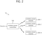
- FIG. 2 is a block diagram of a wireless power system (10) according to another exemplary embodiment of the present disclosure.
- one wireless power receiver (200) or a plurality of wireless power receivers may exist. Although it is shown in FIG. 1 that the wireless power transmitter (100) and the wireless power receiver (200) send and receive power to and from one another in a one-to-one correspondence (or relationship), as shown in FIG. 2 , it is also possible for one wireless power transmitter (100) to simultaneously transfer power to multiple wireless power receivers (200-1, 200-2, ..., 200-M).
- one wireless power transmitter (100) may transfer power to multiple wireless power receivers (200-1, 200-2, ..., 200-M) by using a synchronized transport (or transfer) method or a time-division transport (or transfer) method.
- the wireless power system (10) may also be equipped with a separate wireless power transceiver, such as a relay or repeater, for increasing a wireless power transport distance between the wireless power transmitter (100) and the wireless power receiver (200).
- a separate wireless power transceiver such as a relay or repeater
- power is delivered to the wireless power transceiver from the wireless power transmitter (100), and, then, the wireless power transceiver may transfer the received power to the wireless power receiver (200).
- wireless power receiver power receiver, and receiver, which are mentioned in this specification, will refer to the wireless power receiver (200).
- wireless power transmitter, power transmitter, and transmitter which are mentioned in this specification, will refer to the wireless power transmitter (100).
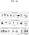
- the electronic devices included in the wireless power transfer system are sorted in accordance with the amount of transmitted power and the amount of received power.
- wearable devices such as smart watches, smart glasses, head mounted displays (HMDs), smart rings, and so on
- mobile electronic devices or portable electronic devices
- earphones, remote controllers, smartphones, PDAs, tablet PCs, and so on may adopt a low-power (approximately 5W or less or approximately 20W or less) wireless charging method.
- Small-sized/Mid-sized electronic devices such as laptop computers, robot vacuum cleaners, TV receivers, audio devices, vacuum cleaners, monitors, and so on, may adopt a mid-power (approximately 50W or less or approximately 200W or less) wireless charging method.
- Kitchen appliances such as mixers, microwave ovens, electric rice cookers, and so on, and personal transportation devices (or other electric devices or means of transportation), such as powered wheelchairs, powered kick scooters, powered bicycles, electric cars, and so on may adopt a high-power (approximately 2kW or less or approximately 22kW or less) wireless charging method.
- the electric devices or means of transportation which are described above (or shown in FIG. 1 ) may each include a wireless power receiver, which will hereinafter be described in detail. Therefore, the above-described electric devices or means of transportation may be charged (or re-charged) by wirelessly receiving power from a wireless power transmitter.
- a standard for the wireless power transfer (or transmission) includes a wireless power consortium (WPC), an air fuel alliance (AFA), and a power matters alliance (PMA).
- WPC wireless power consortium
- AFA air fuel alliance
- PMA power matters alliance
- the WPC standard defines a baseline power profile (BPP) and an extended power profile (EPP).
- BPP baseline power profile
- EPP extended power profile
- the BPP is related to a wireless power transmitter and a wireless power receiver supporting a power transfer of 5W
- the EPP is related to a wireless power transmitter and a wireless power receiver supporting the transfer of a power range greater than 5W and less than 30W.
- the WPC may categorize (or sort) the wireless power transmitters and the wireless power receivers as PC-1, PC0, PC1, and PC2, and the WPC may provide a standard document (or specification) for each power class (PC).
- the PC-1 standard relates to wireless power transmitters and receivers providing a guaranteed power of less than 5W.
- the application of PC-1 includes wearable devices, such as smart watches.
- the PC0 standard relates to wireless power transmitters and receivers providing a guaranteed power of 5W.
- the PC0 standard includes an EPP having a guaranteed power ranges that extends to 30W.
- in-band (IB) communication corresponds to a mandatory communication protocol of PC0
- out-of-band (OB) communication that is used as an optional backup channel may also be used for PC0.
- the wireless power receiver may be identified by setting up an OB flag, which indicates whether or not the OB is supported, within a configuration packet.
- a wireless power transmitter supporting the OB may enter an OB handover phase by transmitting a bit-pattern for an OB handover as a response to the configuration packet.
- the response to the configuration packet may correspond to an NAK, an ND, or an 8-bit pattern that is newly defined.
- the application of the PC0 includes smartphones.
- the PC1 standard relates to wireless power transmitters and receivers providing a guaranteed power ranging from 30W to 150W.
- OB corresponds to a mandatory communication channel for PC1, and IB is used for initialization and link establishment to OB.
- the wireless power transmitter may enter an OB handover phase by transmitting a bit-pattern for an OB handover as a response to the configuration packet.
- the application of the PC1 includes laptop computers or power tools.
- the PC2 standard relates to wireless power transmitters and receivers providing a guaranteed power ranging from 200W to 2kW, and its application includes kitchen appliances.
- the PCs may be differentiated in accordance with the respective power levels. And, information on whether or not the compatibility between the same PCs is supported may be optional or mandatory.
- the compatibility between the same PCs indicates that power transfer/reception between the same PCs is possible.
- a wireless power transmitter corresponding to PC x is capable of performing charging of a wireless power receiver having the same PC x
- compatibility between different PCs may also be supported.
- the compatibility between different PCs indicates that power transfer/reception between different PCs is also possible. For example, in case a wireless power transmitter corresponding to PC x is capable of performing charging of a wireless power receiver having PC y, it may be understood that compatibility is maintained between the different PCs.
- Wireless power transmitters and receivers may provide a very convenient user experience and interface (UX/UI). That is, a smart wireless charging service may be provided, and the smart wireless charging service may be implemented based on a UXlUI of a smartphone including a wireless power transmitter. For these applications, an interface between a processor of a smartphone and a wireless charging receiver allows for "drop and play" two-way communication between the wireless power transmitter and the wireless power receiver.
- UX/UI user experience and interface
- a user may experience a smart wireless charging service in a hotel.
- the wireless charger transmits wireless power to the smartphone and the smartphone receives wireless power.
- the wireless charger transmits information on the smart wireless charging service to the smartphone.
- the smartphone enters a state of inquiring the user about agreement (opt-in) of supplemental features.
- the smartphone may display a message on a screen in a manner with or without an alarm sound.
- An example of the message may include the phrase "Welcome to ### hotel. Select" Yes" to activate smart charging functions: Yes
- the smartphone receives an input from the user who selects Yes or No Thanks, and performs a next procedure selected by the user. If Yes is selected, the smartphone transmits corresponding information to the wireless charger. The smartphone and the wireless charger perform the smart charging function together.
- the smart wireless charging service may also include receiving WiFi credentials auto-filled.
- the wireless charger transmits the WiFi credentials to the smartphone, and the smartphone automatically inputs the WiFi credentials received from the wireless charger by running an appropriate application.
- the smart wireless charging service may also include running a hotel application that provides hotel promotions or obtaining remote check-in/check-out and contact information.
- the user may experience the smart wireless charging service in a vehicle.
- the wireless charger transmits wireless power to the smartphone and the smartphone receives wireless power.
- the wireless charger transmits information on the smart wireless charging service to the smartphone.
- the smartphone enters a state of inquiring the user about checking identity.
- the smartphone is automatically connected to the vehicle via WiFi and/or Bluetooth.
- the smartphone may display a message on the screen in a manner with or without an alarm sound.
- An example of the message may include a phrase of "Welcome to your car. Select "Yes" to synch device with in-car controls: Yes
- the smartphone Upon receiving the user's input to select Yes or No Thanks, the smartphone performs a next procedure selected by the user. If Yes is selected, the smartphone transmits corresponding information to the wireless charger.
- the smartphone and the wireless charger may run an in-vehicle smart control function together by driving in-vehicle application/display software. The user may enjoy the desired music and check a regular map location.
- the in-vehicle applications/display software may include an ability to provide synchronous access for passers-by.
- the user may experience smart wireless charging at home.
- the wireless charger transmits wireless power to the smartphone and the smartphone receives wireless power.
- the wireless charger transmits information on the smart wireless charging service to the smartphone.
- the smartphone enters a state of inquiring the user about agreement (opt-in) of supplemental features.
- the smartphone may display a message on the screen in a manner with or without an alarm sound.
- An example of the message may include a phrase such as "Hi xxx, Would you like to activate night mode and secure the building?: Yes
- the smartphone receives a user input to select Yes or No Thanks and performs a next procedure selected by the user. If Yes is selected, the smartphone transmits corresponding information to the wireless charger.
- the smartphones and the wireless charger may recognize at least user's pattern and recommend the user to lock doors and windows, turn off lights, or set an alarm.
- 'profiles' will be newly defined based on indexes/reference standards representing/indicating the compatibility. More specifically, it may be understood that by maintaining compatibility between wireless power transmitters and receivers having the same 'profile', stable power transfer/reception may be performed, and that power transfer/reception between wireless power transmitters and receivers having different 'profiles' cannot be performed.
- the 'profiles' may be defined in accordance with whether or not compatibility is possible and/or the application regardless of (or independent from) the power class.
- the profile may be sorted into 3 different categories, such as i) Mobile, ii) Power tool and iii) Kitchen.
- the profile may be sorted into 4 different categories, such as i) Mobile, ii) Power tool, iii) Kitchen, and iv) Wearable.
- the PC may be defined as PC0 and/or PC1
- the communication protocol/method may be defined as IB and OB communication
- the operation frequency may be defined as 87 to 205kHz
- smartphones, laptop computers, and so on may exist as the exemplary application.
- the PC may be defined as PC1
- the communication protocol/method may be defined as IB communication
- the operation frequency may be defined as 87 to 145kHz
- power tools, and so on may exist as the exemplary application.
- the PC may be defined as PC2
- the communication protocol/method may be defined as NFC-based communication
- the operation frequency may be defined as less than 100kHz, and kitchen/home appliances, and so on, may exist as the exemplary application.
- NFC communication may be used between the wireless power transmitter and the wireless power receiver.
- the wireless power transmitter and the wireless power receiver may confirm that they are NFC devices with each other by exchanging WPC NFC data exchange profile format (NDEF).
- NDEF WPC NFC data exchange profile format
- FIG. 3B shows an example of a WPC NDEF in a wireless power transfer system.
- the WPC NDEF may include, for example, an application profile field (e.g., 1B), a version field (e.g., 1B), and profile specific data (e.g., 1B).
- the application profile field indicates whether the corresponding device is i) mobile and computing, ii) power tool, and iii) kitchen, and an upper nibble in the version field indicates a major version and a lower nibble indicates a minor version.
- profile-specific data defines content for the kitchen.
- the PC may be defined as PC-1
- the communication protocol/method may be defined as IB communication
- the operation frequency may be defined as 87 to 205kHz
- wearable devices that are worn by the users, and so on, may exist as the exemplary application.
- the above-described profiles may be generalized and expressed as first to nth profile, and a new profile may be added/replaced in accordance with the WPC standard and the exemplary embodiment.
- the wireless power transmitter may optionally perform power transfer only to the wireless power receiving corresponding to the same profile as the wireless power transmitter, thereby being capable of performing a more stable power transfer. Additionally, since the load (or burden) of the wireless power transmitter may be reduced and power transfer is not attempted to a wireless power receiver for which compatibility is not possible, the risk of damage in the wireless power receiver may be reduced.
- PC1 of the ⁇ Mobile' profile may be defined by being derived from an optional extension, such as OB, based on PC0.
- the 'Power tool' profile may be defined as a simply modified version of the PC1 ⁇ Mobile' profile.
- the wireless power transmitter or the wireless power receiver may notify (or announce) its profile to its counterpart by using diverse methods.
- the wireless power transmitter is referred to as a power transmitting unit (PTU), and the wireless power receiver is referred to as a power receiving unit (PRU).
- PTU power transmitting unit
- PRU power receiving unit
- the PTU is categorized to multiple classes, as shown in Table 1
- the PRU is categorized to multiple classes, as shown in Table 2.
- a maximum output power capability of Class n PTU may be equal to or greater than the P TX_IN_MAX of the corresponding class.
- the PRU cannot draw a power that is higher than the power level specified in the corresponding category.
- FIG. 4a is a block diagram of a wireless power transfer system according to another exemplary embodiment of the present disclosure.
- the wireless power transfer system (10) includes a mobile device (450), which wirelessly receives power, and a base station (400), which wirelessly transmits power.
- the base station (400) may include at least one of a wireless power transmitter (100) and a system unit (405).
- the wireless power transmitter (100) may transmit induction power or resonance power and may control the transmission.
- the wireless power transmitter (100) includes a power conversion unit (110) converting electric energy to a power signal by generating a magnetic field through a primary coil (or primary coils), and a communications & control unit (120) controlling the communication and power transfer between the wireless power receiver (200) in order to transfer power at an appropriate (or suitable) level.
- the system unit (405) may perform input power provisioning, controlling of multiple wireless power transmitters, and other operation controls of the base station (400), such as user interface control.
- the primary coil may generate an electromagnetic field by using an alternating current power (or voltage or current).
- the primary coil is supplied with an alternating current power (or voltage or current) of a specific frequency, which is being outputted from the power conversion unit (110). And, accordingly, the primary coil may generate a magnetic field of the specific frequency.
- the magnetic field may be generated in a non-radial shape or a radial shape.
- the wireless power receiver (200) receives the generated magnetic field and then generates an electric current. In other words, the primary coil wirelessly transmits power.
- a primary coil and a secondary coil may have randomly appropriate shapes.
- the primary coil and the secondary coil may correspond to copper wire being wound around a high-permeability formation, such as ferrite or a non-crystalline metal.
- the primary coil may also be referred to as a transmitting coil, a primary core, a primary winding, a primary loop antenna, and so on.
- the secondary coil may also be referred to as a receiving coil, a secondary core, a secondary winding, a secondary loop antenna, a pickup antenna, and so on.
- the primary coil and the secondary coil may each be provided in the form of a primary resonance antenna and a secondary resonance antenna.
- the resonance antenna may have a resonance structure including a coil and a capacitor.
- the resonance frequency of the resonance antenna may be determined by the inductance of the coil and a capacitance of the capacitor.
- the coil may be formed to have a loop shape.
- a core may be placed inside the loop.
- the core may include a physical core, such as a ferrite core, or an air core.
- the magnetic induction method may be implemented similarly to the magnetic resonance method. However, in this case, the frequency of the magnetic field is not required to be a resonance frequency. Nevertheless, in the magnetic induction method, the loops configuring the primary coil and the secondary coil are required to match one another, and the distance between the loops should be very close-ranged.
- the wireless power transmitter (100) may further include a communication antenna.
- the communication antenna may transmit and/or receive a communication signal by using a communication carrier apart from the magnetic field communication.
- the communication antenna may transmit and/or receive communication signals corresponding to Wi-Fi, Bluetooth, Bluetooth LE, ZigBee, NFC, and so on.
- the communications & control unit (120) is configured to transmit and receive information to and from the wireless power receiver (200).
- the communications & control unit (120) may include at least one of an IB communication module and an OB communication module.
- the IB communication module may transmit and/or receive information by using a magnetic wave, which uses a specific frequency as its center frequency.
- the communications & control unit (120) may perform in-band (IB) communication by transmitting communication information on the operating frequency of wireless power transfer through the primary coil or by receiving communication information on the operating frequency through the primary coil.
- the communications & control unit (120) may load information in the magnetic wave or may interpret the information that is carried by the magnetic wave by using a modulation scheme, such as binary phase shift keying (BPSK), Frequency Shift Keying(FSK) or amplitude shift keying (ASK), and so on, or a coding scheme, such as Manchester coding or non-return-to-zero level (NZR-L) coding, and so on.
- BPSK binary phase shift keying
- FSK Frequency Shift Keying
- ASK amplitude shift keying
- NZR-L non-return-to-zero level
- the OB communication module may also perform out-of-band communication through a communication antenna.
- the communications & control unit (120) may be provided to a near field communication module.
- the near field communication module may include communication modules, such as Wi-Fi, Bluetooth, Bluetooth LE, ZigBee, NFC, and so on.
- the communications & control unit (120) may be implemented in a computer or a similar device as hardware, software, or a combination of the same. When implemented in the form of hardware, the communications & control unit (120) may be provided as an electronic circuit performing control functions by processing electrical signals. And, when implemented in the form of software, the communications & control unit (120) may be provided as a program that operates the communications & control unit (120).
- the communications & control unit (120) may control the transmitted power.
- the operating point that is being controlled may correspond to a combination of a frequency (or phase), a duty cycle, a duty ratio, and a voltage amplitude.
- the communications & control unit (120) may control the transmitted power by adjusting any one of the frequency (or phase), the duty cycle, the duty ratio, and the voltage amplitude.
- the wireless power transmitter (100) may supply a consistent level of power
- the wireless power receiver (200) may control the level of received power by controlling the resonance frequency.
- the mobile device (450) includes a wireless power receiver (200) receiving wireless power through a secondary coil, and a load (455) receiving and storing the power that is received by the wireless power receiver (200) and supplying the received power to the device.
- the wireless power receiver (200) includes a power pick-up unit (210) and a communications & control unit (220).
- the power pick-up unit (210) may receive wireless power through the secondary coil and may convert the received wireless power to electric energy.
- the power pick-up unit (210) rectifies the alternating current (AC) signal, which is received through the secondary coil, and converts the rectified signal to a direct current (DC) signal.
- the communications & control unit (220) is configured to control the transmission and reception of the wireless power (transfer and reception of power).
- the secondary coil may receive wireless power that is being transmitted from
- the secondary coil may receive power by using the magnetic field that is generated in the primary coil.
- the specific frequency corresponds a resonance frequency
- magnetic resonance may occur between the primary coil and the secondary coil, thereby allowing power to be transferred with greater efficiency.
- the communications & control unit (220) may further include a communication antenna.
- the communication antenna may transmit and/or receive a communication signal by using a communication carrier apart from the magnetic field communication.
- the communication antenna may transmit and/or receive communication signals corresponding to Wi-Fi, Bluetooth, Bluetooth LE, ZigBee, NFC, and so on.
- the communications & control unit (220) is configured to transmit and/or receive information to and from the wireless power transmitter (100).
- the communications & control unit (220) may include at least one of an IB communication module and an OB communication module.
- the IB communication module may transmit and/or receive information by using a magnetic wave, which uses a specific frequency as its center frequency.
- the communications & control unit (220) may perform IB communication by loading information in the magnetic wave and by transmitting the information through the secondary coil or by receiving a magnetic wave carrying information through the secondary coil.
- the communications & control unit (120) may load information in the magnetic wave or may interpret the information that is carried by the magnetic wave by using a modulation scheme, such as binary phase shift keying (BPSK), Frequency Shift Keying(FSK) or amplitude shift keying (ASK), and so on, or a coding scheme, such as Manchester coding or non-return-to-zero level (NZR-L) coding, and so on.
- BPSK binary phase shift keying
- FSK Frequency Shift Keying
- ASK amplitude shift keying
- NZR-L non-return-to-zero level
- the OB communication module may also perform out-of-band communication through a communication antenna.
- the communications & control unit (220) may be provided to a near field communication module.
- Examples of the near field communication module may include communication modules, such as Wi-Fi, Bluetooth, Bluetooth LE, ZigBee, NFC, and so on.
- the communications & control unit (220) may control the overall operations of the wireless power receiver (200).
- the communications & control unit (220) may perform calculation and processing of diverse information and may also control each configuration element of the wireless power receiver (200).
- the communications & control unit (220) may be implemented in a computer or a similar device as hardware, software, or a combination of the same. When implemented in the form of hardware, the communications & control unit (220) may be provided as an electronic circuit performing control functions by processing electrical signals. And, when implemented in the form of software, the communications & control unit (220) may be provided as a program that operates the communications & control unit (220).
- the communication/control circuit 120 and the communication/control circuit 220 are Bluetooth or Bluetooth LE as an OB communication module or a short-range communication module
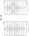
- the communication/control circuit 120 and the communication/control circuit 220 may each be implemented and operated with a communication architecture as shown in FIG. 4B .
- FIG. 4B is a diagram illustrating an example of a Bluetooth communication architecture to which an embodiment according to the present disclosure may be applied.
- FIG. 4B shows an example of a protocol stack of Bluetooth basic rate (BR)/enhanced data rate (EDR) supporting GATT, and (b) shows an example of Bluetooth low energy (BLE) protocol stack.
- BR Bluetooth basic rate
- EDR enhanced data rate
- BLE Bluetooth low energy
- the Bluetooth BR/EDR protocol stack may include an upper control stack 460 and a lower host stack 470 based on a host controller interface (HCl) 18.
- HCl host controller interface
- the host stack (or host module) 470 refers to hardware for transmitting or receiving a Bluetooth packet to or from a wireless transmission/reception module which receives a Bluetooth signal of 2.4 GHz, and the controller stack 460 is connected to the Bluetooth module to control the Bluetooth module and perform an operation.
- the host stack 470 may include a BR/EDR PHY layer 12, a BR/EDR baseband layer 14, and a link manager layer 16.
- the BR/EDR PHY layer 12 is a layer that transmits and receives a 2.4 GHz radio signal, and in the case of using Gaussian frequency shift keying (GFSK) modulation, the BR/EDR PHY layer 12 may transmit data by hopping 79 RF channels.
- GFSK Gaussian frequency shift keying
- the BR/EDR baseband layer 14 serves to transmit a digital signal, selects a channel sequence for hopping 1400 times per second, and transmits a time slot with a length of 625 us for each channel.
- the link manager layer 16 controls an overall operation (link setup, control, security) of Bluetooth connection by utilizing a link manager protocol (LMP).
- LMP link manager protocol
- the link manager layer 16 may perform the following functions.
- the host controller interface layer 18 provides an interface between a host module and a controller module so that a host provides commands and data to the controller and the controller provides events and data to the host.
- the host stack (or host module, 470) includes a logical link control and adaptation protocol (L2CAP) 21, an attribute protocol 22, a generic attribute profile (GATT) 23, a generic access profile (GAP) 24, and a BR/EDR profile 25.
- L2CAP logical link control and adaptation protocol
- GATT generic attribute profile
- GAP generic access profile
- BR/EDR profile 25 BR/EDR profile
- the logical link control and adaptation protocol (L2CAP) 21 may provide one bidirectional channel for transmitting data to a specific protocol or profile.
- the L2CAP 21 may multiplex various protocols, profiles, etc., provided from upper Bluetooth.
- L2CAP of Bluetooth BR/EDR uses dynamic channels, supports protocol service multiplexer, retransmission, streaming mode, and provides segmentation and reassembly, per-channel flow control, and error control.
- the Bluetooth LE protocol stack includes a controller stack 480 operable to process a wireless device interface important in timing and a host stack 490 operable to process high level data.
- the L2CAP 41 may be operable to multiplex data between higher layer protocols, segment and reassemble packages, and manage multicast data transmission.
- a basic channel/enhanced data rate uses a dynamic channel and supports protocol service multiplexer, retransmission, streaming mode, and the like.
- the security manager (SM) 42 is a protocol for authenticating devices and providing key distribution.
- the GATT 44 and the ATT 43 may use features in order to describe status and services of a device and describe how the features are related and used.
- the controller stack may perform control to reduce the number of transmitted requests to reduce power consumption.
- An advertising device or scanning device may perform the device filtering procedure to limit devices for receiving an advertising packet, a scan request or a connection request.
- the advertising device refers to a device transmitting an advertising event, that is, a device performing an advertisement and is also termed an advertiser.
- the advertising device performs an advertising procedure to perform undirected broadcast to devices within a region.
- directed advertising may make an supplemental information request or a connection request by scanning advertising for only a device designated as a reception device.
- the advertising procedure is used to establish a Bluetooth connection with an initiating device nearby.
- Broadcast user data sent as part of advertising packets are dynamic data, while the scan response data is generally static data.
- the scanning device transmits a scan request to an advertising device through an advertising physical channel in order to request additional data from the advertising device.
- the advertising device transmits a scan response as a response with respect to the scan request, by including additional user data which has requested by the scanning device through an advertising physical channel.
- the scanning procedure may be used while being connected to other BLE device in the BLE piconet.
- the scanning device When the scanning device transmits a connection request to the advertising device, the scanning device stops the initiator mode scanning for additional broadcast and enters the connected mode.
- Bluetooth devices Devices available for Bluetooth communication (hereinafter, referred to as “Bluetooth devices”) perform an advertising procedure and a scanning procedure in order to discover devices located nearby or in order to be discovered by other devices within a given area.
- the discovering procedure is performed asymmetrically.
- a Bluetooth device intending to discover other device nearby is termed a discovering device, and listens to discover devices advertising an advertising event that may be scanned.
- a Bluetooth device which may be discovered by other device and available to be used is termed a discoverable device and positively broadcasts an advertising event such that it may be scanned by other device through an advertising (broadcast) physical channel.
- Both the discovering device and the discoverable device may have already been connected with other Bluetooth devices in a piconet.
- a connecting procedure is asymmetrical, and requests that, while a specific Bluetooth device is performing an advertising procedure, another Bluetooth device should perform a scanning procedure.
- an advertising procedure may be aimed, and as a result, only one device may response to the advertising.
- a connecting request may be transmitted to the advertising device through an advertising (broadcast) physical channel to initiate connection.
- a link layer enters an advertising state according to an instruction from a host (stack). In a case in which the LL is in the advertising state, the LL transmits an advertising packet data unit (PDU) in advertising events.
- PDU packet data unit
- Each of the advertising events include at least one advertising PDU, and the advertising PDU is transmitted through an advertising channel index in use. After the advertising PDU is transmitted through an advertising channel index in use, the advertising event may be terminated, or in a case in which the advertising device may need to secure a space for performing other function, the advertising event may be terminated earlier.
- the LL enters the scanning state according to an instruction from the host (stack). In the scanning state, the LL listens to advertising channel indices.
- the scanning state includes two types: passive scanning and active scanning. Each of the scanning types is determined by the host.
- Time for performing scanning or an advertising channel index are not defined.
- a scan interval is defined as an interval between start points of two continuous scan windows.
- the LL When there is no collision in scheduling, the LL should listen in order to complete all the scan intervals of the scan window as instructed by the host. In each scan window, the LL should scan other advertising channel index. The LL uses every available advertising channel index.
- the LL In the passive scanning, the LL only receives packets and cannot transmit any packet.
- the LL performs listening in order to be relied on an advertising PDU type for requesting advertising PDUs and advertising device-related supplemental information from the advertising device.
- the LL enters the initiating state according to an instruction from the host (stack).
- the LL When the LL is in the initiating state, the LL performs listening on advertising channel indices.
- the LL listens to an advertising channel index during the scan window interval.
- the LL When the device performing a connection state, that is, when the initiating device transmits a CONNECT_REQ PDU to the advertising device or when the advertising device receives a CONNECT_REQ PDU from the initiating device, the LL enters a connection state.
- connection is generated after the LL enters the connection state. However, it is not necessary to consider that the connection should be established at a point in time at which the LL enters the connection state. The only difference between a newly generated connection and an already established connection is a LL connection supervision timeout value.
- An LL serving as a master is termed a master, and an LL serving as a slave is termed a slave.
- the master adjusts a timing of a connecting event, and the connecting event refers to a point in time at which the master and the slave are synchronized.
- BLE devices use packets defined as follows.
- the LL has only one packet format used for both an advertising channel packet and a data channel packet.
- Each packet includes four fields of a preamble, an access address, a PDU, and a CRC.
- the PDU When one packet is transmitted in an advertising physical channel, the PDU may be an advertising channel PDU, and when one packet is transmitted in a data physical channel, the PDU may be a data channel PDU.
- An advertising channel PDU has a 16-bit header and payload having various sizes.
- a PDU type field of the advertising channel PDU included in the heater indicates PDU types defined in Table 3 below.
- advertising channel PDU types are termed advertising PDUs and used in a specific event.
- the PDUs are transmitted from the LL in an advertising state, and received by the LL in a scanning state or in an initiating state.
- the following advertising channel DPU types are termed scanning PDUs and are used in a state described hereinafter.
- SCAN_REQ Transmitted by the LL in a scanning state and received by the LL in an advertising state.
- SCAN_RSP Transmitted by the LL in the advertising state and received by the LL in the scanning state.
- the following advertising channel PDU type is termed an initiating PDU.
- CONNECT_REQ Transmitted by the LL in the initiating state and received by the LL in the advertising state.
- the data channel PDU may include a message integrity check (MIC) field having a 16-bit header and payload having various sizes.
- MIC message integrity check
- the load (455) may correspond to a battery.
- the battery may store energy by using the power that is being outputted from the power pick-up unit (210). Meanwhile, the battery is not mandatorily required to be included in the mobile device (450).
- the battery may be provided as a detachable external feature.
- the wireless power receiver may include an operating means that may execute diverse functions of the electronic device instead of the battery.
- the mobile device (450) is illustrated to be included in the wireless power receiver (200) and the base station (400) is illustrated to be included in the wireless power transmitter (100), in a broader meaning, the wireless power receiver (200) may be identified (or regarded) as the mobile device (450), and the wireless power transmitter (100) may be identified (or regarded) as the base station (400).
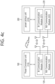
- the wireless power transmitter 100 including the communication/control circuit 120 and the wireless power receiver 200 including the communication/control circuit 220 may be represented by a simplified block diagram as shown in FIG. 4C .
- FIG. 4C is a block diagram illustrating a wireless power transfer system using BLE communication according to an example.
- the wireless power transmitter 100 includes a power conversion circuit 110 and a communication/control circuit 120.
- the communication/control circuit 120 includes an in-band communication module 121 and a BLE communication module 122.
- the wireless power receiver 200 includes a power pickup circuit 210 and a communication/control circuit 220.
- the communication/control circuit 220 includes an in-band communication module 221 and a BLE communication module 222.
- the BLE communication modules 122 and 222 perform the architecture and operation according to FIG. 4B .
- the BLE communication modules 122 and 222 may be used to establish a connection between the wireless power transmitter 100 and the wireless power receiver 200 and exchange control information and packets necessary for wireless power transfer.
- the communication/control circuit 120 may be configured to operate a profile for wireless charging.
- the profile for wireless charging may be GATT using BLE transmission.
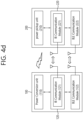
- FIG. 4D is a block diagram illustrating a wireless power transfer system using BLE communication according to another example.
- the communication/control circuits 120 and 220 respectively include only in-band communication modules 121 and 221, and the BLE communication modules 122 and 222 may be provided to be separated from the communication/control circuits 120 and 220.
- the coil or coil unit includes a coil and at least one device being approximate to the coil, and the coil or coil unit may also be referred to as a coil assembly, a coil cell, or a cell.
- FIG. 5 is a state transition diagram for describing a wireless power transfer procedure.
- the power transfer (or transfer) from the wireless power transmitter to the wireless power receiver may be broadly divided into a selection phase (510), a ping phase (520), an identification and configuration phase (530), a negotiation phase (540), a calibration phase (550), a power transfer phase (560), and a renegotiation phase (570).
- the selection phase (510) may include a shifting phase (or step) - reference numerals S502, S504, S508, S510, and S512.
- the specific error or specific event will be specified in the following description.
- the wireless power transmitter may monitor whether or not an object exists on an interface surface. If the wireless power transmitter detects that an object is placed on the interface surface, the process step may be shifted to the ping phase (520).
- the wireless power transmitter may transmit an analog ping having a power signal(or a pulse) corresponding to an extremely short duration, and may detect whether or not an object exists within an active area of the interface surface based on a current change in the transmitting coil or the primary coil.
- the wireless power transmitter may measure a quality factor of a wireless power resonance circuit (e.g., power transfer coil and/or resonance capacitor).
- a wireless power resonance circuit e.g., power transfer coil and/or resonance capacitor.
- the wireless power transmitter may measure the quality factor in order to determine whether or not a foreign object exists in the charging area along with the wireless power receiver.
- inductance and/or components of the series resistance may be reduced due to a change in the environment, and, due to such decrease, a value of the quality factor may also be decreased.
- the wireless power transmitter may receive from the wireless power receiver a reference quality factor value, which is measured in advance in a state where no foreign object is placed within the charging area.
- the wireless power transmitter may determine the presence or absence of a foreign object by comparing the measured quality factor value with the reference quality factor value, which is received during the negotiation phase (540).
- the wireless power receiver may have a low reference quality factor value - in case a foreign object exists, since the difference between the reference quality factor value and the measured quality factor value is small (or insignificant), a problem may occur in that the presence of the foreign object cannot be easily determined. Accordingly, in this case, other determination factors should be further considered, or the present or absence of a foreign object should be determined by using another method.
- the wireless power transmitter may measure the quality factor value within a specific frequency area (e.g., operation frequency area).
- a specific frequency area e.g., operation frequency area
- inductance and/or components of the series resistance may be reduced due to a change in the environment, and, due to such decrease, the resonance frequency of the coil of the wireless power transmitter may be changed (or shifted). More specifically, a quality factor peak frequency that corresponds to a frequency in which a maximum quality factor value is measured within the operation frequency band may be moved (or shifted).
- the wireless power transmitter In the ping phase (520), if the wireless power transmitter detects the presence of an object, the transmitter activates (or Wakes up) a receiver and transmits a digital ping for identifying whether or not the detected object corresponds to the wireless power receiver.
- the wireless power transmitter fails to receive a response signal for the digital ping - e.g., a signal intensity packet - from the receiver, the process may be shifted back to the selection phase (510).
- the wireless power transmitter receives a signal indicating the completion of the power transfer-e.g., charging complete packet - from the receiver, the process may be shifted back to the selection phase (510).
- the wireless power transmitter may shift to the identification and configuration phase (530) for identifying the receiver and for collecting configuration and status information.
- the wireless power transmitter may shift to the selection phase (510).
- the wireless power transmitter may confirm (or verify) whether or not its entry to the negotiation phase (540) is needed based on a Negotiation field value of the configuration packet, which is received during the identification and configuration phase (530). Based on the verified result, in case a negotiation is needed, the wireless power transmitter enters the negotiation phase (540) and may then perform a predetermined FOD detection procedure. Conversely, in case a negotiation is not needed, the wireless power transmitter may immediately enter the power transfer phase (560).
- the wireless power transmitter may receive a Foreign Object Detection (FOD) status packet that includes a reference quality factor value.
- the wireless power transmitter may receive an FOD status packet that includes a reference peak frequency value.
- the wireless power transmitter may receive a status packet that includes a reference quality factor value and a reference peak frequency value.
- the wireless power transmitter may determine a quality coefficient threshold value for FO detection based on the reference quality factor value.
- the wireless power transmitter may determine a peak frequency threshold value for FO detection based on the reference peak frequency value.
- the wireless power transmitter may detect the presence or absence of an FO in the charging area by using the determined quality coefficient threshold value for FO detection and the currently measured quality factor value (i.e., the quality factor value that was measured before the ping phase), and, then, the wireless power transmitter may control the transmitted power in accordance with the FO detection result. For example, in case the FO is detected, the power transfer may be stopped.
- the present disclosure will not be limited only to this.
- the wireless power transmitter may detect the presence or absence of an FO in the charging area by using the determined peak frequency threshold value for FO detection and the currently measured peak frequency value (i.e., the peak frequency value that was measured before the ping phase), and, then, the wireless power transmitter may control the transmitted power in accordance with the FO detection result. For example, in case the FO is detected, the power transfer may be stopped.
- the present disclosure will not be limited only to this.
- the wireless power transmitter may return to the selection phase (510). Conversely, in case the FO is not detected, the wireless power transmitter may proceed to the calibration phase (550) and may, then, enter the power transfer phase (560). More specifically, in case the FO is not detected, the wireless power transmitter may determine the intensity of the received power that is received by the receiving end during the calibration phase (550) and may measure power loss in the receiving end and the transmitting end in order to determine the intensity of the power that is transmitted from the transmitting end. In other words, during the calibration phase (550), the wireless power transmitter may estimate the power loss based on a difference between the transmitted power of the transmitting end and the received power of the receiving end.
- the wireless power transmitter according to the exemplary embodiment of the present disclosure may calibrate the threshold value for the FOD detection by applying the estimated power loss.
- the wireless power transmitter may shift to the selection phase (510).
- the wireless power transmitter may shift to the renegotiation phase (570). At this point, if the renegotiation is successfully completed, the wireless power transmitter may return to the power transfer phase (560).
- the above-described power transfer contract may be configured based on the status and characteristic information of the wireless power transmitter and receiver.
- the wireless power transmitter status information may include information on a maximum amount of transmittable power, information on a maximum number of receivers that may be accommodated, and so on.
- the receiver status information may include information on the required power, and so on.
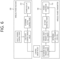
- FIG. 6 shows a power control method according to an exemplary embodiment of the present disclosure.
- the wireless power transmitter (100) and the wireless power receiver (200) may control the amount (or size) of the power that is being transferred.
- the wireless power transmitter and the wireless power receiver operate at a specific control point.
- the control point indicates a combination of the voltage and the electric current that are provided from the output of the wireless power receiver, when the power transfer is performed.
- the wireless power receiver selects a desired control point, a desired output current/voltage, a temperature at a specific location of the mobile device, and so on, and additionally determines an actual control point at which the receiver is currently operating.
- the wireless power receiver calculates a control error value by using the desired control point and the actual control point, and, then, the wireless power receiver may transmit the calculated control error value to the wireless power transmitter as a control error packet.
- the wireless power transmitter may configure/control a new operating point - amplitude, frequency, and duty cycle - by using the received control error packet, so as to control the power transfer. Therefore, the control error packet may be transmitted/received at a constant time interval during the power transfer phase, and, according to the exemplary embodiment, in case the wireless power receiver attempts to reduce the electric current of the wireless power transmitter, the wireless power receiver may transmit the control error packet by setting the control error value to a negative number. And, in case the wireless power receiver intends to increase the electric current of the wireless power transmitter, the wireless power receiver transmit the control error packet by setting the control error value to a positive number. During the induction mode, by transmitting the control error packet to the wireless power transmitter as described above, the wireless power receiver may control the power transfer.
- the device may be operated by using a method that is different from the induction mode.
- one wireless power transmitter should be capable of serving a plurality of wireless power receivers at the same time.
- a method of controlling the amount of power that is being received by having the wireless power transmitter commonly transfer (or transmit) the basic power and by having the wireless power receiver control its own resonance frequency. Nevertheless, even during the operation of the resonance mode, the method described above in FIG. 6 will not be completely excluded. And, additional control of the transmitted power may be performed by using the method of FIG. 6 .
- FIG. 7 is a block diagram of a wireless power transmitter according to another exemplary embodiment of the present disclosure. This may belong to a wireless power transfer system that is being operated in the magnetic resonance mode or the shared mode.
- the shared mode may refer to a mode performing a several-for-one (or one-to-many) communication and charging between the wireless power transmitter and the wireless power receiver.
- the shared mode may be implemented as a magnetic induction method or a resonance method.
- the wireless power transmitter (700) may include at least one of a cover (720) covering a coil assembly, a power adapter (730) supplying power to the power transmitter (740), a power transmitter (740) transmitting wireless power, and a user interface (750) providing information related to power transfer processing and other related information.
- the user interface (750) may be optionally included or may be included as another user interface (750) of the wireless power transmitter (700).
- the power transmitter (740) includes a coil assembly (760), an impedance matching circuit (770), an inverter (780), a communication unit (790), and a control unit (710).
- the coil assembly (760) includes at least one primary coil generating a magnetic field. And, the coil assembly (760) may also be referred to as a coil cell.
- the impedance matching circuit (770) may provide impedance matching between the inverter and the primary coil(s).
- the impedance matching circuit (770) may generate resonance from a suitable frequency that boosts the electric current of the primary coil(s).
- the impedance matching circuit may additionally include a multiplex that routes signals from the inverter to a subset of the primary coils.
- the impedance matching circuit may also be referred to as a tank circuit.
- the impedance matching circuit (770) may include a capacitor, an inductor, and a switching device that switches the connection between the capacitor and the inductor.
- the impedance matching may be performed by detecting a reflective wave of the wireless power that is being transferred (or transmitted) through the coil assembly (760) and by switching the switching device based on the detected reflective wave, thereby adjusting the connection status of the capacitor or the inductor or adjusting the capacitance of the capacitor or adjusting the inductance of the inductor. In some cases, the impedance matching may be carried out even though the impedance matching circuit (770) is omitted.
- This specification also includes an exemplary embodiment of the wireless power transmitter (700), wherein the impedance matching circuit (770) is omitted.
- the inverter (780) may convert a DC input to an AC signal.
- the inverter (780) may be operated as a half-bridge inverter or a full-bridge inverter in order to generate a pulse wave and a duty cycle of an adjustable frequency. Additionally, the inverter may include a plurality of stages in order to adjust input voltage levels.
- the communication unit (790) may perform communication with the power receiver.
- the power receiver performs load modulation in order to communicate requests and information corresponding to the power transmitter. Therefore, the power transmitter (740) may use the communication unit (790) so as to monitor the amplitude and/or phase of the electric current and/or voltage of the primary coil in order to demodulate the data being transmitted from the power receiver.
- the power transmitter (740) may control the output power to that the data may be transferred through the communication unit (790) by using a Frequency Shift Keying (FSK) method, and so on.
- FSK Frequency Shift Keying
- the control unit (710) may control communication and power transfer (or delivery) of the power transmitter (740).
- the control unit (710) may control the power transfer by adjusting the above-described operating point.
- the operating point may be determined by, for example, at least any one of the operation frequency, the duty cycle, and the input voltage.
- the communication unit (790) and the control unit (710) may each be provided as a separate unit/device/chipset or may be collectively provided as one unit/device/chipset.
- FIG. 8 shows a wireless power receiver according to another exemplary embodiment of the present disclosure. This may belong to a wireless power transfer system that is being operated in the magnetic resonance mode or the shared mode.
- the wireless power receiver (800) may include at least one of a user interface (820) providing information related to power transfer processing and other related information, a power receiver (830) receiving wireless power, a load circuit (840), and a base (850) supporting and covering the coil assembly.
- a user interface (820) may be optionally included or may be included as another user interface (820) of the wireless power receiver (800).
- the power receiver (830) includes a power converter (860), an impedance matching circuit (870), a coil assembly (880), a communication unit (890), and a control unit (810).
- the power converter (860) may convert the AC power that is received from the secondary coil to a voltage and electric current that are suitable for the load circuit.
- the power converter (860) may include a rectifier.
- the rectifier may rectify the received wireless power and may convert the power from an alternating current (AC) to a direct current (DC).
- the rectifier may convert the alternating current to the direct current by using a diode or a transistor, and, then, the rectifier may smooth the converted current by using the capacitor and resistance.
- a full-wave rectifier, a half-wave rectifier, a voltage multiplier, and so on, that are implemented as a bridge circuit may be used as the rectifier.
- the power converter may adapt a reflected impedance of the power receiver.
- the impedance matching circuit (870) may provide impedance matching between a combination of the power converter (860) and the load circuit (840) and the secondary coil. According to an exemplary embodiment, the impedance matching circuit may generate a resonance of approximately 100kHz, which may reinforce the power transfer.
- the impedance matching circuit (870) may include a capacitor, an inductor, and a switching device that switches the combination of the capacitor and the inductor. The impedance matching may be performed by controlling the switching device of the circuit that configured the impedance matching circuit (870) based on the voltage value, electric current value, power value, frequency value, and so on, of the wireless power that is being received. In some cases, the impedance matching may be carried out even though the impedance matching circuit (870) is omitted.
- This specification also includes an exemplary embodiment of the wireless power receiver (200), wherein the impedance matching circuit (870) is omitted.
- the coil assembly (880) includes at least one secondary coil, and, optionally, the coil assembly (880) may further include an element shielding the metallic part of the receiver from the magnetic field.
- the communication unit (890) may perform load modulation in order to communicate requests and other information to the power transmitter.
- the power receiver (830) may perform switching of the resistance or capacitor so as to change the reflected impedance.
- the control unit (810) may control the received power. For this, the control unit (810) may determine/calculate a difference between an actual operating point and a target operating point of the power receiver (830). Thereafter, by performing a request for adjusting the reflected impedance of the power transmitter and/or for adjusting an operating point of the power transmitter, the difference between the actual operating point and the target operating point may be adjusted/reduced. In case of minimizing this difference, an optimal power reception may be performed.
- the communication unit (890) and the control unit (810) may each be provided as a separate device/chipset or may be collectively provided as one device/chipset.
- FIG. 9 shows a communication frame structure according to an exemplary embodiment of the present disclosure. This may correspond to a communication frame structure in a shared mode.
- the slotted frame and the free format frame may be referred to other diverse terms by anyone skilled in the art.
- the slotted frame may be alternatively referred to as a channel frame
- the free format frame may be alternatively referred to as a message frame.
- the additional sync pattern corresponds to a sync pattern that is different from the sync pattern that indicates the starting point of the above-described frame. More specifically, the additional sync pattern does not indicate the starting point of the frame but may indicate information related to the neighboring (or adjacent) slots (i.e., two consecutive slots positioned on both sides of the sync pattern).
- the nine slots and the sync patterns being provided before each of the nine slots may have the same time interval.
- the nine slots may have a time interval of 50ms.
- the nine sync patterns may have a time length of 50ms.
- the free format frame may not have a specific format apart from the sync pattern indicating the starting point of the frame and the measurement slot. More specifically, the free format frame is configured to perform a function that is different from that of the slotted frame. For example, the free format frame may be used to perform a function of performing communication of long data packets (e.g., additional owner information packets) between the wireless power transmitter and the wireless power receiver, or, in case of a wireless power transmitter being configured of multiple coils, to perform a function of selecting any one of the coils.
- long data packets e.g., additional owner information packets
- the sync pattern may be configured of a preamble, a start bit, a response field, a type field, an info field, and a parity bit.
- the start bit is illustrated as ZERO.
- the ZERO is equal to 0
- this may indicate that the corresponding slot is a slot sync that is positioned in-between slots.
- this may indicate that the corresponding sync pattern is a frame sync being located in-between frames.
- the information field may indicate a state of a next slot, which is positioned after the sync pattern. More specifically, in case the next slot corresponds to a slot that is allocated (or assigned) to a specific wireless power receiver, the information field is given a value of '00'. In case the next slot corresponds to a slot that is locked, so as to be temporarily used by the specific wireless power receiver, the information field is given a value of ⁇ 01'. Alternatively, in case the next slot corresponds to a slot that may be freely used by a random wireless power receiver, the information field is given a value of '10'.
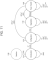
- FIG. 11 shows operation statuses of a wireless power transmitter and a wireless power receiver in a shared mode according to an exemplary embodiment of the present disclosure.
- the wireless power receiver operating in the shared mode may be operated in any one of a selection phase (1100), an introduction phase (1110), a configuration phase (1120), a negotiation phase (1130), and a power transfer phase (1140).
- the wireless power receiver that has received the wireless power signal may enter the selection phase (1100).
- the wireless power receiver that has entered the selection phase (1100) may detect the presence or absence of an FSK signal within the wireless power signal.
- the wireless power receiver may perform communication by using any one of an exclusive mode and a shared mode in accordance with the presence or absence of the FSK signal.
- the wireless power receiver may enter the introduction phase (1110).
- the wireless power receiver may transmit a control information (CI) packet to the wireless power transmitter in order to transmit the control information packet during the configuration phase, the negotiation phase, and the power transfer phase.
- the control information packet may have a header and information related to control.
- the header may correspond to 0X53.
- the wireless power receiver performs an attempt to request a free slot for transmitting the control information (CI) packet during the following configuration phase, negotiation phase, and power transfer phase. At this point, the wireless power receiver selects a free slot and transmits an initial CI packet. If the wireless power transmitter transmits an ACK as a response to the corresponding CI packet, the wireless power receiver enters the configuration phase. If the wireless power transmitter transmits a NAK as a response to the corresponding CI packet, this indicates that another wireless power receiver is performing communication through the configuration and negotiation phase. In this case, the wireless power receiver re-attempts to perform a request for a free slot.
- CI control information
- the wireless power receiver may determine the position of a private slot within the frame by counting the remaining sync slots up to the initial frame sync. In all of the subsequent slot-based frames, the wireless power receiver transmits the CI packet through the corresponding slot.
- the wireless power transmitter authorizes the entry of the wireless power receiver to the configuration phase
- the wireless power transmitter provides a locked slot series for the exclusive usage of the wireless power receiver. This may ensure the wireless power receiver to proceed to the configuration phase without any collision.
- the wireless power receiver transmits sequences of data packets, such as two identification data packets (IDHI and IDLO), by using the locked slots.
- IDHI and IDLO identification data packets
- the wireless power receiver enters the negotiation phase.
- the wireless power transmitter continues to provide the locked slots for the exclusive usage of the wireless power receiver. This may ensure the wireless power receiver to proceed to the negotiation phase without any collision.
- the wireless power receiver transmits one or more negotiation data packets by using the corresponding locked slot, and the transmitted negotiation data packet(s) may be mixed with the private data packets.
- the corresponding sequence is ended (or completed) along with a specific request (SRQ) packet.
- SRQ specific request
- control may be needed in order to prevent an overvoltage state.
- the wireless power transfer system using in-band communication may use USB-C authentication.
- the authentication may include an authentication of the wireless power transmitter that is performed by the wireless power receiver (i.e., PTx Authentication by PRx), and an authentication of the wireless power receiver that is performed by the wireless power transmitter (PRx Authentication by PTx).
- FIG. 12 is a block diagram showing a wireless charging certificate format according to an exemplary embodiment of the present disclosure.
- the wireless charging certificate format includes a Certificate Structure Version, a reserved field, PTx and leaf indicators, a certificate type, a signature offset, a serial number, an issuer ID, a subject ID, a public key, and a signature.
- the certificate type may, for example, by assigned with 3 bits, and the certificate type may indicate that the corresponding certificate is any one of a root certificate, an intermediate certificate, and a last certificate. And, the certificate type may also indicate that the corresponding certificate is a certificate relating to a wireless power transmitter or a wireless power receiver or all type.
- the certificate type is 3 bits and may indicate information on a root certificate, manufacturer/secondary certificate, and product unit certificate (for the power transmitter). More specifically, a certificate type '001'b may indicate the root certificate, and ⁇ 010'b may indicate an intermediate certificate (manufacturer/secondary Certificate), and '111'b may indicate a product unit certificate for the power transmitter, which is a final certificate.
- the wireless power transmitter may notify (or announce) whether or not it supports the authentication function to the wireless power receiver by using a capability packet (in case of an authentication of the wireless power transmitter by the wireless power receiver (authentication of PTx by PRx)).
- the wireless power receiver may notify (or announce) whether or not it supports the authentication function to the wireless power transmitter by using a capability packet (in case of an authentication of the wireless power receiver by the wireless power transmitter (authentication of PRx by PTx)).
- a structure of indication information (a capability packet and a configuration packet) related to whether or not a device supports the authentication function will be disclosed and described in detail.
- FIG. 13 is a capability packet structure of a wireless power transmitter according to an exemplary embodiment of the present disclosure.
- a capability packet having a respective header value of 0X31 is assigned with 3 bytes.
- a first byte (B0) includes a power class and a guaranteed power value
- a second byte (B1) includes a reserved field and a potential power field
- a third byte (B2) includes an Authentication Initiator (AI), an Authentication Responder (AR), a reserved field, a WPID, and a Not Res Sens field.
- the Authentication Initiator (AI) is assigned with 1 bit.
- the Authentication Responder (AR) is also assigned with 1 bit.
- the value is equal to '1b', this may indicate that the corresponding wireless power transmitter may operate as the authentication responder.
- FIG. 14 is a configuration packet structure of a wireless power receiver according to an exemplary embodiment of the present disclosure.
- a capability packet having a respective header value of 0X51 is assigned with 5 bytes.
- a first byte (B0) includes a power class and a maximum power value
- a second byte (B1) includes an AI
- an AR a reserved field
- a third byte (B2) includes a Prop, a reserved field, a ZERO field, and a Count field
- a fourth value (B3) includes a Window size and a window offset
- a fifth byte (B4) includes a Neg field, a polarity field, a Depth field, an authentication field (Auth), and a reserved field. More specifically, the Authentication Initiator (AI) is assigned with 1 bit.
- the Authentication Responder is also assigned with 1 bit.
- the value is equal to '1b', this may indicate that the corresponding wireless power receiver may operate as the authentication responder.
- a message that is used during the authentication procedure is referred to as an authentication message.
- the authentication message is used for carrying information related to authentication.
- One type corresponds to an authentication request, and another type corresponds to an authentication response.
- the authentication request is transmitted by the authentication initiator, and the authentication response is transmitted by the authentication responder.
- Both the wireless power transmitter and the wireless power receiver may be the authentication initiator or the authentication responder. For example, in case the wireless power transmitter is the authentication initiator, the wireless power receiver becomes the authentication responder. And, in case the wireless power receiver is the authentication initiator, the wireless power transmitter becomes the authentication responder.
- An authentication request message includes a GET_DIGESTS (i.e., 4 bytes), a GET_CERTIFICATE (i.e., 8 bytes), and a CHALLENGE (i.e., 36 bytes).
- GET_DIGESTS i.e., 4 bytes
- GET_CERTIFICATE i.e., 8 bytes
- CHALLENGE i.e., 36 bytes
- DIGESTS i.e., 4+32 bytes
- CHALLENGE_AUTH i.e., 168 bytes
- ERROR i.e., 4 bytes
- An authentication message may be referred to as an authentication packet and may also be referred to as authentication data or authentication control information. Additionally, messages, such as GET_DIGEST, DIGESTS, and so on, may also be referred to as a GET_DIGEST packet, a DIGEST packet, and so on.
- FIG. 15 shows an application-level data stream between a wireless power transmitter and a receiver according to an example.
- a data stream may include an auxiliary data control (ADC) data packet and/or an auxiliary data transport (ADT) data packet.
- ADC auxiliary data control
- ADT auxiliary data transport
- the ADC data packet is used to open a data stream.
- the ADC data packet may indicate the type of a message included in a stream and the number of data bytes. Meanwhile, the ADT data packet is sequences of data including an actual message.
- An ADC/end data packet is used to indicate the end of the stream. For example, the maximum number of data bytes in a data transport stream may be limited to 2047.
- ACK or NAC is used to indicate whether the ADC data packet and the ADT data packet are normally received.
- Control information necessary for wireless charging such as a control error packet (CE) or DSR may be transmitted between transmission timings of the ADC data packet and the ADT data packet.
- CE control error packet
- DSR may be transmitted between transmission timings of the ADC data packet and the ADT data packet.
- authentication related information or other application level information may be transmitted and received between the wireless power transmitter and the wireless power receiver.
- a wireless power transmitter transmits wireless power to a wireless power receiver using a magnetic field
- a part of magnetic field may be absorbed to the foreign object. That is, a part of the wireless power transmitted from the wireless power transmitter is supplied to the foreign object and the rest is supplied to the wireless power receiver. From the viewpoint of the efficiency of power transfer, loss of transmitted power occurs as much as power or energy absorbed by the foreign object.
- P loss power loss
- the wireless power transmitter may detect how much power loss occurs through the foreign object.
- Such a foreign object detection method may be referred to as a foreign object detection method based on power loss.
- the power lost by the foreign object may be defined as a value obtained by subtracting the power (P received ) actually received by the wireless power receiver from the power (P transmitted ) transmitted from the wireless power transmitter. From the standpoint of the wireless power transmitter, the wireless power transmitter knows the power (P transmitted ) transmitted by itself, and thus, the lost power may be obtained if only the power actually received by the wireless power receiver is known. To this end, the wireless power receiver is configured to notify the wireless power transmitter of the received power by transmitting a received power packet (RPP) to the wireless power transmitter.
- RPP received power packet
- the wireless power transmitter and the wireless power receiver include various circuit components therein and configure devices independent of each other.
- the wireless power transmitter and the wireless power receiver constitute one wireless power transfer system.
- the amount of power (transmitted power) transmitted by the wireless power transmitter and the amount of power (received power) received by the wireless power receiver are uniquely determined by the power transfer characteristics.
- power transfer characteristics may be considered as a ratio or function of transmitted power and received power. Therefore, if the wireless power transmitter knows the power transfer characteristics in advance, the wireless power transmitter may be able to predict how much of the power transmitted by the wireless power transmitter will be received by the wireless power receiver.
- the foreign object detection method based on power loss may determine that a foreign object exists in the above case. As described above, power loss used for the determination of a foreign object is also determined based on the power transfer characteristics, and therefore, power transfer characteristics need to be properly recognized to increase reliability of foreign object detection.
- the power transfer characteristic is dependent on an environment in which wireless power is transmitted or a unique characteristic of a device transmitting wireless power.
- the wireless power transmitter and the wireless power receiver may generally use power calibration at the start of wireless power transfer to determine the power transfer characteristics in a certain currently given wireless charging environment. When the power transfer characteristics are identified or set by power calibration, foreign object detection is performed accordingly.
- the power transfer characteristics may also be dependent on a change in load or a degree of magnetic coupling. For example, when the wireless power receiver uses multiple load steps or variable load (or load increase) or when the degree of a change in magnetic coupling due to a change in position between the wireless power transmitter and the wireless power receiver, at least a part of the power transfer characteristics may be changed. If at least a part of the power transfer characteristic changes, at least a part of power calibration set according to the previous power transfer characteristic becomes invalid. In addition, power loss and foreign object detection according to the at least part of the set power calibration are no longer valid. Therefore, it is necessary to additionally calibrate power for the changed power transfer characteristics.
- FIG. 16 is a flowchart illustrating a method of performing power calibration and foreign object detection according to an example out of the scope of the invention.
- the received power packet refers to additional information for constructing a power calibration curve and may indicate a power value received by the wireless power receiver (hereinafter, referred to as a connected-load calibration value, Prec_connected) when the wireless power receiver is generally in a connected-load condition.
- the light load condition may refer to a condition in which a load (e.g., a battery) is not electrically connected to the wireless power receiver
- the connected-load condition may refer to a condition in which a load is connected to the wireless power receiver.
- the wireless power receiver receives and measures a first connected-load transmitted power (Ptr_connected (1)) from the wireless power transmitter under the first connected load condition, and then transmits a second received power packet (i.e., RP/2) indicating the first connected-load calibration value (Prec_connected(1)) to the wireless power transmitter (S1405).
- a first connected-load transmitted power Ptr_connected (1)
- RP/2 a second received power packet
- the wireless power transmitter may include a step of performing FOD through Q measurement and new power calibration again.
- the new power calibration in this case may include the power calibration described in FIGS. 16 to 21 .
- the new power calibration of the wireless power transmitter may include a power calibration operation of the wireless power transmitter according to FIGS. 16 to 21
- the new power calibration of the wireless power receiver may include a power calibration operation of the wireless power receiver according to FIGS. 16 to 21 . Accordingly, additional power calibration according to the change in coupling is completed, and power calibration data such as the calibrated transmitted power value and/or a calibrated received power value according to the new power calibration may be derived.
- FIG. 23 is a flowchart illustrating a power calibration method based on a change in coupling according to another embodiment.
- the re-ping packet may have a packet structure including reserved bits of 2 bits and a field (e.g., 6 bits) indicating re-ping time information.
- the re-ping time information is a natural number from 1 to 64 and is used to calculate the re-ping time Tre-ping.
- the number of bits included in the field indicating the reserved bit and the re-ping time may be variously modified.
- the wireless power transmitter in the embodiments according to FIG. 23 corresponds to the wireless power transmission device, the wireless power transmitter, or power transmission part disclosed in FIGS. 1 to 15 . Accordingly, the operation of the wireless power transmitter in this embodiment is implemented by one or a combination of two or more of the components of the wireless power transmitter in FIGS. 1 to 15 . For example, in the present embodiment, the operation of transmitting wireless power to the wireless power receiver in the power transfer phase according to step S2100 may be performed by the power conversion unit 110.
- the received power packet may indicate a power value (hereinafter, referred to as a light-load calibration value, Prec_light) received by the wireless power receiver when the wireless power receiver is in the light-load condition.
- the light load condition may refer to a condition in which a load (e.g., a battery) is not electrically connected to the wireless power receiver
- the connected-load condition may refer to a condition in which a load is connected to the wireless power receiver.
- the wireless power transmitter identifies that the received power value indicated by the second received power packet is the light-load calibration value (Prec_light).
- the wireless power transmitter may store the light-load calibration value (Prec_light) in the memory to perform power calibration.
- the wireless power transmitter may transmit an ACK or NAK to the wireless power receiver in response to the first received power packet.
- the first received power packet may be transmitted multiple times or continuously.
- the first received power packet i.e., RP/1 which is continuously transmitted may be treated as one received power packet (i.e., a single RP/1).
- the wireless power receiver receives and measures the first connected-load transmitted power (Ptr_connected (1)) from the wireless power transmitter under the first connected-load condition and then transmits the second received power packet (i.e., RP/2) indicating the first connected-load calibration value (Prec_connected (1)) to the wireless power transmitter (S2305).
- Power transfer characteristics or calibration curves according to FIG. 18 and Equations 1 to 2 may be derived, for example, based on RP/1 and RP/2.
- the wireless power receiver changes the connected-load (S2310).
- the change in the connected-load may include an increase or decrease in the connected-load.
- the change in the connected-load may mean that a target rectified voltage (target Vrec) or target power of the wireless power receiver increases or decreases compared to the previous connected-load.
- a situation in which the connected-load is changed may include a case in which the wireless power receiver uses multiple load steps to reach the target power.
- the connected-load is changed, at least a part of the previously set power transfer characteristics may be changed, or additional power transfer characteristics may be set, while maintaining the previously set power transfer characteristics. For example, if the transmitted power Ptr increases to a range where Ptr_connected (1) ⁇ Ptr due to an increase in the connected-load, the power transfer characteristic of FIG. 18 cannot cover this situation.
- the wireless power receiver may transmit RP/3 between a plurality of RP/0s or between a plurality of RP/0s and CEP in the power transfer phase.
- the transmission of the RP/3 may be performed at any time at which the wireless power receiver steps up the target load power.
- the wireless power transmitter may store the second connected-load calibration value (Prec_connected (2)) in the memory.
- power transfer characteristics may be derived or set.
- the derived power transfer characteristics may be, for example, shown in FIG. 19 and Equations 3 to 6.
- step S2335 may include a step in which the wireless power transmitter performs FOD based on power loss according to FIG. 20 .
- the wireless power receiver transmits the first received power packet RP/1 to the wireless power transmitter (S2300). However, if the corresponding power level is not reached, the wireless power transmitter transmits the NAK to the wireless power receiver. In this case, the wireless power transmitter checks one or more CE packet(s) transmitted from the wireless power receiver, while changing the operating point and determines whether the wireless power receiver has reached the target operating point. This process (RP/1 (NAK)-CE-CE-CE-CE-RP1 (NAK)-CE-CE-CE) is repeated, and when the power level is stable, the wireless power transmitter transmits ACK and takes the RP/1 value at that time as power calibration data.
- the wireless power receiver When the ACK is received in response to the first received power packet RP/1, the wireless power receiver transmits the second received power packet RP/2 to the wireless power transmitter (S2305). However, if the corresponding power level is not reached, the wireless power transmitter transmits NAK to the wireless power receiver. In this case, the wireless power transmitter checks one or more CE packet(s) transmitted from the wireless power receiver, while changing the operating points, and determines whether the wireless power receiver has reached a target operating point. The process (RP/2 (NAK) - CE - CE - CE - CE - CE - RP2(NAK) - CE - CE - CE) is repeated and when the power level is stable, the wireless power transmitter transmits ACK and takes the RP/2 value at that time as a power calibration parameter.
- the wireless power receiver transmits the third received power packet RP/3 to the wireless power transmitter according to a change in the connected-load (S2310) (S2325).
- the wireless power transmitter transmits NAK to the wireless power receiver.
- the wireless power transmitter checks one or more CE packet(s) transmitted from the wireless power receiver, while changing the operating points, and determines whether the wireless power receiver has reached a target operating point.
- the process (RP/3(NAK) - CE - CE - CE - CE - CE - - RP3(NAK) - CE - CE - CE) is repeated and when the power level is stable, the wireless power transmitter transmits ACK and takes the RP/3 value at that time as power calibration data.
- the wireless power transmitter in the example according to FIG. 25 corresponds to the wireless power transmission device, the wireless power transmitter, or power transmission part disclosed in FIGS. 1 to 15 . Accordingly, the operation of the wireless power transmitter is implemented by one or a combination of two or more of the components of the wireless power transmitter in FIGS. 1 to 15 . For example, processing of power calibration, transmission of ACK/NAK, and/or reception of RP and CEP by the wireless power transmitter in the above examples may be performed by the communication/control unit 120.
- the wireless power receiver in the example according to FIG. 25 corresponds to the wireless power reception device, the wireless power receiver, or the power reception part disclosed in FIGS. 1 to 15 . Accordingly, the operation of the wireless power receiver is implemented by one or a combination of two or more of the components of the wireless power receiver in FIGS. 1 to 15 . For example, processing of power calibration, transmission of RP and CEP, and/or reception of ACK/NAK by the wireless power receiver in the above examples may be performed by the communication/control unit 220.
- a method of performing multi-point power calibration for a wireless power receiver without an authentication function may include performing initial power calibration using RP/1 and/or RP/2 at an intermediate power level (e.g., basic power profile (BPP or 5W) when the wireless power transmitter and the wireless power receiver enters the initial power transfer phase, performing power transfer by the wireless power transmitter at the intermediate power level, transmitting, by the wireless power receiver, RP/0 to the wireless power transmitter, while maintaining the target load power, and transmitting, by the wireless power receiver, an RP/3 packet to the wireless power transmitter at any timing to increase the load power by stages.
- the wireless power receiver may perform uncalibrated or partially power-calibrated FOD.
- a method of performing multi-point power calibration for a wireless power receiver that performs an authentication function includes performing initial power calibration based on RP/1 and/or RP/2 at an intermediate power level (i.e., BPP or 5W) when the wireless power transmitter and the wireless power receiver enters the initial power transfer phase, performing authentication by the wireless power transmitter and/or the wireless power receiver transmits power at the intermediate power level, and transmitting, by the wireless power receiver, an RP/3 packet to the wireless power transmitter to increase the load power by stages after authentication is successfully completed.
- an intermediate power level i.e., BPP or 5W
- the step of performing authentication may further include verifying whether authenticated (i.e., Qi-certified) extended power profile (EPP or 5W or greater) is supported and making a contract for power transfer at a desired target power value (i.e., 8W or 15W) when authentication is successfully performed as a result of the verification.
- the wireless power receiver may transmit an RP/0 packet to the wireless power transmitter during authentication.
- the wireless power transmitter is controlled to perform additional power calibration.
- the step of making the contract for power transfer with the target power value may be performed in the renegotiation phase. That is, after the authentication is completed and the renegotiation phase, the wireless power receiver may increase the target power. In this case, the wireless power receiver performs additional power calibration by transmitting the RP/3 to the wireless power transmitter.
- the wireless power transmitter When the wireless power transmitter performs FOD using the RP/0 value, the wireless power transmitter does not clearly distinguish between a change due to actual foreign object insertion and a change caused by the user moving the wireless power receiver, and thus, the wireless power transmitter may re-perform FOD using Q and a resonant value to stop power transfer only when a foreign object is actually detected.
- This method may be performed based on an end power transfer (EPT) packet.
- EPT end power transfer
- the method for performing FOD includes monitoring, by the wireless power transmitter and/or the wireless power receiver, a RP/0 and/or CEP, detecting, by the wireless power transmitter and/or the wireless power receiver, the occurrence of a specific event, transmitting, by the wireless power receiver, a EPT packet (EPT/fod) for FOD to the wireless power transmitter, and performing, by the wireless power transmitter, FOD based on the EPT packet.
- EPT/fod EPT/fod
- the specific event includes, for example, a case where a foreign object is inserted or a case where coupling is changed as the wireless power receiver is moved due to an external influence during the power transfer phase.
- the EPT packet for the FOD generated by the wireless power receiver may be, for example, EPT/fod or EPT/rst or EPT/rep ((0x0B-EPT/rst-restart; use to restart the power transfer/0x0C-EPT/rep-re-ping; use to restart the power transfer after a specified delay (the re-ping delay)).
- the EPT packet for the FOD may have a structure as shown in FIG. 17 and may indicate any one of the values in Table 6 below.
- [Table 6] > 0x00-EPT/nul-use if none of the other codes is appropriate.> 0x01-Reserved> 0x02-EPT/if-internal fault; use if an internal logic error has been encountered.> 0x03—EPT/ot—over temperature; use if (e.g.) the battery temperature exceeds a limit.> 0x04—EPT/ov—over voltage; use if a voltage exceeds a limit.> 0x05-EPT/oc-over current; use if the current exceeds a limit.> 0x06-Reserved> 0x08-Reserved.> 0x0A-Reserved.> 0x0B-EPT/rst-restart; use to restart the power transfer.
- a Power Transmitter engages in FOD after stopping the power transfer and before restarting it. For details about this procedure, see the Qi Specification, Foreign Object Detection.> 0x0C-EPT/rep-re-ping; use to restart the power transfer after a specified delay (the re-ping delay).
- NOTE A Power Receiver should use this End Power Transfer Code only if it has verified that the Power Transmitter complies with version 1.3 or higher of the Qi Specification.> EPT/rfid-RFID/NFC card; use if an RFID/NFC card has been detected> EPT/fod - Pre-power FOD and re-calibration
- the EPT/fod may indicate a reason for pre-power FOD and additional power calibration. That is, the wireless power receiver may use the EPT/fod value when the necessity of FOD and additional power calibration before power transfer is recognized from internal observation. As an example, the wireless power transmitter may determine a case of suspected foreign object insertion using a calibrated power value and the wireless power receiver may suspect foreign object insertion when a received power value or an operating point (e.g., rectified voltage) value is abnormally changed.
- an operating point e.g., rectified voltage
- the EPT/rst may cause the wireless power transmitter and/or the wireless power receiver to cause noise due to restart and may give the user an undesirable experience.
- EPT/rep may be used To provide a better wireless charging service to the user. That is, the wireless power receiver may transmit EPT/rep packets to the wireless power transmitter.
- the wireless power transmitter may further include measuring a Q factor before power transfer (pre-power) and performing FOD through new power calibration.
- the wireless power receiver uses EPT/rep, there is a problem that the wireless power transmitter cannot determine a time required for pre-power FOD. Therefore, it is necessary to define EPT/fod by a new code of the EPT packet. In addition, the wireless power receiver transmits the EPT/fod packet to the wireless power transmitter so that the wireless power transmitter stops power transfer and performs pre-power FOD. EPT/fod packets, like EPT/rep packets, are defined to prevent noise from occurring in the wireless power transmitter and/or the wireless power receiver.
- a method for performing FOD includes monitoring, by the wireless power transmitter and/or the wireless power receiver, a RP/0 and/or CEP, detecting, by the wireless power transmitter and/or the wireless power receiver, the occurrence of a specific event, transmitting, by the wireless power transmitter, an EPT packet (EPT/fod) for FOD to the wireless power receiver, performing FOD, by the wireless power transmitter, based on the EPT packet, and restarting power transfer according to the result of FOD.
- EPT/fod EPT packet
- the EPT packet for FOD generated by the wireless power transmitter may have the same structure as the EPT packet for FOD generated by the wireless power receiver as shown in FIG. 17 .
- the EPT packet may indicate any one of the values in Table 7 below [Table 7] > 0x00—EPT/nul—use if none of the other codes is appropriate.> 0x01-Reserved> 0x02-EPT/if-internal fault; use if an internal logic error has been encountered.> 0x03—EPT/ot—over temperature; use if (e.g.) the battery temperature exceeds a limit.> 0x04—EPT/ov—over voltage; use if a voltage exceeds a limit.> 0x05-EPT/oc-over current; use if the current exceeds a limit.> 0x06-Reserved> 0x08-Reserved.> 0x0A-Reserved.> 0x0B-EPT
- the EPT packet may indicate a specific value signifying EPT/fod, and here, EPT/fod may indicate pre-power FOD and a reason for additional power calibration. That is, the wireless power transmitter may use the EPT/fod value when the necessity of pre-power FOD and the additional power calibration is recognized from internal observation.
- the EPT packet for FOD generated by the wireless power transmitter may have a different structure from the EPT packet for FOD generated by the wireless power receiver.
- at least some of the values in Table 8 below indicating the EPT packet may be reused.
- [Table 8] > 0x00—EPT/nul—use if none of the other codes is appropriate.> 0x01-Reserved> 0x02-EPT/if-internal fault; use if an internal logic error has been encountered.> 0x03—EPT/ot—over temperature; use if (e.g.) the battery temperature exceeds a limit.> 0x04—EPT/ov—over voltage; use if a voltage exceeds a limit.> 0x05-EPT/oc-over current; use if the current exceeds a limit.> 0x06-Reserved> 0x08-Reserved.> 0x0A-Reserved.> 0x0B-EPT
- a Power Transmitter engages in FOD after stopping the power transfer and before restarting it.
- Qi Specification Foreign Object Detection.> 0x0C-EPT/rep-re-ping; use to restart the power transfer after a specified delay (the re-ping delay).
- a Power Receiver should use this End Power Transfer Code only if it has verified that the Power Transmitter complies with version 1.3 or higher of the Qi Specification.> EPT/rfid-RFID/NFC card; use if an RFID/NFC card has been detected> EPT/fod - Pre-power FOD and re-calibration
- a step of transmitting, by the wireless power transmitter, ATN to the wireless power receiver, a step of transmitting, by the wireless power receiver, CEP to the wireless power transmitter, and a step of transmitting, by the wireless power receiver, DSR/poll to the wireless power transmitter may be performed.
- the wireless power receiver may transmit DSR/ACK to the wireless power transmitter.
- the wireless power transmitter and the wireless power receiver may immediately enter the power transfer phase if it is determined that there is no foreign object.
- the method of entering the power transfer phase may be different depending on a case where the user wants to enter the power transfer phase immediately after restarting and a case where a full protocol is to be performed.
- the operation of entering the power transfer phase may be defined as follows from the standpoint of the wireless power receiver and the wireless power transmitter.
- the operation of the wireless power receiver is as follows.
- the wireless power receiver may transmit RP/0 as a first packet to the wireless power transmitter when it is desired to enter the power transfer phase immediately after restarting. After the restart, initial power calibration may be performed at the power transfer phase, and the previous power contract may be effectively preserved.
- the wireless power receiver may transmit a signal strength (SS) packet as a first packet to the wireless power transmitter.
- SS signal strength
- the wireless power receiver enters the power transfer phase through a digital ping step, an identification and configuration step, and a negotiation step after restarting.
- the wireless power receiver performs initial power calibration by transmitting RP/1 and RP/2 at the start of power transfer, and thereafter, the wireless power receiver may perform additional power calibration by transmitting RP/3 each time the target load power is increased.
- the wireless power transmitter may have a different procedure to enter the power transfer phase according to an initial packet of the wireless power receiver.
- the wireless power transmitter when the wireless power transmitter receives a signal strength (SS) packet as a first packet from the wireless power receiver, the wireless power transmitter performs a full protocol.
- SS signal strength
- FIG. 26 is a flowchart illustrating a power calibration method based on a foreign object insertion or a change in coupling according to an embodiment.
- the wireless power transmitter transmits wireless power to the wireless power receiver in the power transfer phase (S2400).
- the wireless power receiver transmits a received power packet (RPP) and a control error packet (CEP) to the wireless power transmitter (S2405).
- RPP received power packet
- CEP control error packet
- the wireless power transmitter monitors information on power transmitted in the power transfer phase and/or information (or packet) received from the wireless power receiver and detects foreign object insertion or a change in coupling based on the monitoring result (S2410).
- the wireless power transmitter may determine that a coupling change event has occurred or that a foreign object has been inserted.
- the wireless power transmitter may determine that a coupling change event has occurred or that a foreign object has been inserted.
- the wireless power transmitter may determine whether the change in the CE is due to an intentional change in the load condition of the wireless power receiver through the mode field of the received power packet (RPP). That is, the wireless power transmitter may determine whether a coupling change event occurs based on CEP and RPP.
- the wireless power transmitter When the change in coupling (or foreign object insertion) is detected in step S2410, the wireless power transmitter performs the entire FOD procedure again (Q factor-based FOD and APLD) to detect a foreign object or perform power calibration.
- the power calibration includes an operation of updating power calibration set before the change in coupling.
- the wireless power transmitter may perform an operation of transmitting a specific bit pattern response to the wireless power receiver in response to the received power packet received in step S2405 in order to inform the wireless power receiver that a change in coupling has occurred (S2415).
- FSK modulation may be used for transmission of the bit pattern response.
- the bit pattern response is 8 bits and may be called ATN (attention) or RFC (request for communication).
- ATN attention
- RFC request for communication
- the wireless power transmitter may request the wireless power receiver to transmit a DSR (Poll) packet or to transmit an EPT/fod packet.
- an ACK response indicating a request approval may be indicated by a bit pattern of ⁇ 11111111'
- a NAK response rejecting a request may be indicated by a bit pattern of '00000000'
- an ND response indicating an unrecognizable or invalid request may be indicated by a bit pattern of '01010101'.
- ATN may be defined by various 8-bit sized bit patterns except for the bit patterns defined for the above ACK/NAK/ND responses.
- ATN may be defined as ⁇ 00001111', ⁇ 11110000', '10101010', '10110110', ⁇ 00110011', or ⁇ 01001001'.
- the wireless power receiver since the ATN bit pattern response generally informs the wireless power receiver that there is a message to be transmitted by the wireless power transmitter, the wireless power receiver, upon receiving the ATN bit pattern response, transmits a DSR (poll) packet to the wireless power transmitter to specifically recognize for what reason the wireless power transmitter has sent the ATN bit pattern response (S2420).
- DSR digital signal processing
- the wireless power transmitter transmits a packet requesting re-ping for Q factor measurement to the wireless power receiver in response to the DSR (poll) packet (S2425). This is to perform power calibration again according to the change in coupling or foreign object insertion.
- Step S2425 corresponds to an operation requested by the wireless power transmitter to the wireless power receiver so that the wireless power receiver stops re-ping or power transfer.
- the wireless power receiver receiving the packet requesting re-ping transmits an end power transfer packet (EPT/fod) for FOD for Q factor measurement to the wireless power transmitter (S2430).
- the EPT packet may be set to a value (e.g., '0x0B') indicating FOD or a value indicating restart of power transfer.
- the wireless power transmitter When the EPT packet is received, the wireless power transmitter resets the wireless power receiver according to the value indicated by the EPT packet and performs Q measurement and FOD (S2435).
- the wireless power receiver may indicate that it is charging on a user interface although wireless power is not supplied to the wireless power receiver.
- the FOD in step S2435 may correspond to the pre-power FOD operation. If the wireless power transmitter fails to receive the EPT packet within a certain time in step S2430, the wireless power transmitter may reset the wireless power receiver and perform the entire FOD procedure again.
- the wireless power transmitter may suppress a step of transmitting an analog ping signal in the selection step and a step of detecting and identifying the wireless power receiver (a beep signal indicating detection/identification may be output here).
- the wireless power transmitter may include a step of performing FOD through Q measurement and new power calibration again.
- the new power calibration in this case may include the power calibration described in FIGS. 16 to 21 .
- the new power calibration in this case may include the power calibration described in FIGS. 16 to 21 .
- the new power calibration of the wireless power transmitter includes a power calibration operation of the wireless power transmitter according to FIGS. 16 to 21 , and the new power calibration of the wireless power reception device according to FIGS. 16 to 21 It may include a power calibration operation of the wireless power receiver. Accordingly, additional power calibration according to the change in coupling is completed, and power calibration data such as a calibrated transmit power value and/or a calibrated received power value according to the new power calibration may be derived.
- the wireless power transmitter in the embodiments according to FIG. 26 corresponds to the wireless power transmission device, the wireless power transmitter, or power transmission part disclosed in FIGS. 1 to 15 . Accordingly, the operation of the wireless power transmitter in this embodiment is implemented by one or a combination of two or more of the components of the wireless power transmitter in FIGS. 1 to 15 .
- the operation of transmitting wireless power to the wireless power receiver in the power transfer step according to step S2400 may be performed by the power conversion unit 110.
- step S2405 the operation of receiving RPP, CEP, etc., according to step S2405, the operation of detecting a change in coupling or foreign object insertion according to step S2410, the operation of transmitting a re-ping request packet according to step S2425, the operation of receiving an EPT packet according to step S2430, and the operation for performing Q measurement and FOD according to S2435 may be performed by the communication/control unit 120.
- the wireless power receiver in the embodiment according to FIG. 26 corresponds to the wireless power reception device, the wireless power receiver, or the power reception part disclosed in FIGS. 1 to 15 . Accordingly, the operation of the wireless power receiver in this embodiment is implemented by one or a combination of two or more of the components of the wireless power receiver in FIGS. 1 to 15 .
- the operation of receiving wireless power from the wireless power transmitter in the power transfer step according to step S2400 may be performed by the power pickup unit 210.
- step S2405 the operation of generating and transmitting a packet such as RPP, CEP, etc., according to step S2405, the operation of receiving a re-ping request packet according to step S2425, and the operation of generating and transmitting the EPT packet according to step S2430 may be performed by the communication/control unit 220.
- FIG. 27 is a flowchart illustrating a power calibration method based on a change in coupling or foreign object insertion according to another embodiment.
- steps S2500 to S2520 are the same as steps S2400 to S2420, respectively.
- the wireless power transmitter since the wireless power transmitter is an initiator of re-ping, the wireless power transmitter transmits an EPT packet instead of sending a power-related request packet to the wireless power receiver (S2425) and receive ACK from the wireless power receiver (S2530) to enter the power calibration phase.
- the EPT packet for FOD generated by the wireless power receiver may be, for example, EPT/fod or EPT/rst or EPT/rep ((0x0B-EPT/rst-restart; use to restart the power transfer/0x0C--EPT/rep--re-ping; use to restart the power transfer after a specified delay (the re-ping delay)).
- the EPT/fod may indicate a reason for pre-power FOD and additional power calibration. That is, the wireless power receiver may use the EPT/fod value when the necessity of the pre-power FOD and additional power calibration is recognized from internal observation.
- the EPT/rst may cause the wireless power transmitter and/or the wireless power receiver to cause noise due to restart and may give the user an undesirable experience.
- EPT/rep may be used To provide a better wireless charging service to the user. That is, the wireless power receiver may transmit EPT/rep packets to the wireless power transmitter.
- the wireless power transmitter may perform the entire FOD procedure again (Q factor based FOD and APLD) to detect a foreign object or perform power calibration (S2535).
- re-execution of the FOD procedure includes a process in which the wireless power transmitter removes power and restarts from Q measurement to a digital ping step.
- power calibration includes an operation of updating the power calibration set before the change in coupling.
- the wireless power transmitter may suppress a step of transmitting an analog ping signal in the selection step and a step of detecting and identifying the wireless power receiver (a beep signal indicating detection/identification may be output here).
- the wireless power receiver may perform a default UX (a message indicating a beep signal or initiation of wireless charging to the user).
- the wireless power transmitter and the wireless power receiver may restart the power transfer based on the result of the FOD. Meanwhile, after restarting power transfer based on the EPT/fod packet, the wireless power transmitter and the wireless power receiver may immediately enter the power transfer phase if it is determined that there is no foreign object.
- the method of entering the power transfer phase may be different depending on a case where the user wants to enter the power transfer phase immediately after restarting and a case where a full protocol is to be performed.
- the operation of entering the power transfer phase may be defined as follows from the standpoint of the wireless power receiver and the wireless power transmitter.
- the operation of the wireless power receiver is as follows.
- the wireless power receiver may transmit RP/0 as a first packet to the wireless power transmitter when it is desired to enter the power transfer phase immediately after restarting. After the restart, initial power calibration may be performed at the power transfer phase, and the previous power contract may be effectively preserved.
- the wireless power receiver may transmit a signal strength (SS) packet as a first packet to the wireless power transmitter.
- SS signal strength
- the wireless power transmitter may have a different procedure to enter the power transfer phase according to an initial packet of the wireless power receiver.
- the wireless power transmitter when the wireless power transmitter receives a signal strength (SS) packet as a first packet from the wireless power receiver, the wireless power transmitter performs a full protocol.
- SS signal strength
- the wireless power transmitter in the embodiments according to FIG. 27 corresponds to the wireless power transmission device, the wireless power transmitter, or power transmission part disclosed in FIGS. 1 to 15 . Accordingly, the operation of the wireless power transmitter in this embodiment is implemented by one or a combination of two or more of the components of the wireless power transmitter in FIGS. 1 to 15 .
- the operation of transmitting wireless power to the wireless power receiver in the power transfer step according to step S2500 may be performed by the power conversion unit 110.
- step S2505 the operation of receiving RPP, CEP, etc., according to step S2505, the operation of detecting a change in coupling and/or foreign object insertion according to step S2510, the operation of generating and transmitting a bit pattern response according to step S2514, the operation of receiving the DSR packet according to step S2520, the operation of transmitting EPT packet according to step S2525, the operation of receiving an ACK response according to step S2530, and the operation for performing Q measurement and FOD according to S2535 may be performed by the communication/control unit 120.
- the wireless power receiver in the embodiment according to FIG. 27 corresponds to the wireless power reception device, the wireless power receiver, or the power reception part disclosed in FIGS. 1 to 15 . Accordingly, the operation of the wireless power receiver in this embodiment is implemented by one or a combination of two or more of the components of the wireless power receiver in FIGS. 1 to 15 .
- the operation of receiving wireless power from the wireless power transmitter in the power transfer step according to step S2500 may be performed by the power pickup unit 210.
- step S2505 the operation of generating and transmitting a packet such as RPP, CEP, etc., according to step S2505, the operation of a bit pattern response according to step S2515, the operation of generating and transmitting a DSR packet according to step S2520, the operation of receiving the EPT packet according to step S2525, and the operation of transmitting ACK according to step S2530 may be performed by the communication/control unit 220.
- the power calibration curve should be able to represent a charging profile of the wireless power receiver.
- the power calibration curve may include multiple segments.
- each segment of the power calibration curve may represent a charging profile of a specific power range at a specific operating point of the wireless power receiver.
- Each segment of the power calibration curve may be represented by a received power value of the wireless power receiver.
- each segment of the power calibration curve may be represented by a power level of the first received power RP/1, the second received power RP/2, and the third received power RP/3 of the wireless power receiver.
- the initial calibration curve is based on two points.
- the two points may be determined by the first received power RP/1 and the second received power RP/2.
- an extended calibration curve is based on multiple points of double points or greater.
- the multiple points may be determined by at least two of the first received power RP/1, the second received power RP/2, and the third received power RP/3. That is, one or multiple third reception powers RP/3 may be used to extend the initial calibration curve.
- FIG. 28 is a power transfer characteristic or calibration curve according to another embodiment of the present disclosure.
- the wireless power receiver when the wireless power receiver operates in a different operating mode (e.g., when the wireless power receiver operates at a different operating point), the wireless power receiver transmits the first received power packet RP/1, the second received power packet RP/2, and the third received power packet RP/3 to the wireless power transmitter.
- the wireless power transmitter receives the first received power packet RP/1, the second received power packet RP/2, and the third received power packet RP/3 from the wireless power receiver when the wireless power receiver changes its operating points (op. points 1, 2, 3).
- An example of a time point at which the wireless power receiver changes its operating point may include an initiation time point of the power transfer phase. Another example of a time point at which the wireless power receiver changes its operating point may include a time point of stepping up the operating point after renegotiation of the power transfer contract (e.g., after successful authentication). Another example of a time point at which the wireless power receiver changes its operating point may include a time point of stepping down the operating point during the power transfer phase.
- a format of the received power packet according to the present embodiment may be the same as the format shown in FIG. 17 .
- the mode field may indicate 0 to 4 as shown in [Table 9] below, and the received power packets of modes '000', '001', '010', '011', and '100' are RP/It may be represented by RP/0, RP/1, RP/2, RP/3, and RP/4, respectively.
- Mode Indication contents '000' Normal value response requested '001' First calibration data point; response requested '010' Second calibration data point or additional calibration data point; response requested '011' Extended calibration data point; response requested '100' Normal value; no response requested
- the wireless power transmitter and/or the wireless power receiver performs initial power calibration at each operating point using a plurality of received power packets.
- the plurality of received power values include the first received power packet RP/1 and the second received power packet RP/2.
- the wireless power transmitter and the wireless power receiver are configured to derive a new calibration curve by new receiving power packets RP/1 and RP/2.
- the wireless power receiver transmits the first received power packet RP/1 and the second received power packet RP/2 at the first operating point (op. point 1).
- the wireless power transmitter constructs a first power calibration curve at the first operating point (op. point 1) based on the first received power packet RP/1 and the second received power packet RP/2.
- the first power calibration curve becomes a first segment of the calibration curve.
- the wireless power receiver transmits the first received power packet RP/1 and the second received power packet RP/2 at the second operating point (op. point 2).
- the wireless power transmitter constructs a second power calibration curve at the second operating point (op. point 2) based on the first received power packet RP/1 and the second received power packet RP/2.
- the second power calibration curve becomes a second segment of the calibration curve.
- the wireless power receiver transmits the first received power packet RP/1 and the second received power packet RP/2 at the third operating point (op. point 3).
- the wireless power transmitter constructs a third power calibration curve at the third operating point (op. point 3) based on the first received power packet RP/1 and the second received power packet RP/2.
- the third power calibration curve becomes a third segment of the calibration curve.
- FIG. 28 shows an example in which the power calibration curves are configured at three operating points (op. points 1, 2, and 3), respectively, but as the operating points of the wireless power receiver are changed, three or more power calibration curves may be constructed or three or less power calibration curves may be constructed.
- the wireless power transmitter and/or the wireless power receiver may derive an extended initial calibration curve at each operating point using the third received power packet RP/3.
- the wireless power receiver may transmit a series of or multiple RP/3 to the wireless power transmitter so that the wireless power transmitter may extend the power calibration curve, each time the initial power calibration curve at the respective operating points (op. points 1, 2, and 3) needs to be extended.
- the wireless power receiver transmits the first received power packet RP/1 and the second received power packet RP/2 at the first operating point (op. point 1) and the wireless power transmitter constructs a first power calibration curve based on the first received power packet RP/1 and the second received power packet RP/2, and thereafter, the wireless power receiver transmits the third received power packet RP/3 to the wireless power transmitter.
- the wireless power transmitter is configured to expand the first power calibration curve based on the received third received power packet RP/3.
- the wireless power transmitter extends to a power calibration curve connecting the first power calibration curve to estimated received power values of the first received power packet RP/1 and the second received power packet RP/2 and connecting estimated received power values of the second received power packet RP/2 and the third received power packet RP/3 (see FIG. 17 ).
- the wireless power receiver may transmit the third received power packet RP/3 to the wireless power transmitter even at the second operating point (op. point 2) and/or the third operating point (op. point 3), and the wireless power transmitter may extend the second power calibration curve and/or the third power calibration curve by receiving the third received power packet RP/3 according to each operating point.
- the wireless power transmitter and/or the wireless power receiver may derive an extended initial calibration curve at each operating point using the second received power packet RP/2 instead of the third received power packet RP/3. That is, each time the initial power calibration curve at each operating point (op. point 1, 2, and 3) needs to be extended, the wireless power receiver additionally transmits a series of or multiple RP/2 to the wireless power transmitter so that the wireless power transmitter may extend the power calibration curve.
- the second received power packet RP/2 may be referred to as an additional received power packet
- the third received power packet RP/3 may be referred to as an extended received power packet
- FIG. 29 is a power transfer characteristic or calibration curve according to another example out of the scope of the invention.
- a first segment (first power calibration curve) of the calibration curve may be defined by RP/1, RP/2, and RP/3.
- the wireless power transmitter and/or wireless power receiver may use two points based on RP/1 and RP/2 to derive or calculate the initial calibration curve of the first power calibration curve.
- the wireless power transmitter and/or wireless power receiver may use RP/3 to derive or calculate an extended calibration curve of the first power calibration curve.
- one or multiple RP/3 may be used to extend the initial calibration curve of the first power calibration curve.
- a second segment of the calibration curve may be determined or defined by received power packets RP of a plurality of modes different from the received power packets RP used to determine the first segment.
- a next segment of the calibration curve may be defined by a fifth received power packet RP/5, a sixth received power packet RP/6, and a seventh received power packet RP/7.
- the wireless power transmitter and/or wireless power receiver may use two points based on RP/5 and RP/6 to derive or calculate an initial calibration curve of the second segment (second power calibration curve).
- the wireless power transmitter and/or wireless power receiver may use the seventh received power packet RP/7 to derive or calculate an extended calibration curve of the second power calibration curve.
- one or multiple seventh received power packets RP/7 may be used to extend the initial calibration curve of the second power calibration curve.
- the fifth received power packet RP/5, the sixth received power packet RP/6, and the seventh received power packet RP/7 may be used to configure segments (power calibration curve) of the third segment (third power calibration curve) or higher.
- a format of the received power packet according to the present example may be the same as the format shown in FIG. 17 .
- the mode field may indicate 0 to 7 as shown in [Table 10] below, and received power packets of the modes '000', '001', ⁇ 010', '011', ⁇ 100', '101', ⁇ 110' , and ⁇ 111' may be represented by RP/0, RP/1, RP/2, RP/3, RP/4, RP/5, RP/6, and RP/7, respectively.
- the wireless power receiver may use a first received power packet set (RP/1, RP/2, RP/3) or a second received power packet set (RP/5, RP/6, RP/7).
- the wireless power transmitter may receive the first received power packet set (RP/1, RP/2, RP3) or the second set of received power packets (RP/5, RP/6, RP/7) from the wireless power receiver when the wireless power receiver changes its operating points (op. Point 1, 2, 3).
- An example of a time point at which the wireless power receiver changes its operating point may include an initiation time point of the power transfer phase.
- time point at which the wireless power receiver changes its operating point may include a time point of stepping up the operating point after renegotiation of the power transfer contract (e.g., after successful authentication).
- time point at which the wireless power receiver changes its operating point may include a time point of stepping down the operating point during the power transfer phase.
- the wireless power transmitter and/or the wireless power receiver may perform initial power calibration at each operating point using a plurality of received power packets.
- the plurality of received power values may include the first received power packet RP/1 and the second received power packet RP/2.
- the wireless power transmitter and/or the wireless power receiver may derive a new calibration curve by new receiving power packets RP/5 and RP/6.
- the wireless power receiver transmits the first received power packet RP/1 and the second received power packet RP/2 at the first operating point (op. point 1).
- the wireless power transmitter constructs a first power calibration curve at the first operating point (op. point 1) based on the first received power packet RP/1 and the second received power packet RP/2.
- the first power calibration curve becomes a first segment of the calibration curve.
- the wireless power receiver transmits the fifth received power packet RP/5 and the sixth received power packet RP/6 at the second operating point (op. point 2).
- the wireless power transmitter constructs a second power calibration curve at the second operating point (op. point 2) based on the first received power packet RP/1 and the second received power packet RP/2.
- the second power calibration curve becomes a second segment of the calibration curve.
- the wireless power receiver transmits the fifth received power packet RP/5 and the sixth received power packet RP/6 at the third operating point (op. point 3) again.
- the wireless power transmitter constructs a third power calibration curve at the third operating point (op. point 3) based on the first received power packet RP/1 and the second received power packet RP/2.
- the third power calibration curve becomes a third segment of the calibration curve.
- FIG. 29 shows an example in which the power calibration curves are configured at three operating points (op. points 1, 2, and 3), respectively, but as the operating points of the wireless power receiver are changed, three or more power calibration curves may be configured or three or less power calibration curves may be configured.
- the wireless power transmitter and/or the wireless power receiver may derive an extended initial calibration curve at each operating point using the third received power packet RP/3 or the seventh received power packet RP/7.
- the wireless power receiver may transmit a series of or multiple third received power packet RP/3 or the seventh received power packet RP/7 to the wireless power transmitter so that the wireless power transmitter may extend the power calibration curve, each time the initial power calibration curve at the respective operating points (op. points 1, 2, and 3) needs to be extended.
- the wireless power receiver transmits the first received power packet RP/1 and the second received power packet RP/2 at the first operating point (op. point 1) and the wireless power transmitter constructs a first power calibration curve based on the first received power packet RP/1 and the second received power packet RP/2, and thereafter, the wireless power receiver transmits the third received power packet RP/3 to the wireless power transmitter.
- the wireless power transmitter is configured to expand the first power calibration curve based on the received third received power packet RP/3.
- the wireless power transmitter extends to a power calibration curve connecting the first power calibration curve to estimated received power values of the first received power packet RP/1 and the second received power packet RP/2 and connecting estimated received power values of the second received power packet RP/2 and the third received power packet RP/3 (see FIG. 17 ).
- the wireless power receiver may transmit the seventh received power packet RP/7 to the wireless power transmitter even at the second operating point (op. point 2) and/or the third operating point (op. point 3), and the wireless power transmitter may extend the second power calibration curve and/or the third power calibration curve by receiving the seventh received power packet RP/7 according to each operating point.
- the first received power packet RP/1 and the fifth received power packet RP/5 may be referred to as first received power packets
- the second received power packet RP/2 and the sixth received power packet RP/6 may be referred to as additional received power packets
- the third received power packet RP/2 and the seventh received power packet RP/7 may be referred to as extended received power packets.
- FIG. 30 is a power transfer characteristic or calibration curve according to example out of the scope of the invention.
- a first segment (first power calibration curve) of the calibration curve may be defined by RP/1, RP/2, and RP/3.
- the wireless power transmitter and/or wireless power receiver may use two points based on RP/1 and RP/2 to derive or calculate the initial calibration curve of the first power calibration curve.
- the wireless power transmitter and/or wireless power receiver may use RP/3 to derive or calculate an extended calibration curve of the first power calibration curve.
- one or multiple RP/3 may be used to extend the initial calibration curve of the first power calibration curve.
- a next segment of the calibration curve may be determined or defined by RP/3.
- the wireless power transmitter and/or wireless power receiver may use two points based on two RP/3 to derive or calculate the initial calibration curve.
- the wireless power transmitter and/or wireless power receiver may use additional RP/3 to derive or calculate an extended calibration curve.
- a format of the received power packet according to the present example may be the same as the format shown in FIG. 17 .
- the mode field may be as shown in [Table 8],
- the wireless power receiver may transmit the third received power packet RP/3 when changing its operating points.
- the wireless power transmitter may receive the third received power packet RP/3 from the wireless power receiver when the wireless power receiver changes its operating points (op. Point 1, 2, 3).
- An example of a time point at which the wireless power receiver changes its operating point may include an initiation time point of the power transfer phase. Another example of a time point at which the wireless power receiver changes its operating point may include a time point of stepping up the operating point after renegotiation of the power transfer contract (e.g., after successful authentication). Another example of a time point at which the wireless power receiver changes its operating point may include a time point of stepping down the operating point during the power transfer phase.
- the wireless power transmitter and/or the wireless power receiver are configured to perform initial power calibration at each operating point using a plurality of received power packets.
- the plurality of received power values may include the first received power packet RP/1 and the second received power packet RP/2.
- the wireless power transmitter and the wireless power receiver are configured to derive a new calibration curve by new receiving power packets RP/1 and RP/2.
- the wireless power receiver transmits the first received power packet RP/1 and the second received power packet RP/2 at the first operating point (op. point 1).
- the wireless power transmitter constructs a first power calibration curve at the first operating point (op. point 1) based on the first received power packet RP/1 and the second received power packet RP/2.
- the first power calibration curve becomes a first segment of the calibration curve.
- the wireless power receiver sequentially transmits two third received power packet RP/3 at the second operating point (op. point 2).
- the wireless power transmitter constructs a second power calibration curve at the second operating point (op. point 2) based on the received power packets RP/3.
- the second power calibration curve becomes a second segment of the calibration curve.
- the wireless power receiver sequentially transmits two third received power packet RP/3 at the third operating point (op. point 3).
- the wireless power transmitter constructs a third power calibration curve at the third operating point (op. point 3) based on the received power packets RP/3.
- the third power calibration curve becomes a third segment of the calibration curve.
- FIG. 30 shows an example in which the power calibration curves are configured at three operating points (op. points 1, 2, and 3), respectively, but as the operating points of the wireless power receiver are changed, three or more power calibration curves may be configured or three or less power calibration curves may be configured.
- the wireless power transmitter and/or the wireless power receiver may derive an extended initial calibration curve at each operating point using the third received power packet RP/3.
- the wireless power receiver may transmit a series of or multiple RP/3 to the wireless power transmitter so that the wireless power transmitter may extend the power calibration curve, each time the initial power calibration curve at the respective operating points (op. points 1, 2, and 3) needs to be extended.
- the wireless power receiver transmits the first received power packet RP/1 and the second received power packet RP/2 at the first operating point (op. point 1) and the wireless power transmitter constructs a first power calibration curve based on the first received power packet RP/1 and the second received power packet RP/2, and thereafter, the wireless power receiver transmits the third received power packet RP/3 to the wireless power transmitter.
- the wireless power transmitter is configured to expand the first power calibration curve based on the received third received power packet RP/3.
- the wireless power transmitter extends to a power calibration curve connecting the first power calibration curve to estimated received power values of the first received power packet RP/1 and the second received power packet RP/2 and connecting estimated received power values of the second received power packet RP/2 and the third received power packet RP/3 (see FIG. 17 ).
- the wireless power receiver may transmit the third received power packet RP/3 to the wireless power transmitter even at the second operating point (op. point 2) and/or the third operating point (op. point 3), and the wireless power transmitter may extend the second power calibration curve and/or the third power calibration curve by receiving the third received power packet RP/3 according to each operating point.
- the second received power packet RP/2 may be referred to as an additional received power packet
- the third received power packet RP/3 may be referred to as an extended received power packet.
- FIG. 31 is a graph illustrating an initial power calibration curve.
- the wireless power receiver may wirelessly transmit at least the first received power packet RP/1 and the second received power packet RP/2 when constructing an initial calibration curve.
- the wireless power transmitter may receive at least RP/1 and RP/2 from the wireless power receiver when the wireless power receiver constructs the initial calibration curve.
- An example of a time point at which the wireless power receiver constructs the initial calibration curve may include an initiation time point of the power transfer phase.
- ⁇ P t is an error between the actual transmitted power value and the measured transmitted power value
- ⁇ P r may be an error between the actual received power value and the measured received power value. This is a case where a foreign object is not detected when pre-power FOD is used.
- the calibrated power value (cal) may be calculated by [Equation 8] below.
- FIG. 32 is a graph illustrating an extended power calibration curve.
- the wireless power transmitter and the wireless power receiver may extend the initial calibration curve based on a changed event (e.g., change in operating points of the wireless power receiver). For example, when a specific event related to the wireless power receiver occurs, the wireless power receiver may transmit the third received power packet RP/3 to the wireless power transmitter.
- the wireless power transmitter may configure an extended calibration curve by extending the initial calibration curve using RP/3.
- FIG. 32 it can be seen that the gradients of the calibration curves before and after P2(cal) are changed. That is, the gradient before P2(cal) corresponds to the initial calibration curve and the gradient after P2(cal) corresponds to the extended calibration curve.
- Equation 9 When Equation 9 is applied to RP/3 as it is, an additional calibrated power value may be derived as shown in Equation 10.
- P 3 cal RP / 3 ⁇ P t 3 est
- the existing calibration curve may be extended or changed.
- the existing calibration curve may be maintained or pre-power FOD may be performed according to more detailed conditions.
- the wireless power transmitter may maintain the existing calibration curve or perform pre-power FOD according to a result of comparing the Pfo derived by Equation 11 below and the threshold value TH.
- Pfo Pt est + Pcal ) ⁇ Pr est
- the wireless power transmitter and/or the wireless power receiver may maintain the existing calibration curve.
- the wireless power transmitter may perform an operation of confirming the existence of the foreign object by performing pre-power FOD. A specific operation thereof is illustrated in FIG. 33 .
- FIG. 33 shows a method of performing FOD when Pfo is greater than or equal to a threshold value.
- the method includes transmitting, by the wireless power receiver, the third received power packet RP/3 (S2600), determining, by the wireless power transmitted which has received the third received power packet RP/3, that Pfo is equal to or greater than the threshold value and transmitting an ATN pattern (S2610), transmitting, by the wireless power receiver, a CE packet to the wireless power transmitter (S2615), transmitting, by the wireless power receiver, a DSR (poll) packet to the wireless power transmitter (S2620), transmitting, by the wireless power transmitter which has received the DSR (poll) packet, an end power transfer (EPT) (PTx) packet for requesting the wireless power receiver to transfer an EPT packet to the wireless power receiver in response to the DSR (poll) packet (S2630), and transmitting, by the wireless power receiver which has received the EPT (PTx) packet, to the wireless power transmitter (S2635).
- S2600 the third received power packet RP/3
- the wireless power transmitter When the EPT packet (EPT/rst or EPT/re-ping) is received from the wireless power receiver, the wireless power transmitter performs pre-power FOD, and when it is determined that there is no foreign object as a result of FOD detection, the wireless power transmitter may perform re-ping so that recalibration may be performed in the power transfer phase.
- the EPT (PTx) packet of the wireless power transmitter may have the same format as the EPT packet of the wireless power receiver, and following values of the EPT code may be used.
- 0x0C-EPT/rep -PTx re-ping use to restart the power transfer after a specified delay (the re-ping delay).
- EPT/rfid-RFID/NFC card use if an RFID/NFC card has been detected by PTx
- FIG. 34 is a graph illustrating a method of modeling a calibration curve according to an example.
- the wireless power transmitter constructs an initial calibration curve (first power calibration curve) using a first received power packet RP/1 and a second received power packet RP/2 received from the wireless power receiver and constructs an updated calibration curve (second power calibration curve) by receiving a plurality of third received power packets RP/3 transmitted from the wireless power receiver while the wireless power receiver changes an operating point from a first operating point (op. point 1) to a second operating point (op. point 2).
- the second received power packet RP/2 may be referred to as an additional received power packet
- the third received power packet RP/3 may be referred to as an extended received power packet.
- FIG. 35 is a graph illustrating a method of modeling a calibration curve according to another example.
- the wireless power transmitter constructs an initial calibration curve (first power calibration curve) using a first received power packet RP/1 and a second received power packet RP/2 received from the wireless power receiver and constructs an updated calibration curve (second power calibration curve) by receiving the first received power packet RP/1 and the second received power packet RP/2 retransmitted from the wireless power receiver while the wireless power receiver changes an operating point from a first operating point (op. point 1) to a second operating point (op. point 2).
- the second received power packet RP/2 may be referred to as an additional received power packet.
- FIG. 36 is a view for explaining a method of constructing an initial calibration curve according to an embodiment.
- the wireless power receiver may transmit the first received power packet RP/1 and the second received power packet RP/2.
- the wireless power transmitter may receive the first received power packet RP/1 and the second received power packet RP/2 from the wireless power receiver and construct an initial calibration curve based thereon.
- An example of a time point at which the wireless power receiver configures the initial calibration curve may include an initiation time point of the power transfer phase.
- P(cal) e.g., P 1(cal) and/or P2(cal)
- Equation 7, Equation 8, Equation 9, etc., described in the embodiment of FIG. 31 described above are negative numbers
- the values may be set to zero. This is because if the P(cal) is negative, an erroneous FOD event may be increased. Therefore, the initial calibration curve is configured in a manner that goes beyond an uncalibrated curve, so that it is possible to further improve detectability of a foreign object compared to the uncalibrated case.
- the initial calibration curve configured based on the first received power packet RP/1 and the second received power packet RP/2 may be interpreted as a linear function of gradient a.
- the wireless power transmitter when the wireless power transmitter identifies a danger of the foreign object using the calibration curve, the wireless power transmitter needs to check the presence of a foreign object using pre-power FOD.
- the wireless power transmitter may calculate Pfo based on Equation 11 described in the embodiment of FIG. 31 described above and estimate the presence or absence of a foreign object based on the Pfo. As described in the embodiment of FIG. 31 , the wireless power transmitter compares Pfo with the threshold value TH. If Pfo is less than the threshold value, the wireless power transmitter estimates that a foreign object does not exist and if Pfo is greater than or equal to the threshold value, the wireless power transmitter estimates that a foreign object exists, and performs a protocol to perform FOD as shown in FIG. 33 .
- a calibration time-out for initial calibration may be defined. If the wireless power transmitter cannot transmit an ACK response within the calibration time-out for the second received power packet RP/2 received from the wireless power receiver, a power signal may be removed.
- the calibration time-out may be defined, for example, within a range of 13.5 ⁇ 1.5 seconds.
- the calibration curve may be updated in a specific situation.
- the wireless power receiver may update a y-intercept of the calibration curve by transmitting only a single calibration point to the wireless power transmitter using RP/3.
- FIG. 37 shows a calibration curve obtained by updating the y-intercept of the initial calibration curve.
- the wireless power receiver may transmit a third received power packet RP/3 to the wireless power transmitter.
- the wireless power transmitter may construct a new calibration curve by updating the y-intercept while maintaining the gradient a1 of the initial calibration curve using the received single third received power packet RP/3.
- the wireless power receiver may continuously transmit the third received power packet RP/3 until ACK is received from the wireless power transmitter, and the wireless power transmitter may construct a new calibration curve using the third received power packet RP/3 that has transmitted the ACK among the third received power packets RP/3 transmitted by the wireless power receiver.
- the third received power packet RP/3 may be referred to as an extended received power packet.
- Equation 9 When Equation 9 is applied to RP/3, an additionally calibrated power value (P3(cal)) may be derived as shown in Equation 10 described above.
- the calibration curve updated by the third received power packet RP/3 is configured in a manner that exceeds the uncalibrated curve, so that it is possible to further improve detectability of a foreign object compared to the case where it is not calibrated.
- the wireless power transmitter may calculate Pfo based on Equation 11 described in the embodiment of FIG. 31 described above and estimate the presence or absence of a foreign object based on Pfo. As described in the embodiment of FIG. 31 , the wireless power transmitter compares Pfo with the threshold value TH. If Pfo is less than the threshold value, the wireless power transmitter estimates that there is no foreign object, and if Pfo is equal to or greater than the threshold value, the wireless power transmitter may estimate that there is a high possibility of a foreign object being present and perform a protocol for performing FOD as shown in FIG. 33 .
- the updated calibration curve may be configured using the first received power packet RP/1 instead of the third received power packet RP/3. That is, when a specific event (e.g., a change in operating point) occurs, the wireless power receiver additionally transmits the first received power packet RP/1 to the wireless power transmitter and configures a new calibration curve by updating the y-intercept, while maintaining the gradient a1 of the initial calibration curve, using the received first received power packet RP/1.
- a specific event e.g., a change in operating point
- the updated calibration curve may be configured using the second received power packet RP/2 instead of the third received power packet RP/3. That is, when a specific event (e.g., a change in operating point) occurs, the wireless power receiver additionally transmits the second received power packet RP/2 to the wireless power transmitter and configures a new calibration curve by updating the y-intercept, while maintaining the gradient a1 of the initial calibration curve, using the received second received power packet RP/2.
- the second received power packet RP/2 may be referred to as an additional received power packet.
- the wireless power receiver may update the gradient and the y-intercept of the calibration curve by transmitting a plurality of consecutive calibration points to the wireless power transmitter using RP/3.
- FIG. 38 shows a calibration curve obtained by updating the gradient and y-intercept of the initial calibration curve.
- the wireless power receiver may transmit a plurality of consecutive third received power packets RP/3 to the wireless power transmitter.
- the wireless power transmitter may construct a new calibration curve by updating the gradient and y-intercept of the initial calibration curve using the plurality of third received power packets RP/3.
- the new calibration curves may be configured to have a new gradient a2 and y intercept passing through (Pt3(1), RP3(1)) and (Pt3(2), RP3(2)).
- Equation 9 When Equation 9 is applied to RP/3, an additional calibrated power value P3(cal) may be derived as shown in Equation 10 described above.
- the calibration curve updated by the third received power packet RP/3 is configured in a manner that exceeds the uncalibrated curve, so that it is possible to further improve detectability of a foreign object compared to the case where it is not calibrated.
- the wireless power transmitter may calculate Pfo based on Equation 11 described in the embodiment of FIG. 31 described above and estimate the presence or absence of a foreign object based on Pfo. As described in the embodiment of FIG. 31 , the wireless power transmitter compares Pfo with the threshold value TH. If Pfo is less than the threshold value, the wireless power transmitter estimates that there is no foreign object, and if Pfo is equal to or greater than the threshold value, the wireless power transmitter may estimate that there is a high possibility of a foreign object being present and perform a protocol for performing FOD as shown in FIG. 33 .
- a calibration time-out for updating the calibration curve may be defined.
- the calibration time-out for updating the calibration curve may be defined as a time required for the wireless power transmitter to transmit an ACK response for the third received power packet RP/3 received next after the wireless power transmitter receives a first third received power packet RP/3 transmitted from the wireless power receiver to update the calibration curve.
- the calibration time-out for updating the calibration curve may be defined within a range of 7 ⁇ 1.5 seconds.
- the updated calibration curve may be configured using new first received power packet RP/1 and second received power packet RP/2 instead of the plurality of third received power packets RP/3. That is, when a specific event (e.g., a change in operating point) occurs, the wireless power receiver may additionally transmit the first received power packet RP/1 and the second received power packet RP/2 to the wireless power transmitter, and the wireless power transmitter may construct a new calibration curve using the received new first received power packet RP/1 and the second received power packet RP/2.
- the second received power packet RP/2 may be referred to as an additional received power packet.
- the calibration time-out for updating the calibration curve may be defined as a time required for the wireless power transmitter to transmit an ACK response for a second received power packet RP/2 received next after the wireless power transmitter receives the first received power packet RP/1 transmitted from the wireless power receiver to update the calibration curve.
- the wireless power transmitter according to FIGS. 28 to 38 corresponds to the wireless power transmission device, the wireless power transmitter, or power transmission part disclosed in FIGS. 1 to 15 . Accordingly, the operation of the wireless power transmitter is implemented by one or a combination of two or more of the components of the wireless power transmitter in FIGS. 1 to 15 . The operation of receiving the received power packet from the wireless power receiver and the operation of constructing a calibration curve are performed by the communication/control unit 120.
- the wireless power receiver according to FIGS. 28 to 38 corresponds to the wireless power reception device, the wireless power receiver, or power reception part disclosed in FIGS. 1 to 15 . Accordingly, the operation of the wireless power receiver is implemented by one or a combination of two or more of the components of the wireless power transmitter in FIGS. 1 to 15 . The operation of transmitting the received power packet to the wireless power transmitter is performed by the communication/control unit 220.
Landscapes
- Engineering & Computer Science (AREA)
- Computer Networks & Wireless Communication (AREA)
- Power Engineering (AREA)
- Signal Processing (AREA)
- Charge And Discharge Circuits For Batteries Or The Like (AREA)
- Transmitters (AREA)
Claims (4)
- Transmetteur de puissance sans fil (100) comprenant:une unité de conversion de puissance (110) conçue pour transmettre, au récepteur de puissance sans fil (200), la puissance sans fil générée sur la base de couplage magnétique dans une phase de transfert de puissance; etune unité de commande/communication (120) conçue pour:recevoir, en provenance du récepteur de puissance sans fil (200) dans un premier mode de fonctionnement, un bloc de puissance reçu lié à l'étalonnage de puissance, une valeur de mode incluse dans le premier bloc de puissance reçu étant 1,recevoir, après le premier bloc de puissance reçu, en provenance du récepteur de puissance sans fil (200) dans le premier mode de fonctionnement, un deuxième bloc de puissance reçu lié à l'étalonnage de puissance, une valeur de mode incluse dans le premier paquet de puissance reçu étant 2,construire une première courbe d'étalonnage de puissance sur la base d'une valeur de puissance reçue incluse dans le premier bloc de puissance reçu en tant que premier point de données d'étalonnage de la première courbe d'étalonnage de puissance et une valeur de puissance reçue dans le deuxième bloc de puissance reçu en tant que point de données d'étalonnage supplémentaire de la première courbe d'étalonnage de puissance,recevoir, après le deuxième bloc de puissance reçu, en provenance du récepteur de puissance sans fil (200) dans un second mode de fonctionnement, un troisième bloc de puissance reçu lié à l'étalonnage de puissance, une valeur de mode incluse dans le troisième bloc de puissance reçu étant 1,recevoir, après le troisième bloc de puissance reçu, en provenance du récepteur de puissance sans fil (200) dans le second mode de fonctionnement, un quatrième bloc de puissance reçu lié à l'étalonnage de puissance, une valeur de mode incluse dans le quatrième bloc de puissance reçu étant 2, etconstruire une seconde courbe d'étalonnage de puissance sur la base d'une valeur de puissance reçue incluse dans le troisième bloc de puissance reçu en tant que premier point de données d'étalonnage de la seconde courbe d'étalonnage de puissance et une valeur de puissance reçue dans le quatrième paquet de puissance reçu en tant que point de données d'étalonnage supplémentaire de la seconde courbe d'étalonnage de puissance.
- Transmetteur de puissance sans fil (100) selon la revendication 1, dans lequel
l'unité de communication/commande (120) est conçue pour ne pas étalonner la puissance transmise si une valeur d'étalonnage de la puissance transmise calculée sur la base de la seconde courbe d'étalonnage de puissance est une valeur négative. - Transmetteur de puissance sans fil (100) selon la revendication 1, dans lequel
l'unité de communication/commande (120) est conçue pour effectuer une détection d'objet étranger (FOD) si une différence entre la somme de la puissance transmise estimée et une valeur d'étalonnage de la puissance transmise calculée sur la base de la seconde courbe d'étalonnage de puissance et la puissance reçue estimée incluse dans un bloc de puissance reçu en provenance du récepteur de puissance sans fil est égale à une valeur seuil ou dépasse la valeur seuil. - Récepteur de puissance sans fil (200) comprenant:une unité de conversion de puissance conçue pour recevoir, en provenance du transmetteur de puissance sans fil (100), la puissance sans fil générée sur la base de couplage magnétique dans une phase de transfert de puissance ; etune unité de commande/communication (220) conçue pour transmettre, au transmetteur de puissance sans fil (100), un bloc de puissance reçu comprenant une valeur de puissance reçue et une valeur de mode,dans lequel l'unité de communication/commande (220) est conçue pour:transmettre, au transmetteur de puissance sans fil (100) un premier bloc de puissance reçu lié à l'étalonnage de puissance dans un premier mode de fonctionnement, une valeur de mode incluse dans le premier bloc de puissance reçu est 1,transmettre, après le premier bloc de puissance reçu, au transmetteur de puissance sans fil (100), un deuxième bloc de puissance reçu lié à l'étalonnage de puissance dans le premier mode de fonctionnement, une valeur de mode incluse dans le deuxième paquet de puissance reçu étant 2,faire passer, après le deuxième bloc de puissance reçu, un mode de fonctionnement du premier mode de fonctionnement au second mode de fonctionnement,transmettre, au transmetteur de puissance sans fil (100) un troisième bloc de puissance reçu lié à l'étalonnage de puissance dans le second mode de fonctionnement, une valeur de mode incluse dans le troisième bloc de puissance reçu est 1, ettransmettre, après le troisième bloc de puissance reçu, au transmetteur de puissance sans fil (100), un quatrième bloc de puissance reçu lié à l'étalonnage de puissance dans le second mode de fonctionnement, une valeur de mode incluse dans le quatrième paquet de puissance reçu étant 2.
Priority Applications (2)
| Application Number | Priority Date | Filing Date | Title |
|---|---|---|---|
| EP24197837.8A EP4447267A3 (fr) | 2019-03-25 | 2020-03-25 | Procédé et appareil pour effectuer un étalonnage de puissance dans un système de transfert d'énergie sans fil |
| EP23154490.9A EP4195452B1 (fr) | 2019-03-25 | 2020-03-25 | Procédé et appareil pour effectuer un étalonnage de puissance dans un système de transfert d'énergie sans fil |
Applications Claiming Priority (5)
| Application Number | Priority Date | Filing Date | Title |
|---|---|---|---|
| KR20190033895 | 2019-03-25 | ||
| KR20190057363 | 2019-05-16 | ||
| KR20190070057 | 2019-06-13 | ||
| KR20190072096 | 2019-06-18 | ||
| PCT/KR2020/004072 WO2020197267A1 (fr) | 2019-03-25 | 2020-03-25 | Dispositif et procédé permettant d'exécuter une correction de puissance dans un système de transmission de puissance sans fil |
Related Child Applications (4)
| Application Number | Title | Priority Date | Filing Date |
|---|---|---|---|
| EP24197837.8A Division EP4447267A3 (fr) | 2019-03-25 | 2020-03-25 | Procédé et appareil pour effectuer un étalonnage de puissance dans un système de transfert d'énergie sans fil |
| EP24197837.8A Division-Into EP4447267A3 (fr) | 2019-03-25 | 2020-03-25 | Procédé et appareil pour effectuer un étalonnage de puissance dans un système de transfert d'énergie sans fil |
| EP23154490.9A Division EP4195452B1 (fr) | 2019-03-25 | 2020-03-25 | Procédé et appareil pour effectuer un étalonnage de puissance dans un système de transfert d'énergie sans fil |
| EP23154490.9A Division-Into EP4195452B1 (fr) | 2019-03-25 | 2020-03-25 | Procédé et appareil pour effectuer un étalonnage de puissance dans un système de transfert d'énergie sans fil |
Publications (4)
| Publication Number | Publication Date |
|---|---|
| EP3745558A1 EP3745558A1 (fr) | 2020-12-02 |
| EP3745558A4 EP3745558A4 (fr) | 2021-01-20 |
| EP3745558B1 EP3745558B1 (fr) | 2023-03-01 |
| EP3745558B9 true EP3745558B9 (fr) | 2025-03-12 |
Family
ID=72610595
Family Applications (3)
| Application Number | Title | Priority Date | Filing Date |
|---|---|---|---|
| EP24197837.8A Pending EP4447267A3 (fr) | 2019-03-25 | 2020-03-25 | Procédé et appareil pour effectuer un étalonnage de puissance dans un système de transfert d'énergie sans fil |
| EP23154490.9A Active EP4195452B1 (fr) | 2019-03-25 | 2020-03-25 | Procédé et appareil pour effectuer un étalonnage de puissance dans un système de transfert d'énergie sans fil |
| EP20743047.1A Active EP3745558B9 (fr) | 2019-03-25 | 2020-03-25 | Dispositif et procédé permettant d'exécuter une correction de puissance dans un système de transmission de puissance sans fil |
Family Applications Before (2)
| Application Number | Title | Priority Date | Filing Date |
|---|---|---|---|
| EP24197837.8A Pending EP4447267A3 (fr) | 2019-03-25 | 2020-03-25 | Procédé et appareil pour effectuer un étalonnage de puissance dans un système de transfert d'énergie sans fil |
| EP23154490.9A Active EP4195452B1 (fr) | 2019-03-25 | 2020-03-25 | Procédé et appareil pour effectuer un étalonnage de puissance dans un système de transfert d'énergie sans fil |
Country Status (8)
| Country | Link |
|---|---|
| US (4) | US11031829B2 (fr) |
| EP (3) | EP4447267A3 (fr) |
| JP (4) | JP7098739B2 (fr) |
| KR (2) | KR102537602B1 (fr) |
| CN (2) | CN116896173A (fr) |
| ES (1) | ES2941645T3 (fr) |
| HU (1) | HUE061664T2 (fr) |
| WO (1) | WO2020197267A1 (fr) |
Families Citing this family (31)
| Publication number | Priority date | Publication date | Assignee | Title |
|---|---|---|---|---|
| WO2019208960A1 (fr) | 2018-04-25 | 2019-10-31 | 엘지전자 주식회사 | Dispositif et procédé permettant d'exécuter un étalonnage de puissance dans un système de transmission de puissance sans fil |
| US11075548B2 (en) * | 2019-01-16 | 2021-07-27 | Integrated Device Technology, Inc. | Reconfigurable power in a wireless power transfer system |
| US11336127B2 (en) * | 2019-08-15 | 2022-05-17 | Mediatek Singapore Pte. Ltd. | Calibration of foreign object detection in wireless power systems with authentication |
| JP7427395B2 (ja) * | 2019-08-29 | 2024-02-05 | キヤノン株式会社 | 受電装置、制御方法及びプログラム |
| US11469625B2 (en) * | 2019-11-18 | 2022-10-11 | Samsung Electronics Co., Ltd. | Electronic device for wirelessly transmitting power and method of operating the same |
| EP4099542A4 (fr) * | 2020-01-29 | 2023-12-27 | LG Electronics Inc. | Appareil et procédé permettant une communication hors-bande dans des appareil, procédé et système de charge sans fil |
| WO2021177802A2 (fr) * | 2020-03-06 | 2021-09-10 | 엘지전자 주식회사 | Dispositif de transmission de puissance sans fil, procédé de transmission de puissance sans fil, dispositif de réception de puissance sans fil et procédé de réception de puissance sans fil |
| JP7614750B2 (ja) * | 2020-06-26 | 2025-01-16 | キヤノン株式会社 | 送電装置、プログラムおよび無線電力伝送方法 |
| JP2022020086A (ja) | 2020-06-26 | 2022-02-01 | キヤノン株式会社 | 送電装置、送電装置の制御方法、およびプログラム |
| KR20230084170A (ko) * | 2020-10-07 | 2023-06-12 | 엘지전자 주식회사 | 무선전력 전송장치 및 무선전력 전송장치에 의한 무선전력 전송방법 |
| US20220124881A1 (en) * | 2020-10-16 | 2022-04-21 | Creator, Inc. | Wireless Temperature Sensing for Closed-Loop Cooking Control |
| KR102760584B1 (ko) * | 2021-01-04 | 2025-02-03 | 삼성전자주식회사 | 무선 충전 방법 및 이를 지원하는 전자 장치 |
| US11476898B2 (en) | 2021-01-28 | 2022-10-18 | Nucurrent, Inc. | Wireless power transfer system with mode switching using selective quality factor alteration |
| US11483033B2 (en) * | 2021-01-28 | 2022-10-25 | Nucurrent, Inc. | Wireless power transfer system with data versus power priority optimization |
| US11271611B1 (en) | 2021-01-28 | 2022-03-08 | Nucurrent, Inc. | Wireless power transfer with in-band virtualized wired communications |
| KR20230163419A (ko) * | 2021-03-29 | 2023-11-30 | 엘지전자 주식회사 | 무선 전력 전송 시스템에서 보정 방법 및 장치 |
| KR102949751B1 (ko) * | 2021-07-05 | 2026-04-09 | 삼성전자주식회사 | 전자 장치 및 전자 장치에서 무선 전력 수신을 위한 전력 제어 신호 출력 방법 |
| EP4138267A4 (fr) | 2021-07-05 | 2023-04-12 | Samsung Electronics Co., Ltd. | Dispositif électronique, et procédé de sortie de signal de commande d'énergie pour la réception d'énergie sans fil dans un dispositif électronique |
| JP7621907B2 (ja) * | 2021-07-28 | 2025-01-27 | キヤノン株式会社 | 受電装置、受電装置が行う方法、およびプログラム |
| KR20230036573A (ko) * | 2021-09-06 | 2023-03-15 | 주식회사 노바랩스 | 무선 충전장치 |
| CN113708512B (zh) * | 2021-09-17 | 2025-01-24 | 维沃移动通信有限公司 | 电子设备及控制方法 |
| US12438404B2 (en) | 2021-11-08 | 2025-10-07 | Lg Electronics Inc. | Out-of-band communication in wireless power transmission system, and configuration method and device for out-of-band communication |
| US20230163635A1 (en) * | 2021-11-19 | 2023-05-25 | Samsung Electronics Co., Ltd. | Wireless power transmission device and operating method of wireless power transmitter |
| CN114447899B (zh) * | 2021-12-22 | 2023-09-26 | 成都市易冲半导体有限公司 | 一种用于无线充电系统倍压启动自适应保护电路及方法 |
| FR3133716B1 (fr) * | 2022-03-16 | 2026-01-30 | St Microelectronics Rousset | Procédé de communication |
| CN117154865B (zh) * | 2023-02-22 | 2024-10-29 | 荣耀终端有限公司 | 充电方法和充电装置 |
| FR3152202A1 (fr) * | 2023-08-17 | 2025-02-21 | Stmicroelectronics International N.V. | Procédé de débogage mis en oeuvre par un dispositif NFC |
| WO2025146894A1 (fr) * | 2024-01-02 | 2025-07-10 | 삼성전자 주식회사 | Dispositif électronique pour batterie à charge sans fil |
| WO2025206750A1 (fr) * | 2024-03-28 | 2025-10-02 | 엘지전자 주식회사 | Procédé et appareil de commutation de mode de puissance dans un système de transmission de puissance sans fil |
| US20250364845A1 (en) * | 2024-05-08 | 2025-11-27 | Apple Inc. | Determining Power Transfer Profiles for Wireless Power Transfer Devices |
| WO2025249004A1 (fr) * | 2024-05-31 | 2025-12-04 | パナソニックIpマネジメント株式会社 | Système d'alimentation électrique sans fil, borne de réception d'énergie et émetteur d'énergie |
Family Cites Families (20)
| Publication number | Priority date | Publication date | Assignee | Title |
|---|---|---|---|---|
| WO2010036980A1 (fr) * | 2008-09-27 | 2010-04-01 | Witricity Corporation | Systèmes de transfert d'énergie sans fil |
| CN103748764A (zh) * | 2011-05-13 | 2014-04-23 | 三星电子株式会社 | 无线电力传输系统中的发送器和接收器以及发送器和接收器无线发送/接收收发电力的方法 |
| EP2909917B1 (fr) * | 2012-10-16 | 2020-11-11 | Koninklijke Philips N.V. | Transfert inductif d'énergie sans fil |
| KR102051682B1 (ko) * | 2013-03-15 | 2019-12-03 | 지이 하이브리드 테크놀로지스, 엘엘씨 | 무선 전력 전송 시스템에서 이물질 감지 장치 및 방법 |
| KR102044807B1 (ko) * | 2013-03-18 | 2019-11-15 | 삼성전자주식회사 | 무선 전력 전송 제어 장치 및 무선 전력 전송 제어 방법 |
| KR102087479B1 (ko) * | 2013-10-30 | 2020-03-10 | 로무 가부시키가이샤 | 와이어리스 수전 장치 및 그 제어 회로, 그것을 사용한 전자 기기, 수신 전력의 계산 방법 |
| KR101792140B1 (ko) * | 2014-02-07 | 2017-11-02 | 엘지전자 주식회사 | 무선 전력 전송방법, 무선 전력 전송장치, 무선 전력 수신장치 및 무선 충전 시스템 |
| JP6159894B2 (ja) | 2014-03-25 | 2017-07-05 | コーニンクレッカ フィリップス エヌ ヴェKoninklijke Philips N.V. | ワイヤレス誘導電力伝達 |
| KR101711538B1 (ko) * | 2014-07-24 | 2017-03-02 | 엘지전자 주식회사 | 무선 전력 전송방법, 무선 전력 전송장치 및 무선 충전 시스템 |
| KR20160142927A (ko) * | 2015-06-03 | 2016-12-14 | 인천대학교 산학협력단 | 이동통신단말기용 무선전력 충전장치 및 그 무선전력 충전방법 |
| JP6632299B2 (ja) * | 2015-09-29 | 2020-01-22 | ローム株式会社 | ワイヤレス送電装置、その制御回路、充電器、およびパワーロスメソッドによる異物検出のキャリブレーション方法 |
| US10530196B2 (en) * | 2016-02-05 | 2020-01-07 | Texas Instruments Incorporated | Methods and apparatus for power loss calibration in a wireless power system |
| KR20170118571A (ko) * | 2016-04-15 | 2017-10-25 | 엘지이노텍 주식회사 | Fo 검출 방법 및 그를 위한 장치 및 시스템 |
| KR20180027104A (ko) * | 2016-09-06 | 2018-03-14 | 엘지이노텍 주식회사 | 무선 전력 송신기, 무선 전력 송신기의 자체 캘리브레이션 방법 및 무선 전력 송신기의 동작 방법 |
| EP4164091A1 (fr) * | 2016-11-15 | 2023-04-12 | LG Electronics, Inc. | Procédé de transfert d'énergie sans fil et dispositif associé |
| KR101925308B1 (ko) * | 2016-12-23 | 2018-12-05 | 엘지이노텍 주식회사 | 무선 전력 송신기 및 그의 동작 방법 |
| US11223242B2 (en) | 2017-08-24 | 2022-01-11 | Lg Electronics Inc. | Apparatus and method for performing communication in wireless power transmission system |
| US10581282B2 (en) * | 2017-08-30 | 2020-03-03 | Nxp Usa, Inc. | Methods and systems for foreign objection detection in wireless energy transfer systems |
| EP3637583A1 (fr) * | 2018-10-09 | 2020-04-15 | Koninklijke Philips N.V. | Transfert de puissance sans fil |
| CN110867937B (zh) * | 2018-11-21 | 2021-06-15 | 华为技术有限公司 | 一种无线电池充电方法、装置及相关设备 |
-
2020
- 2020-03-25 EP EP24197837.8A patent/EP4447267A3/fr active Pending
- 2020-03-25 JP JP2020544732A patent/JP7098739B2/ja active Active
- 2020-03-25 ES ES20743047T patent/ES2941645T3/es active Active
- 2020-03-25 CN CN202310912837.2A patent/CN116896173A/zh active Pending
- 2020-03-25 WO PCT/KR2020/004072 patent/WO2020197267A1/fr not_active Ceased
- 2020-03-25 KR KR1020227038520A patent/KR102537602B1/ko active Active
- 2020-03-25 CN CN202080001817.4A patent/CN111989842B/zh active Active
- 2020-03-25 HU HUE20743047A patent/HUE061664T2/hu unknown
- 2020-03-25 EP EP23154490.9A patent/EP4195452B1/fr active Active
- 2020-03-25 EP EP20743047.1A patent/EP3745558B9/fr active Active
- 2020-03-25 KR KR1020207025285A patent/KR102464494B1/ko active Active
- 2020-07-24 US US16/938,546 patent/US11031829B2/en active Active
-
2021
- 2021-05-06 US US17/313,572 patent/US11532957B2/en active Active
-
2022
- 2022-06-29 JP JP2022104622A patent/JP7381663B2/ja active Active
- 2022-11-16 US US17/988,613 patent/US12034318B2/en active Active
-
2023
- 2023-11-02 JP JP2023188582A patent/JP7601992B2/ja active Active
-
2024
- 2024-05-30 US US18/678,383 patent/US12278507B2/en active Active
- 2024-12-05 JP JP2024211922A patent/JP7756229B2/ja active Active
Also Published As
Similar Documents
| Publication | Publication Date | Title |
|---|---|---|
| EP3745558B9 (fr) | Dispositif et procédé permettant d'exécuter une correction de puissance dans un système de transmission de puissance sans fil | |
| US12301025B2 (en) | Device and method for performing power calibration in wireless power transmission system | |
| US12160116B2 (en) | Wireless power receiver, wireless power transmitter, and wireless power transfer method using same | |
| US11870271B2 (en) | Apparatus and method for performing firmware update in wireless power transmission system | |
| EP3965262B1 (fr) | Dispositif de charge sans fil, procédé et système de négociation de classe d'énergie par utilisation de communication sans fil à courte portée | |
| US20220158504A1 (en) | Device and method capable of out-band communication in wireless charging device, method, and system | |
| US11829747B2 (en) | Wireless charging device, method, and system for updating firmware | |
| US11817717B2 (en) | Low power- and medium power-compatible wireless charging receiving device and method | |
| US12213054B2 (en) | Wireless power reception device and wireless power transmission device |
Legal Events
| Date | Code | Title | Description |
|---|---|---|---|
| STAA | Information on the status of an ep patent application or granted ep patent |
Free format text: STATUS: UNKNOWN |
|
| STAA | Information on the status of an ep patent application or granted ep patent |
Free format text: STATUS: THE INTERNATIONAL PUBLICATION HAS BEEN MADE |
|
| PUAI | Public reference made under article 153(3) epc to a published international application that has entered the european phase |
Free format text: ORIGINAL CODE: 0009012 |
|
| STAA | Information on the status of an ep patent application or granted ep patent |
Free format text: STATUS: REQUEST FOR EXAMINATION WAS MADE |
|
| 17P | Request for examination filed |
Effective date: 20200729 |
|
| AK | Designated contracting states |
Kind code of ref document: A1 Designated state(s): AL AT BE BG CH CY CZ DE DK EE ES FI FR GB GR HR HU IE IS IT LI LT LU LV MC MK MT NL NO PL PT RO RS SE SI SK SM TR |
|
| AX | Request for extension of the european patent |
Extension state: BA ME |
|
| A4 | Supplementary search report drawn up and despatched |
Effective date: 20201217 |
|
| RIC1 | Information provided on ipc code assigned before grant |
Ipc: H02J 50/12 20160101ALN20201211BHEP Ipc: H02J 50/40 20160101ALN20201211BHEP Ipc: H02J 50/10 20160101AFI20201211BHEP Ipc: H02J 50/60 20160101ALI20201211BHEP Ipc: H02J 50/80 20160101ALI20201211BHEP |
|
| RIN1 | Information on inventor provided before grant (corrected) |
Inventor name: PARK, YONGCHEOL Inventor name: YOOK, GYUNGHWAN |
|
| STAA | Information on the status of an ep patent application or granted ep patent |
Free format text: STATUS: EXAMINATION IS IN PROGRESS |
|
| 17Q | First examination report despatched |
Effective date: 20210922 |
|
| DAV | Request for validation of the european patent (deleted) | ||
| DAX | Request for extension of the european patent (deleted) | ||
| REG | Reference to a national code |
Ref country code: DE Ref legal event code: R079 Ref document number: 602020008544 Country of ref document: DE Free format text: PREVIOUS MAIN CLASS: H02J0050600000 Ipc: H02J0050100000 |
|
| RIC1 | Information provided on ipc code assigned before grant |
Ipc: H02J 50/40 20160101ALN20220804BHEP Ipc: H02J 50/12 20160101ALN20220804BHEP Ipc: H02J 50/80 20160101ALI20220804BHEP Ipc: H02J 50/60 20160101ALI20220804BHEP Ipc: H02J 50/10 20160101AFI20220804BHEP |
|
| GRAP | Despatch of communication of intention to grant a patent |
Free format text: ORIGINAL CODE: EPIDOSNIGR1 |
|
| STAA | Information on the status of an ep patent application or granted ep patent |
Free format text: STATUS: GRANT OF PATENT IS INTENDED |
|
| INTG | Intention to grant announced |
Effective date: 20220922 |
|
| GRAS | Grant fee paid |
Free format text: ORIGINAL CODE: EPIDOSNIGR3 |
|
| GRAA | (expected) grant |
Free format text: ORIGINAL CODE: 0009210 |
|
| STAA | Information on the status of an ep patent application or granted ep patent |
Free format text: STATUS: THE PATENT HAS BEEN GRANTED |
|
| AK | Designated contracting states |
Kind code of ref document: B1 Designated state(s): AL AT BE BG CH CY CZ DE DK EE ES FI FR GB GR HR HU IE IS IT LI LT LU LV MC MK MT NL NO PL PT RO RS SE SI SK SM TR |
|
| REG | Reference to a national code |
Ref country code: GB Ref legal event code: FG4D |
|
| REG | Reference to a national code |
Ref country code: CH Ref legal event code: EP Ref country code: AT Ref legal event code: REF Ref document number: 1551686 Country of ref document: AT Kind code of ref document: T Effective date: 20230315 |
|
| REG | Reference to a national code |
Ref country code: DE Ref legal event code: R096 Ref document number: 602020008544 Country of ref document: DE |
|
| REG | Reference to a national code |
Ref country code: IE Ref legal event code: FG4D |
|
| REG | Reference to a national code |
Ref country code: NL Ref legal event code: FP |
|
| REG | Reference to a national code |
Ref country code: SE Ref legal event code: TRGR |
|
| REG | Reference to a national code |
Ref country code: ES Ref legal event code: FG2A Ref document number: 2941645 Country of ref document: ES Kind code of ref document: T3 Effective date: 20230524 |
|
| REG | Reference to a national code |
Ref country code: LT Ref legal event code: MG9D |
|
| REG | Reference to a national code |
Ref country code: HU Ref legal event code: AG4A Ref document number: E061664 Country of ref document: HU |
|
| PG25 | Lapsed in a contracting state [announced via postgrant information from national office to epo] |
Ref country code: RS Free format text: LAPSE BECAUSE OF FAILURE TO SUBMIT A TRANSLATION OF THE DESCRIPTION OR TO PAY THE FEE WITHIN THE PRESCRIBED TIME-LIMIT Effective date: 20230301 Ref country code: NO Free format text: LAPSE BECAUSE OF FAILURE TO SUBMIT A TRANSLATION OF THE DESCRIPTION OR TO PAY THE FEE WITHIN THE PRESCRIBED TIME-LIMIT Effective date: 20230601 Ref country code: LV Free format text: LAPSE BECAUSE OF FAILURE TO SUBMIT A TRANSLATION OF THE DESCRIPTION OR TO PAY THE FEE WITHIN THE PRESCRIBED TIME-LIMIT Effective date: 20230301 Ref country code: LT Free format text: LAPSE BECAUSE OF FAILURE TO SUBMIT A TRANSLATION OF THE DESCRIPTION OR TO PAY THE FEE WITHIN THE PRESCRIBED TIME-LIMIT Effective date: 20230301 Ref country code: HR Free format text: LAPSE BECAUSE OF FAILURE TO SUBMIT A TRANSLATION OF THE DESCRIPTION OR TO PAY THE FEE WITHIN THE PRESCRIBED TIME-LIMIT Effective date: 20230301 |
|
| PG25 | Lapsed in a contracting state [announced via postgrant information from national office to epo] |
Ref country code: PL Free format text: LAPSE BECAUSE OF FAILURE TO SUBMIT A TRANSLATION OF THE DESCRIPTION OR TO PAY THE FEE WITHIN THE PRESCRIBED TIME-LIMIT Effective date: 20230301 Ref country code: GR Free format text: LAPSE BECAUSE OF FAILURE TO SUBMIT A TRANSLATION OF THE DESCRIPTION OR TO PAY THE FEE WITHIN THE PRESCRIBED TIME-LIMIT Effective date: 20230602 Ref country code: FI Free format text: LAPSE BECAUSE OF FAILURE TO SUBMIT A TRANSLATION OF THE DESCRIPTION OR TO PAY THE FEE WITHIN THE PRESCRIBED TIME-LIMIT Effective date: 20230301 |
|
| PG25 | Lapsed in a contracting state [announced via postgrant information from national office to epo] |
Ref country code: SM Free format text: LAPSE BECAUSE OF FAILURE TO SUBMIT A TRANSLATION OF THE DESCRIPTION OR TO PAY THE FEE WITHIN THE PRESCRIBED TIME-LIMIT Effective date: 20230301 Ref country code: RO Free format text: LAPSE BECAUSE OF FAILURE TO SUBMIT A TRANSLATION OF THE DESCRIPTION OR TO PAY THE FEE WITHIN THE PRESCRIBED TIME-LIMIT Effective date: 20230301 Ref country code: PT Free format text: LAPSE BECAUSE OF FAILURE TO SUBMIT A TRANSLATION OF THE DESCRIPTION OR TO PAY THE FEE WITHIN THE PRESCRIBED TIME-LIMIT Effective date: 20230703 Ref country code: EE Free format text: LAPSE BECAUSE OF FAILURE TO SUBMIT A TRANSLATION OF THE DESCRIPTION OR TO PAY THE FEE WITHIN THE PRESCRIBED TIME-LIMIT Effective date: 20230301 |
|
| PG25 | Lapsed in a contracting state [announced via postgrant information from national office to epo] |
Ref country code: SK Free format text: LAPSE BECAUSE OF FAILURE TO SUBMIT A TRANSLATION OF THE DESCRIPTION OR TO PAY THE FEE WITHIN THE PRESCRIBED TIME-LIMIT Effective date: 20230301 Ref country code: IS Free format text: LAPSE BECAUSE OF FAILURE TO SUBMIT A TRANSLATION OF THE DESCRIPTION OR TO PAY THE FEE WITHIN THE PRESCRIBED TIME-LIMIT Effective date: 20230701 |
|
| REG | Reference to a national code |
Ref country code: DE Ref legal event code: R097 Ref document number: 602020008544 Country of ref document: DE |
|
| PG25 | Lapsed in a contracting state [announced via postgrant information from national office to epo] |
Ref country code: LU Free format text: LAPSE BECAUSE OF NON-PAYMENT OF DUE FEES Effective date: 20230325 |
|
| PLBE | No opposition filed within time limit |
Free format text: ORIGINAL CODE: 0009261 |
|
| STAA | Information on the status of an ep patent application or granted ep patent |
Free format text: STATUS: NO OPPOSITION FILED WITHIN TIME LIMIT |
|
| PG25 | Lapsed in a contracting state [announced via postgrant information from national office to epo] |
Ref country code: MC Free format text: LAPSE BECAUSE OF FAILURE TO SUBMIT A TRANSLATION OF THE DESCRIPTION OR TO PAY THE FEE WITHIN THE PRESCRIBED TIME-LIMIT Effective date: 20230301 |
|
| REG | Reference to a national code |
Ref country code: IE Ref legal event code: MM4A |
|
| PG25 | Lapsed in a contracting state [announced via postgrant information from national office to epo] |
Ref country code: SI Free format text: LAPSE BECAUSE OF FAILURE TO SUBMIT A TRANSLATION OF THE DESCRIPTION OR TO PAY THE FEE WITHIN THE PRESCRIBED TIME-LIMIT Effective date: 20230301 Ref country code: MC Free format text: LAPSE BECAUSE OF FAILURE TO SUBMIT A TRANSLATION OF THE DESCRIPTION OR TO PAY THE FEE WITHIN THE PRESCRIBED TIME-LIMIT Effective date: 20230301 Ref country code: IE Free format text: LAPSE BECAUSE OF NON-PAYMENT OF DUE FEES Effective date: 20230325 Ref country code: DK Free format text: LAPSE BECAUSE OF FAILURE TO SUBMIT A TRANSLATION OF THE DESCRIPTION OR TO PAY THE FEE WITHIN THE PRESCRIBED TIME-LIMIT Effective date: 20230301 |
|
| 26N | No opposition filed |
Effective date: 20231204 |
|
| REG | Reference to a national code |
Ref country code: AT Ref legal event code: UEP Ref document number: 1551686 Country of ref document: AT Kind code of ref document: T Effective date: 20230301 |
|
| PG25 | Lapsed in a contracting state [announced via postgrant information from national office to epo] |
Ref country code: BG Free format text: LAPSE BECAUSE OF FAILURE TO SUBMIT A TRANSLATION OF THE DESCRIPTION OR TO PAY THE FEE WITHIN THE PRESCRIBED TIME-LIMIT Effective date: 20230301 |
|
| PG25 | Lapsed in a contracting state [announced via postgrant information from national office to epo] |
Ref country code: BG Free format text: LAPSE BECAUSE OF FAILURE TO SUBMIT A TRANSLATION OF THE DESCRIPTION OR TO PAY THE FEE WITHIN THE PRESCRIBED TIME-LIMIT Effective date: 20230301 |
|
| REG | Reference to a national code |
Ref country code: CH Ref legal event code: PK Free format text: BERICHTIGUNG B9 |
|
| PGFP | Annual fee paid to national office [announced via postgrant information from national office to epo] |
Ref country code: ES Payment date: 20250408 Year of fee payment: 6 |
|
| PGFP | Annual fee paid to national office [announced via postgrant information from national office to epo] |
Ref country code: CH Payment date: 20250401 Year of fee payment: 6 |
|
| PG25 | Lapsed in a contracting state [announced via postgrant information from national office to epo] |
Ref country code: CY Free format text: LAPSE BECAUSE OF FAILURE TO SUBMIT A TRANSLATION OF THE DESCRIPTION OR TO PAY THE FEE WITHIN THE PRESCRIBED TIME-LIMIT; INVALID AB INITIO Effective date: 20200325 |
|
| PGFP | Annual fee paid to national office [announced via postgrant information from national office to epo] |
Ref country code: NL Payment date: 20260206 Year of fee payment: 7 |
|
| REG | Reference to a national code |
Ref country code: CH Ref legal event code: U11 Free format text: ST27 STATUS EVENT CODE: U-0-0-U10-U11 (AS PROVIDED BY THE NATIONAL OFFICE) Effective date: 20260401 |
|
| PGFP | Annual fee paid to national office [announced via postgrant information from national office to epo] |
Ref country code: SE Payment date: 20260206 Year of fee payment: 7 |
|
| PGFP | Annual fee paid to national office [announced via postgrant information from national office to epo] |
Ref country code: GB Payment date: 20260209 Year of fee payment: 7 |
|
| PGFP | Annual fee paid to national office [announced via postgrant information from national office to epo] |
Ref country code: DE Payment date: 20260205 Year of fee payment: 7 |
|
| PGFP | Annual fee paid to national office [announced via postgrant information from national office to epo] |
Ref country code: AT Payment date: 20260205 Year of fee payment: 7 |
|
| PGFP | Annual fee paid to national office [announced via postgrant information from national office to epo] |
Ref country code: BE Payment date: 20260206 Year of fee payment: 7 Ref country code: IT Payment date: 20260206 Year of fee payment: 7 |
|
| PGFP | Annual fee paid to national office [announced via postgrant information from national office to epo] |
Ref country code: HU Payment date: 20260227 Year of fee payment: 7 |
|
| PGFP | Annual fee paid to national office [announced via postgrant information from national office to epo] |
Ref country code: FR Payment date: 20260209 Year of fee payment: 7 |
|
| PGFP | Annual fee paid to national office [announced via postgrant information from national office to epo] |
Ref country code: TR Payment date: 20260206 Year of fee payment: 7 |
|
| PGFP | Annual fee paid to national office [announced via postgrant information from national office to epo] |
Ref country code: CZ Payment date: 20260212 Year of fee payment: 7 |