EP3747689B1 - Système de connecteur de recharge pour un dispositif mobile - Google Patents
Système de connecteur de recharge pour un dispositif mobile Download PDFInfo
- Publication number
- EP3747689B1 EP3747689B1 EP20177650.7A EP20177650A EP3747689B1 EP 3747689 B1 EP3747689 B1 EP 3747689B1 EP 20177650 A EP20177650 A EP 20177650A EP 3747689 B1 EP3747689 B1 EP 3747689B1
- Authority
- EP
- European Patent Office
- Prior art keywords
- supply
- charging device
- panel
- power connector
- housing
- Prior art date
- Legal status (The legal status is an assumption and is not a legal conclusion. Google has not performed a legal analysis and makes no representation as to the accuracy of the status listed.)
- Active
Links
Images


Classifications
-
- B—PERFORMING OPERATIONS; TRANSPORTING
- B60—VEHICLES IN GENERAL
- B60L—PROPULSION OF ELECTRICALLY-PROPELLED VEHICLES; SUPPLYING ELECTRIC POWER FOR AUXILIARY EQUIPMENT OF ELECTRICALLY-PROPELLED VEHICLES; ELECTRODYNAMIC BRAKE SYSTEMS FOR VEHICLES IN GENERAL; MAGNETIC SUSPENSION OR LEVITATION FOR VEHICLES; MONITORING OPERATING VARIABLES OF ELECTRICALLY-PROPELLED VEHICLES; ELECTRIC SAFETY DEVICES FOR ELECTRICALLY-PROPELLED VEHICLES
- B60L53/00—Methods of charging batteries, specially adapted for electric vehicles; Charging stations or on-board charging equipment therefor; Exchange of energy storage elements in electric vehicles
- B60L53/10—Methods of charging batteries, specially adapted for electric vehicles; Charging stations or on-board charging equipment therefor; Exchange of energy storage elements in electric vehicles characterised by the energy transfer between the charging station and the vehicle
- B60L53/14—Conductive energy transfer
- B60L53/16—Connectors, e.g. plugs or sockets, specially adapted for charging electric vehicles
-
- H—ELECTRICITY
- H02—GENERATION; CONVERSION OR DISTRIBUTION OF ELECTRIC POWER
- H02J—ELECTRIC POWER NETWORKS; CIRCUIT ARRANGEMENTS OR SYSTEMS FOR SUPPLYING OR DISTRIBUTING ELECTRIC POWER; SYSTEMS FOR STORING ELECTRIC ENERGY
- H02J7/00—Circuit arrangements for charging or discharging batteries or for supplying loads from batteries
- H02J7/70—Circuit arrangements for charging or discharging batteries or for supplying loads from batteries characterised by the mechanical construction
- H02J7/751—Circuit arrangements for charging or discharging batteries or for supplying loads from batteries characterised by the mechanical construction concerning the insertion or the connection of the batteries
-
- H—ELECTRICITY
- H01—ELECTRIC ELEMENTS
- H01R—ELECTRICALLY-CONDUCTIVE CONNECTIONS; STRUCTURAL ASSOCIATIONS OF A PLURALITY OF MUTUALLY-INSULATED ELECTRICAL CONNECTING ELEMENTS; COUPLING DEVICES; CURRENT COLLECTORS
- H01R13/00—Details of coupling devices of the kinds covered by groups H01R12/70 or H01R24/00 - H01R33/00
- H01R13/46—Bases; Cases
- H01R13/502—Bases; Cases composed of different pieces
-
- B—PERFORMING OPERATIONS; TRANSPORTING
- B25—HAND TOOLS; PORTABLE POWER-DRIVEN TOOLS; MANIPULATORS
- B25J—MANIPULATORS; CHAMBERS PROVIDED WITH MANIPULATION DEVICES
- B25J19/00—Accessories fitted to manipulators, e.g. for monitoring, for viewing; Safety devices combined with or specially adapted for use in connection with manipulators
- B25J19/005—Accessories fitted to manipulators, e.g. for monitoring, for viewing; Safety devices combined with or specially adapted for use in connection with manipulators using batteries, e.g. as a back-up power source
-
- H—ELECTRICITY
- H01—ELECTRIC ELEMENTS
- H01R—ELECTRICALLY-CONDUCTIVE CONNECTIONS; STRUCTURAL ASSOCIATIONS OF A PLURALITY OF MUTUALLY-INSULATED ELECTRICAL CONNECTING ELEMENTS; COUPLING DEVICES; CURRENT COLLECTORS
- H01R13/00—Details of coupling devices of the kinds covered by groups H01R12/70 or H01R24/00 - H01R33/00
- H01R13/62—Means for facilitating engagement or disengagement of coupling parts or for holding them in engagement
- H01R13/629—Additional means for facilitating engagement or disengagement of coupling parts, e.g. aligning or guiding means, levers, gas pressure electrical locking indicators, manufacturing tolerances
- H01R13/631—Additional means for facilitating engagement or disengagement of coupling parts, e.g. aligning or guiding means, levers, gas pressure electrical locking indicators, manufacturing tolerances for engagement only
- H01R13/6315—Additional means for facilitating engagement or disengagement of coupling parts, e.g. aligning or guiding means, levers, gas pressure electrical locking indicators, manufacturing tolerances for engagement only allowing relative movement between coupling parts, e.g. floating connection
-
- H—ELECTRICITY
- H01—ELECTRIC ELEMENTS
- H01R—ELECTRICALLY-CONDUCTIVE CONNECTIONS; STRUCTURAL ASSOCIATIONS OF A PLURALITY OF MUTUALLY-INSULATED ELECTRICAL CONNECTING ELEMENTS; COUPLING DEVICES; CURRENT COLLECTORS
- H01R13/00—Details of coupling devices of the kinds covered by groups H01R12/70 or H01R24/00 - H01R33/00
- H01R13/73—Means for mounting coupling parts to apparatus or structures, e.g. to a wall
- H01R13/74—Means for mounting coupling parts in openings of a panel
- H01R13/741—Means for mounting coupling parts in openings of a panel using snap fastening means
- H01R13/745—Means for mounting coupling parts in openings of a panel using snap fastening means separate from the housing
-
- H—ELECTRICITY
- H01—ELECTRIC ELEMENTS
- H01R—ELECTRICALLY-CONDUCTIVE CONNECTIONS; STRUCTURAL ASSOCIATIONS OF A PLURALITY OF MUTUALLY-INSULATED ELECTRICAL CONNECTING ELEMENTS; COUPLING DEVICES; CURRENT COLLECTORS
- H01R24/00—Two-part coupling devices, or either of their cooperating parts, characterised by their overall structure
- H01R24/60—Contacts spaced along planar side wall transverse to longitudinal axis of engagement
-
- H—ELECTRICITY
- H01—ELECTRIC ELEMENTS
- H01R—ELECTRICALLY-CONDUCTIVE CONNECTIONS; STRUCTURAL ASSOCIATIONS OF A PLURALITY OF MUTUALLY-INSULATED ELECTRICAL CONNECTING ELEMENTS; COUPLING DEVICES; CURRENT COLLECTORS
- H01R2201/00—Connectors or connections adapted for particular applications
- H01R2201/26—Connectors or connections adapted for particular applications for vehicles
-
- Y—GENERAL TAGGING OF NEW TECHNOLOGICAL DEVELOPMENTS; GENERAL TAGGING OF CROSS-SECTIONAL TECHNOLOGIES SPANNING OVER SEVERAL SECTIONS OF THE IPC; TECHNICAL SUBJECTS COVERED BY FORMER USPC CROSS-REFERENCE ART COLLECTIONS [XRACs] AND DIGESTS
- Y02—TECHNOLOGIES OR APPLICATIONS FOR MITIGATION OR ADAPTATION AGAINST CLIMATE CHANGE
- Y02T—CLIMATE CHANGE MITIGATION TECHNOLOGIES RELATED TO TRANSPORTATION
- Y02T10/00—Road transport of goods or passengers
- Y02T10/60—Other road transportation technologies with climate change mitigation effect
- Y02T10/70—Energy storage systems for electromobility, e.g. batteries
-
- Y—GENERAL TAGGING OF NEW TECHNOLOGICAL DEVELOPMENTS; GENERAL TAGGING OF CROSS-SECTIONAL TECHNOLOGIES SPANNING OVER SEVERAL SECTIONS OF THE IPC; TECHNICAL SUBJECTS COVERED BY FORMER USPC CROSS-REFERENCE ART COLLECTIONS [XRACs] AND DIGESTS
- Y02—TECHNOLOGIES OR APPLICATIONS FOR MITIGATION OR ADAPTATION AGAINST CLIMATE CHANGE
- Y02T—CLIMATE CHANGE MITIGATION TECHNOLOGIES RELATED TO TRANSPORTATION
- Y02T10/00—Road transport of goods or passengers
- Y02T10/60—Other road transportation technologies with climate change mitigation effect
- Y02T10/7072—Electromobility specific charging systems or methods for batteries, ultracapacitors, supercapacitors or double-layer capacitors
-
- Y—GENERAL TAGGING OF NEW TECHNOLOGICAL DEVELOPMENTS; GENERAL TAGGING OF CROSS-SECTIONAL TECHNOLOGIES SPANNING OVER SEVERAL SECTIONS OF THE IPC; TECHNICAL SUBJECTS COVERED BY FORMER USPC CROSS-REFERENCE ART COLLECTIONS [XRACs] AND DIGESTS
- Y02—TECHNOLOGIES OR APPLICATIONS FOR MITIGATION OR ADAPTATION AGAINST CLIMATE CHANGE
- Y02T—CLIMATE CHANGE MITIGATION TECHNOLOGIES RELATED TO TRANSPORTATION
- Y02T90/00—Enabling technologies or technologies with a potential or indirect contribution to GHG emissions mitigation
- Y02T90/10—Technologies relating to charging of electric vehicles
- Y02T90/12—Electric charging stations
-
- Y—GENERAL TAGGING OF NEW TECHNOLOGICAL DEVELOPMENTS; GENERAL TAGGING OF CROSS-SECTIONAL TECHNOLOGIES SPANNING OVER SEVERAL SECTIONS OF THE IPC; TECHNICAL SUBJECTS COVERED BY FORMER USPC CROSS-REFERENCE ART COLLECTIONS [XRACs] AND DIGESTS
- Y02—TECHNOLOGIES OR APPLICATIONS FOR MITIGATION OR ADAPTATION AGAINST CLIMATE CHANGE
- Y02T—CLIMATE CHANGE MITIGATION TECHNOLOGIES RELATED TO TRANSPORTATION
- Y02T90/00—Enabling technologies or technologies with a potential or indirect contribution to GHG emissions mitigation
- Y02T90/10—Technologies relating to charging of electric vehicles
- Y02T90/14—Plug-in electric vehicles
Definitions
- the subject matter herein relates generally to charging systems for mobile devices.
- Mobile devices such as autonomous mobile robots disclosed in US 2019/0092184 , are movable within an environment to perform a task. However, the mobile devices need to be recharged from time to time. The mobile devices are returned to a charging device to supply power to the mobile device and recharge the batteries of the mobile device. As the mobile device returns to the charging station, the charging connector of the mobile device needs to be aligned with the charging connector of the charging station. However, when the mobile device is misaligned with the charging station, the mobile device is unable to recharge.
- the solution is provided by a supply charging device for a mobile device.
- the supply charging device includes a supply power connector having a housing extending between a front and a rear.
- the supply power connector has a mating end at the front.
- the housing has a flange that is configured to be mounted to a panel.
- the housing has a base extending rearward from the flange through a panel cutout in the panel.
- the housing includes power contact channels extending through the base.
- the housing includes a guide member extending forward from the flange. The guide member engages a guide feature of the mobile device to locate a receiver power connector of the mobile device relative to the supply power connector of the mobile device.
- the supply power connector includes power contacts received in the power contact channels.
- the supply charging device is characterized by a retaining plate coupled to the rear of the housing.
- a panel gap is defined between the retaining plate and the rear of the housing with the panel received between the flange and the retaining plate.
- the supply charging device includes a mounting spring coupled to the housing.
- the mounting spring extends rearward of the flange.
- the mounting spring is received in the panel cutout.
- the mounting spring engages the panel to allow the supply power connector to float relative to the panel within the panel cutout for aligning the mating end of the supply power connector with the receiver power connector.
- a supply charging device for a mobile device includes a supply power connector having a housing extending between a front and a rear.
- the supply power connector has a mating end at the front.
- the housing has a flange that is configured to be mounted to a panel.
- the housing has a base extending rearward from the flange through a panel cutout in the panel.
- the housing includes power contact channels extending through the base.
- the housing includes a guide member extending forward from the flange. The guide member engages a guide feature of the mobile device to locate a receiver power connector of the mobile device relative to the supply power connector of the mobile device.
- the supply power connector includes power contacts received in the power contact channels.
- the supply charging device includes a retaining plate coupled to the rear of the housing. A panel gap is defined between the retaining plate and the rear of the housing with the panel received between the flange and the retaining plate.
- the supply charging device includes a mounting spring coupled to the housing. The mounting spring extends rearward of the flange. The mounting spring is received in the panel cutout. The mounting spring engages the panel to allow the supply power connector to float relative to the panel within the panel cutout for aligning the mating end of the supply power connector with the receiver power connector.
- a charging system in another embodiment, includes a mobile charging device including a receiver power connector having a receiver housing extending between a front and a rear.
- the receiver power connector has a mating end at the front.
- the receiver housing has a receiver flange configured to be mounted to a body of a mobile device.
- the receiver housing has a receiver base extending rearward from the receiver flange through a body cutout in the body of the mobile device.
- the receiver housing includes receiver power contact channels extending through the receiver base.
- the receiver housing includes a funnel having an opening.
- the funnel has angled guide walls between the opening and a receptacle at the receiver base.
- the receiver power connector includes receiver power contacts received in the receiver power contact channels. The receiver power contacts extend into the receptacle.
- the charging system includes a supply charging device including a supply power connector having a supply housing extending between a front and a rear.
- the supply power connector has a mating end at the front.
- the supply housing has a supply flange configured to be mounted to a panel.
- the supply housing has a supply base extending rearward from the supply flange through a panel cutout in the panel.
- the supply housing includes supply power contact channels extending through the supply base.
- the supply housing includes a guide member extending forward from the flange. The guide member is received in the funnel of the receiver housing through the opening to locate the supply charging device relative to the receiver charging device.
- the supply power connector includes supply power contacts received in the supply power contact channels.
- the mating end of the supply power connector is received in the receptacle such that the supply power contacts are mated to the receiver power contacts.
- the supply charging device includes a retaining plate coupled to the rear of the supply housing used to mount the supply power connector to the panel.
- the supply charging device includes a mounting spring coupled the supply housing. The mounting spring extends rearward of the supply flange. The mounting spring engages the panel to allow the supply power connector to float relative to the panel for aligning the mating end of the supply power connector with the receiver power connector.
- an autonomous mobile device in a further embodiment, includes a mobile body movable relative to a supply charging device to perform a task and return to the supply charging device to recharge the autonomous mobile device.
- the mobile device includes a mobile charging device mounted to the mobile body.
- the mobile charging device is mated to the supply charging device to recharge the autonomous mobile device.
- the mobile charging device includes a receiver power connector having a receiver housing extending between a front and a rear.
- the receiver power connector has a mating end at the front.
- the receiver housing has a receiver flange mounted to the mobile body.
- the receiver housing has a receiver base extending rearward from the receiver flange through a body cutout in the mobile body.
- the receiver housing includes receiver power contact channels extending through the receiver base.
- the receiver housing includes a funnel having an opening.
- the funnel has angled guide walls between the opening and a receptacle at the receiver base.
- the receiver power connector includes receiver power contacts received in the receiver power contact channels.
- the receiver power contacts extend into the receptacle.
- the mobile device includes a supply charging device including a supply power connector having a supply housing extending between a front and a rear.
- the supply power connector has a mating end at the front.
- the supply housing has a supply flange configured to be mounted to a panel.
- the supply housing has a supply base extending rearward from the supply flange through a panel cutout in the panel.
- the supply housing includes supply power contact channels extending through the supply base.
- the supply housing includes a guide member extending forward from the flange.
- the guide member is received in the funnel of the receiver housing through the opening to locate the supply charging device relative to the receiver charging device.
- the supply power connector includes supply power contacts received in the supply power contact channels. The mating end of the supply power connector is received in the receptacle such that the supply power contacts are mated to the receiver power contacts.
- the supply charging device includes a retaining plate coupled to the rear of the supply housing used to mount the supply power connector to the panel.
- the supply charging device includes a mounting spring coupled the supply housing. The mounting spring extends rearward of the supply flange. The mounting spring engages the panel to allow the supply power connector to float relative to the panel for aligning the mating end of the supply power connector with the receiver power connector.
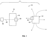
- FIG. 1 illustrates a charging system 10 for charging a mobile device 12 in accordance with an exemplary embodiment.
- the charging system 10 includes a supply charging device 20 and a mobile charging device 30.
- the mobile charging device 30 is provided on the mobile device 12.
- the supply charging device 20 is provided on a charging component 14.
- the charging component 14 may be fixed, such as to a wall or panel 16. In other various embodiments, the charging component 14 may be a movable charging component, such as a charging station.
- the charging component 14 may be provided in a room or building in a fixed location and the mobile device 12 may be separated from the charging component 14 and returned to the charging component 14 to recharge the mobile device 12.
- the supply charging device 20 receives power from a power supply 40, such as via a power wires 42 routed between the power supply 40 and the supply charging device 20.
- the mobile device 12 is an autonomous mobile device that is movable within an environment to perform a task and return to the supply charging device 20 to charge the autonomous mobile device 12.
- the mobile charging device 30 may be mated to the supply charging device 20 to recharge the mobile device 12.
- the mobile device 12 may be a mobile robot, such as for used to perform tasks in a factory, a hotel, a store or another environment.
- the mobile robot may be used to scan items on shelves, deliver items from one location to another location, or perform other tasks.
- the mobile charging device 30 is mounted to a body 18 of the mobile device 12.
- the mobile charging device 30 may have a limited amount of floating movement relative to the body 18 to align the mobile charging device 30 relative to the supply charging device 20 during mating.
- the supply charging device 20 is capable of accommodating misalignment of the mobile charging device 30 when the mobile device 12 returns to the charging component 14 by moving or floating relative to the panel 16 to align the supply charging device 20 with the mobile charging device 30.
- the supply charging device 20 may allow floating movement relative to the panel 16 of approximately 10 mm or more.
- FIG. 2 illustrates a charging system 100 for charging a mobile device 102 in accordance with an exemplary embodiment.
- the charging system 100 includes a supply charging device 200 and a mobile charging device 300.
- the mobile charging device 300 is provided on the mobile device 102 and includes a mating end 302 configured to be mated with the supply charging device 200.
- the supply charging device 200 is provided on a charging component 104 and includes a mating end 202 configured to be mated with the mobile charging device 300.
- the supply charging device 200 is coupled to a panel 106 of the charging component 104.
- the mobile charging device 300 is coupled to a body 108 of the mobile device 102.
- the mobile device 102 is configured to be separated from the charging component 104 and returned to the charging component 104 to recharge the mobile device 102.
- the mobile charging device 300 receives power from the supply charging device 200 when coupled thereto.
- the mobile charging device 300 includes a receiver power connector 310 having a receiver housing 312.
- the receiver housing 312 has a receiver flange 314 configured to be mounted to the body 108 of the mobile device 102.
- the receiver housing 312 has a receiver base 316 including receiver power contact channels 318 that hold receiver power contacts 320.
- the receiver power contacts 320 are illustrated as blade contacts; however, other types of power contacts may be used in alternative embodiments, such as pins, sockets, spring beams, and the like.
- the receiver housing 312 includes receiver signal contact channels 322 that hold receiver signal contacts 324.
- the receiver housing 312 includes a guide feature 330 to guide mating of the mobile charging device 300 with the supply charging device 200.
- the guide feature 330 includes a funnel 332 having an opening 334.
- the funnel 332 has angled guide walls 336 between the opening 334 and a receptacle 338 at the receiver base 316.
- the guide walls 336 are provided on all four sides of the funnel 332 to guide mating from above, from below, from a first side and from a second side (for example, providing X and Y guidance).
- the receiver power contacts 320 extend into the receptacle 338 for mating with the supply charging device 200.
- the guide walls 336 guide alignment of the supply charging device 200 and the mobile charging device 300 with the mobile device 102 returns to the charging component 104.
- the funnel 332 is wider and taller than the receptacle 338 to gather the supply charging device 200 during mating.
- the funnel 332 accommodates misalignment of the mobile charging device 300 with the supply charging device 200 during mating.
- the funnel 332 accommodates horizontal misalignment (for example, misalignment from either side) and accommodates vertical misalignment (for example, misalignment from above or from below).
- the funnel 332 has additional width relative to the receptacle 338 at both sides and has additional height relative to the receptacle 338 from both above and below.
- the supply charging device 200 includes a supply power connector 210 having a supply housing 212.
- the supply housing 212 has a supply flange 214 configured to be mounted to the panel 106.
- the supply housing 212 includes supply power contact channels 218 that receive supply power contacts 220.
- the supply housing 212 includes supply signal contact channels 222 that receive supply signal contacts 224.
- the supply power contacts 220 are illustrated as dual spring beam contacts; however, other types of power contacts may be used in alternative embodiments, such as pins, sockets, blades, and the like.
- the supply power contact 220 and the supply signal contact 224 are configured to be electrically connected to the receiver power contacts 320 and the receiver signal contacts 324 when the mobile charging device 300 is mated with the supply charging device 200.
- the supply housing 212 includes a guide member 230 extending forward from the flange 214.
- the guide member 230 is configured to be received in the funnel 332 of the receiver housing 312 through the opening 334 to locate the supply charging device 200 relative to the mobile charging device 300.
- the guide member 230 includes a nose 232 and a cone 234 extending between the nose 232 and the flange 214.
- the nose 232 is configured to be received in the receptacle 338.
- the nose 232 may have a complementary shape to the receptacle 338.
- the cone 234 is configured to engage the funnel 332 to position the guide member 230 in the guide feature 330.
- the cone 234 may have a complementary shape to the funnel 332.
- Figure 3 is a rear perspective view of the charging component 104 showing a portion of the supply charging device 200 configured to be mated to the panel 106.
- the panel 106 includes a panel cutout 120 configured to receive the supply charging device 200.
- the panel cutout 120 is defined by edges 122 extending between a front 124 and a rear 126 of the panel 106.
- the front 124 faces an exterior of the charging component 104 and the rear 126 faces an interior of the charging component 104.
- the supply housing 212 extends between a front 240 and a rear 242.
- the mating end 202 is provided at the front 240 of the supply housing 212.
- the supply housing 212 includes a supply base 216 extending rearward from the supply flange 214 to the rear 242 of the supply housing 212.
- the supply power contact channels 218 and the supply signal contact channels 222 extend through the supply base 216.
- the supply power contacts 220 are located in the supply base 216 and/or extend rearward from the supply base 216 for termination to power wires or a power connector. In the illustrated embodiment, the supply power contacts 220 include wire clamps configured to receive power wires.
- the supply housing 212 includes separating walls between the supply power contacts 220 to electrically isolate the supply power contacts 220, such as to prevent electrical arcing.
- the supply housing 212 includes separating walls between the supply power contact 228 and the supply signal contacts 224 to electrically isolate the supply power contacts 220 from the supply signal contacts 224.
- the supply signal contacts 224 are located in the supply base 216 and/or extend rearward from the supply base 216 for termination to signal wires or a signal connector.
- the supply signal contacts 224 may include pins configured to be mated to sockets terminated to ends of the signal wires.
- the supply signal contacts 224 may include crimp barrels configured to be crimped to signal wires.
- Other types of terminations may be provided in alternative embodiments, such as wire clamps, insulation displacement contacts, pin contacts, socket contacts, and the like.
- the supply charging device 200 includes mounting springs 250, 252, 254 coupled to the supply housing 212 at the rear 242 of the supply housing 212.
- the mounting springs 250, 252, 254 are configured to engage the panel 106 to allow the supply power connector 210 to float relative to the panel 106 for alignment of the mating end 202 of the supply power connector 210 with the receiver power connector 310 (shown in Figure 2 ).
- the mounting springs 250, 252, 254 are compressible to allow the supply housing 212 to move relative to the panel 106 to change a position of the mating end 202 of the supply power connector 210 relative to the panel 106 for mating with the receiver power connector 310.
- the mounting spring 250 is located at a first side 244 of the base 216, the mounting spring 252 is located at a second side 246 of the base 216, and the mounting spring 254 is located below the base 216.
- Other locations are possible in alternative embodiments.
- a mounting spring may additionally or alternatively be provided above the base 216 in alternative embodiments.
- the mounting spring 250 includes a fixed end 260 coupled to the supply housing 212 and a free end 262 configured to be coupled to the panel 106.
- the mounting spring 250 is compressible such that the free end 262 is movable relative to the fixed end 260, such as in a direction toward the fixed end 260.
- the supply housing 212 includes a slot 264 at the rear 242 that receives the free end 262 of the mounting spring 250.
- the free end 262 is slidable within the slot 264.
- the slot 264 controls movement of the free end 262 relative to the fixed end 260.
- the supply housing 212 includes locating features 266 extending from the supply flange 214 at the rear 242.
- the locating features 266 are cylindrical posts. Other types of locating features may be used in alternative embodiments.
- the locating features 266 may be provided on the supply base 216 in alternative embodiments.
- the locating features 266 are configured be received in the panel cutout 120 and are used to locate the supply power connector 210 relative to the panel 106. For example, the locating features 266 may engage the edges 122 to control or limit floating movement of the supply power connector 210 relative to the panel 106.
- the locating features 266 may limit over deflection of the mounting springs 250, 252, 254.
- Figure 4 is a rear perspective view of the charging component 104 showing a portion of the supply charging device 200 mated to the panel 106.
- Figure 5 is a rear view of the charging component 104 showing a portion of the supply charging device 200 mated to the panel 106.
- the supply flange 214 is located forward of the panel 106.
- the supply base 216 extends into and through the panel cutout 120 to the interior of the charging component 104.
- the mounting springs 250, 252, 254 extend into the panel cutout 120 and engage the panel 106.
- the mounting spring 250 engages a right edge 122 of the panel cutout 120
- the mounting spring 252 engages a left edge 122 of the panel cutout 120
- the mounting spring 254 engages a bottom edge 122 of the panel cutout 120.
- the mounting springs 250, 252, 254 bias the supply power connector 210 to a resting position relative to the panel 106.
- the supply base 216 may be approximately centered within the panel cutout 120 in the resting position.
- the supply power connector 210 is movable from the resting position to an offset position (for example, movable to the right side, to the left side, upward, and/or downward), such as when the mobile charging device 300 (shown in Figure 2 ) engages the supply charging device 200 to align the supply charging device 200 with the mobile charging device 300.
- the mounting spring 250, the mounting spring 252, and/or the mounting spring 254 may be compressed when the supply power connector 210 moves to the offset position.
- the mounting springs 250, 252, 254 return the supply power connector 210 from the offset position to the resting position when the supply power connector 210 is released.
- the mounting spring 250 biases the supply power connector 210 in a first direction 251 relative to the panel 106.
- the mounting spring 252 biases the supply power connector 210 in a second direction 253 relative to the panel 106.
- the mounting spring 254 biases the supply power connector 210 in a third direction 255 relative to the panel 106.
- the first direction 251 and the second direction 253 are parallel to each other in opposing directions.
- the third direction 255 is perpendicular to the first and second directions 251, 253.
- the mounting springs 250, 252 control horizontal positioning (for example, side-to-side) of the supply charging device 200 relative to the panel 106.
- the widths of the mounting springs 250, 252 control the amount of horizontal offset or float allowed by the supply charging device 200 within the panel cutout 120.
- the mounting spring 254 controls vertical positioning (for example, up and down) of the supply charging device 200 relative to the panel 106.
- the height of the mounting spring 254 controls the amount of vertical offset or float allowed by the supply charging device 200 within the panel cutout 120.
- Figure 6 is a rear view of the charging component 104 showing the supply charging device 200 in an offset position relative to the panel 106.
- Figure 6 illustrates the supply power connector 210 shifted downward and shifted to the right relative to the panel 106. In such position, the mounting spring 250 is compressed and the mounting spring 254 is compressed. The locating features 266 engage the edges 122 of the panel cutout 120 to limit movement of the supply power connector 210 relative to the panel 106. When the supply power connector 210 is released, the mounting springs 250, 254 are configured to return the supply power connector 210 to the resting position (shown in Figure 5 ).
- FIG. 7 is a rear perspective view of the charging component 104 showing a portion of the supply charging device 200 mounted to the panel 106.
- the supply charging device 200 includes a retaining plate 270 coupled to the rear 242 of the supply housing 212.
- the retaining plate 270 is used to mount the supply power connector 210 to the panel 106.
- the retaining plate 270 includes a front 272 and a rear 274.
- the front 272 faces the panel 106.
- Fasteners 276 are used to secure the retaining plate 270 to the supply housing 212.
- the fasteners 276 may be secured to the locating features 266.
- the retaining plate 270 includes an opening 278 configured to receive the supply base 216.
- the opening 278 may receive portions of the mounting springs 250, 252.
- the opening 278 may receive portions of the mounting spring 254 in various embodiments.
- FIG 8 is a rear perspective view of the charging component 104 showing the supply charging device 200 mounted to the panel 106.
- the panel 106 is captured in a panel gap 280 between the front 272 of the retaining plate 270 and the rear 242 of the supply flange 214.
- the retaining plate 270 is coupled to the supply power connector 210 such that the retaining plate 270 is movable relative to the panel 106 with the supply power connector 210.
- FIG 9 is a rear perspective view of the charging component 104 showing the supply charging device 200 mounted to the panel 106.
- Power wires 132 are terminated to the supply power contacts 220.
- Signal wires 134 are terminated to the supply signal contacts 224 (shown in Figure 2 ).
- the signal wires 134 extend from a connector housing 136 coupled to the supply base 216.
- the supply signal contacts 224 may be integrated into the connector housing 136 and terminated to the signal wires 134.
- the supply signal contacts 224 are loaded into the supply housing 212 when the connector housing 136 is coupled to the supply housing 212.
- Figure 10 is a rear perspective view of the charging component 104 showing the supply charging device 200 mounted to the panel 106.
- a wire housing 138 is shown in Figure 10 surrounding the power wires 132.
- the wire housing 138 may restrict access to the terminating ends of the power wires 132.
- the wire housing 138 may provide strain relief for the power wires 132.
- the wire housing 138 may hold power terminals configured to be mated to the supply power contacts 220, such as at a pluggable interface.
- Figure 11 is a front perspective view of a portion of the mobile device 102 showing the mobile charging device 300 positioned for mounting to the body 108.
- the body 108 includes a body cutout 110 configured to receive the mobile charging device 300.
- the body cutout 110 is defined by edges 112 extending between a front 114 and a rear 116 of the body 108.
- the front 114 faces an exterior of the mobile device 102 and the rear 116 faces an interior of the mobile device 102.
- FIG 12 is a rear perspective view of the mobile charging device 300 in accordance with an exemplary embodiment.
- the receiver housing 312 extends between a front 340 and a rear 342.
- the mating end 302 is provided at the front 340 of the receiver housing 312.
- the receiver base 316 extends rearward from the receiver flange 314 to the rear 342 of the receiver housing 312.
- the receiver power contact channels 318 and the receiver signal contact channels 322 extend through the receiver base 316.
- the receiver power contacts 320 are located in the receiver base 316 and/or extend rearward from the receiver base 316 for termination to power wires or a power connector.
- the receiver power contacts 320 include wire clamps configured to receive power wires.
- the supply housing 312 includes separating walls between the receiver power contacts 320 to electrically isolate the receiver power contacts 320, such as to prevent electrical arcing.
- the supply housing 312 includes separating walls between the receiver power contact 320 and the receiver signal contacts 324 to electrically isolate the receiver power contacts 320 from the receiver signal contacts 324.
- the receiver signal contacts 324 are located in the receiver base 316 and/or extend rearward from the receiver base 316 for termination to signal wires or a signal connector.
- the receiver signal contacts 324 are configured to be coupled to signal wires.
- Figure 13 is a rear perspective view of the mobile device 102 showing the mobile charging device 300 mounted to the body 108.
- Power wires 142 are terminated to the receiver power contacts 320.
- Signal wires 144 are configured to be electrically connected to the receiver signal contacts 324 (shown in Figure 3 ).
- the signal wires 144 extend from a connector housing 146 coupled to the receiver base 316.
- the receiver signal contacts 324 may be integrated into the connector housing 146 and terminated to the signal wires 144.
- the receiver signal contacts 324 are loaded into the receiver housing 312 when the connector housing 146 is coupled to the receiver housing 312.
- the receiver power connector 310 includes a strain relief component 148 to provide strain relief for the receiver power wires 142.
- the strain relief component 148 includes a support tab and a wire tie securing the power wires 142 to the support tab. Other types of strain relief components may be used in alternative embodiments.
- Figure 14 is a cross-sectional view of the charging system 100 in accordance with an exemplary embodiment showing the mobile charging device 300 being mated with the supply charging device 200 in a mating direction 150.
- the mobile charging device 300 is offset or misaligned relative to the supply charging device 200.
- the mobile charging device 300 is offset lower than the supply charging device 200.
- Figures 16-19 illustrate other examples of misaligned mating between the mobile charging device 300 and the supply charging device 200.
- the supply charging device 200 is movable relative to the panel 106 to align the mating end 202 of the supply charging device 200 with the mating end 302 of the mobile charging device 300.
- the guide member 230 engages the guide features 330 to align the mating ends 202, 302.
- the nose 232 is received in the funnel 332 through the opening 334.
- the guide walls 336 engage the guide member 230 and forced the guide member 230 in an offsetting direction 152.
- the offsetting direction 152 is in a downward direction; however, the offsetting direction 152 may be in a different direction in alternative embodiments, including an upward direction and/or a sideways direction.
- the mounting spring 254 is compressed as the supply power connector 210 is shifted in the offsetting direction 152.
- the supply power connector 210 is shifted relative to the panel 106 to align the nose 232 with the receptacle 338.
- the nose 232 rides along the guide wall 336 and is received in the receptacle 338 as the mobile charging device 300 is moved in the mating direction 150.
- the supply power contacts 220 are mated with the receiver power contacts 320 as the mobile charging device 300 is moved in the mating direction 150.
- Figures 15-19 illustrate examples of mating scenarios between the mobile charging device 300 and the supply charging device 200.
- Figure 15 illustrates the mobile charging device 300 aligned with the supply charging device 200. When aligned, the supply charging device 200 is not required to move in any direction to mate the receiver power connector 310 with the supply power connector 210.
- Figure 16 illustrates the mobile charging device 300 misaligned in an upper left offset position relative to the supply charging device 200.
- the supply power connector 210 is required to be shifted relative to the panel 106 (shown in Figure 14 ) upward and to the left for proper mating with the supply charging device 200.
- Figure 17 illustrates the mobile charging device 300 misaligned in an upper right offset position relative to the supply charging device 200.
- the supply power connector 210 is required to be shifted relative to the panel 106 (shown in Figure 14 ) upward and to the right for proper mating with the supply charging device 200.
- Figure 18 illustrates the mobile charging device 300 misaligned in a lower left offset position relative to the supply charging device 200.
- the supply power connector 210 is required to be shifted relative to the panel 106 (shown in Figure 14 ) downward and to the left for proper mating with the supply charging device 200.
- Figure 19 illustrates the mobile charging device 300 misaligned in a lower right offset position relative to the supply charging device 200.
- the supply power connector 210 is required to be shifted relative to the panel 106 (shown in Figure 14 ) downward and to the right for proper mating with the supply charging device 200.
- Figure 20 illustrates a charging system 400 in accordance with an exemplary embodiment including a supply charging device 500 and a mobile charging device 600.
- Figure 21 is a front perspective view of the mobile charging device 600 in accordance with an exemplary embodiment.
- Figure 22 is a front perspective view of the supply charging device 500 in accordance with an exemplary embodiment.
- the charging system 400 is similar to the charging system 100 (shown in Figure 2 ); however, the charging system 400 includes different types of power contacts and signal contacts.
- the mobile charging device 600 is provided on a mobile device 402 and includes a mating end 602 configured to be mated with the supply charging device 500.
- the supply charging device 500 is provided on a charging component 404 and includes a mating end 502 configured to be mated with the mobile charging device 600.
- the supply charging device 500 is configured to be coupled to a panel, such as the panel 106 (shown in Figure 2 ).
- the mobile charging device 600 is configured to be coupled to a body of a mobile device, such as the body 108.
- the mobile device 402 is configured to be separated from the charging component 404 and returned to the charging component 404 to recharge the mobile device 402.
- the mobile charging device 600 receives power from the supply charging device 500 when coupled thereto.
- the mobile charging device 600 includes a receiver power connector 610 having a receiver housing 612.
- the receiver housing 612 has a receiver flange 614 configured to be mounted to the body 108 of the mobile device 402.
- the receiver housing 612 has a receiver base 616 including receiver power contact channels 618 that hold receiver power contacts 620.
- the receiver power contacts 620 are illustrated as blade contacts; however, other types of power contacts may be used in alternative embodiments, such as pins, sockets, spring beams, and the like.
- the receiver housing 612 includes receiver signal contact channels 622 that hold receiver signal contacts 624.
- the receiver housing 612 includes a guide feature 630 to guide mating of the mobile charging device 600 with the supply charging device 500.
- the guide feature 630 includes a funnel 632 having an opening 634.
- the funnel 632 has angled guide walls 636 between the opening 634 and a receptacle 638 at the receiver base 616.
- the receiver power contacts 620 extend into the receptacle 638 for mating with the supply charging device 500.
- the guide walls 636 guide alignment of the supply charging device 500 and the mobile charging device 600 with the mobile device 402 returns to the charging component 404.
- the funnel 632 accommodates horizontal misalignment (for example, misalignment from either side) and accommodates vertical misalignment (for example, misalignment from above or from below).
- the supply charging device 500 includes a supply power connector 510 having a supply housing 512.
- the supply housing 512 extends between a front 540 and a rear 542.
- the mating end 502 is provided at the front 540 of the supply housing 512.
- the supply housing 512 has a supply flange 514 configured to be mounted to the panel 106.
- the supply housing 512 includes supply power contact channels 518 that receive supply power contacts 520.
- the supply housing 512 includes supply signal contact channels 522 that receive supply signal contacts 524.
- the supply power contacts 520 are illustrated as spring beam contacts; however, other types of power contacts may be used in alternative embodiments, such as pins, sockets, blades, spring beams, and the like.
- the supply power contact 520 and the supply signal contact 524 are configured to be electrically connected to the receiver power contacts 620 and the receiver signal contacts 624 when the mobile charging device 600 is mated with the supply charging device 500.
- the supply housing 512 includes a guide member 530 extending forward from the flange 514.
- the guide member 530 is configured to be received in the funnel 632 of the receiver housing 612 through the opening 634 to locate the supply charging device 500 relative to the mobile charging device 600.
- the guide member 530 includes a nose 532 and a cone 534 extending between the nose 532 and the flange 514.
- the nose 532 is configured to be received in the receptacle 638.
- FIG 23 is a rear perspective view of the supply charging device 500 in accordance with an exemplary embodiment.
- the supply housing 512 includes a supply base 516 extending rearward from the supply flange 514 to the rear 542 of the supply housing 512.
- the supply base 516 receives a contact holder 526 that holds the supply power contacts 520 (shown in Figure 22 ).
- the power wires 132 extend from the contact holder 526.
- the supply charging device 500 includes mounting springs 550, 552, 554 coupled to the supply housing 512 at the rear 542 of the supply housing 512.
- the mounting springs 550, 552, 554 are configured to engage the panel 106 to allow the supply power connector 510 to float relative to the panel 106 for alignment of the mating end 502 of the supply power connector 510 with the receiver power connector 610 (shown in Figure 21 ).
- the mounting springs 550, 552, 554 are compressible to allow the supply housing 512 to move relative to the panel 106 to change a position of the mating end 502 of the supply power connector 510 relative to the panel 106 for mating with the receiver power connector 610.
- the mounting spring 550 includes a fixed end 560 coupled to the supply housing 512 and a free end 562 configured to be coupled to the panel 106.
- the mounting spring 550 is compressible such that the free end 562 is movable relative to the fixed end 560.
- the supply housing 512 includes a slot 564 at the rear 542 that receives the free end 562 of the mounting spring 550.
- the supply housing 512 includes locating features 566 extending from the supply flange 514 at the rear 542.
- the locating features 566 are cylindrical posts. Other types of locating features may be used in alternative embodiments.
- the locating features 566 may be provided on the supply base 516 in alternative embodiments.
- the locating features 566 are configured be engage the panel 106 to locate the supply power connector 510 relative to the panel 106.
- Figure 24 is a rear perspective view of the supply charging device 500 mated to the panel 106.
- the supply flange 514 is located forward of the panel 106.
- the supply base 516 extends into and through the panel cutout 120 to the interior of the charging component 404.
- the mounting springs 550, 552, 554 extend into the panel cutout 120 and engage the panel 106.
- the mounting springs 550, 552, 554 bias the supply power connector 510 to a resting position relative to the panel 106.
- the supply power connector 510 is movable from the resting position to an offset position (for example, movable to the right side, to the left side, upward, and/or downward), such as when the mobile charging device 600 (shown in Figure 21 ) engages the supply charging device 500 to align the supply charging device 500 with the mobile charging device 600.
- the mounting springs 550, 552, 554 return the supply power connector 510 from the offset position to the resting position when the supply power connector 510 is released.
- the mounting springs 550, 552 control horizontal positioning (for example, side-to-side) of the supply charging device 500 relative to the panel 106.
- the mounting spring 554 controls vertical positioning (for example, up and down) of the supply charging device 500 relative to the panel 106.
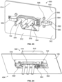
- FIG 25 is a rear perspective view of the charging component 404 showing a portion of the supply charging device 500 mounted to the panel 106.
- the supply charging device 500 includes a retaining plate 570 coupled to the rear 542 of the supply housing 512.
- the retaining plate 570 is used to mount the supply power connector 510 to the panel 106.
- the retaining plate 570 includes a front 572 and a rear 574. The front 572 faces the panel 106.
- Fasteners 576 are used to secure the retaining plate 570 to the supply housing 512.
- the fasteners 576 may be secured to the locating features 566.
- the retaining plate 570 includes an opening 578 configured to receive the supply base 516.
- the opening 578 may receive portions of the mounting springs 550, 552.
- the opening 578 may receive portions of the mounting spring 554 in various embodiments.
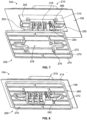
- Figure 26 is a rear perspective view of the mobile charging device 600 in accordance with an exemplary embodiment.
- Figure 27 is a rear perspective, exploded view of the mobile charging device 600 in accordance with an exemplary embodiment.
- the receiver housing 612 extends between a front 640 and a rear 642.
- the mating end 602 is provided at the front 640 of the receiver housing 612.
- the receiver base 616 extends rearward from the receiver flange 614 to the rear 642 of the receiver housing 612.
- the receiver signal contacts 624 are pogo contacts; however, other types of contact may be used in alternative embodiments.
- the receiver base 616 receives a contact holder 626 in a cavity 628 of the receiver base 616.
- the contact holder 626 holds the receiver power contacts 620 ( Figure 27 ).
- the power wires 142 extend from the contact holder 626.
- the receiver power contacts 620 are configured be side loaded into corresponding contact channels in the contact holder 626, such as through the top side and/or the bottom side of the contact holder 626.
- the receiver power contacts 620 may be end loaded into the contact holder 626, such as through the rear end of the contact holder 626.
- a contact lock 629 is used to lock the receiver power contacts 620 in the contact holder 626.
- the contact holder 626 with the receiver power contacts 620 loaded therein and the power wires 142 extending therefrom, is configured to be rear loaded into the cavity 628 of the receiver base 616.
- the contact lock 629 is then coupled to the receiver base 616 to lock the contact holder 626 in the cavity 628 and to lock the receiver power contacts 620 in the contact holder 626.
- Figure 28 is a rear perspective, exploded view of the supply charging device 500 in accordance with an exemplary embodiment.
- Figure 28 illustrates the mounting springs 550, 552, 554 configured to be plugged into the supply housing 512.
- Figure 28 illustrates the supply signal contacts 524 configured to be loaded into the supply housing 512.
- the supply signal contacts 524 are pogo contacts; however, other types of contact may be used in alternative embodiments
- Figure 28 illustrates the contact holder 526 used to hold the supply power contacts 520.
- the contact holder 526 is configured to be received in a cavity 528 of the supply base 516.
- the contact holder 526 holds the supply power contacts 520.
- the power wires 132 extend from the contact holder 526.
- the supply power contacts 520 are configured be side loaded into corresponding contact channels in the contact holder 526, such as through the top side and/or the bottom side of the contact holder 526.
- the supply power contacts 520 may be end loaded into the contact holder 526, such as through the rear end of the contact holder 526.
- a contact lock 529 is used to lock the supply power contacts 520 in the contact holder 526.
- the contact holder 526 with the supply power contacts 520 loaded therein and the power wires 142 extending therefrom, is configured to be rear loaded into the cavity 528 of the supply base 516.
- the contact lock 529 is then coupled to the supply base 516 to lock the contact holder 526 in the cavity 528 and to lock the supply power contacts 520 in the contact holder 526.
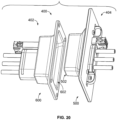
- Figure 29 is a perspective view of the charging component 404 showing the supply charging device 500 mounted to the panel 106.
- the panel 106 is captured in a panel gap 580 between the front 572 of the retaining plate 570 and the rear 542 of the supply flange 514.
- the retaining plate 570 is coupled to the supply power connector 510 such that the retaining plate 570 is movable relative to the panel 106 with the supply power connector 510.
- the panel gap 580 has a width greater than a width of the panel 106 to allow the supply power connector 510 to be angularly offset with respect to the panel 106.
- the supply power connector 510 may be rotated relative to the panel 106 such that the supply flange 514 is nonparallel to the panel 106.
- the angular offset allows mating with the mobile charging device 600 in a mating direction non-perpendicular to the panel 106.
- the supply power connector 510 may be angularly offset by approximately 5° relative to the panel 106.
- the amount of angular offset may be greater or less than 5° in alternative embodiments by controlling the panel gap width.
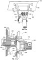
- Figure 30 is a cross-sectional view of the charging system 400 in accordance with an exemplary embodiment showing the mobile charging device 600 being mated with the supply charging device 500 in a mating direction 450.
- the mobile charging device 600 is offset or misaligned relative to the supply charging device 500.
- the mobile charging device 600 is horizontally offset (for example, to the right) relative to the supply charging device 500.
- the supply charging device 500 is movable relative to the panel 106 to align the mating end 502 of the supply charging device 500 with the mating end 602 of the mobile charging device 600.
- the guide member 530 engages the guide features 630 to align the mating ends 502, 602.
- the nose 532 is received in the funnel 632 through the opening 634.
- the guide walls 636 engage the guide member 530 and forced the guide member 530 in an offsetting direction 452.
- the offsetting direction 452 is in a sideways direction; however, the offsetting direction 452 may be in a different direction in alternative embodiments, including an upward direction, a downward direction and/or at another angular direction.
- Figure 31 is a cross-sectional view of the charging system 400 in accordance with an exemplary embodiment showing the mobile charging device 600 partially mated with the supply charging device 500 in the mating direction 450.
- the mounting spring 552 is compressed as the supply power connector 510 is shifted in the offsetting direction 452.
- the supply power connector 510 is shifted relative to the panel 106 to align the nose 532 with the receptacle 638.
- the nose 532 rides along the guide wall 636 toward the receptacle 638 as the mobile charging device 600 is moved in the mating direction 450.
- Figure 32 is a cross-sectional view of the charging system 400 in accordance with an exemplary embodiment showing the mobile charging device 600 fully mated with the supply charging device 500.
- the mounting spring 552 is compressed.
- the supply the connector 510 is shifted to the offset position relative to the panel 106.
- the supply power contacts 520 are mated with the receiver power contacts 620 in the mated position.
- Figure 33 illustrates the charging system 400 in accordance with an exemplary embodiment.
- the supply charging device 500 includes an electrostatic discharge contact 504 and the mobile charging device 600 includes an electrostatic discharge contact 604.
- the electrostatic discharge contact 504 engages the electrostatic discharge contact 604 when the mobile charging device 600 is mated with the supply charging device 500.
- the electrostatic discharge contacts 504, 604 are mated prior to the power contacts 520, 620 being mated.
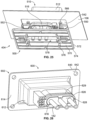
- Figure 34 illustrates a charging system 700 in accordance with an exemplary embodiment including a supply charging device 800 and a mobile charging device 900.
- Figure 35 illustrates the charging system 700 in accordance with an exemplary embodiment including the supply charging device 800 and the mobile charging device 900.
- the charging system 700 is similar to the charging systems 100, 400; however, the charging devices are circular rather than being rectangular.
- the mobile charging device 900 is provided on a mobile device 702 and includes a mating end 902 configured to be mated with the supply charging device 800.
- the supply charging device 800 is provided on a charging component 704 and includes a mating end 802 configured to be mated with the mobile charging device 900.
- the supply charging device 800 is configured to be coupled to a panel 706 (shown in Figure 36 ).
- the mobile charging device 900 is configured to be coupled to a body 708 (shown in Figure 36 ) of the mobile device 702.
- the mobile device 702 is configured to be separated from the charging component 704 and returned to the charging component 704 to recharge the mobile device 702.
- the mobile charging device 900 receives power from the supply charging device 800 when coupled thereto.
- the mobile charging device 900 includes a receiver power connector 910 having a receiver housing 912.
- the receiver housing 912 has a receiver flange 914 configured to be mounted to the body 708 of the mobile device 702.
- the receiver housing 912 holds receiver power contacts 920.
- the receiver housing 912 includes a guide feature 930 to guide mating of the mobile charging device 900 with the supply charging device 800.
- the guide feature 930 includes a funnel 932 having an opening 934.
- the funnel 932 has angled guide walls 936 between the opening 934 and a receptacle 938.
- the guide walls 936 guide alignment of the supply charging device 800 and the mobile charging device 900 with the mobile device 702 returns to the charging component 704.
- the funnel 932 accommodates horizontal misalignment (for example, misalignment from either side) and accommodates vertical misalignment (for example, misalignment from above or from below).
- the supply charging device 800 includes a supply power connector 810 having a supply housing 812.
- the supply housing 812 extends between a front 840 and a rear 842.
- the mating end 802 is provided at the front 840 of the supply housing 812.
- the supply housing 812 has a supply flange 814 configured to be mounted to the panel 706.
- the supply housing 812 holds supply power contacts 820.
- the supply housing 812 includes a guide member 830 extending forward from the flange 814.
- the guide member 830 is configured to be received in the funnel 932 of the receiver housing 912 through the opening 934 to locate the supply charging device 800 relative to the mobile charging device 900.
- the supply charging device 800 includes mounting springs 850 coupled to the supply housing 812 configured to engage the panel 106 to allow the supply power connector 810 to float relative to the panel 106 for alignment of the mating end 802 of the supply power connector 810 with the receiver power connector 910.
- Figure 36 is a cross-sectional view of the charging system 700 in accordance with an exemplary embodiment showing the mobile charging device 900 partially mated with the supply charging device 800 in the mating direction 750.
- the mounting spring 850 allows floating movement of the supply power connector 810 to an offset position relative to the panel 706 to align the mating end 802 of the supply charging device 800 with the mating end 902 of the mobile charging device 900.
- the supply power connector 810 is shifted relative to the panel 706 to align the guide member 830 with the receptacle 938.
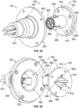
- Figure 37 is a perspective view of the charging system 700 showing the supply charging device 800 mated to the panel 706 and the mobile charging device 900 mated to the body 708 of the mobile device 702.
- the panel 706 includes an enclosure 760.
- the supply charging device 800 is mounted within the enclosure 760.
- the supply charging device 800 is recessed from a front of the panel 706 within the enclosure 760.
- the mobile device 702 includes a plug 762 extending outward from the body 708.
- the mobile charging device 900 is mounted to the plug 762.
- the plug 762 is configured to be received in the enclosure 760.
- the walls of the enclosure 760 are used to guide the plug 762.
- the walls of the enclosure 760 may be used for course alignment of the mobile charging device 900 with the supply charging device 800.
- the guide feature 930 and the guide member 830 may then be used for fine alignment of the mobile charging device 900 with the supply charging device 800.
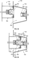
- Figure 38 is a cross-sectional view of the charging system 700 showing the mobile device 702 being mated with the charging component 704.
- the mobile charging device 900 is offset relative to the supply charging device 800.
- the enclosure 760 is used to guide the plug 762 into general alignment such that the guide feature 930 may be used to interface with the guide member 830 during mating of the mobile charging device 900 with the supply charging device 800.
- Enclosure walls 764 are angled from front to rear two center the plug 762 within the enclosure 760.
- Figure 39 is a cross-sectional view of the charging system 700 showing the mobile device 702 being mated with the charging component 704.
- the enclosure walls 764 guide the plug 762 toward the center of the enclosure 760.
- the enclosure walls 764 forced the plug 762 and the receiver power connector 910 into general alignment with the supply power connector 810.
- the guide member 830 is aligned with the funnel 932 by the enclosure walls 764. Further mating of the mobile charging device 900 with the supply charging device 800 causes the guide member 830 to be aligned with the receptacle 938.
- the enclosure walls 764 and/or the funnel 932 may be used to orient the mobile charging device 900 and the supply charging device 800.
- FIG 40 is a cross-sectional view of a portion of the mobile charging device 900 in accordance with an exemplary embodiment.
- the receiver power connector 910 of the mobile charging device 900 is coupled to the body 708 of the mobile device 702 by a floating coupler 950 to allow a limited amount of floating movement of the receiver power connector 910 relative to the body 708 of the mobile device 702.
- the floating coupler 950 includes a flange 952 having a groove 954 that receives the body 708.
- the groove 954 is oversized relative to the opening in the body 708 to allow a limited amount of floating movement of the floating coupler 950 relative to the body 708.
- the receiver power connector 910 is able to move relative to the body 708, such as to align the receiver power connector 910 with the supply power connector 810 during mating.
Landscapes
- Engineering & Computer Science (AREA)
- Mechanical Engineering (AREA)
- Power Engineering (AREA)
- Transportation (AREA)
- Robotics (AREA)
- Charge And Discharge Circuits For Batteries Or The Like (AREA)
- Details Of Connecting Devices For Male And Female Coupling (AREA)
Claims (15)
- Dispositif de recharge d'alimentation (200) pour un dispositif mobile (102), le dispositif de recharge d'alimentation (200) comprenant :un connecteur de puissance d'alimentation (210) ayant un logement (212) s'étendant entre une partie avant (240) et une partie arrière (242), le connecteur de puissance d'alimentation (210) ayant une extrémité d'accouplement (202) au niveau de la partie avant (240), le logement (212) ayant une bride (214) configurée pour être montée sur un panneau (106), le logement (212) ayant une base (216) configurée pour s'étendre vers l'arrière à partir de la bride (214) à travers une découpe de panneau (120) dans le panneau (106), le logement (212) incluant des canaux pour contacts de puissance (218) s'étendant à travers la base (216), le logement (212) incluant un élément de guidage (230) s'étendant vers l'avant à partir de la bride (214), l'élément de guidage (230) étant configuré pour se mettre en prise avec un accessoire de guidage (330) du dispositif mobile (102) afin de localiser un connecteur de puissance de récepteur (310) du dispositif mobile (102) relativement au connecteur de puissance d'alimentation (210) du dispositif de recharge d'alimentation (200), le connecteur de puissance d'alimentation (210) incluant des contacts de puissance (220) reçus dans les canaux pour contacts de puissance (218) ; un ressort de montage (250, 252, 254) étant couplé au logement (212) ;caractérisé en ce que le dispositif de recharge d'alimentation (200) comprend en outre une plaque de retenue (270) couplée à la partie arrière du logement (212), un intervalle de panneau (280) étant défini entre la plaque de retenue (270) et la partie arrière (242) du logement (212) configuré pour recevoir le panneau (106) entre la bride (214) et la plaque de retenue (270) ;le ressort de montage (250, 252, 254) s'étendant à l'arrière de la bride (214), le ressort de montage (250, 252, 254) étant configuré pour être reçu dans la découpe de panneau (120), le ressort de montage (250, 252, 254) étant configuré pour se mettre en prise avec le panneau (106) afin de permettre au connecteur de puissance d'alimentation (210) de flotter relativement au panneau (106) au sein de la découpe de panneau (120) pour aligner l'extrémité d'accouplement du connecteur de puissance d'alimentation (210) avec le connecteur de puissance de récepteur (310).
- Dispositif de recharge d'alimentation (200) de la revendication 1, dans lequel le ressort de montage (250, 252, 254) inclut une extrémité fixe (260) couplée au logement (212) et une extrémité libre (262) configurée pour être couplée au panneau (106), le ressort de montage (250, 252, 254) étant compressible pour permettre au logement (212) de bouger relativement au panneau (106) afin de changer une position de l'extrémité d'accouplement (202) du connecteur de puissance d'alimentation (210) relativement au panneau (106) pour un accouplement avec le connecteur de puissance de récepteur (310).
- Dispositif de recharge d'alimentation (200) de la revendication 1 ou 2, dans lequel le logement (212) inclut un accessoire de localisation (266) configuré pour être reçu dans la découpe (120), l'accessoire de localisation (266) étant configuré pour se mettre en prise avec le panneau (106) pour contrôler une ampleur de mouvement de flottement du connecteur de puissance d'alimentation (210) relativement au panneau (106).
- Dispositif de recharge d'alimentation (200) de n'importe quelle revendication précédente, dans lequel le ressort de montage (250, 252, 254) est configuré pour solliciter le connecteur de puissance d'alimentation (210) jusqu'à une position de repos relativement au panneau (106), le connecteur de puissance d'alimentation pouvant être déplacé à partir de la position de repos jusqu'à une position décalée, le ressort de montage (250, 252, 254) faisant revenir le connecteur de puissance d'alimentation (210) à partir de la position décalée jusqu'à la position de repos lorsque le connecteur de puissance d'alimentation (210) est libéré.
- Dispositif de recharge d'alimentation (200) de n'importe quelle revendication précédente, dans lequel le connecteur de puissance d'alimentation (210) est apte à être déplacé par le connecteur de puissance de récepteur (310) lorsque le connecteur de puissance de récepteur (310) se met en prise avec le connecteur de puissance d'alimentation (210).
- Dispositif de recharge d'alimentation (200) de n'importe quelle revendication précédente, dans lequel le ressort de montage (250, 252, 254) est un premier ressort de montage (250), le dispositif de recharge d'alimentation (200) comprenant en outre un deuxième ressort de montage (252), le premier ressort de montage (250) étant configuré pour solliciter le connecteur de puissance d'alimentation (210) relativement au panneau (106) dans une première direction (251), le deuxième ressort de montage (252) étant configuré pour solliciter le connecteur de puissance d'alimentation (210) relativement au panneau (106) dans une deuxième direction (253), la deuxième direction (253) étant parallèle à et opposée à la première direction (251).
- Dispositif de recharge d'alimentation (200) de la revendication 6, comprenant en outre un troisième ressort de montage (254), le troisième ressort de montage (254) étant configuré pour solliciter le connecteur de puissance d'alimentation (210) relativement au panneau (106) dans une troisième direction (255), la troisième direction (255) étant perpendiculaire à la première direction (251) et à la deuxième direction (253).
- Dispositif de recharge d'alimentation (200) de n'importe quelle revendication précédente, dans lequel le ressort de montage (250, 252, 254) est configuré pour permettre un mouvement de flottement du connecteur de puissance d'alimentation (210) relativement au panneau (106) d'au moins 10 mm.
- Dispositif de recharge d'alimentation (200) de n'importe quelle revendication précédente, dans lequel l'élément de guidage (230) a une largeur et une hauteur, le ressort de montage (250, 252, 254) permettant un mouvement de flottement du connecteur de puissance d'alimentation (210) à une distance de décalage de flottement d'au moins 10 % de la largeur ou d'au moins 10 % de la hauteur.
- Dispositif de recharge d'alimentation (200) de n'importe quelle revendication précédente, dans lequel l'élément de guidage (230) inclut un nez (232) et un cône (234) entre le nez (232) et la bride (214), le nez (232) étant configuré pour se mettre en prise avec l'accessoire de guidage (330) du dispositif mobile (102) afin de localiser le connecteur de puissance d'alimentation (210) relativement au connecteur de puissance de récepteur (310).
- Dispositif de recharge d'alimentation (200) de la revendication 10, dans lequel l'accessoire de guidage (330) du dispositif mobile (102) inclut un entonnoir (332) s'étendant jusqu'à un réceptacle (338), le nez (232) étant reçu dans l'entonnoir (332) afin d'aligner le nez (232) avec le réceptacle (338), le connecteur de puissance d'alimentation (210) étant configuré pour flotter relativement au panneau (106) jusqu'à une position décalée au fur et à mesure que le nez (232) est aligné avec le réceptacle (338).
- Dispositif de recharge d'alimentation (200) de n'importe quelle revendication précédente, dans lequel le connecteur de puissance d'alimentation (210) inclut des canaux pour contacts de signaux (222) et des contacts de signaux (224) reçus dans les canaux pour contacts de signaux (222).
- Dispositif de recharge d'alimentation (200) de n'importe quelle revendication précédente, dans lequel la base (216) inclut une cavité arrière, le connecteur de puissance d'alimentation (210) incluant un dispositif de maintien de contact de puissance qui maintient les contacts de puissance (220), le dispositif de maintien de contact de puissance étant reçu dans la cavité arrière.
- Dispositif de recharge d'alimentation (200) de n'importe quelle revendication précédente, dans lequel l'intervalle de panneau (280) est configuré pour avoir une largeur d'intervalle de panneau, la largeur d'intervalle de panneau étant plus large que le panneau pour permettre au connecteur de puissance d'alimentation (210) d'être décalé de manière angulaire par rapport au panneau (106).
- Dispositif de recharge d'alimentation (200) de n'importe quelle revendication précédente, dans lequel le connecteur de puissance d'alimentation (210) inclut un contact de décharge électrostatique (504) configuré pour être accouplé avec le connecteur de puissance de récepteur (310) .
Applications Claiming Priority (2)
| Application Number | Priority Date | Filing Date | Title |
|---|---|---|---|
| US201962858545P | 2019-06-07 | 2019-06-07 | |
| US15/930,568 US11552488B2 (en) | 2019-06-07 | 2020-05-13 | Charging system for a mobile device |
Publications (2)
| Publication Number | Publication Date |
|---|---|
| EP3747689A1 EP3747689A1 (fr) | 2020-12-09 |
| EP3747689B1 true EP3747689B1 (fr) | 2024-08-21 |
Family
ID=70975695
Family Applications (1)
| Application Number | Title | Priority Date | Filing Date |
|---|---|---|---|
| EP20177650.7A Active EP3747689B1 (fr) | 2019-06-07 | 2020-06-01 | Système de connecteur de recharge pour un dispositif mobile |
Country Status (5)
| Country | Link |
|---|---|
| US (1) | US11552488B2 (fr) |
| EP (1) | EP3747689B1 (fr) |
| JP (1) | JP7491645B2 (fr) |
| KR (1) | KR102715399B1 (fr) |
| CN (1) | CN112054334B (fr) |
Families Citing this family (12)
| Publication number | Priority date | Publication date | Assignee | Title |
|---|---|---|---|---|
| JP7631906B2 (ja) * | 2021-03-08 | 2025-02-19 | オムロン株式会社 | 充電ユニット |
| US12594848B1 (en) | 2021-03-29 | 2026-04-07 | Amazon Technologies, Inc. | Charging device for autonomous ground vehicle |
| CN113193427A (zh) * | 2021-04-30 | 2021-07-30 | 中航光电科技股份有限公司 | 一种连接器 |
| JP7408611B2 (ja) * | 2021-10-20 | 2024-01-05 | 矢崎総業株式会社 | コネクタ |
| JP7423168B2 (ja) * | 2021-10-20 | 2024-01-29 | 矢崎総業株式会社 | コネクタ |
| WO2023209537A1 (fr) * | 2022-04-25 | 2023-11-02 | Te Connectivity Solutions Gmbh | Système de charge pour un dispositif mobile |
| US12519266B2 (en) * | 2022-04-25 | 2026-01-06 | Te Connectivity Solutions Gmbh | Charging system for a mobile device |
| US12589664B2 (en) * | 2022-09-14 | 2026-03-31 | Rivian Ip Holdings, Llc | Charge coupler |
| WO2024063453A1 (fr) * | 2022-09-22 | 2024-03-28 | 주식회사 에바 | Ensemble connecteur d'accueil |
| US12459380B1 (en) | 2022-09-23 | 2025-11-04 | Amazon Technologies, Inc. | Charging interface for robot |
| US12483048B1 (en) * | 2022-09-23 | 2025-11-25 | Amazon Technologies, Inc. | Self-aligning charger interface for a robot |
| EP4343982A1 (fr) * | 2022-09-26 | 2024-03-27 | Valeo Vision | Connecteur électrique pour lampe de véhicule automobile |
Family Cites Families (47)
| Publication number | Priority date | Publication date | Assignee | Title |
|---|---|---|---|---|
| US4781626A (en) * | 1982-09-24 | 1988-11-01 | Amp Incorporated | Keying system for connector families |
| US4479691A (en) * | 1983-05-12 | 1984-10-30 | Molex Incorporated | Connector assembly |
| US4647130A (en) * | 1985-07-30 | 1987-03-03 | Amp Incorporated | Mounting means for high durability drawer connector |
| US4761144A (en) * | 1986-12-22 | 1988-08-02 | Amp Incorporated | Mounting means for rack and panel connector |
| US4812133A (en) * | 1988-06-30 | 1989-03-14 | Amp Incorporated | Floating mounting means for electrical connector assembly |
| US5002497A (en) * | 1990-01-26 | 1991-03-26 | Molex Incorporated | Floatable panel mountable electrical connector assembly |
| US5071374A (en) * | 1990-09-24 | 1991-12-10 | Molex Incorporated | Floatable electrical connector with terminal position assurance component |
| JP2605189B2 (ja) * | 1991-08-27 | 1997-04-30 | 矢崎総業株式会社 | コネクタ接続装置 |
| US5199900A (en) * | 1992-02-21 | 1993-04-06 | Amp Incorporated | Panel mount electrical connector |
| US5197896A (en) * | 1992-02-28 | 1993-03-30 | Amp Incorporated | Float mounting an electrical connector |
| US5277623A (en) * | 1992-08-13 | 1994-01-11 | Molex Incorporated | Low profile panel mountable retainer for electrical connectors |
| US5575673A (en) * | 1994-07-22 | 1996-11-19 | Molex Incorporated | Polarizing and/or floating panel mount for electrical connectors |
| US5514000A (en) * | 1994-07-22 | 1996-05-07 | Molex Incorporated | Polarizing and/or floating panel mount for electrical connectors |
| JP3140336B2 (ja) * | 1995-08-01 | 2001-03-05 | 矢崎総業株式会社 | 可動コネクタ取付け構造 |
| US5697805A (en) * | 1996-09-06 | 1997-12-16 | The Whitaker Corporation | Alignment assist shroud for an electrical connector |
| CN2305772Y (zh) * | 1997-08-11 | 1999-01-27 | 鸿海精密工业股份有限公司 | 电缆连接器固定装置 |
| US6033247A (en) * | 1998-06-24 | 2000-03-07 | Yazaki Corporation | Axially adjustable connector |
| US6312285B1 (en) * | 1999-02-25 | 2001-11-06 | Molex Incorporated | Panel mounting system for electrical connectors |
| US6139346A (en) * | 1999-04-14 | 2000-10-31 | Molex Incorporated | Panel mounted connector assembly |
| US6174185B1 (en) * | 1999-04-28 | 2001-01-16 | Molex Incorporated | Panel mounted connector |
| US6146184A (en) * | 1999-06-21 | 2000-11-14 | Molex Incorporated | Circuit board mounted connector assembly and method of fabricating same |
| CN2488191Y (zh) * | 2001-05-18 | 2002-04-24 | 富士康(昆山)电脑接插件有限公司 | 电连接器的定位装置 |
| TW200409418A (en) * | 2002-05-30 | 2004-06-01 | Heyco Products Inc | Connectors for under-cabinet lighting |
| EP1411598B1 (fr) * | 2002-09-19 | 2013-03-20 | Sumitomo Wiring Systems, Ltd. | Assemblage de connecteurs, connecteur, montage des connecteurs et méthode pour les assembler |
| JP2005129453A (ja) * | 2003-10-27 | 2005-05-19 | Smk Corp | フローティング構造を有するコネクタ |
| CN2819523Y (zh) * | 2005-05-20 | 2006-09-20 | 杭州航天电子技术有限公司 | 可游动接插的电连接器 |
| JP4236272B2 (ja) * | 2006-02-01 | 2009-03-11 | 日本航空電子工業株式会社 | コネクタ |
| EP1819026A3 (fr) * | 2006-02-14 | 2017-08-30 | Honda Motor Co., Ltd. | Système de chargement pour robot mobile marcheur |
| JP2008043035A (ja) * | 2006-08-04 | 2008-02-21 | Matsushita Electric Ind Co Ltd | 自走式ロボット |
| US7481676B2 (en) * | 2006-08-30 | 2009-01-27 | Tyco Electronics Corporation | Electrical connector with ESD protection |
| KR101414321B1 (ko) | 2007-05-09 | 2014-07-01 | 아이로보트 코퍼레이션 | 자동 커버리지 로봇 |
| US7645142B2 (en) * | 2007-09-05 | 2010-01-12 | Vivant Medical, Inc. | Electrical receptacle assembly |
| US7713076B2 (en) * | 2007-11-27 | 2010-05-11 | Vivant Medical, Inc. | Floating connector for microwave surgical device |
| JP4623748B2 (ja) * | 2008-04-18 | 2011-02-02 | Smk株式会社 | フローティング構造を有するコネクタ |
| US7607929B1 (en) | 2008-06-30 | 2009-10-27 | Tyco Electronics Corporation | Electrical connector assembly having spring loaded electrical connector |
| US8292644B2 (en) * | 2010-04-09 | 2012-10-23 | Tyco Electronics Corporation | Connector assembly having a floating mating array |
| US8308500B2 (en) | 2010-04-19 | 2012-11-13 | Tyco Electronics Corporation | Power connector system |
| US8002574B1 (en) | 2010-11-04 | 2011-08-23 | Tyco Electronics Corporation | RF module with a housing with spring loaded connectors and a strain relief extending rearward of the housing |
| FR2971095B1 (fr) * | 2011-02-01 | 2013-11-08 | Tyco Electronics France Sas | Connecteur electrique pour systeme de retenue de securite comportant une borne de mise a la terre |
| JP6247604B2 (ja) * | 2014-06-24 | 2017-12-13 | 日本航空電子工業株式会社 | 防水コネクタ |
| JP2017017905A (ja) * | 2015-07-02 | 2017-01-19 | 株式会社リコー | 充電システム、充電方法及び充電器 |
| US9840154B2 (en) * | 2016-04-01 | 2017-12-12 | Locus Robotics Corporation | Electrical charging system for a robot |
| US9559461B1 (en) | 2016-04-25 | 2017-01-31 | Fetch Robotics, Inc. | System and method for aligning a robotic charging connector with a mating connector |
| CN207165831U (zh) * | 2017-01-23 | 2018-03-30 | 上海电巴新能源科技有限公司 | 电连接器 |
| US10498287B2 (en) | 2017-01-26 | 2019-12-03 | Evermore United S.A. | Waterless cleaning system and method for solar trackers using an autonomous robot |
| US10401864B2 (en) | 2017-09-22 | 2019-09-03 | Locus Robotics Corp. | Electrical charging system and method for an autonomous robot |
| CN108988019A (zh) * | 2018-07-02 | 2018-12-11 | 广州同轩信息科技有限公司 | 一种用于电动车充电保护的装置 |
-
2020
- 2020-05-13 US US15/930,568 patent/US11552488B2/en active Active
- 2020-06-01 EP EP20177650.7A patent/EP3747689B1/fr active Active
- 2020-06-02 JP JP2020095983A patent/JP7491645B2/ja active Active
- 2020-06-04 KR KR1020200067449A patent/KR102715399B1/ko active Active
- 2020-06-08 CN CN202010511466.3A patent/CN112054334B/zh active Active
Also Published As
| Publication number | Publication date |
|---|---|
| KR102715399B1 (ko) | 2024-10-11 |
| CN112054334B (zh) | 2024-06-04 |
| EP3747689A1 (fr) | 2020-12-09 |
| US20200389039A1 (en) | 2020-12-10 |
| JP2020202741A (ja) | 2020-12-17 |
| JP7491645B2 (ja) | 2024-05-28 |
| US11552488B2 (en) | 2023-01-10 |
| CN112054334A (zh) | 2020-12-08 |
| KR20200141008A (ko) | 2020-12-17 |
Similar Documents
| Publication | Publication Date | Title |
|---|---|---|
| EP3747689B1 (fr) | Système de connecteur de recharge pour un dispositif mobile | |
| EP3229321B1 (fr) | Connecteur pour une source d'alimentation | |
| US10243288B2 (en) | Female-type electrical connector, male-type electrical connector, and electrical connector assembly utilizing same | |
| US20090298332A1 (en) | Panel mountable connector assembly | |
| KR102911580B1 (ko) | 자가-정렬 전기 커넥터 시스템 | |
| EP3329559B1 (fr) | Connecteur électrique enfichable à pont de court-circuitage résistant aux vibrations et connexion électrique enfichable | |
| GB2260658A (en) | Electrical connector with module holder | |
| US20220224048A1 (en) | Automatic coupler assembly | |
| US12191609B2 (en) | Electrical contact position assurance for electrical connector system | |
| US10218120B2 (en) | Connector device | |
| US11579021B2 (en) | Thermal monitoring device for charging system | |
| EP4515633A1 (fr) | Système de charge pour un dispositif mobile | |
| CA3004605A1 (fr) | Systeme de connecteur de plaque murale | |
| EP3664222A1 (fr) | Support de borne de connexion, équipement électrique | |
| CN114267995B (zh) | 电子设备及风扇设备 | |
| JP2021028875A (ja) | コネクタ | |
| WO2024057208A1 (fr) | Dispositif de charge d'alimentation comprenant un connecteur d'alimentation | |
| US11211745B2 (en) | Electrical connector header with stabilizing features | |
| US6767244B2 (en) | Connector construction and a method for connecting a pair of connectors | |
| US12519266B2 (en) | Charging system for a mobile device | |
| US12519330B2 (en) | Connector system with contoured contacts | |
| US20180241153A1 (en) | Connector connecting device | |
| US11177608B2 (en) | Standby connector | |
| JP2024134107A (ja) | コネクタ、コネクタ製造装置、及びコネクタ製造方法 |
Legal Events
| Date | Code | Title | Description |
|---|---|---|---|
| PUAI | Public reference made under article 153(3) epc to a published international application that has entered the european phase |
Free format text: ORIGINAL CODE: 0009012 |
|
| STAA | Information on the status of an ep patent application or granted ep patent |
Free format text: STATUS: THE APPLICATION HAS BEEN PUBLISHED |
|
| AK | Designated contracting states |
Kind code of ref document: A1 Designated state(s): AL AT BE BG CH CY CZ DE DK EE ES FI FR GB GR HR HU IE IS IT LI LT LU LV MC MK MT NL NO PL PT RO RS SE SI SK SM TR |
|
| AX | Request for extension of the european patent |
Extension state: BA ME |
|
| STAA | Information on the status of an ep patent application or granted ep patent |
Free format text: STATUS: REQUEST FOR EXAMINATION WAS MADE |
|
| 17P | Request for examination filed |
Effective date: 20210202 |
|
| RBV | Designated contracting states (corrected) |
Designated state(s): AL AT BE BG CH CY CZ DE DK EE ES FI FR GB GR HR HU IE IS IT LI LT LU LV MC MK MT NL NO PL PT RO RS SE SI SK SM TR |
|
| GRAP | Despatch of communication of intention to grant a patent |
Free format text: ORIGINAL CODE: EPIDOSNIGR1 |
|
| STAA | Information on the status of an ep patent application or granted ep patent |
Free format text: STATUS: GRANT OF PATENT IS INTENDED |
|
| INTG | Intention to grant announced |
Effective date: 20230113 |
|
| GRAS | Grant fee paid |
Free format text: ORIGINAL CODE: EPIDOSNIGR3 |
|
| GRAJ | Information related to disapproval of communication of intention to grant by the applicant or resumption of examination proceedings by the epo deleted |
Free format text: ORIGINAL CODE: EPIDOSDIGR1 |
|
| GRAL | Information related to payment of fee for publishing/printing deleted |
Free format text: ORIGINAL CODE: EPIDOSDIGR3 |
|
| STAA | Information on the status of an ep patent application or granted ep patent |
Free format text: STATUS: REQUEST FOR EXAMINATION WAS MADE |
|
| INTC | Intention to grant announced (deleted) | ||
| RAP1 | Party data changed (applicant data changed or rights of an application transferred) |
Owner name: TE CONNECTIVITY SOLUTIONS GMBH |
|
| STAA | Information on the status of an ep patent application or granted ep patent |
Free format text: STATUS: EXAMINATION IS IN PROGRESS |
|
| 17Q | First examination report despatched |
Effective date: 20231220 |
|
| GRAP | Despatch of communication of intention to grant a patent |
Free format text: ORIGINAL CODE: EPIDOSNIGR1 |
|
| STAA | Information on the status of an ep patent application or granted ep patent |
Free format text: STATUS: GRANT OF PATENT IS INTENDED |
|
| GRAS | Grant fee paid |
Free format text: ORIGINAL CODE: EPIDOSNIGR3 |
|
| GRAJ | Information related to disapproval of communication of intention to grant by the applicant or resumption of examination proceedings by the epo deleted |
Free format text: ORIGINAL CODE: EPIDOSDIGR1 |
|
| GRAL | Information related to payment of fee for publishing/printing deleted |
Free format text: ORIGINAL CODE: EPIDOSDIGR3 |
|
| RIC1 | Information provided on ipc code assigned before grant |
Ipc: H01R 13/631 20060101ALI20240612BHEP Ipc: B60L 53/14 20190101AFI20240612BHEP |
|
| GRAA | (expected) grant |
Free format text: ORIGINAL CODE: 0009210 |
|
| STAA | Information on the status of an ep patent application or granted ep patent |
Free format text: STATUS: THE PATENT HAS BEEN GRANTED |
|
| INTG | Intention to grant announced |
Effective date: 20240626 |
|
| AK | Designated contracting states |
Kind code of ref document: B1 Designated state(s): AL AT BE BG CH CY CZ DE DK EE ES FI FR GB GR HR HU IE IS IT LI LT LU LV MC MK MT NL NO PL PT RO RS SE SI SK SM TR |
|
| INTG | Intention to grant announced |
Effective date: 20240626 |
|
| REG | Reference to a national code |
Ref country code: GB Ref legal event code: FG4D |
|
| REG | Reference to a national code |
Ref country code: CH Ref legal event code: EP |
|
| REG | Reference to a national code |
Ref country code: IE Ref legal event code: FG4D |
|
| REG | Reference to a national code |
Ref country code: DE Ref legal event code: R096 Ref document number: 602020036058 Country of ref document: DE |
|
| REG | Reference to a national code |
Ref country code: LT Ref legal event code: MG9D |
|
| REG | Reference to a national code |
Ref country code: NL Ref legal event code: MP Effective date: 20240821 |
|
| PG25 | Lapsed in a contracting state [announced via postgrant information from national office to epo] |
Ref country code: NO Free format text: LAPSE BECAUSE OF FAILURE TO SUBMIT A TRANSLATION OF THE DESCRIPTION OR TO PAY THE FEE WITHIN THE PRESCRIBED TIME-LIMIT Effective date: 20241121 |
|
| REG | Reference to a national code |
Ref country code: AT Ref legal event code: MK05 Ref document number: 1715217 Country of ref document: AT Kind code of ref document: T Effective date: 20240821 |
|
| PG25 | Lapsed in a contracting state [announced via postgrant information from national office to epo] |
Ref country code: NL Free format text: LAPSE BECAUSE OF FAILURE TO SUBMIT A TRANSLATION OF THE DESCRIPTION OR TO PAY THE FEE WITHIN THE PRESCRIBED TIME-LIMIT Effective date: 20240821 Ref country code: PT Free format text: LAPSE BECAUSE OF FAILURE TO SUBMIT A TRANSLATION OF THE DESCRIPTION OR TO PAY THE FEE WITHIN THE PRESCRIBED TIME-LIMIT Effective date: 20241223 Ref country code: GR Free format text: LAPSE BECAUSE OF FAILURE TO SUBMIT A TRANSLATION OF THE DESCRIPTION OR TO PAY THE FEE WITHIN THE PRESCRIBED TIME-LIMIT Effective date: 20241122 Ref country code: FI Free format text: LAPSE BECAUSE OF FAILURE TO SUBMIT A TRANSLATION OF THE DESCRIPTION OR TO PAY THE FEE WITHIN THE PRESCRIBED TIME-LIMIT Effective date: 20240821 Ref country code: PL Free format text: LAPSE BECAUSE OF FAILURE TO SUBMIT A TRANSLATION OF THE DESCRIPTION OR TO PAY THE FEE WITHIN THE PRESCRIBED TIME-LIMIT Effective date: 20240821 |
|
| PG25 | Lapsed in a contracting state [announced via postgrant information from national office to epo] |
Ref country code: BG Free format text: LAPSE BECAUSE OF FAILURE TO SUBMIT A TRANSLATION OF THE DESCRIPTION OR TO PAY THE FEE WITHIN THE PRESCRIBED TIME-LIMIT Effective date: 20240821 |
|
| PG25 | Lapsed in a contracting state [announced via postgrant information from national office to epo] |
Ref country code: LV Free format text: LAPSE BECAUSE OF FAILURE TO SUBMIT A TRANSLATION OF THE DESCRIPTION OR TO PAY THE FEE WITHIN THE PRESCRIBED TIME-LIMIT Effective date: 20240821 |
|
| PG25 | Lapsed in a contracting state [announced via postgrant information from national office to epo] |
Ref country code: AT Free format text: LAPSE BECAUSE OF FAILURE TO SUBMIT A TRANSLATION OF THE DESCRIPTION OR TO PAY THE FEE WITHIN THE PRESCRIBED TIME-LIMIT Effective date: 20240821 Ref country code: IS Free format text: LAPSE BECAUSE OF FAILURE TO SUBMIT A TRANSLATION OF THE DESCRIPTION OR TO PAY THE FEE WITHIN THE PRESCRIBED TIME-LIMIT Effective date: 20241221 |
|
| PG25 | Lapsed in a contracting state [announced via postgrant information from national office to epo] |
Ref country code: HR Free format text: LAPSE BECAUSE OF FAILURE TO SUBMIT A TRANSLATION OF THE DESCRIPTION OR TO PAY THE FEE WITHIN THE PRESCRIBED TIME-LIMIT Effective date: 20240821 |
|
| PG25 | Lapsed in a contracting state [announced via postgrant information from national office to epo] |
Ref country code: RS Free format text: LAPSE BECAUSE OF FAILURE TO SUBMIT A TRANSLATION OF THE DESCRIPTION OR TO PAY THE FEE WITHIN THE PRESCRIBED TIME-LIMIT Effective date: 20241121 Ref country code: ES Free format text: LAPSE BECAUSE OF FAILURE TO SUBMIT A TRANSLATION OF THE DESCRIPTION OR TO PAY THE FEE WITHIN THE PRESCRIBED TIME-LIMIT Effective date: 20240821 |
|
| PG25 | Lapsed in a contracting state [announced via postgrant information from national office to epo] |
Ref country code: RS Free format text: LAPSE BECAUSE OF FAILURE TO SUBMIT A TRANSLATION OF THE DESCRIPTION OR TO PAY THE FEE WITHIN THE PRESCRIBED TIME-LIMIT Effective date: 20241121 Ref country code: PT Free format text: LAPSE BECAUSE OF FAILURE TO SUBMIT A TRANSLATION OF THE DESCRIPTION OR TO PAY THE FEE WITHIN THE PRESCRIBED TIME-LIMIT Effective date: 20241223 Ref country code: PL Free format text: LAPSE BECAUSE OF FAILURE TO SUBMIT A TRANSLATION OF THE DESCRIPTION OR TO PAY THE FEE WITHIN THE PRESCRIBED TIME-LIMIT Effective date: 20240821 Ref country code: NO Free format text: LAPSE BECAUSE OF FAILURE TO SUBMIT A TRANSLATION OF THE DESCRIPTION OR TO PAY THE FEE WITHIN THE PRESCRIBED TIME-LIMIT Effective date: 20241121 Ref country code: NL Free format text: LAPSE BECAUSE OF FAILURE TO SUBMIT A TRANSLATION OF THE DESCRIPTION OR TO PAY THE FEE WITHIN THE PRESCRIBED TIME-LIMIT Effective date: 20240821 Ref country code: LV Free format text: LAPSE BECAUSE OF FAILURE TO SUBMIT A TRANSLATION OF THE DESCRIPTION OR TO PAY THE FEE WITHIN THE PRESCRIBED TIME-LIMIT Effective date: 20240821 Ref country code: IS Free format text: LAPSE BECAUSE OF FAILURE TO SUBMIT A TRANSLATION OF THE DESCRIPTION OR TO PAY THE FEE WITHIN THE PRESCRIBED TIME-LIMIT Effective date: 20241221 Ref country code: HR Free format text: LAPSE BECAUSE OF FAILURE TO SUBMIT A TRANSLATION OF THE DESCRIPTION OR TO PAY THE FEE WITHIN THE PRESCRIBED TIME-LIMIT Effective date: 20240821 Ref country code: GR Free format text: LAPSE BECAUSE OF FAILURE TO SUBMIT A TRANSLATION OF THE DESCRIPTION OR TO PAY THE FEE WITHIN THE PRESCRIBED TIME-LIMIT Effective date: 20241122 Ref country code: FI Free format text: LAPSE BECAUSE OF FAILURE TO SUBMIT A TRANSLATION OF THE DESCRIPTION OR TO PAY THE FEE WITHIN THE PRESCRIBED TIME-LIMIT Effective date: 20240821 Ref country code: ES Free format text: LAPSE BECAUSE OF FAILURE TO SUBMIT A TRANSLATION OF THE DESCRIPTION OR TO PAY THE FEE WITHIN THE PRESCRIBED TIME-LIMIT Effective date: 20240821 Ref country code: BG Free format text: LAPSE BECAUSE OF FAILURE TO SUBMIT A TRANSLATION OF THE DESCRIPTION OR TO PAY THE FEE WITHIN THE PRESCRIBED TIME-LIMIT Effective date: 20240821 Ref country code: AT Free format text: LAPSE BECAUSE OF FAILURE TO SUBMIT A TRANSLATION OF THE DESCRIPTION OR TO PAY THE FEE WITHIN THE PRESCRIBED TIME-LIMIT Effective date: 20240821 |
|
| PG25 | Lapsed in a contracting state [announced via postgrant information from national office to epo] |
Ref country code: DK Free format text: LAPSE BECAUSE OF FAILURE TO SUBMIT A TRANSLATION OF THE DESCRIPTION OR TO PAY THE FEE WITHIN THE PRESCRIBED TIME-LIMIT Effective date: 20240821 Ref country code: RO Free format text: LAPSE BECAUSE OF FAILURE TO SUBMIT A TRANSLATION OF THE DESCRIPTION OR TO PAY THE FEE WITHIN THE PRESCRIBED TIME-LIMIT Effective date: 20240821 Ref country code: SM Free format text: LAPSE BECAUSE OF FAILURE TO SUBMIT A TRANSLATION OF THE DESCRIPTION OR TO PAY THE FEE WITHIN THE PRESCRIBED TIME-LIMIT Effective date: 20240821 |
|
| PG25 | Lapsed in a contracting state [announced via postgrant information from national office to epo] |
Ref country code: EE Free format text: LAPSE BECAUSE OF FAILURE TO SUBMIT A TRANSLATION OF THE DESCRIPTION OR TO PAY THE FEE WITHIN THE PRESCRIBED TIME-LIMIT Effective date: 20240821 |
|
| PG25 | Lapsed in a contracting state [announced via postgrant information from national office to epo] |
Ref country code: CZ Free format text: LAPSE BECAUSE OF FAILURE TO SUBMIT A TRANSLATION OF THE DESCRIPTION OR TO PAY THE FEE WITHIN THE PRESCRIBED TIME-LIMIT Effective date: 20240821 |
|
| PG25 | Lapsed in a contracting state [announced via postgrant information from national office to epo] |
Ref country code: SK Free format text: LAPSE BECAUSE OF FAILURE TO SUBMIT A TRANSLATION OF THE DESCRIPTION OR TO PAY THE FEE WITHIN THE PRESCRIBED TIME-LIMIT Effective date: 20240821 Ref country code: IT Free format text: LAPSE BECAUSE OF FAILURE TO SUBMIT A TRANSLATION OF THE DESCRIPTION OR TO PAY THE FEE WITHIN THE PRESCRIBED TIME-LIMIT Effective date: 20240821 |
|
| REG | Reference to a national code |
Ref country code: DE Ref legal event code: R097 Ref document number: 602020036058 Country of ref document: DE |
|
| PLBE | No opposition filed within time limit |
Free format text: ORIGINAL CODE: 0009261 |
|
| STAA | Information on the status of an ep patent application or granted ep patent |
Free format text: STATUS: NO OPPOSITION FILED WITHIN TIME LIMIT |
|
| PGFP | Annual fee paid to national office [announced via postgrant information from national office to epo] |
Ref country code: DE Payment date: 20250402 Year of fee payment: 6 |
|
| PGFP | Annual fee paid to national office [announced via postgrant information from national office to epo] |
Ref country code: GB Payment date: 20250401 Year of fee payment: 6 |
|
| PGFP | Annual fee paid to national office [announced via postgrant information from national office to epo] |
Ref country code: FR Payment date: 20250401 Year of fee payment: 6 |
|
| 26N | No opposition filed |
Effective date: 20250522 |
|
| PG25 | Lapsed in a contracting state [announced via postgrant information from national office to epo] |
Ref country code: SE Free format text: LAPSE BECAUSE OF FAILURE TO SUBMIT A TRANSLATION OF THE DESCRIPTION OR TO PAY THE FEE WITHIN THE PRESCRIBED TIME-LIMIT Effective date: 20240821 |
|
| REG | Reference to a national code |
Ref country code: CH Ref legal event code: H13 Free format text: ST27 STATUS EVENT CODE: U-0-0-H10-H13 (AS PROVIDED BY THE NATIONAL OFFICE) Effective date: 20260127 |
|
| PG25 | Lapsed in a contracting state [announced via postgrant information from national office to epo] |
Ref country code: MC Free format text: LAPSE BECAUSE OF FAILURE TO SUBMIT A TRANSLATION OF THE DESCRIPTION OR TO PAY THE FEE WITHIN THE PRESCRIBED TIME-LIMIT Effective date: 20240821 |
|
| PG25 | Lapsed in a contracting state [announced via postgrant information from national office to epo] |
Ref country code: LU Free format text: LAPSE BECAUSE OF NON-PAYMENT OF DUE FEES Effective date: 20250601 |
|
| REG | Reference to a national code |
Ref country code: BE Ref legal event code: MM Effective date: 20250630 |
|
| PG25 | Lapsed in a contracting state [announced via postgrant information from national office to epo] |
Ref country code: IE Free format text: LAPSE BECAUSE OF NON-PAYMENT OF DUE FEES Effective date: 20250601 |
|
| PG25 | Lapsed in a contracting state [announced via postgrant information from national office to epo] |
Ref country code: BE Free format text: LAPSE BECAUSE OF NON-PAYMENT OF DUE FEES Effective date: 20250630 |