EP3747737B1 - Untere fahrzeugkarosseriestruktur eines fahrzeugs, fahrzeugkarosseriestruktur eines fahrzeugs und fahrzeug - Google Patents
Untere fahrzeugkarosseriestruktur eines fahrzeugs, fahrzeugkarosseriestruktur eines fahrzeugs und fahrzeug Download PDFInfo
- Publication number
- EP3747737B1 EP3747737B1 EP20162461.6A EP20162461A EP3747737B1 EP 3747737 B1 EP3747737 B1 EP 3747737B1 EP 20162461 A EP20162461 A EP 20162461A EP 3747737 B1 EP3747737 B1 EP 3747737B1
- Authority
- EP
- European Patent Office
- Prior art keywords
- vehicle
- cross member
- kick
- floor panel
- portions
- Prior art date
- Legal status (The legal status is an assumption and is not a legal conclusion. Google has not performed a legal analysis and makes no representation as to the accuracy of the status listed.)
- Active
Links
Images




Classifications
-
- B—PERFORMING OPERATIONS; TRANSPORTING
- B62—LAND VEHICLES FOR TRAVELLING OTHERWISE THAN ON RAILS
- B62D—MOTOR VEHICLES; TRAILERS
- B62D21/00—Understructures, i.e. chassis frame on which a vehicle body may be mounted
- B62D21/02—Understructures, i.e. chassis frame on which a vehicle body may be mounted comprising longitudinally or transversely arranged frame members
- B62D21/03—Understructures, i.e. chassis frame on which a vehicle body may be mounted comprising longitudinally or transversely arranged frame members transverse members providing body support
-
- B—PERFORMING OPERATIONS; TRANSPORTING
- B62—LAND VEHICLES FOR TRAVELLING OTHERWISE THAN ON RAILS
- B62D—MOTOR VEHICLES; TRAILERS
- B62D25/00—Superstructure or monocoque structure sub-units; Parts or details thereof not otherwise provided for
- B62D25/20—Floors or bottom sub-units
- B62D25/2009—Floors or bottom sub-units in connection with other superstructure subunits
- B62D25/2027—Floors or bottom sub-units in connection with other superstructure subunits the subunits being rear structures
-
- B—PERFORMING OPERATIONS; TRANSPORTING
- B62—LAND VEHICLES FOR TRAVELLING OTHERWISE THAN ON RAILS
- B62D—MOTOR VEHICLES; TRAILERS
- B62D25/00—Superstructure or monocoque structure sub-units; Parts or details thereof not otherwise provided for
- B62D25/20—Floors or bottom sub-units
-
- B—PERFORMING OPERATIONS; TRANSPORTING
- B60—VEHICLES IN GENERAL
- B60K—ARRANGEMENT OR MOUNTING OF PROPULSION UNITS OR OF TRANSMISSIONS IN VEHICLES; ARRANGEMENT OR MOUNTING OF PLURAL DIVERSE PRIME-MOVERS IN VEHICLES; AUXILIARY DRIVES FOR VEHICLES; INSTRUMENTATION OR DASHBOARDS FOR VEHICLES; ARRANGEMENTS IN CONNECTION WITH COOLING, AIR INTAKE, GAS EXHAUST OR FUEL SUPPLY OF PROPULSION UNITS IN VEHICLES
- B60K1/00—Arrangement or mounting of electrical propulsion units
- B60K1/04—Arrangement or mounting of electrical propulsion units of the electric storage means for propulsion
-
- B—PERFORMING OPERATIONS; TRANSPORTING
- B62—LAND VEHICLES FOR TRAVELLING OTHERWISE THAN ON RAILS
- B62D—MOTOR VEHICLES; TRAILERS
- B62D21/00—Understructures, i.e. chassis frame on which a vehicle body may be mounted
- B62D21/15—Understructures, i.e. chassis frame on which a vehicle body may be mounted having impact absorbing means, e.g. a frame designed to permanently or temporarily change shape or dimension upon impact with another body
- B62D21/157—Understructures, i.e. chassis frame on which a vehicle body may be mounted having impact absorbing means, e.g. a frame designed to permanently or temporarily change shape or dimension upon impact with another body for side impacts
-
- B—PERFORMING OPERATIONS; TRANSPORTING
- B62—LAND VEHICLES FOR TRAVELLING OTHERWISE THAN ON RAILS
- B62D—MOTOR VEHICLES; TRAILERS
- B62D25/00—Superstructure or monocoque structure sub-units; Parts or details thereof not otherwise provided for
- B62D25/02—Side panels
- B62D25/025—Side sills thereof
-
- B—PERFORMING OPERATIONS; TRANSPORTING
- B62—LAND VEHICLES FOR TRAVELLING OTHERWISE THAN ON RAILS
- B62D—MOTOR VEHICLES; TRAILERS
- B62D25/00—Superstructure or monocoque structure sub-units; Parts or details thereof not otherwise provided for
- B62D25/20—Floors or bottom sub-units
- B62D25/2009—Floors or bottom sub-units in connection with other superstructure subunits
- B62D25/2036—Floors or bottom sub-units in connection with other superstructure subunits the subunits being side panels, sills or pillars
-
- B—PERFORMING OPERATIONS; TRANSPORTING
- B60—VEHICLES IN GENERAL
- B60K—ARRANGEMENT OR MOUNTING OF PROPULSION UNITS OR OF TRANSMISSIONS IN VEHICLES; ARRANGEMENT OR MOUNTING OF PLURAL DIVERSE PRIME-MOVERS IN VEHICLES; AUXILIARY DRIVES FOR VEHICLES; INSTRUMENTATION OR DASHBOARDS FOR VEHICLES; ARRANGEMENTS IN CONNECTION WITH COOLING, AIR INTAKE, GAS EXHAUST OR FUEL SUPPLY OF PROPULSION UNITS IN VEHICLES
- B60K1/00—Arrangement or mounting of electrical propulsion units
- B60K1/04—Arrangement or mounting of electrical propulsion units of the electric storage means for propulsion
- B60K2001/0405—Arrangement or mounting of electrical propulsion units of the electric storage means for propulsion characterised by their position
- B60K2001/0438—Arrangement under the floor
Definitions
- the present invention relates to a vehicle, a vehicle body structure and a lower vehicle-body structure of a vehicle, and particularly to a lower vehicle-body structure of a vehicle including a first cross member disposed on an intermediate portion of a front floor panel in the vehicle front-rear direction so as to serve as a bridge in the vehicle width direction, a second cross member disposed in a kick-up portion between the front floor panel and a rear floor panel so as to serve as a bridge in the vehicle width direction at a position in which at least a center portion in the vehicle width direction is higher than the first cross member, and a battery unit disposed below at least the front floor panel to a rear end position of the front floor panel.
- a floor cross member disposed on an intermediate portion of the front floor panel in the vehicle front-rear direction couples a pair of left and right side sills to each other by linearly extending in the vehicle width direction, and hence the possibility of the side frame or the floor cross member interfering with the battery unit is low at the time of a side collision.
- a cross member is provided on the lower side of the kick-up portion, and end portions of the cross member in the vehicle width direction thereof are bent substantially downward. Therefore, the performance of protecting the battery unit is not high for the floor cross member disposed on the intermediate portion of the front floor panel in the vehicle front-rear direction, and there has been room for improvement in this regard.
- Japanese Patent Laid-Open No. 2009-83601 discloses a structure in a floor structure of an electric automobile in which a first cross member extending in the vehicle width direction is provided on a front floor panel, a second cross member extending in the vehicle width direction is provided on a kick-up portion, and a battery unit serving as a power source of a motor for vehicle traveling is disposed from the front floor panel to the lower side of the kick-up portion.
- a battery unit serving as a power source of a motor for vehicle traveling is disposed from the front floor panel to the lower side of the kick-up portion.
- an object of the present invention is to provide a lower vehicle-body structure of a vehicle that reduces the chance of a severe damage of sensitive components in the lower part of the vehicle, such as battery unit, in case of a lateral collision.
- This object may be solved by a lower vehicle-body structure capable of improving the proof stress of a rear end portion of a front floor panel against a side collision, and avoiding the interference between a cross member of a kick-up portion and a battery unit. More specifically, according to the invention the object is solved by a lower vehicle-body structure defined in claim 1.
- Preferred embodiments are defined in the dependent claims.
- a lower vehicle-body structure of a vehicle includes: a first cross member disposed on an intermediate portion of a front floor panel in a vehicle front-rear direction so as to serve as a bridge in a vehicle width direction; a second cross member disposed in a kick-up portion between the front floor panel and a rear floor panel so as to serve as a bridge in the vehicle width direction at a position in which at least a center portion in the vehicle width direction is higher than the first cross member; and a battery unit disposed below at least the front floor panel to a rear end position of the front floor panel.
- a high-strength portion for the front floor panel is formed on a rear end of the front floor panel on a lower end portion of the kick-up portion, the high-strength portion being coupled to both of a pair of left and right side sills.
- the high-strength portion coupled to the left and right side sills is formed on the rear end of the front floor panel on the lower end portion of the kick-up portion, and hence the proof stress of the rear end portion of the front floor panel against the side collision load can be improved. As a result, the interference between the second cross member of the kick-up portion and the battery unit can be avoided.
- the high-strength portion may be formed by a thick plate portion.
- the plate thickness of the thick plate portion is set to be greater than a plate thickness of the front floor panel, specifically in a region next to the thick plate portion.
- the high-strength portion can be easily formed by changing the plate thickness.
- a protruding portion coupled to a substantially vertical wall of the kick-up portion is formed in a center of a rear end portion of the front floor panel, the thick plate portion on the rear end of the front floor panel is formed so as to be separated into a left thick plate portion and a right thick plate portion at the protruding portion, and the thick plate portions formed in the separated manner are coupled to each other via a kick-up portion vertical center wall that is a thicker plate than the protruding portion.
- a place of the protruding portion in which the high-strength portion is interrupted by the protruding portion (so-called tunnel portion) on the rear end of the front floor panel can be easily reinforced with use of the kick-up portion vertical center wall that is strong in the up-down bending deformation.
- rear end portions of the thick plate portions are bent substantially upward so as to form bending portions, and the bending portions are joined and fixed, particularly welded, to the kick-up portion vertical center wall.
- the strength against a side collision improves.
- the kick-up portion vertical center wall that couples the left and right thick plate portions to each other may be formed by a thick plate of which plate thickness is greater than a plate thickness of other kick-up portion vertical side walls.
- the strength of the kick-up portion vertical center wall can be easily improved by changing the plate thickness.
- the kick-up portion vertical center wall that couples the left and right thick plate portions to each other may be coupled to the second cross member disposed above the kick-up portion vertical center wall.
- the kick-up portion vertical center walls are coupled to the second cross member, and hence the proof stress against a side collision can be further improved.
- an advantageous effect of enabling the proof stress of the rear end portion of the front floor panel against the side collision to be improved and the interference between the cross member of the kick-up portion and the battery unit to be avoided is exhibited.
- a vehicle-body structure of a vehicle may include the above-mentioned lower vehicle-body structure.
- a vehicle may include the above-mentioned lower vehicle-body structure or the vehicle-body structure.
- An object of improving the proof stress of a rear end portion of a front floor panel against a side collision and avoiding the interference between a cross member of a kick-up portion and a battery unit is realized by a configuration including: a first cross member disposed on an intermediate portion of a front floor panel in a vehicle front-rear direction so as to serve as a bridge in a vehicle width direction; a second cross member disposed in a kick-up portion between the front floor panel and a rear floor panel so as to serve as a bridge in the vehicle width direction at a position in which at least a center portion in the vehicle width direction is higher than the first cross member; and a battery unit disposed below at least the front floor panel to a rear end position of the front floor panel, in which a high-strength portion for the front floor panel is formed on a rear end of the front floor panel on a lower end portion of the kick-up portion, the high-strength portion being coupled to both of a pair of left and right side sills.
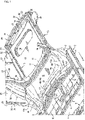
- FIG. 1 is a perspective top view illustrating the lower vehicle-body structure
- FIG. 2 is a cross-sectional view of a main part illustrating the vehicle-body structure of FIG. 1 taken along the vehicle front-rear direction at the center thereof in the vehicle width direction
- FIG. 3 is a cross-sectional view of a main part illustrating the vehicle-body structure of FIG. 1 taken along the vehicle width direction at a floor panel thick plate portion and a protruding portion
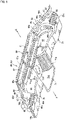
- FIG. 4 is a perspective plan view of the main part in FIG. 1
- FIG. 5 is a perspective view of a cross member including the floor panel thick plate portion and the protruding portion
- FIG. 1 is a perspective top view illustrating the lower vehicle-body structure
- FIG. 2 is a cross-sectional view of a main part illustrating the vehicle-body structure of FIG. 1 taken along the vehicle front-rear direction at the center thereof in the vehicle width direction
- FIG. 3 is a cross-sectional view of a main part illustrating the vehicle-body structure
- FIG. 6 is a perspective view of the cross member in a state in which a cross member upper portion is removed from FIG. 5
- FIG. 7 is a perspective rear view of the cross member including the floor panel thick plate portion and the protruding portion
- FIG. 8 is an enlarged cross-sectional view of the main part in FIG. 2 .
- a front floor panel 1 that forms the floor surface of a vehicle interior is provided.
- side sills 2 serving as vehicle body strength members extending in the front-rear direction of the vehicle are provided.
- the side sills 2 each may include a side sill inner portion 3, a side sill reinforcement 4, and a side sill outer portion formed by an outer plate panel of a vehicle body, and have a side sill closed cross-section extending in the front-rear direction of the vehicle.
- a front-portion cross member 5 (so-called No. 2 cross member) that couples the left and right side sills 2 and 2 to each other by extending in the vehicle width direction is provided on the upper surface of the front floor panel 1 between the pair of left and right side sills 2 and 2, and a closed cross-section extending in the vehicle width direction is formed between the front-portion cross member 5 and the front floor panel 1.
- an intermediate cross member 6 (so-called No. 2.5 cross member) that couples the left and right side sills 2 and 2 to each other by extending in the vehicle width direction is provided on the rear side of the front-portion cross member 5 so as to be substantially parallel to the front-portion cross member 5, and a closed cross-section 7 extending in the vehicle width direction is formed between the intermediate cross member 6 and the upper surface of the front floor panel 1.
- a closed cross-section expanded member 8 is mounted on the upper surface of the center portion of the intermediate cross member 6 in the vehicle width direction, and an expanded closed cross-section 9 is formed between the closed cross-section expanded member 8 and the intermediate cross member 6.
- a kick-up portion 10 that rises upward and then extends to the rear side is provided on the rear end portion of the front floor panel 1.
- a rear seat pan 12 on which a rear seat is installed at a place above the rear seat pan 12 is provided between the kick-up portion 10 illustrated in FIG. 1 and a rear-portion cross member 11 (so-called No. 4 cross member) illustrated in FIG. 1 and FIG. 2 .
- a rear-end-portion cross member (so-called No. 4.5 cross member) (not shown) that couples a pair of left and right rear side frames 13 and 13 to each other by extending in the vehicle width direction is provided.
- the rear-end-portion cross member is provided so as to be substantially parallel to the rear-portion cross member 11.
- a rear floor 15 is formed from the rear-portion cross member 11 to a rear end portion 14, and a trunk recessed portion 16 projecting to the vehicle lower side is formed in the center of the rear portion of the rear floor 15 in vehicle width direction.
- the rear-portion cross member 11 (so-called No. 4 cross member) is particularly formed by a rear-portion cross member upper portion 17 (so-called No. 4 cross member upper portion) of which cross-section has a hat-shaped profile and a rear-portion cross member lower portion 18 (so-called No. 4 cross member lower portion) of which cross-section has an inverted hat-shaped profile, and the closed cross-sections 19 and 20 extending in the vehicle width direction are formed so as to overlap each other in the up-down direction between the rear-portion cross member upper portion 17 and the rear floor 15, and between the rear-portion cross member lower portion 18 and the rear floor 15.
- the vehicle of this embodiment is an electrically driven vehicle, and a battery unit 21 that supplies the power source to a motor for traveling and driving the vehicle is disposed below the rear seat pan 12 on the rear side of the front floor panel 1 and the kick-up portion 10 as illustrated in FIG. 2 .
- rear side frames 13 extending in the front-rear direction of the vehicle are connected and fixed to both of left and right side portions of the rear floor 15.
- the rear side frames 13 are provided so as to extend toward the vehicle front side from the rear end portion 14 to positions overlapping with the rear portions of the side sills 2.
- the rear-portion cross member 11 and the rear-end-portion cross member are provided across the pair of left and right rear side frames 13 and 13.
- the rear-end-portion cross member is joined and fixed, particularly welded, to the lower surface portion of the rear floor 15.
- crash cans 23 serving as load absorbing portions are mounted on the rear ends of the rear side frames 13 via setting plates and mounting plates 22, and a rear bumper beam portion 24 extending in the vehicle width direction is laterally bridged between the pair of left and right crash cans 23 and 23.
- the rear bumper beam portion 24 includes a bumper beam main body 25 of which cross-section is a sideways-hat-shaped profile, closing plates 26 that occlude the rear-portion open sides of the bumper beam main body 25, and a lower-side extending portion 27 that is joined and fixed, particularly welded, to the closing plates 26 and extends substantially downward across the entire width of the closing plate 26 in the vehicle width direction.
- the rear bumper beam portion 24 extends in the vehicle width direction along a rear bumper (not shown), and the rear bumper beam portion 24 and the crash cans 23 and 23 serving as load absorbing portions extending from both of left and right ends of the rear bumper beam portion 24 to the vehicle front side form a rear bumper reinforcement 28.
- the rear side frames 13 are obtained by extending both of the left and right side portions of the rear floor 15 to the vehicle front-rear direction so that the rear ends thereof are coupled to the front ends of the crash cans 23 and 23.
- a rear wheel well 31 formed by a rear wheel well inner portion 30 and a rear wheel well outer portion is provided on the vehicle-width-direction outer side of each of the rear side frames 13.
- a door opening 33 without a center pillar is formed by the side sill 2 extending in the lower portion in the vehicle front-rear direction, a quarter pillar 32 extending in the rear portion in the vehicle up-down direction, a roof side rail extending in the upper portion in the vehicle front-rear direction, a hinge pillar extending in the front portion in the vehicle up-down direction, and a front pillar that couples the front end of the roof side rail and the upper end of the hinge pillar to each other in a diagonal direction.
- the door opening 33 is formed so that a front door and a rear door each having a clamshell door structure are disposed.
- reference numeral 34 indicates a side panel inner portion
- reference numeral 35 indicates lower portion bracing members extending substantially upward from the rear-portion cross member 11, in detail, from both of the left and right side portions of the rear-portion cross member upper portion 17 along each rear wheel well inner portion
- reference numeral 36 indicates an upper portion bracing member further extending substantially upward from each of the lower portion bracing members 35 along the rear wheel well inner portion
- reference numeral 37 indicates a damper supporting portion
- reference numeral 38 indicates floor side panels formed so as to project from the rear portions of the rear side frames 13 toward the vehicle width direction outer side.
- reference numeral 39 indicates a floor frame, which is joined and fixed, particularly welded, to the lower portion of the front floor panel 1 and of which cross-section is an inverted hat-shaped profile.
- the kick-up portion 10 bridges both of the pair of left and right side sills 2 and 2 in the vehicle width direction between the front floor panel 1 and the rear seat pan 12 serving as the rear floor panel, and the kick-up portion 10 is formed so as to include a closed cross-section portion (see a cross member closed cross-section S1 illustrated in FIG. 2 ) by a cross member 40 (so-called No. 3 cross member) described below.
- the lower vehicle-body structure of the vehicle of this embodiment includes the intermediate cross member 6 (so-called No. 2.5 cross member) that is a first cross member disposed on the intermediate portion of the front floor panel 1 in the vehicle front-rear direction so as to serve as a bridge in the vehicle width direction, and the cross member 40 (so-called No. 3 cross member) that is a second cross member disposed so as to serve as a bridge in the vehicle width direction so that at least the center portion in the vehicle width direction is at a position higher than the upper surface of the intermediate cross member 6 in the kick-up portion 10 between the front floor panel 1 and the rear seat pan 12 serving as the rear floor panel.
- the intermediate cross member 6 that is a first cross member disposed on the intermediate portion of the front floor panel 1 in the vehicle front-rear direction so as to serve as a bridge in the vehicle width direction
- the cross member 40 (so-called No. 3 cross member) that is a second cross member disposed so as to serve as a bridge in the vehicle width direction so that at least the center
- the intermediate cross member 6 and the cross member 40 are vehicle body strength members that couple the pair of left and right side sills 2 and 2 to each other in the vehicle width direction.
- the battery unit 21 disposed to the rear end position of the front floor panel 1 is included.
- the battery unit 21 is disposed below the front floor panel 1 and the rear seat pan 12.
- thick plate portions 70 (in detail, the floor panel thick plate portions 70) serving as high-strength portions coupled to the pair of left and right side sills 2 and 2 are provided.
- the thick plate portion 70 is a high-strength portion for the front floor panel 1, and the plate thickness of the thick plate portion 70 is set to be greater than the plate thickness of the front floor panel 1.
- the thick plate portions 70 By providing the thick plate portions 70, the proof stress of the rear end portion of the front floor panel 1 against the side collision load is improved, and the interference of the cross member 40 of the kick-up portion 10 and the battery unit 21 is avoided.
- a protruding portion 71 coupled to substantially vertical walls (see a cross member upper-portion lower center left portion 52 and a cross member upper-portion lower center right portion 53 described below) of the kick-up portion 10 is formed.
- the protruding portion 71 is particularly integrally formed by an upper surface portion 71a, left and right side surface portions 71b and 71b, and a front surface portion 71c, and the lower side and the rear side thereof are formed to be opened.
- an opening portion 71d is formed in the upper surface portion 71a of the protruding portion 71, and a lid member 72 that removably covers the opening portion 71d is mounted on the upper surface portion 71a.
- the thick plate portions 70 and 70 on the rear end of the front floor panel 1 are formed so as to be separated into a left part and a right part at the protruding portion 71 provided in the center in the vehicle width direction.
- the cross member 40 (so-called No. 3 cross member) forming the kick-up portion 10 includes a cross member upper portion 50 illustrated in FIG. 5 and a cross member lower portion 60 illustrated in FIG. 6 , and has the cross member closed cross-section S1 extending in the vehicle width direction by the cross member upper portion 50 and the ross member lower portion 60 (see FIG. 2 ).
- the cross member upper portion 50 may include a cross member upper-portion upper center portion 51 located on the upper center portion in the vehicle width direction, the cross member upper-portion lower center left portion 52 and the cross member upper-portion lower center right portion 53 serving as a kick-up portion vertical center wall located on the left side and the right side of the lower portion of the cross member upper-portion upper center portion 51, a cross member upper-portion side portion 55 located on the vehicle-width-direction left side of the cross member upper-portion upper center portion 51 and the cross member upper-portion lower center left portion 52 and having a kick-up portion vertical side wall 54, a cross member upper-portion side portion 57 located on the vehicle-width-direction right side of the cross member upper-portion upper center portion 51 and the cross member upper-portion lower center right portion 53 and having a kick-up portion vertical side wall 56, a cross member reinforcement 58 joined and fixed, particularly welded, to the inner surface of the corner portion of the cross member upper-portion upper center portion 51, that is, the lower
- the center end portions of the cross member upper-portion lower center left portion 52 and the cross member upper-portion lower center right portion 53 in the vehicle width direction serving as the kick-up portion vertical center wall are joined and fixed, particularly welded, to each other, and the lower end portion of the cross member upper-portion upper center portion 51 is joined and fixed, particularly welded, to the rear surface of an upper end portion a of the cross member upper-portion lower center left portion 52 and the cross member upper-portion lower center right portion 53.
- a lower end bending portion b of the cross member upper-portion lower center left portion 52 and the cross member upper-portion lower center right portion 53 is bent along the protruding portion 71, and the lower surface of the lower end bending portion b of the cross member upper-portion lower center left portion 52 and the cross member upper-portion lower center right portion 53 is joined and fixed, particularly welded, to the protruding portion 71.
- the cross member lower portion 60 is obtained by integrally coupling a cross member lower-portion upper center portion 61 located on the upper center portion in the vehicle width direction, a cross member lower portion lower center portion 62 located on the lower portion of the cross member lower-portion upper center portion 61, a cross member lower-portion lower left portion 63 and a cross member lower-portion lower right portion 64 located on both of left and right sides of the cross member lower-portion lower center portion 62 in the vehicle width direction, a cross member lower-portion side portion 65 located on the vehicle-width-direction left side of the cross member lower-portion upper center portion 61 and the cross member lower-portion lower left portion 63, and a cross member lower-portion side portion 66 located on the vehicle-width-direction right side of the cross member lower-portion upper center portion 61 and the cross member lower-portion lower right portion 64.
- an upper end bending portion 61a of the cross member lower-portion upper center portion 61 is welded together with the front end portion of the rear seat pan 12 and the rear end portion of the cross member upper-portion upper center portion 51 so that the three pieces overlap each other
- a lower end bending portion 61b of the cross member lower-portion upper center portion 61 is welded together with the cross member upper-portion lower center left portion 52 and the cross member upper-portion lower center right portion 53 so that the three pieces overlap each other.
- the thick plate portions 70 and 70 formed so as to be separated into the left part and the right part are coupled to the protruding portion 71 via the cross member upper-portion lower center left portion 52 and the cross member upper-portion lower center right portion 53 serving as a thick-plate kick-up portion vertical center wall.
- a place of the protruding portion 71 in which the high-strength portion is interrupted by the protruding portion 71 is reinforced with use of the cross member upper-portion lower center left portion 52 and the cross member upper-portion lower center right portion 53 serving as the kick-up portion vertical center wall that is strong against the bending deformation in the up-down direction.
- bending portions 70a and 70a bending substantially upward are particularly integrally formed on the rear end portions of the left and right thick plate portions 70 and 70, and the bending portions 70a and 70a are joined and fixed, particularly welded, to the cross member upper-portion lower center left portion 52 and the cross member upper-portion lower center right portion 53 serving as the kick-up portion vertical center wall.
- the strength against a side collision is improved.
- cross member upper-portion lower center left portion 52 and the cross member upper-portion lower center right portion 53 serving as the kick-up portion vertical center wall that couples the left and right thick plate portions 70 and 70 to each other are formed by thick plates of which plate thickness is greater than the other kick-up portion vertical side walls 54 and 56.
- the kick-up portion vertical center wall (the cross member upper-portion lower center left portion 52 and the cross member upper-portion lower center right portion 53) that couples the left and right thick plate portions 70 and 70 to each other is coupled to the second cross member 40, in detail, the cross member upper-portion upper center portion 51 disposed above the kick-up portion vertical center wall.
- the bending portions 70a of the thick plate portions 70 are joined and fixed, particularly welded, to not only the kick-up portion vertical center wall but also to the kick-up portion vertical side walls 54 and 56.
- side bending portions 70b rising substantially upward are integrally formed on the outer end portions of the thick plate portions 70 in the vehicle width direction, and the side bending portions 70b are joined and fixed, particularly welded, to the side sill inner portions 3.
- both of the left and right sides of the kick-up portion 10 formed by the cross member 40 (so-called No. 3 cross member) in the vehicle width direction are bent down to the lower side from vehicle-width-direction inner side positions 13a, that is, the inner ends in front portions 13F of the rear side frames 13 toward the side sills 2 and are connected to the side sills 2.
- the upper surface of the cross member upper-portion upper center portion 51 is formed so as to be straight across the entire width thereof in the vehicle width direction.
- the portions of the cross member upper-portion side portions 55 and 57 on the vehicle-width-direction inner sides thereof are formed to be straight so as to be continuous with the cross member upper-portion upper center portion 51, and portions on the vehicle-width-direction outer sides than those portions are bent substantially downward toward the side sills 2 so that the inner sides are high and the outer sides are low.
- an inner-side bending portion 41 and an outer-side bending portion 42 are formed in a continuous manner (see FIG. 3 ).
- a deformation facilitating bead portion b1 projecting to the upper front direction and extending in the front-rear direction of the vehicle as a flexure facilitating portion for the side collision load may be formed in a section on the outer side than the inner-side bending portion 41 of the kick-up portion 10 and an outer side portion 21a of the battery unit 21 and on the inner side than a vehicle-width-direction inner side position 13a (that is, the inner end) of the rear side frame 13, or a section that is substantially the same as the inner end.
- the deformation facilitating bead portion b1 serving as the flexure facilitating portion on the outer side of the inner-side bending portion 41 bends as a bending starting point before the inner-side bending portion 41 of the kick-up portion 10.
- the protruding amount (so-called overhang) of the place on the vehicle-width-direction outer side of the deformation facilitating bead portion b1 is reduced, and the interference with the battery unit 21 is suppressed.
- FIG. 9 is a cross-sectional arrow view taken along line A-A in FIG. 8
- FIG. 10 is a cross-sectional arrow view taken along line B-B in FIG. 8 .
- the cross member closed cross-section S1 of the kick-up portion 10 has an expanded portion S2 in which both of left and right end portions in the vehicle width direction are expanded to the lower side with respect to the center thereof.
- hanging walls 65b and 66b extending substantially downward from halfway portions in the vehicle width direction facing the inner-side bending portion 41 in upper walls 65a and 66a are formed, bottom walls 65c and 66c extending from the lower ends of the hanging walls 65b and 66b in the vehicle width direction are formed, upper end walls 65d and 66d inclined in a shape of which inner side is high and outer side is low so as to each correspond to the inner-side bending portion 41 and the outer-side bending portion 42 are provided, substantially vertical walls 65e and 66e that integrally couple the walls 65a, 65b, 65c, and 65d to each other and 66a, 66b, 66c, and 66d to each other in the up-down direction are provided.
- the expanded portion S2 (in detail, the expanded closed cross-section) expanded to the lower side with respect to the cross member closed cross-section S1 on the center side thereof is formed.
- a second deformation facilitating bead portion is formed above the expanded portion S2.
- a plurality of second deformation facilitating bead portions b2, b3, b4, and b5 projecting to the upper front side are formed in positions corresponding to the outer-side bending portions 42 of the cross member upper-portion side portions 55 and 57.
- a plurality of second deformation facilitating bead portions b6, b7, and b8 projecting to the lower rear side are formed in positions corresponding to the outer-side bending portions 42 of the cross member lower-portion side portions 65 and 66.
- the expanded portion S2 easily collapses at the time of a side collision of the vehicle.
- tapered portions 59 of which front side is low and rear side is high serving as corner portions are formed between the kick-up portion vertical side walls 54 and 56 and upper walls 55a and 57a of the expanded portion S2 in the closed cross-section portion S1 of the cross member upper-portion side portions 55 and 57 so as to be continuous in the vehicle width direction.
- the deformation facilitating bead portion b1 and the second deformation facilitating bead portions b2 to b5 are formed in the tapered portions 59.
- corner portions 69 and 69 continuous in the vehicle width direction are formed between the substantially vertical walls 65e and 66e and the upper end walls 65d and 66d of the expanded portion S2 in the closed cross-section portion S1 of the cross member lower-portion side portions 65 and 66, and the second deformation facilitating bead portions b6, b7, and b8 are formed on the corner portions 69 and 69.
- the deformation facilitating bead portions b1 to b5 on the cross member upper portion 50 side are formed on the tapered portions 59 serving as the corner portions, and the second deformation facilitating bead portions b6 to b8 on the cross member lower portion 60 side are formed on the corner portions 69.
- the tapered portion 59 and the corner portion 69 that hardly deform even at the time of a side collision are made to easily collapse.
- third deformation facilitating bead portions b9 extending in the substantially front-rear direction of the vehicle are formed on front-end-portion upper walls 13c of the rear side frames 13.
- the upper walls of the rear side frames 13 parallelly move to the vehicle-width-direction inner side at the time of a side collision of the vehicle is suppressed by the upward bending deformation by the third deformation facilitating bead portions b9.
- the openings of opening portions 68 and 68 are formed in the substantially vertical walls 65e and 66e on the lower side in the extending direction to the vehicle front side of the third deformation facilitating bead portions b9 projecting substantially upward and particularly integrally formed with the front-end-portion upper wall 13c of the rear side frame 13.
- the substantially vertical walls 65e and 66e easily collapse at the time of a side collision of the vehicle at the opening portions 68 and 68.
- a plurality of the second deformation facilitating bead portions b6, b7, and b8 are formed, and the openings of the opening portions 68 and 68 are formed below an intermediate portion of the plurality of second deformation facilitating bead portions b6, b7, and b8 in the vehicle width direction, in detail, below the bead portion b7 located in the middle out of the bead portions b6 to b8 in the vehicle width direction.
- arrow F indicates the vehicle front side
- arrow R indicates the vehicle rear side
- arrow IN indicates the inner side in the vehicle width direction
- arrow OUT indicates the outer side in the vehicle width direction
- arrow UP indicates the vehicle upper side.
- a lower vehicle-body structure of a vehicle of this embodiment includes: a first cross member (the intermediate cross member 6 serving as a so-called No. 2.5 cross member) disposed on an intermediate portion of a front floor panel 1 in a vehicle front-rear direction so as to serve as a bridge in a vehicle width direction; a second cross member (the cross member 40 serving as a so-called No.
- cross member 3 cross member disposed in a kick-up portion 10 between the front floor panel 1 and a rear floor panel (rear seat pan 12) so as to serve as a bridge in the vehicle width direction at a position in which at least a center portion in the vehicle width direction is higher than the first cross member (intermediate cross member 6); and a battery unit 21 disposed below at least the front floor panel 1 to a rear end position of the front floor panel 1.
- a high-strength portion (thick plate portion 70) for the front floor panel 1 is formed on a rear end of the front floor panel 1 on a lower end portion of the kick-up portion 10, the high-strength portion being coupled to both of a pair of left and right side sills 2 and 2 (see FIG. 1 , FIG. 2 , and FIG. 5 ).
- the high-strength portion (thick plate portion 70) coupled to the left and right side sills 2 and 2 is formed on the rear end of the front floor panel 1 on the lower end portion of the kick-up portion 10, and hence the proof stress of the rear end portion of the front floor panel 1 against the side collision load can be improved.
- the interference between the second cross member 40 of the kick-up portion 10 and the battery unit 21 can be avoided.
- the high-strength portion is formed by the thick plate portion 70 (see FIG. 1 and FIG. 3 ).
- the high-strength portion can be easily formed by changing the plate thickness.
- a protruding portion 71 coupled to a substantially vertical wall of the kick-up portion 10 is formed in a center of a rear end portion of the front floor panel 1, the thick plate portion 70 on the rear end of the front floor panel 1 is formed so as to be separated into a left thick plate portion and a right thick plate portion at the protruding portion 71, and the thick plate portions 70 and 70 formed in the separated manner are coupled to each other via a kick-up portion vertical center wall (the cross member upper-portion lower center left portion 52 and the cross member upper-portion lower center right portion 53) that is a thicker plate than the protruding portion 71 (see FIG. 5 ).
- a kick-up portion vertical center wall the cross member upper-portion lower center left portion 52 and the cross member upper-portion lower center right portion 53
- a place of the protruding portion 71 in which the high-strength portion (thick plate portion 70) is interrupted by the protruding portion 71 (so-called tunnel portion) on the rear end of the front floor panel 1 can be easily reinforced with use of the kick-up portion vertical center wall (the cross member upper-portion lower center left portion 52 and the cross member upper-portion lower center right portion 53) that is strong in the up-down bending deformation.
- rear end portions of the thick plate portions 70 are particularly bent substantially upward so as to form bending portions 70a, and the bending portions 70a are joined and fixed, particularly welded, to the kick-up portion vertical center wall (the cross member upper-portion lower center left portion 52 and the cross member upper-portion lower center right portion 53) (see FIG. 5 ).
- the kick-up portion vertical center wall (the cross member upper-portion lower center left portion 52 and the cross member upper-portion lower center right portion 53) that couples the left and right thick plate portions 70 and 70 to each other is formed by a thick plate of which plate thickness is greater than a plate thickness of other kick-up portion vertical side walls 54 and 56 (see FIG. 5 ) .
- the strength of the kick-up portion vertical center wall (the cross member upper-portion lower center left portion 52 and the cross member upper-portion lower center right portion 53) can be easily improved by changing the plate thickness.
- the kick-up portion vertical center wall (the cross member upper-portion lower center left portion 52 and the cross member upper-portion lower center right portion 53) that couples the left and right thick plate portions 70 and 70 to each other is coupled to the second cross member 40 (in detail, the cross member upper-portion upper center portion 51) disposed above the kick-up portion vertical center wall (see FIG. 5 ).
- the kick-up portion vertical center walls (the cross member upper-portion lower center left portion 52 and the cross member upper-portion lower center right portion 53) are coupled to the second cross member 40 (in detail, the cross member upper-portion upper center portion 51), and hence the proof stress against a side collision can be further improved.
- the first cross member of the present invention corresponds to the intermediate cross member 6 (so-called No. 2.5 cross member) of this embodiment.
- the rear floor panel corresponds to the rear seat pan 12
- the second cross member corresponds to the cross member 40 (so-called No. 3 cross member)
- the high-strength portion corresponds to the thick plate portion 70
- the kick-up portion vertical center wall corresponds to the cross member upper-portion lower center left portion 52 and the cross member upper-portion lower center right portion 53.
- the present invention is not only limited to the configurations of the abovementioned embodiment.
- the kick-up portion vertical center wall is separated into two left and right parts, that is, the cross member upper-portion lower center left portion 52 and the cross member upper-portion lower center right portion 53 is exemplified, but the structure may be a structure that is not separated into the left part and the right part.
- the present invention is useful for a lower vehicle-body structure of a vehicle including: a first cross member disposed on an intermediate portion of a front floor panel in a vehicle front-rear direction so as to serve as a bridge in a vehicle width direction; a second cross member disposed in a kick-up portion between the front floor panel and a rear floor panel so as to serve as a bridge in the vehicle width direction at a position in which at least a center portion in the vehicle width direction is higher than the first cross member; and a battery unit disposed below at least the front floor panel to a rear end position of the front floor panel.
Landscapes
- Engineering & Computer Science (AREA)
- Chemical & Material Sciences (AREA)
- Combustion & Propulsion (AREA)
- Transportation (AREA)
- Mechanical Engineering (AREA)
- Body Structure For Vehicles (AREA)
- Arrangement Or Mounting Of Propulsion Units For Vehicles (AREA)
Claims (8)
- Untere Fahrzeugaufbaustruktur eines Fahrzeugs, umfassend:ein erstes Querglied (6), das an einem Zwischenabschnitt eines vorderen Bodenblechs (1) in einer Fahrzeug-Front-Heck-Richtung angeordnet ist, um als eine Brücke in einer Fahrzeugbreitenrichtung zu dienen;ein zweites Querglied (40), das in einem gekröpften bzw. hochgezogenen Abschnitt (10) zwischen dem vorderen Bodenblech (1) und einem hinteren Bodenblech (12) angeordnet ist, um als eine Brücke in der Fahrzeugbreitenrichtung an einer Position zu dienen, in der zumindest ein Mittelabschnitt in der Fahrzeugbreitenrichtung höher ist als das erste Querglied (6); undeine Batterieeinheit (21), die unterhalb zumindest des vorderen Bodenblechs (1) bis zu einer hinteren Endposition des vorderen Bodenblechs (1) angeordnet ist, wobei ein hochfester Abschnitt (70) für das vordere Bodenblech (1) an einem hinteren Ende des vorderen Bodenblechs (1) in einem unteren Endabschnitt des gekröpften bzw. hochgezogenen Abschnitts (10) gebildet ist, wobei der hochfeste Abschnitt (70) mit beiden eines Paars linker und rechter Seitenschweller (2) gekoppelt ist.
- Untere Fahrzeugaufbaustruktur des Fahrzeugs nach Anspruch 1, wobei der hochfeste Abschnitt durch einen dicken Plattenabschnitt (70) gebildet ist.
- Untere Fahrzeugaufbaustruktur des Fahrzeugs nach Anspruch 2, wobei:ein vorspringender Abschnitt (71), der mit einer im Wesentlichen vertikalen Wand des hochgezogenen Abschnitts (10) gekoppelt ist, in einer Mitte eines hinteren Endabschnitts der vorderen Bodenplatte (1) gebildet ist;der dicke Plattenabschnitt an dem hinteren Ende der vorderen Bodenplatte (1) so gebildet ist, dass er in einen linken dicken Plattenabschnitt und einen rechten dicken Plattenabschnitt an dem vorspringenden Abschnitt (71) separiert ist; unddie dicken Plattenabschnitte, die auf separierte Weise gebildet sind, miteinander über eine vertikale Mittelwand (52, 53) des hochgezogenen Abschnitts gekoppelt sind, die eine dickere Platte ist als der vorspringende Abschnitt (71).
- Untere Fahrzeugaufbaustruktur des Fahrzeugs nach Anspruch 3, wobei:hintere Endabschnitte der dicken Plattenabschnitte (70) im Wesentlichen nach oben gebogen sind, um Biegeabschnitte (70a) zu bilden; unddie Biegeabschnitte (70a) mit der vertikalen Mittelwand (52, 53) des hochgezogenen Abschnitts verbunden und daran befestigt sind.
- Untere Fahrzeugaufbaustruktur des Fahrzeugs nach Anspruch 3 oder 4, wobei die vertikale Mittelwand (52, 53) des hochgezogenen Abschnitts, die den linken und den rechten dicken Plattenabschnitt (70) miteinander koppelt, durch eine dicke Platte gebildet ist, deren Plattendicke größer ist als eine Plattendicke von anderen vertikalen Seitenwände (54, 56) des hochgezogenen Abschnitts.
- Untere Fahrzeugaufbaustruktur des Fahrzeugs nach einem der Ansprüche 3 bis 5, wobei die vertikale Mittelwand (52, 53) des hochgezogenen Abschnitts, die den linken und den rechten dicken Plattenabschnitt miteinander koppelt, mit dem zweiten Querglied (40) gekoppelt ist, das über der vertikalen Mittelwand (52, 53) des hochgezogenen Abschnitts angeordnet ist.
- Fahrzeugaufbaustruktur eines Fahrzeugs, umfassend die untere Fahrzeugaufbaustruktur nach einem der vorhergehenden Ansprüche.
- Fahrzeug, umfassend:
die untere Fahrzeugaufbaustruktur nach einem der Ansprüche 1 bis 6 oder die Fahrzeugaufbaustruktur nach Anspruch 7.
Applications Claiming Priority (1)
| Application Number | Priority Date | Filing Date | Title |
|---|---|---|---|
| JP2019107389A JP7318323B2 (ja) | 2019-06-07 | 2019-06-07 | 車両の下部車体構造 |
Publications (2)
| Publication Number | Publication Date |
|---|---|
| EP3747737A1 EP3747737A1 (de) | 2020-12-09 |
| EP3747737B1 true EP3747737B1 (de) | 2022-04-20 |
Family
ID=69804694
Family Applications (1)
| Application Number | Title | Priority Date | Filing Date |
|---|---|---|---|
| EP20162461.6A Active EP3747737B1 (de) | 2019-06-07 | 2020-03-11 | Untere fahrzeugkarosseriestruktur eines fahrzeugs, fahrzeugkarosseriestruktur eines fahrzeugs und fahrzeug |
Country Status (4)
| Country | Link |
|---|---|
| US (1) | US11192586B2 (de) |
| EP (1) | EP3747737B1 (de) |
| JP (1) | JP7318323B2 (de) |
| CN (1) | CN112124441B (de) |
Families Citing this family (12)
| Publication number | Priority date | Publication date | Assignee | Title |
|---|---|---|---|---|
| JP7275836B2 (ja) * | 2019-05-15 | 2023-05-18 | マツダ株式会社 | 電動車両の下部車体構造 |
| JP7338251B2 (ja) * | 2019-06-07 | 2023-09-05 | マツダ株式会社 | 電動車両の下部車体構造 |
| JP7316513B2 (ja) * | 2019-09-11 | 2023-07-28 | マツダ株式会社 | 車両の車体構造 |
| KR102829341B1 (ko) * | 2020-05-19 | 2025-07-03 | 현대자동차주식회사 | 전기차량용 차체 |
| KR20220085231A (ko) * | 2020-12-15 | 2022-06-22 | 현대자동차주식회사 | 후방 차체 구조 |
| KR20230028853A (ko) * | 2021-08-23 | 2023-03-03 | 현대자동차주식회사 | 차량의 하부 차체 |
| KR20230099253A (ko) * | 2021-12-27 | 2023-07-04 | 현대자동차주식회사 | 후방 차체 구조 |
| FR3132072B1 (fr) * | 2022-01-26 | 2026-01-02 | Psa Automobiles Sa | Pièce structurelle déformable en cas de choc latéral, pour un véhicule |
| JP2023165320A (ja) * | 2022-05-02 | 2023-11-15 | マツダ株式会社 | 車両の下部車体構造 |
| KR20240093092A (ko) * | 2022-12-15 | 2024-06-24 | 현대자동차주식회사 | 차량의 차체 |
| JP2024135975A (ja) * | 2023-03-23 | 2024-10-04 | 株式会社Subaru | 車体下部構造 |
| JP7585375B2 (ja) * | 2023-03-24 | 2024-11-18 | 本田技研工業株式会社 | 車両 |
Family Cites Families (38)
| Publication number | Priority date | Publication date | Assignee | Title |
|---|---|---|---|---|
| JP3132261B2 (ja) * | 1993-09-20 | 2001-02-05 | 日産自動車株式会社 | 車体フロア構造 |
| JP3604085B2 (ja) * | 2001-06-05 | 2004-12-22 | 本田技研工業株式会社 | 車体構造 |
| US7331611B2 (en) * | 2004-06-30 | 2008-02-19 | Mazda Motor Corporation | Underbody structure of vehicle |
| JP4747812B2 (ja) * | 2005-12-01 | 2011-08-17 | マツダ株式会社 | 車両の下部車体構造 |
| KR100916389B1 (ko) * | 2007-09-03 | 2009-09-11 | 현대자동차주식회사 | 플로어 킥업부 보강을 위한 연료전지 차량용 어퍼 보디구조 |
| JP5098544B2 (ja) * | 2007-09-28 | 2012-12-12 | 三菱自動車工業株式会社 | バッテリユニット |
| JP5045340B2 (ja) | 2007-09-28 | 2012-10-10 | 三菱自動車工業株式会社 | 電気自動車 |
| US8292356B2 (en) * | 2009-03-17 | 2012-10-23 | Mazda Motor Corporation | Lower vehicle-body structure of vehicle |
| JP5202571B2 (ja) * | 2010-05-06 | 2013-06-05 | 本田技研工業株式会社 | 自動車のフロア構造 |
| FR2962964B1 (fr) * | 2010-07-23 | 2014-03-21 | Renault Sa | Chassis avec plancher arriere rehausse et procede d'assemblage. |
| JP5648421B2 (ja) * | 2010-10-26 | 2015-01-07 | マツダ株式会社 | 電動車両のバッテリ搭載構造 |
| WO2012086297A1 (ja) * | 2010-12-24 | 2012-06-28 | 本田技研工業株式会社 | 自動車の車体構造 |
| US8585131B2 (en) * | 2011-01-05 | 2013-11-19 | Tesla Motors, Inc. | Rear vehicle torque box |
| JP5799747B2 (ja) * | 2011-10-21 | 2015-10-28 | マツダ株式会社 | 車体のフロアパネル構造およびその設計方法 |
| JP6384257B2 (ja) * | 2014-10-14 | 2018-09-05 | 三菱自動車工業株式会社 | 車両フロア構造 |
| JP6187487B2 (ja) * | 2015-01-21 | 2017-08-30 | マツダ株式会社 | 車両の下部車体構造 |
| US9789907B2 (en) * | 2015-07-27 | 2017-10-17 | Ford Global Technologies, Llc | Method and apparatus for reinforcing a vehicle floor pan to prevent separation in a side impact |
| JP6434888B2 (ja) * | 2015-10-27 | 2018-12-05 | 本田技研工業株式会社 | 車体構造 |
| JP6519565B2 (ja) * | 2016-10-11 | 2019-05-29 | トヨタ自動車株式会社 | フロアパネル |
| JP6977307B2 (ja) * | 2017-04-28 | 2021-12-08 | トヨタ自動車株式会社 | 車両下部構造 |
| US11241948B2 (en) * | 2017-05-08 | 2022-02-08 | Mazda Motor Corporation | Rear body structure for vehicles |
| EP3608208B1 (de) * | 2017-05-08 | 2022-02-09 | Mazda Motor Corporation | Heckkarosseriestruktur für fahrzeuge |
| KR102375169B1 (ko) * | 2017-06-28 | 2022-03-16 | 현대자동차주식회사 | 전기자동차용 차체 플로어 구조 |
| US11312205B2 (en) * | 2017-07-06 | 2022-04-26 | Honda Motor Co., Ltd. | Vehicle |
| JP6597724B2 (ja) * | 2017-07-06 | 2019-10-30 | マツダ株式会社 | 自動車の下部車体構造 |
| JP6597723B2 (ja) * | 2017-07-06 | 2019-10-30 | マツダ株式会社 | 自動車の下部車体構造 |
| JP6977361B2 (ja) * | 2017-07-24 | 2021-12-08 | スズキ株式会社 | 車両下部構造 |
| JP6870588B2 (ja) * | 2017-11-16 | 2021-05-12 | トヨタ自動車株式会社 | 車両後部構造 |
| JP7124719B2 (ja) * | 2019-01-11 | 2022-08-24 | トヨタ自動車株式会社 | 車両下部構造 |
| JP7024748B2 (ja) * | 2019-02-27 | 2022-02-24 | マツダ株式会社 | 車両の後部車体構造 |
| JP7188183B2 (ja) * | 2019-02-27 | 2022-12-13 | マツダ株式会社 | 車両の後部車体構造 |
| JP7331448B2 (ja) * | 2019-05-15 | 2023-08-23 | マツダ株式会社 | 電動車両の下部車体構造 |
| CN111942481B (zh) * | 2019-05-15 | 2022-10-28 | 马自达汽车株式会社 | 车辆的下部车体构造 |
| CN111942480B (zh) * | 2019-05-15 | 2022-11-22 | 马自达汽车株式会社 | 电动车辆的下部车体构造 |
| US11186158B2 (en) * | 2019-05-30 | 2021-11-30 | Mazda Motor Corporation | Battery unit mounting structure of electric vehicle |
| US11165119B2 (en) * | 2019-05-30 | 2021-11-02 | Mazda Motor Corporation | Battery unit mounting structure of electric vehicle |
| JP7419678B2 (ja) * | 2019-06-05 | 2024-01-23 | マツダ株式会社 | 上部車体構造 |
| JP7408927B2 (ja) * | 2019-06-07 | 2024-01-09 | マツダ株式会社 | 車両の後部車体構造 |
-
2019
- 2019-06-07 JP JP2019107389A patent/JP7318323B2/ja active Active
-
2020
- 2020-03-11 EP EP20162461.6A patent/EP3747737B1/de active Active
- 2020-03-17 US US16/821,820 patent/US11192586B2/en active Active
- 2020-03-20 CN CN202010199377.XA patent/CN112124441B/zh active Active
Also Published As
| Publication number | Publication date |
|---|---|
| JP2020199844A (ja) | 2020-12-17 |
| JP7318323B2 (ja) | 2023-08-01 |
| US11192586B2 (en) | 2021-12-07 |
| US20200385056A1 (en) | 2020-12-10 |
| EP3747737A1 (de) | 2020-12-09 |
| CN112124441B (zh) | 2022-11-22 |
| CN112124441A (zh) | 2020-12-25 |
Similar Documents
| Publication | Publication Date | Title |
|---|---|---|
| EP3747737B1 (de) | Untere fahrzeugkarosseriestruktur eines fahrzeugs, fahrzeugkarosseriestruktur eines fahrzeugs und fahrzeug | |
| EP3747738B1 (de) | Untere fahrzeugkarosseriestruktur eines elektrofahrzeugs, fahrzeugkarosseriestruktur eines elektrofahrzeugs und elektrofahrzeug | |
| US11192593B2 (en) | Vehicle body structure of vehicle | |
| CN102292255B (zh) | 车辆侧部结合部结构 | |
| CN102470899B (zh) | 汽车的上部车身构造 | |
| EP3613657B1 (de) | Frontkarosseriestruktur eines fahrzeugs und verfahren zur bereitstellung oder verstärkung davon | |
| CN111791955B (zh) | 车辆的侧部车身结构 | |
| CN109305225B (zh) | 车辆的侧部车身结构 | |
| EP3712042B1 (de) | Karosseriestruktur eines fahrzeuges | |
| JP2024026467A (ja) | 車両下部構造 | |
| CN111591350B (zh) | 车辆的后部车身结构 | |
| JP2019131007A (ja) | 車体後部構造 | |
| JP7292605B2 (ja) | 車両の側部車体構造 | |
| JP2016002836A (ja) | 自動車の後部車体構造 | |
| JP4894629B2 (ja) | 自動車のロッカー補強構造 | |
| JP2021116036A (ja) | 車両の後部車体構造 | |
| US11142252B2 (en) | Upper vehicle-body structure | |
| JP2003095141A (ja) | 車両の下部車体構造 | |
| US11420682B2 (en) | Vehicle-body structure of vehicle | |
| JP2023103538A (ja) | 車両下部フレーム構造 | |
| JPH0565397B2 (de) |
Legal Events
| Date | Code | Title | Description |
|---|---|---|---|
| PUAI | Public reference made under article 153(3) epc to a published international application that has entered the european phase |
Free format text: ORIGINAL CODE: 0009012 |
|
| STAA | Information on the status of an ep patent application or granted ep patent |
Free format text: STATUS: THE APPLICATION HAS BEEN PUBLISHED |
|
| AK | Designated contracting states |
Kind code of ref document: A1 Designated state(s): AL AT BE BG CH CY CZ DE DK EE ES FI FR GB GR HR HU IE IS IT LI LT LU LV MC MK MT NL NO PL PT RO RS SE SI SK SM TR |
|
| AX | Request for extension of the european patent |
Extension state: BA ME |
|
| STAA | Information on the status of an ep patent application or granted ep patent |
Free format text: STATUS: REQUEST FOR EXAMINATION WAS MADE |
|
| 17P | Request for examination filed |
Effective date: 20210506 |
|
| RBV | Designated contracting states (corrected) |
Designated state(s): AL AT BE BG CH CY CZ DE DK EE ES FI FR GB GR HR HU IE IS IT LI LT LU LV MC MK MT NL NO PL PT RO RS SE SI SK SM TR |
|
| RIC1 | Information provided on ipc code assigned before grant |
Ipc: B60K 1/04 20190101ALI20210916BHEP Ipc: B62D 25/20 20060101ALI20210916BHEP Ipc: B62D 21/15 20060101AFI20210916BHEP |
|
| GRAP | Despatch of communication of intention to grant a patent |
Free format text: ORIGINAL CODE: EPIDOSNIGR1 |
|
| STAA | Information on the status of an ep patent application or granted ep patent |
Free format text: STATUS: GRANT OF PATENT IS INTENDED |
|
| INTG | Intention to grant announced |
Effective date: 20211110 |
|
| GRAS | Grant fee paid |
Free format text: ORIGINAL CODE: EPIDOSNIGR3 |
|
| GRAA | (expected) grant |
Free format text: ORIGINAL CODE: 0009210 |
|
| STAA | Information on the status of an ep patent application or granted ep patent |
Free format text: STATUS: THE PATENT HAS BEEN GRANTED |
|
| AK | Designated contracting states |
Kind code of ref document: B1 Designated state(s): AL AT BE BG CH CY CZ DE DK EE ES FI FR GB GR HR HU IE IS IT LI LT LU LV MC MK MT NL NO PL PT RO RS SE SI SK SM TR |
|
| REG | Reference to a national code |
Ref country code: GB Ref legal event code: FG4D |
|
| REG | Reference to a national code |
Ref country code: CH Ref legal event code: EP |
|
| REG | Reference to a national code |
Ref country code: IE Ref legal event code: FG4D |
|
| REG | Reference to a national code |
Ref country code: DE Ref legal event code: R096 Ref document number: 602020002707 Country of ref document: DE |
|
| REG | Reference to a national code |
Ref country code: AT Ref legal event code: REF Ref document number: 1484971 Country of ref document: AT Kind code of ref document: T Effective date: 20220515 |
|
| REG | Reference to a national code |
Ref country code: LT Ref legal event code: MG9D |
|
| REG | Reference to a national code |
Ref country code: NL Ref legal event code: MP Effective date: 20220420 |
|
| REG | Reference to a national code |
Ref country code: AT Ref legal event code: MK05 Ref document number: 1484971 Country of ref document: AT Kind code of ref document: T Effective date: 20220420 |
|
| PG25 | Lapsed in a contracting state [announced via postgrant information from national office to epo] |
Ref country code: NL Free format text: LAPSE BECAUSE OF FAILURE TO SUBMIT A TRANSLATION OF THE DESCRIPTION OR TO PAY THE FEE WITHIN THE PRESCRIBED TIME-LIMIT Effective date: 20220420 |
|
| PG25 | Lapsed in a contracting state [announced via postgrant information from national office to epo] |
Ref country code: SE Free format text: LAPSE BECAUSE OF FAILURE TO SUBMIT A TRANSLATION OF THE DESCRIPTION OR TO PAY THE FEE WITHIN THE PRESCRIBED TIME-LIMIT Effective date: 20220420 Ref country code: PT Free format text: LAPSE BECAUSE OF FAILURE TO SUBMIT A TRANSLATION OF THE DESCRIPTION OR TO PAY THE FEE WITHIN THE PRESCRIBED TIME-LIMIT Effective date: 20220822 Ref country code: NO Free format text: LAPSE BECAUSE OF FAILURE TO SUBMIT A TRANSLATION OF THE DESCRIPTION OR TO PAY THE FEE WITHIN THE PRESCRIBED TIME-LIMIT Effective date: 20220720 Ref country code: LT Free format text: LAPSE BECAUSE OF FAILURE TO SUBMIT A TRANSLATION OF THE DESCRIPTION OR TO PAY THE FEE WITHIN THE PRESCRIBED TIME-LIMIT Effective date: 20220420 Ref country code: HR Free format text: LAPSE BECAUSE OF FAILURE TO SUBMIT A TRANSLATION OF THE DESCRIPTION OR TO PAY THE FEE WITHIN THE PRESCRIBED TIME-LIMIT Effective date: 20220420 Ref country code: GR Free format text: LAPSE BECAUSE OF FAILURE TO SUBMIT A TRANSLATION OF THE DESCRIPTION OR TO PAY THE FEE WITHIN THE PRESCRIBED TIME-LIMIT Effective date: 20220721 Ref country code: FI Free format text: LAPSE BECAUSE OF FAILURE TO SUBMIT A TRANSLATION OF THE DESCRIPTION OR TO PAY THE FEE WITHIN THE PRESCRIBED TIME-LIMIT Effective date: 20220420 Ref country code: ES Free format text: LAPSE BECAUSE OF FAILURE TO SUBMIT A TRANSLATION OF THE DESCRIPTION OR TO PAY THE FEE WITHIN THE PRESCRIBED TIME-LIMIT Effective date: 20220420 Ref country code: BG Free format text: LAPSE BECAUSE OF FAILURE TO SUBMIT A TRANSLATION OF THE DESCRIPTION OR TO PAY THE FEE WITHIN THE PRESCRIBED TIME-LIMIT Effective date: 20220720 Ref country code: AT Free format text: LAPSE BECAUSE OF FAILURE TO SUBMIT A TRANSLATION OF THE DESCRIPTION OR TO PAY THE FEE WITHIN THE PRESCRIBED TIME-LIMIT Effective date: 20220420 |
|
| PG25 | Lapsed in a contracting state [announced via postgrant information from national office to epo] |
Ref country code: RS Free format text: LAPSE BECAUSE OF FAILURE TO SUBMIT A TRANSLATION OF THE DESCRIPTION OR TO PAY THE FEE WITHIN THE PRESCRIBED TIME-LIMIT Effective date: 20220420 Ref country code: PL Free format text: LAPSE BECAUSE OF FAILURE TO SUBMIT A TRANSLATION OF THE DESCRIPTION OR TO PAY THE FEE WITHIN THE PRESCRIBED TIME-LIMIT Effective date: 20220420 Ref country code: LV Free format text: LAPSE BECAUSE OF FAILURE TO SUBMIT A TRANSLATION OF THE DESCRIPTION OR TO PAY THE FEE WITHIN THE PRESCRIBED TIME-LIMIT Effective date: 20220420 Ref country code: IS Free format text: LAPSE BECAUSE OF FAILURE TO SUBMIT A TRANSLATION OF THE DESCRIPTION OR TO PAY THE FEE WITHIN THE PRESCRIBED TIME-LIMIT Effective date: 20220820 |
|
| REG | Reference to a national code |
Ref country code: DE Ref legal event code: R097 Ref document number: 602020002707 Country of ref document: DE |
|
| PG25 | Lapsed in a contracting state [announced via postgrant information from national office to epo] |
Ref country code: SM Free format text: LAPSE BECAUSE OF FAILURE TO SUBMIT A TRANSLATION OF THE DESCRIPTION OR TO PAY THE FEE WITHIN THE PRESCRIBED TIME-LIMIT Effective date: 20220420 Ref country code: SK Free format text: LAPSE BECAUSE OF FAILURE TO SUBMIT A TRANSLATION OF THE DESCRIPTION OR TO PAY THE FEE WITHIN THE PRESCRIBED TIME-LIMIT Effective date: 20220420 Ref country code: RO Free format text: LAPSE BECAUSE OF FAILURE TO SUBMIT A TRANSLATION OF THE DESCRIPTION OR TO PAY THE FEE WITHIN THE PRESCRIBED TIME-LIMIT Effective date: 20220420 Ref country code: EE Free format text: LAPSE BECAUSE OF FAILURE TO SUBMIT A TRANSLATION OF THE DESCRIPTION OR TO PAY THE FEE WITHIN THE PRESCRIBED TIME-LIMIT Effective date: 20220420 Ref country code: DK Free format text: LAPSE BECAUSE OF FAILURE TO SUBMIT A TRANSLATION OF THE DESCRIPTION OR TO PAY THE FEE WITHIN THE PRESCRIBED TIME-LIMIT Effective date: 20220420 Ref country code: CZ Free format text: LAPSE BECAUSE OF FAILURE TO SUBMIT A TRANSLATION OF THE DESCRIPTION OR TO PAY THE FEE WITHIN THE PRESCRIBED TIME-LIMIT Effective date: 20220420 |
|
| PLBE | No opposition filed within time limit |
Free format text: ORIGINAL CODE: 0009261 |
|
| STAA | Information on the status of an ep patent application or granted ep patent |
Free format text: STATUS: NO OPPOSITION FILED WITHIN TIME LIMIT |
|
| 26N | No opposition filed |
Effective date: 20230123 |
|
| PG25 | Lapsed in a contracting state [announced via postgrant information from national office to epo] |
Ref country code: AL Free format text: LAPSE BECAUSE OF FAILURE TO SUBMIT A TRANSLATION OF THE DESCRIPTION OR TO PAY THE FEE WITHIN THE PRESCRIBED TIME-LIMIT Effective date: 20220420 |
|
| PG25 | Lapsed in a contracting state [announced via postgrant information from national office to epo] |
Ref country code: SI Free format text: LAPSE BECAUSE OF FAILURE TO SUBMIT A TRANSLATION OF THE DESCRIPTION OR TO PAY THE FEE WITHIN THE PRESCRIBED TIME-LIMIT Effective date: 20220420 |
|
| PG25 | Lapsed in a contracting state [announced via postgrant information from national office to epo] |
Ref country code: MC Free format text: LAPSE BECAUSE OF FAILURE TO SUBMIT A TRANSLATION OF THE DESCRIPTION OR TO PAY THE FEE WITHIN THE PRESCRIBED TIME-LIMIT Effective date: 20220420 |
|
| REG | Reference to a national code |
Ref country code: CH Ref legal event code: PL |
|
| REG | Reference to a national code |
Ref country code: BE Ref legal event code: MM Effective date: 20230331 |
|
| PG25 | Lapsed in a contracting state [announced via postgrant information from national office to epo] |
Ref country code: LU Free format text: LAPSE BECAUSE OF NON-PAYMENT OF DUE FEES Effective date: 20230311 |
|
| REG | Reference to a national code |
Ref country code: IE Ref legal event code: MM4A |
|
| PG25 | Lapsed in a contracting state [announced via postgrant information from national office to epo] |
Ref country code: LI Free format text: LAPSE BECAUSE OF NON-PAYMENT OF DUE FEES Effective date: 20230331 Ref country code: IT Free format text: LAPSE BECAUSE OF FAILURE TO SUBMIT A TRANSLATION OF THE DESCRIPTION OR TO PAY THE FEE WITHIN THE PRESCRIBED TIME-LIMIT Effective date: 20220420 Ref country code: IE Free format text: LAPSE BECAUSE OF NON-PAYMENT OF DUE FEES Effective date: 20230311 Ref country code: FR Free format text: LAPSE BECAUSE OF NON-PAYMENT OF DUE FEES Effective date: 20230331 Ref country code: CH Free format text: LAPSE BECAUSE OF NON-PAYMENT OF DUE FEES Effective date: 20230331 |
|
| PG25 | Lapsed in a contracting state [announced via postgrant information from national office to epo] |
Ref country code: BE Free format text: LAPSE BECAUSE OF NON-PAYMENT OF DUE FEES Effective date: 20230331 |
|
| PG25 | Lapsed in a contracting state [announced via postgrant information from national office to epo] |
Ref country code: BG Free format text: LAPSE BECAUSE OF FAILURE TO SUBMIT A TRANSLATION OF THE DESCRIPTION OR TO PAY THE FEE WITHIN THE PRESCRIBED TIME-LIMIT Effective date: 20220420 |
|
| GBPC | Gb: european patent ceased through non-payment of renewal fee |
Effective date: 20240311 |
|
| PG25 | Lapsed in a contracting state [announced via postgrant information from national office to epo] |
Ref country code: BG Free format text: LAPSE BECAUSE OF FAILURE TO SUBMIT A TRANSLATION OF THE DESCRIPTION OR TO PAY THE FEE WITHIN THE PRESCRIBED TIME-LIMIT Effective date: 20220420 |
|
| PG25 | Lapsed in a contracting state [announced via postgrant information from national office to epo] |
Ref country code: GB Free format text: LAPSE BECAUSE OF NON-PAYMENT OF DUE FEES Effective date: 20240311 |
|
| PG25 | Lapsed in a contracting state [announced via postgrant information from national office to epo] |
Ref country code: GB Free format text: LAPSE BECAUSE OF NON-PAYMENT OF DUE FEES Effective date: 20240311 |
|
| PG25 | Lapsed in a contracting state [announced via postgrant information from national office to epo] |
Ref country code: CY Free format text: LAPSE BECAUSE OF FAILURE TO SUBMIT A TRANSLATION OF THE DESCRIPTION OR TO PAY THE FEE WITHIN THE PRESCRIBED TIME-LIMIT; INVALID AB INITIO Effective date: 20200311 |
|
| PG25 | Lapsed in a contracting state [announced via postgrant information from national office to epo] |
Ref country code: HU Free format text: LAPSE BECAUSE OF FAILURE TO SUBMIT A TRANSLATION OF THE DESCRIPTION OR TO PAY THE FEE WITHIN THE PRESCRIBED TIME-LIMIT; INVALID AB INITIO Effective date: 20200311 |
|
| PG25 | Lapsed in a contracting state [announced via postgrant information from national office to epo] |
Ref country code: TR Free format text: LAPSE BECAUSE OF FAILURE TO SUBMIT A TRANSLATION OF THE DESCRIPTION OR TO PAY THE FEE WITHIN THE PRESCRIBED TIME-LIMIT Effective date: 20220420 |
|
| PGFP | Annual fee paid to national office [announced via postgrant information from national office to epo] |
Ref country code: DE Payment date: 20260128 Year of fee payment: 7 |