EP3748100A1 - System zum verbinden einer warenbahn mit einer wickelwelle - Google Patents
System zum verbinden einer warenbahn mit einer wickelwelle Download PDFInfo
- Publication number
- EP3748100A1 EP3748100A1 EP20174507.2A EP20174507A EP3748100A1 EP 3748100 A1 EP3748100 A1 EP 3748100A1 EP 20174507 A EP20174507 A EP 20174507A EP 3748100 A1 EP3748100 A1 EP 3748100A1
- Authority
- EP
- European Patent Office
- Prior art keywords
- recess
- winding shaft
- web
- section
- rod
- Prior art date
- Legal status (The legal status is an assumption and is not a legal conclusion. Google has not performed a legal analysis and makes no representation as to the accuracy of the status listed.)
- Granted
Links
Images


Classifications
-
- E—FIXED CONSTRUCTIONS
- E04—BUILDING
- E04F—FINISHING WORK ON BUILDINGS, e.g. STAIRS, FLOORS
- E04F10/00—Sunshades, e.g. Florentine blinds or jalousies; Outside screens; Awnings or baldachins
- E04F10/02—Sunshades, e.g. Florentine blinds or jalousies; Outside screens; Awnings or baldachins of flexible canopy materials, e.g. canvas ; Baldachins
- E04F10/06—Sunshades, e.g. Florentine blinds or jalousies; Outside screens; Awnings or baldachins of flexible canopy materials, e.g. canvas ; Baldachins comprising a roller-blind with means for holding the end away from a building
- E04F10/0633—Arrangements for fastening the flexible canopy material to the supporting structure
-
- E—FIXED CONSTRUCTIONS
- E06—DOORS, WINDOWS, SHUTTERS, OR ROLLER BLINDS IN GENERAL; LADDERS
- E06B—FIXED OR MOVABLE CLOSURES FOR OPENINGS IN BUILDINGS, VEHICLES, FENCES OR LIKE ENCLOSURES IN GENERAL, e.g. DOORS, WINDOWS, BLINDS, GATES
- E06B9/00—Screening or protective devices for wall or similar openings, with or without operating or securing mechanisms; Closures of similar construction
- E06B9/24—Screens or other constructions affording protection against light, especially against sunshine; Similar screens for privacy or appearance; Slat blinds
- E06B9/40—Roller blinds
- E06B9/42—Parts or details of roller blinds, e.g. suspension devices, blind boxes
- E06B9/44—Rollers therefor; Fastening roller blinds to rollers
- E06B9/46—Rollers therefor; Fastening roller blinds to rollers by clamping bars
Definitions
- the subject of the invention is a system for connecting a web of material to a winding shaft according to the preamble of patent claim 1.
- Awnings as sun and / or rain protection comprise a web of material that can be wound up on a winding shaft in order to be able to protect it and stow it in a small space when not in use.
- a rod is inserted into a hemstitch in the edge of the fabric to be connected to the winding shaft, thereby forming a welt bead.
- a welt flap can also be attached to the edge of the fabric, for example sewn on.
- an axially extending recess is attached to the latter under the jacket surface as a welt rail, into which the welt can be inserted.
- the recess is approximately circular in cross section and the recess is only connected to the surface of the winding shaft at a narrow point, so that after the material web is inserted with the piping, the material web is held in the axial direction.
- Such connections between the fabric web and the winding shaft are safe and relatively easy to handle.
- a disadvantage of such a connection is the effort involved in inserting the welt, since it can only be introduced into the winding shaft at the end and consequently the winding shaft must be exposed at its end for insertion.
- Another disadvantage is that the web of fabric, for example an awning fabric made of acrylic, which can at least have a thickness of 1 to 3 mm, is led out radially out of the recess on the winding shaft and thus the area after the first loop and further loopings when winding the awning, which lies over the slot of the recess, is slightly lifted off and consequently this area is defined by this bead on the awning when it is extended.
- an arrangement for connecting a web of material, in particular awning, to a winding shaft is also known.
- a recess is made in the winding shaft, the base of which is formed in the shape of a segment of a circular arc and which extends in cross section in an S-shape on the two side edges Areas are formed so that the slot in the jacket surface of the winding shaft has a smaller width than the base of the recess.
- the recess forms space for a bar that can be clicked into place through a groove that is essentially T-shaped in cross section, so that it does not protrude beyond the jacket surface of the winding shaft, but can reach under the protruding edge areas of the slot with its lateral edges.
- a groove is made on the underside of the bar so that the area of the bar outside the groove, which must be made of a relatively soft, flexible plastic material , when the rod is placed and simultaneously compressed, it can reject the recess or the slot over its entire length and so the width of the rod is shortened for a short time.
- the rod area swings away from the groove again outside the groove and thus holds the rod firmly within the recess.
- a bore running along its longitudinal edges is embedded in the rod and is connected to the surface of the rod by a slot.
- the rod cannot be securely held in it after it has been clipped into the recess in the winding shaft, because if an increased tensile force acts on the awning, especially if the recess on the winding shaft is not in the upper apex of the same, but comes to lie further down, the rod is bent and thereby the elastic holding area can be pulled out of the recess, since it is known that it must be designed to be pivotable on the rod for insertion.
- the connection between awning and rod is therefore very complex and, on the other hand, the anchoring of the rod after assembly on the winding shaft is not guaranteed in every position.
- a winding shaft is known in which an S-shaped holding area is attached along the edge of the awning, which must be connected to the winding shaft. This engages in a circular hole in the winding shaft that is connected to the surface through a slot.
- a secure hold of the awning is only guaranteed if the awning has already been wrapped around the winding shaft and over the S-shaped one The hook comes to rest and presses it radially onto the winding shaft. A secure hold is therefore not guaranteed.
- connection system makes it possible to arrange the connection area of the material web completely under the jacket surface of the winding shaft, so that there is no step-like transition on the surface of the winding shaft and after the first wrapping of the winding shaft by the material web, the area of the second winding layer coming to lie above the connection area the web is not pushed radially outwards, but comes to lie within the arcuate course of the jacket surface of the winding shaft.
- the transition from the first looping to the second is consequently stepless without the formation of a bead.
- This is achieved by a hanging profile rod which is connected on one side to the edge area of the web and which can be completely inserted into a recess under the surface of the winding shaft and fastened there so that it can be locked in place.
- the system has a very advantageous and time-saving effect, as the suspension profile bar with the fabric web is radially attached to the one installed in a door or window lintel Winding shaft brought up and can be hung and locked in a recess in the outer surface without tools. There is no axial displacement during use, as the suspension profile rod engages in the recess. It is therefore no longer necessary to dismantle the winding shaft in order to introduce the connecting element.
- the suspension profile bar can be connected directly to the edge area of the material web in a simple and cost-effective manner, in that the connection is made by ultrasonic welding or by gluing. In addition, there is no need to attach a seam to the edge of the web, but the cut edge can be attached to the hanging profile bar without any further treatment.
- a transition element can be attached in advance to the edge of the material web, which in turn is connected to the hanging profile bar.
- the transition element improves the smooth run-in of the material web from the recess into the outer surface of the winding shaft.
- the recess can be produced very easily on the winding shaft.
- the recess has a slot which is very wide in relation to its depth and which enables the insertion of the suspension profile rod in the radial direction and does not, as before, require dismantling of the winding shaft in order to be inserted axially.
- the hitherto necessarily to be formed on the web of material with a rod arranged therein to form a Keder bead as a fastening element on the winding shaft is omitted.
- the hanging profile bar can be attached directly to the cut, uncleaned web edge with little effort by gluing or ultrasonic welding.
- the uncleaned leading edge of the material web is connected to a connecting tape by welding or gluing.
- the connecting tape for its part, is also connected to the hanging profile bar by gluing or welding. This enables the suspension profile bar to be inserted completely into the slot-shaped recess and no parts protrude beyond the jacket surface of the winding shaft. If a connecting tape is also inserted between the material web and the hanging profile bar, a completely seamless connection between the winding shaft and the material web can be achieved.
- the suspension profile rod and the connecting tape which is preferably made of a softer material than the profile rod, can also be made in one piece, so that only one connection to the fabric edge has to be made. If an awning's web has to be replaced after years due to a defect, the web with the attached profile bar can be pushed out of the recess and replaced with a new or repaired web without dismantling the winding shaft.
- a system for connecting a web 3, for example the fabric for an awning, to a winding shaft 5 is designated by reference numeral 1.
- the winding shaft 5, which can be driven manually or electrically, has a circular cross section with a jacket surface 7.
- the winding shaft 5 is preferably made as an aluminum profile.
- a recess 9 formed under the jacket surface 7 can be seen, above which an axially extending slot 11 ( Fig. 6 ) is formed with a width b in the jacket surface 7.
- the width b of the slot 11 can extend in the circumferential direction up to the dimension of the radius r of the winding shaft 1.
- a significantly smaller opening width b can also be selected depending on the diameter of the winding shaft 5, a significantly smaller opening width b can also be selected.
- the cross-section of the recess 9 has the shape of a T-groove or, as shown in the figures, a flattened C lying on its back, the back 13 of which can be bent slightly radially convex outwards, i.e. approximately parallel to the missing area in the Jacket surface 7 above the slot 11.
- the recess 9 has an inner width B.
- the two transitions from the jacket surface 7 to the back 13 run roughly in the shape of semicircles directed towards one another (cf. Fig. 1,2 , 6th ).
- the recess 9 is used in the system to receive a suspension profile rod 17.
- the Suspension profile rod 17 has the shape of an upside-down T with a bottom surface 19, the convex curvature of which can correspond to the back 13 in the recess 9 on the winding shaft 5.
- a contact surface 21 opposite the bottom surface 19 on the body of the suspension profile bar 17 serves to receive and connect a connecting tape 23 or directly to the edge area of the web 3.
- the connecting tape 23 as part of the profiled bar 17 is used to attach the front edge area of the web 3 to the hook -Profile rod 17 to be permanently connected.
- the connecting tape 23 has in Figure 4 on the right-hand side on its radially outer surface, a shoulder 25, so that the surface of a web 3 fastened in the thinner area 23 ′ on the connecting tape 23 merges steplessly or steplessly into the outer surface 27 of the connecting tape 23.
- the connecting band 23 and a front edge of a web 3 fastened thereon consequently lie in a common convexly curved surface.
- the connecting tape 23 can at its left free end in Figure 4 have a greater wall thickness than in the subsequent section lying in contact with the suspension profile rod 17.
- connection between the suspension profile rod 17 and the connecting tape 23 can be made by gluing or, as shown in the example, by ultrasonic welding, through which an insignificant indentation in the weld area 29 is formed
- Connection tape 23 can arise and possibly also in the contact surface 21 of the hanging profile rod 17.
- the suspension profile bar 17 is designed in a step shape at both ends, so that the upper contact surface 21 is shorter than the lower base surface 19.
- the first step-shaped section 31 of the suspension profile rod 17 takes on the thicker end of the connecting tape 23 on the left side and is longer than the second step-shaped section 33 on the right side in the Figures 3 and 5 .
- the thickness c 1 of the suspension profile rod 17 following the first step-shaped section 31 is smaller than the thickness c 2 before the second step-shaped section 33.
- the surface 27 of the connecting strip 23 reaches the jacket surface 7 of the winding shaft 5 in a stepless manner.
- these are made of an ultrasonically weldable material or of materials that can be optimally and permanently glued to one another.
- the connecting band 23 is preferably made of a plastic that is more flexible, softer and more compressible than the harder and thus stiff material of the hanging profile rod 17.
- the hanging profile rod 17 and the connecting band 23 can also be made in one piece, for example by a Extrusion process or a two-component injection process, so that later gluing or welding of the two elements is no longer necessary.
- connection The mode of operation of the connection between the winding shaft 5 and the suspension profile bar 17 with the connecting tape 23 attached to it and the web of material 3 of the first embodiment attached to it is described below.
- a material web 3 for an awning has been cut / assembled, its front edge or the front edge region is connected to the shoulder 25 on the connecting tape 23 in abutment therewith.
- the connection can be made by gluing or by ultrasonic welding, which permanently connects the two materials, namely the web 3 and the connecting tape 23, to one another.
- the fabric web 3 prepared in this way with the connecting tape 23 attached to it is now connected to the hanging profile bar 17.
- This connection can also be made by gluing or ultrasonic welding.
- the suspension profile bar 17 could also be connected to the connecting tape 23 first and only then the web 3 could be attached to the connecting tape 23.
- the awning prepared in this way can now be mounted on the winding shaft 5, which is rotatably mounted in the lintel of a window or door opening or in a weatherproof housing, and is or motorized drive can be rotated. To do this, it is not necessary to detach the winding shaft 5 from its suspension and drive, but instead the suspension profile bar 17 with its stepped shoulder 31 located at the front, ie on the left side in the figures, is essentially at an acute angle to the jacket surface in the direction of the arrow F is inserted into the recess 9.
- the first step-shaped section 31 engages under the semicircular area 15 of the recess 9.
- the thickened end of the connecting tape 23 since it is preferably made of a softer material than the central area of the profile rod 17, can be pushed back or pushed back a little.
- the suspension profile rod 17 is pivoted in the direction of the arrow P (clockwise) and then comes with its bottom surface 19 in contact with the back 13 of the recess 9 ( compare Figure 1 ).
- the web 3 is pressed radially against the outer surface 7 of the winding shaft 5 and the suspension profile rod 17 or its second step-shaped section 33 is drawn into the circular arc-shaped edge area of the recess 9.
- the first step-shaped section 31 continues to remain radially held in the arcuate section of the recess 9 (left side).
- the clockwise insertion is also supported by the tension of the compressed soft end of the connecting tape 23.
- the hanging profile bar 17 is now, almost filling the recess 9, held in the recess 9 on both edges.
- the surface 27 of the connecting tape 23 and the outer one The surfaces of the web 3 lie in a seamlessly running, essentially circular path in the jacket surface 7 of the winding shaft 5.
- the suspension profile rod 17 ' is designed as a unit with the connecting band 23 "and can thus be produced in one piece from two components of different hardness and is referred to as a connecting element 35.
- the connecting element 35 comprises a first step-shaped section 31 and a second step-shaped section 33
- a resilient nose 37 is molded onto the first step-shaped section 31 and, on the opposite side above the second step-shaped section 33, a connecting band section 23 ', which is also made of a softer material than the central part of the connecting element 35 greater strength and above all produced higher rigidity than the nose 37 and the section 23 'of the connecting strip 23.
- the connecting element is produced by injection molding with two different plastic components.
- connection of the web 3 with the lower strength or thickness and preferably high elasticity having section of the connecting tape 23 'outside the shoulder 25, serves as a connection area of the connecting element 35 with the web 3.
- the connection is made either by gluing with an adhesive Mutual bonding by the action of heat or by ultrasonic welding.
- connection between the winding shaft 5 and the suspension profile bar 17 with the material web 3 of the second embodiment attached thereto is described below.
- the material web 3 has been cut / assembled, its front edge is placed on the shoulder 25 of the connection area 23 'and connected to the connection area 23' by an adhesive, a thermal fusion or by an ultrasonic welding.
- the connection of the web 3 with the connecting element 35 can preferably already in the premises of the manufacturer of the awning or at the place of use shortly before the attachment of the web 3 to the winding shaft 5.
- the web 3 fastened to the connecting element 35 is then, as in FIG Figure 2 of the first embodiment shown, on site, ie latched onto the winding shaft already attached to a building.
- the fitter introduces the first step-shaped section 31 on the suspension profile bar (17) at an acute angle to the surface of the jacket of the winding shaft 5 under the semicircular recess 15 in the recess 9 on the winding shaft 5.
- the elastic nose 37 which extends as a rib over the entire length of the connecting element 15 or over at least several partial lengths, now touches the jacket 7 of the winding shaft 5.
- the connecting element 35 moves clockwise by the force of the elastically tensioned nose 37 and its second step-shaped section 33 comes under the semicircular area of the recess 9 on the right-hand side. So that the suspension profile bar 17 is in the Recess 9 anchored. As soon as the winding shaft 5 is rotated counterclockwise in order to be able to wind up the web 3, the connecting element 35 is also moved up to the stop in the recess 9, unless the force of the nose 37 has already moved the connecting element 35 completely clockwise.
- an awning or the material web 3 has to be replaced in the event of damage, it can be removed from the winding shaft 5 in the reverse order without dismantling it.
Landscapes
- Engineering & Computer Science (AREA)
- Architecture (AREA)
- Structural Engineering (AREA)
- Civil Engineering (AREA)
- Building Awnings And Sunshades (AREA)
Abstract
Description
- Gegenstand der Erfindung ist ein System zum Verbinden einer Warenbahn mit einer Wickelwelle gemäss Oberbegriff des Patentanspruch 1.
- Markisen als Sonnen- und/oder Regenschutz umfassen eine Stoffbahn, die auf einer Wickelwelle aufwickelbar ist, um sie geschützt und auf kleinem Raum bei Nichtgebrauch stauen zu können. Üblicherweise wird in die mit der Wickelwelle zu verbindende Kante des Stoffs in einem Hohlsaum ein Stab eingelegt und dadurch ein Kederwulst gebildet. Alternativ kann auch eine Kederfahne an der Kante des Stoffs angebracht, z.B. aufgenäht werden. Zur Befestigung der Kante des Stoffs mit dem Kederwulst an der Wickelwelle ist an letzterer unter der Manteloberfläche eine axial verlaufende Ausnehmung als Kederschiene angebracht, in welche der Keder eingelegt werden kann. Meistens ist die Ausnehmung im Querschnitt etwa kreisrund und die Ausnehmung steht nur an einer schmalen Stelle mit der Oberfläche der Wickelwelle in Verbindung, so dass nach Einschieben der Stoffbahn mit dem Keder in axialer Richtung die Stoffbahn gehalten wird. Solche Verbindungen zwischen Stoffbahn und Wickelwelle sind sicher und verhältnismässig einfach zu handhaben.
- Nachteilig an einer solchen Verbindung ist der Aufwand zum Einführen des Keders, da dieser nur stirnseitig in die Wickelwelle eingeführt werden kann und folglich die Wickelwelle an deren Ende für das Einführen freigelegt werden muss. Ein weiterer Nachteil besteht darin, dass die Stoffbahn, beispielsweise ein Markisenstoff aus Acryl, der immerhin eine Dicke von 1 bis 3 mm aufweisen kann, radial aus der Ausnehmung an der Wickelwelle herausgeführt wird und dadurch nach der ersten Umschlingung und weiteren Umschlingungen beim Aufwickeln der Bereich der Markise, die über dem Schlitz der Ausnehmung liegt, leicht abgehoben wird und folglich dieser Bereich sich durch diesen Wulst auf der Markise, wenn sie ausgefahren ist, abzeichnet. Dies führt zu einem negativen Erscheinungsbild der Markise.
Wird die Markise bzw. deren Kante auf die Welle aufgeschraubt oder aufgenietet und durch einen Abdeckstab auf die Oberfläche der Welle gedrückt, so entsteht dasselbe negative Erscheinungsbild, da sich auch dieser Bereich auf der Markise ein- oder mehrmals abzeichnet. - Aus der
EP 3 431 678 A1 ist weiter eine Anordnung zum Verbinden einer Warenbahn, insbesondere Markise, mit einer Wickelwelle bekannt. In dieser Anordnung ist in der Wickelwelle eine Ausnehmung eingelassen, deren Basis kreisbogenabschnittförmig ausgebildet ist und an deren beiden Seitenkanten im Querschnitt S-förmig verlaufende Bereiche ausgebildet sind, sodass der Schlitz in der Manteloberfläche der Wickelwelle eine geringere Breite aufweist wie die Basis der Ausnehmung. Die Ausnehmung bildet für einen einklickbaren Stab durch eine im Wesentlichen im Querschnitt T-förmige Nut Raum, sodass dieser nicht über die Manteloberfläche der Wickelwelle hinausragt, jedoch mit seinen seitlichen Kanten die überstehenden Randbereiche des Schlitzes untergreifen kann. Um den Stab, an welchem die Markise befestigt wird, in die axial verlaufende Ausnehmung einsetzen zu können, ist an der Unterseite des Stabs eine Nut eingelassen, damit der ausserhalb der Nut liegende Bereich des Stabs, der aus einem verhältnismässig weichen biegsamen Kunststoffmaterial hergestellt sein muss, beim Auflegen und gleichzeitigen Zusammenpressen des Stabs auf seiner gesamten Länge auf die Ausnehmung bzw. den Schlitz zurückweisen kann und so die Breite des Stabs kurzfristig verkürzt wird. Nach dem radialen Einschieben des Stabs schwenkt der Stabbereich ausserhalb der Nut wieder von der Nut weg und hält so den Stab innerhalb der Ausnehmung fest. Weiter ist im Stab eine entlang dessen Längskanten verlaufende Bohrung eingelassen, die durch einen Schlitz mit der Oberfläche des Stabs verbunden ist. In diese Bohrung muss der Keder an einer Markise mühsam axial eingeschoben und so am Stab gehalten werden.
Diese Anordnung ermöglicht zwar eine versenkte Anordnung eines die Markise festhaltenden Stabs, jedoch ist einerseits das Verbinden der Markise mit dem Stab aufwendig, da diese über die gesamte Länge des Stabs in diesen eingeschoben werden muss. Dies kann bei Markisen von mehreren Metern Länge rein platzmässig und auch arbeitsmässig viel Aufwand benötigen. Im Weiteren kann andererseits der Stab, nachdem er in die Ausnehmung in der Wickelwelle eingeklipst ist, darin nicht sicher gehalten werden, denn, falls eine erhöhte Zugkraft auf die Markise einwirkt, vor allem wenn die Ausnehmung an der Wickelwelle nicht im oberen Scheitel derselben, sondern weiter unten zu liegen kommt, erfolgt ein Durchbiegen des Stabs und dadurch kann der elastische Haltebereich aus der Ausnehmung herausgezogen werden, da dieser bekanntlich für das Einführen schwenkbeweglich am Stab ausgebildet sein muss. Einerseits ist folglich die Verbindung zwischen Markise und Stab sehr aufwendig und andererseits ist die Verankerung des Stabs nach der Montage an der Wickelwelle nicht in jeder Position gewährleistet. - Weiter ist aus der
CH 698 032 - Weiter ist aus der
US 2006/0207731 eine Verbindungsanordnung zwischen einer Wickelwelle und der Kante einer Markise bekannt. An der Kante der Markise isst ein Halteelement befestigt, dessen Ende T-förmig ausgebildet ist und in eine entsprechende T-förmige Nut in der Wickelwelle eingreift. Eine solcherart ausgerüstete Markise kann nur axial in die Wickelwelle eingeführt werden. Dies bewirkt, dass für einen Wechsel der Markise, z.B. wenn diese beschädigt ist oder auch bei der Montage einer neuen Sonnenschutzanlage, die Wickelwelle aus deren Lagerung herausgehoben, dann die Markise, z.B. eine 6 m breite Markise, eingeführt werden muss und nachher die schwere Wickelwelle samt der nicht aufgewickelten Markise nach oben in die Lager für die Welle befördert werden muss. Eine solche Anordnung ist sehr zeitaufwendig während der Montage (axiales Einführen und Anheben der schweren Welle mit darauf befindlicher Markise und deren nachträgliche Montage an der Oberseite einer Fenster- oder Türöffnung). - Eine Aufgabe der vorliegenden Erfindung besteht nun darin, ein System zur Befestigung bzw. zur Verbindung der Kante einer textilen Warenbahn mit einer Wickelwelle zu schaffen, das einerseits eine einfache Montage, d.h. ein einfaches Verbinden der Warenbahn mit der Wickelwelle an deren Einsatzort ermöglicht, als auch einen stufenlosen Übergang von der Wickelwelle in die Markise gewährleistet.
- Gelöst wird diese Aufgabe durch ein System gemäss den Merkmalen des Patentanspruchs 1.
- Das erfindungsgemässe Verbindungssystem ermöglicht es, den Verbindungsbereich der Warenbahn vollständig unter der Manteloberfläche der Wickelwelle anzuordnen, so dass kein stufenartiger Übergang an der Oberfläche der Wickelwelle erfolgt und nach der ersten Umschlingung der Wickelwelle durch die Warenbahn der über dem Verbindungsbereich zu liegen kommende Bereich der zweiten Wickellage der Warenbahn nicht radial nach aussen gedrängt wird, sondern innerhalb dem bogenförmigen Verlauf der Manteloberfläche der Wickelwelle zu liegen kommt. Der Übergang, der von der ersten Umschlingung in die zweite erfolgt, ist folglich stufenlos ohne Bildung eines Wulstes. Erreicht wird dies durch einen Einhänge-Profilstab, der einseitig mit dem Kantenbereich der Warenbahn verbunden wird und der vollständig in eine Ausnehmung unter der Oberfläche der Wickelwelle einlegbar und dort einrastbar befestigt wird. Sehr vorteilhaft und zeitsparend wirkt sich das System aus, indem der Einhänge-Profilstab mit der Stoffbahn radial an die in einem Tür- oder Fenstersturz eingebaute Wickelwelle herangeführt und in einer Ausnehmung in deren Mantelfläche werkzeugfrei eingehängt und eingerastet werden kann. Ein axiales Verschieben während des Gebrauchs entfällt, da der Einhänge-Profilstab in der Ausnehmung einrastet. Eine Demontage der Wickelwelle zur Einführung des Verbindungselements ist daher nicht mehr notwendig. Der Einhänge-Profilstab kann in einfacher und kostengünstiger Weise direkt mit dem Kantenbereich der Warenbahn verbunden werden, indem die Verbindung durch eine Ultraschallschweissung oder durch Kleben erfolgt. Zudem muss an der Kante der Warenbahn kein Saum angebracht werden, sondern die geschnittene Kante kann ohne weitere Nachbehandlung am Einhänge-Profilstab befestigt werden. Alternativ kann in einer vorteilhaften Ausgestaltung an der Kante der Warenbahn vorab ein Übergangselement befestigt werden, welches seinerseits mit dem Einhänge-Profilstab verbunden wird. Das Übergangselement verbessert den sanften Einlauf der Warenbahn von der Ausnehmung in die Mantelfläche der Wickelwelle.
An der Wickelwelle lässt sich die Ausnehmung sehr einfach herstellen. Die Ausnehmung weist einen im Verhältnis zu deren Tiefe sehr breiten Schlitz auf, der das Einführen des Einhänge-Profilstabs in radialer Richtung ermöglicht und nicht wie bisher eine Demontage der Wickelwelle verlangt, um axial eingeführt zu werden.
Der bisher an der Warenbahn notwendigerweise auszubildende Saum mit einem darin angeordneten Stab zur Bildung eines Kederwulstes als Befestigungselement an der Wickelwelle entfällt. Der Einhänge-Profilstab kann mit geringem Arbeitsaufwand durch Kleben oder eine Ultraschallschweissung an der geschnittenen ungesäuberten Warenbahnkante direkt befestigt werden. In der bevorzugten Ausgestaltung des Systems wird die ungesäuberte Warenbahnvorderkante mit einem Anschlussband durch Schweissen oder Kleben verbunden. Das Anschlussband seinerseits wird ebenfalls durch Verkleben oder Verschweissen mit dem Einhänge-Profilstab verbunden. Dies ermöglicht es, dass der Einhänge-Profilstab vollständig in der schlitzförmigen Ausnehmung eingesetzt werden kann und keine Teile über die Manteloberfläche der Wickelwelle hinausragen. Wird zusätzlich ein Anschlussband zwischen die Warenbahn und dem Einhänge-Profilstab eingesetzt, so kann eine völlig übergangsfreie Verbindung zwischen der Wickelwelle und der Warenbahn erreicht werden. Der Einhänge-Profilstab und das Anschlussband, welches bevorzugt aus einem weicheren Material besteht als der Profilstab, können auch einteilig hergestellt sein, wodurch nur eine Verbindung zur Stoffkante erfolgen muss. Muss eine Warenbahn einer Markise nach Jahren infolge Defekts ausgewechselt werden, so lässt sich die Warenbahn mit dem daran befestigten Einhänge-Profilstab ohne Demontage der Wickelwelle aus der Ausnehmung herausschieben und durch eine neue oder reparierte Warenbahn ersetzen. - Anhand eines illustrierten Ausführungsbeispiels wird die Erfindung näher erläutert. Es zeigen:
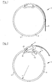
- Figur 1
- eine Wickelwelle mit einer Ausnehmung und einem darin angeordneten Einhänge-Profilstab mit der Warenbahn,
- Figur 2
- eine Wickelwelle und den Einhänge-Profilstab mit dem Ende der Warenbahn beim Einhängen in die Ausnehmung an der Wickelwelle,
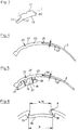
- Figur 3
- den Einhänge-Profilstab,
- Figur 4
- das Anschlusselement,
- Figur 5
- den Einhänge-Profilstab, verbunden mit einem Anschlusselement für den Stoff,
- Figur 6
- eine vergrössert dargestellte Ausnehmung im Mantel der Wickelwelle,
- Figur 7
- ein Einhänge-Profilstab mit integriertem Anschlusselement und am Einhänge-Profilstab befestigte Warenbahn,
- Figur 8
- eine perspektivische Darstellung von
Figur 7 und - Figur 9
- eine Wickelwelle mit der Ausnehmung und dem darin angeordneten Einhänge-Profilstab mit Anschlusselement und Warenbahn gemäss der zweiten Ausgestaltung der Erfindung.
- In
Figur 1 ist mit Bezugszeichen 1 ein System zur Verbindung einer Warenbahn 3, z.B. der Stoff für eine Markise, mit einer Wickelwelle 5 bezeichnet. Die manuell oder elektrisch antreibbare Wickelwelle 5 weist einen kreisrunden Querschnitt mit einer Manteloberfläche 7 auf. Die Wickelwelle 5 wird vorzugsweise als Aluminiumprofil hergestellt. Im Scheitel der Wickelwelle 5 inFigur 2 ist eine unter der Manteloberfläche 7 ausgebildete Ausnehmung 9 ersichtlich, über der ein axial verlaufender Schlitz 11 (Fig. 6 ) mit einer Breite b in der Manteloberfläche 7 ausgebildet ist. Die Breite b des Schlitzes 11 kann in Umfangsrichtung eine Ausdehnung bis zum Mass des Radius r der Wickelwelle 1 aufweisen. Selbstverständlich kann - in Abhängigkeit des Durchmessers der Wickelwelle 5 - auch eine wesentlich kleinere Öffnungsbreite b gewählt werden. Die Ausnehmung 9 hat im Querschnitt die Gestalt einer T-Nut oder, wie in den Figuren dargestellt, eines auf dem Rücken liegenden, flachgedrückten C's, dessen Rücken 13 leicht radial konvex nach aussen gebogen verlaufen kann, also in etwa parallel zum fehlenden Bereich in der Manteloberfläche 7 über dem Schlitz 11. Die Ausnehmung 9 weist eine innere Breite B auf. Die beiden Übergänge von der Manteloberfläche 7 in den Rücken 13 verlaufen in etwa in der Gestalt von gegeneinander gerichteten Halbkreisen (vergl.Fig. 1,2 ,6 ).
Die Ausnehmung 9 dient im System zur Aufnahme eines Einhänge-Profilstabs 17. Im Querschnitt weist der Einhänge-Profilstab 17 die Gestalt eines auf dem Kopf stehenden T's mit einer Bodenfläche 19 auf, deren konvexe Krümmung dem Rücken 13 in der Ausnehmung 9 an der Wickelwelle 5 entsprechen kann. Eine der Bodenfläche 19 gegenüberliegende Kontaktfläche 21 am Körper des Einhänge-Profilstabs 17 dient zur Aufnahme und Verbindung eines Anschlussbandes 23 oder direkt dem Kantenbereich der Warenbahn 3. Das Anschlussband 23 als Teil des Profilstabs 17 dient dazu, den vorderen Kantenbereich der Warenbahn 3 mit dem Einhänge-Profilstab 17 unlösbar zu verbinden. Das Anschlussband 23 weist inFigur 4 auf der rechten Seite an seiner radial aussenliegenden Oberfläche einen Absatz 25 auf, so dass die Oberfläche eine im dünneren Bereich 23' auf dem Anschlussband 23 befestigte Warenbahn 3 stufenlos oder absatzlos in die äussere Oberfläche 27 des Anschlussbandes 23 übergeht. Das Anschlussband 23 und eine darauf befestigte vordere Kante einer Warenbahn 3 liegen folglich in einer gemeinsamen konvex gebogenen Fläche. Das Anschlussband 23 kann an seinem linken freien Ende inFigur 4 eine grössere Wandstärke aufweisen als im anschliessenden, im Kontakt mit dem Einhänge-Profilstab 17 liegenden Abschnitt. Die Verbindung zwischen dem Einhänge-Profilstab 17 und dem Anschlussband 23 kann durch eine Verklebung oder, wie im Beispiel dargestellt, durch eine Ultraschallschweissung erfolgen, durch welche im Schweissbereich 29 eine unbedeutende Einbuchtung im Anschlussband 23 entstehen kann und allenfalls auch in der Kontaktfläche 21 des Einhänge-Profilstabs 17.
Der Einhänge-Profilstab 17 ist an dessen beiden Enden stufenförmig ausgebildet, so dass die obere Kontaktfläche 21 kürzer ist als die untere Bodenfläche 19.
Der erste stufenförmige Abschnitt 31 des Einhänge-Profilstabs 17 nimmt auf der linken Seite das dickere Ende des Anschlussbandes 23 auf und ist länger als der zweite stufenförmige Abschnitt 33 auf der rechten Seite in denFiguren 3 und 5 .
Die Dicke c1 des Einhänge-Profilstabs 17 im Anschluss an den ersten stufenförmigen Abschnitts 31 ist kleiner als die Dicke c2 vor dem zweiten stufenförmigen Abschnitt 33. Durch diese Massnahme gelangt die Oberfläche 27 des Anschlussbandes 23 stufenlos in die Manteloberfläche 7 der Wickelwelle 5.
Um eine optimale dauerhafte Verbindung zwischen dem Einhänge-Profilstab 17 und dem Anschlussband 23 an der Kontaktfläche 21 zu erlangen, sind diese aus einem ultraschallschweissbaren Material bestehend oder aus Materialien, die optimal und dauerhaft miteinander verklebbar sind. Das Anschlussband 23 ist vorzugsweise aus einem Kunststoff hergestellt, der biegsamer, weicher und zusammenpressbarer ist als das härtere und damit steife Material des Einhänge-Profilstabs 17. Der Einhänge-Profilstab 17 und das Anschlussband 23 können auch einteilig hergestellt sein, z.B. durch einen Extrudiervorgang oder einen Zweikomponenten-Spritzvorgang, so dass eine spätere Verklebung oder Verschweissung der beiden Elemente miteinander nicht mehr notwendig ist. - Nachfolgend wird die Funktionsweise der Verbindung zwischen der Wickelwelle 5 und dem Einhänge-Profilstab 17 mit dem daran befestigten Anschlussband 23 und der an diesem befestigten Warenbahn 3 der ersten Ausführungsform beschrieben. Nach dem Zuschneiden/Konfektionieren einer Warenbahn 3 für eine Markise wird deren vordere Kante bzw. der vordere Kantenbereich an dem Absatz 25 am Anschlussband 23 anstossend mit diesem verbunden. Die Verbindung kann durch eine Verklebung erfolgen oder durch eine Ultraschallschweissung, welche die beiden Materialien, nämlich die Warenbahn 3 und das Anschlussband 23, unlösbar miteinander verbindet. Die auf diese Weise vorbereitete Warenbahn 3 mit daran befestigtem Anschlussband 23 wird nun mit dem Einhänge-Profilstab 17 verbunden. Diese Verbindung kann ebenfalls durch eine Verklebung oder eine Ultraschallschweissung erfolgen. Selbstverständlich könnte auch zuerst der Einhänge-Profilstab 17 mit dem Anschlussband 23 verbunden werden und erst anschliessend die Warenbahn 3 an das Anschlussband 23 befestigt werden.
Die so vorbereitete Markise kann nun an der Wickelwelle 5, die im Sturz einer Fenster- oder Türöffnung oder in einem Wetterschutzgehäuse drehbar gelagert und durch einen hand- oder motorischen Antrieb drehbar ist, montiert werden. Dazu ist es nicht nötig die Wickelwelle 5 von deren Aufhängung und Antrieb zu lösen, sondern es wird der Einhänge-Profilstab 17 mit seinem vorne, d.h. auf der linken Seite in den Figuren, liegenden stufenförmigen Absatz 31 im Wesentlichen in spitzem Winkel zur Manteloberfläche in Richtung des Pfeils F in die Ausnehmung 9 eingeführt. Dabei untergreift der erste stufenförmige Abschnitt 31 den halbkreisförmigen Bereich 15 der Ausnehmung 9. Beim Einführen kann das verdickte Ende des Anschlussbandes 23, da es vorzugsweise aus einem weicheren Material als der zentrale Bereich des Profilstabs 17 besteht, etwas zurückgedrängt bzw. zurückgeschoben werden. Sobald der erste stufenförmige Abschnitt 31 unter die halbkreisförmige Kante der Ausnehmung 9 eingeschoben und untergeschoben ist, wird der Einhänge-Profilstab 17 in Richtung des Pfeiles P (Uhrzeigersinn) geschwenkt und gelangt danach mit seiner Bodenfläche 19 in Kontakt mit dem Rücken 13 der Ausnehmung 9 (vergl.Figur 1 ).
Sobald die Wickelwelle 5 im Gegenuhrzeigersinn in Drehung versetzt wird, wird einerseits die Warenbahn 3 radial an die Manteloberfläche 7 der Wickelwelle 5 angedrückt und der Einhänge-Profilstab 17 bzw. dessen zweiter stufenförmiger Abschnitt 33 in den kreisbogenförmigen Randbereich der Ausnehmung 9 hineingezogen. Der erste stufenförmige Abschnitt 31 verbleibt weiterhin radial gehalten im bogenförmigen Abschnitt der Ausnehmung 9 (linke Seite). Unterstützt wird das Einschieben im Uhrzeigersinn zusätzlich durch die Spannkraft des zusammengepressten weichen Endes des Anschlussbandes 23. Der Einhänge-Profilstab 17 liegt nun, die Ausnehmung 9 annähernd ausfüllend, an beiden Kanten gehalten in der Ausnehmung 9. Die Oberfläche 27 des Anschlussbandes 23 und die aussenliegende Oberfläche der Warenbahn 3 liegen in einer übergangslos verlaufenden im Wesentlichen kreisrunden Bahn in der Manteloberfläche 7 der Wickelwelle 5. - In einer weiteren Ausgestaltung der Erfindung gemäss den
Figuren 7 bis 9 ist der Einhänge-Profilstab 17' als Einheit mit dem Anschlussband 23" ausgebildet und damit einstückig aus zwei Komponenten unterschiedlicher Härte herstellbar und als Verbindungselement 35 bezeichnet. Das Verbindungselement 35 umfasst einen ersten stufenförmigen Abschnitt 31 und einen zweiten stufenförmigen Abschnitt 33. Im Weiteren ist auf dem ersten stufenförmigen Abschnitt 31 eine federnde Nase 37 angeformt sowie auf der gegenüberliegenden Seite über dem zweiten stufenförmigen Abschnitt 33 ein ebenfalls aus einem weicheren Material als der zentrale Teil des Verbindungselements 35 erzeugter Anschlussbandabschnitt 23'. Der Grundkörper des Verbindungselements 35 ist vorzugsweise aus einem Kunststoffmaterial mit grösserer Stärke und vor allem hoher Steifigkeit hergestellt als die Nase 37 und der Abschnitt 23' des Anschlussbands 23. Hergestellt wird das Verbindungselement im Spritzgiessverfahren mit zwei unterschiedlichen Kunststoffkomponenten. Die beiden Komponenten, nämlich die biegesteife für den Grundkörper und die elastisch verformbare für die Nase 37, und fakultativ auch für den Abschnitt 23', sind folglich untrennbar verbunden.
Die Verbindung der Warenbahn 3 mit dem eine geringere Stärke bzw. Dicke und vorzugsweise hoher Elastizität aufweisenden Abschnitt des Anschlussbands 23' ausserhalb des Absatzes 25, dient als Verbindungsbereich des Verbindungselements 35 mit der Warenbahn 3. Die Verbindung erfolgt entweder durch Kleben mit einem Kleber, durch gegenseitige Verklebung durch Wärmeeinwirkung oder durch eine Ultraschallschweissung. - Nachfolgend wird die Funktionsweise der Verbindung zwischen der Wickelwelle 5 und dem Einhänge-Profilstab 17 mit der daran befestigten Warenbahn 3 der zweiten Ausführungsform beschrieben.
Nach dem Zuschneiden/Konfektionieren der Warenbahn 3 wird deren vordere Kante am Absatz 25 des Anschlussbereichs 23' angelegt und durch einen Kleber, eine thermische Verschmelzung oder durch eine Ultraschallschweissung mit dem Anschlussbereich 23' verbunden. Das Verbinden der Warenbahn 3 mit dem Verbindungselement 35 kann vorzugsweise bereits in den Räumlichkeiten des Herstellers der Markise oder am Einsatzort kurz vor der Befestigung der Warenbahn 3 an der Wickelwelle 5 erfolgen.
Die am Verbindungselement 35 befestigte Warenbahn 3 wird dann, wie inFigur 2 des ersten Ausführungsbeispiels dargestellt, vor Ort, d.h. an der bereits an einem Gebäude befestigten Wickelwelle eingeklinkt. Dabei führt der Monteur den ersten stufenförmigen Abschnitt 31 am Einhänge-Profilstab (17) in spitzem Winkel zur Oberfläche des Mantels der Wickelwelle 5 unter die halbkreisförmige Ausnehmung 15 in der Ausnehmung 9 an der Wickelwelle 5 ein. Nun berührt die elastische Nase 37, die sich als Rippe über die gesamte Länge des Verbindungselements 15 oder über mindestens mehrere Teillängen erstreckt in Anlage mit dem Mantel 7 der Wickelwelle 5. Durch einen leichten Druck in Richtung der Kraft F inFigur 2 schiebt er den ersten stufenförmigen Abschnitt 31 vollständig in die halbkreisförmige Ausnehmung, bis der zweite stufenförmige Abschnitt 33 durch Verschwenken des Einhänge-Profilstabs 17 im Uhrzeigersinn in Anlage mit dem Rücken 13 der Ausnehmung 9 gelangt. Sobald die Kraft F auf den Einhänge-Profilstab 17 aufgehoben wird, verschiebt sich das Verbindungselement 35 im Uhrzeigersinn durch die Kraft der elastisch gespannten Nase 37 und gelangt mit seinem zweiten stufenförmigen Abschnitt 33 unter den halbkreisförmigen Bereich der Ausnehmung 9 auf der rechten Seite. Damit ist der Einhänge-Profilstab 17 in der Ausnehmung 9 verankert. Sobald die Wickelwelle 5 im Gegenuhrzeigersinn in Drehung versetzt wird, um die Warenbahn 3 aufwickeln zu können, wird das Verbindungselement 35 zusätzlich bis zum Anschlag in der Ausnehmung 9 verschoben, sofern nicht bereits die Kraft der Nase 37 das Verbindungselement 35 vollständig im Uhrzeigersinn verschoben hat. - Muss im Schadensfall eine Markise bzw. die Warenbahn 3 ausgetauscht werden, so lässt sich diese in umgekehrter Reihenfolge ohne Demontage der Wickelwelle 5 von dieser abnehmen.
Claims (11)
- System zum Verbinden einer Warenbahn (3) mit einer Wickelwelle (5) einer Sonnenschutzvorrichtung, umfassend ein Verbindungselement mit einem Einhänge-Profilstab (17) zur Befestigung an einer Vorderkante der Warenbahn (3) und eine axial verlaufende, in der Wickelwelle (5) ausgebildete Ausnehmung (9) mit einem in der Manteloberfläche (7) der Wickelwelle (5) verlaufenden Schlitz (11) zum Einführen des Verbindungselements in die darunterliegende Ausnehmung (9), wobei der Schlitz (11) eine geringere Breite b aufweist als die Breite B der Ausnehmung (9)
dadurch gekennzeichnet, dass
der Einhänge-Profilstab (17) einen im Wesentlichen steifen, nicht verformbaren Grundkörper mit entlang seiner beiden Längskanten ausgebildeten ersten und zweiten ebenfalls biegesteifen abgestuften Abschnitten (31,33) und über mindestens einem der Abschnitte (31,33) eine elastisch verformbare Nase (37) umfasst. - System nach Anspruch 1, dadurch gekennzeichnet, dass die elastisch verformbare Nase (37) als eine sich über die gesamte Länge des Verbindungselements (17) ununterbrochene Rippe ausgebildet ist oder aus einer Mehrzahl von Rippenabschnitten besteht, welche über dem ersten abgestuften Abschnitt (31) liegt.
- System nach einem der Ansprüche 1 oder 2, dadurch gekennzeichnet, dass die Nase (37) im Wesentlichen lotrecht auf dem ersten stufenförmigen Abschnitt (31) ausgebildet ist oder dass die Nase (37) sich horizontal verlaufend am zentralen Bereich des Verbindungselements (17) angeordnet über den ersten stufenförmigen Abschnitt (31) erstreckt.
- System nach einem der Ansprüche 1 bis 3, dadurch gekennzeichnet, dass der Einhänge-Profilstab (17) nach dem Einlegen in die Ausnehmung (9) durch eine tangential zur Oberfläche des Mantels der Wickelwelle (5) verlaufende Verschiebung in der Ausnehmung (9) verrastbar ist.
- System nach einem der Ansprüche 1 bis 4, dadurch gekennzeichnet,- dass die Ausnehmung (9) einen zur Manteloberfläche (7) beabstandet liegenden Rücken (13) umfasst, dessen Krümmung im Wesentlichen parallel zur Krümmung der Manteloberfläche (7) der Wickelwelle (5) verläuft oder geradlinig ausgebildet ist,- dass der Rücken (13) beidendig halbkreisförmig verlaufend in die beiden Längskanten des Schlitzes (11) in der Manteloberfläche (7) übergeht und- dass die Breite b des Schlitzes (11) kleiner ist als der Abstand B zwischen den beiden bogenförmig verlaufenden Seitenwänden der Ausnehmung (9).
- System nach einem der Ansprüche 1 bis 5, dadurch gekennzeichnet, dass der Einhänge-Profilstab (17) einen Querschnitt in Gestalt eines auf dem Kopf stehenden T's aufweist, wobei der horizontale Teil der Bodenfläche (19) des Einhänge-Profilstabs (17) an die Krümmung der Oberfläche des Rückens (13) der Basis der Ausnehmung (9) angepasst ist und die der Bodenfläche (19) gegenüberliegende Kontaktfläche (21) etwa dem Kreisabschnitt der über deren Schlitz (11) fehlenden Manteloberfläche (7) entspricht.
- System nach Anspruch 6, dadurch gekennzeichnet, dass die Kontaktfläche (21) kürzer ist als die Bodenfläche (19) und dass die Übergänge von der Kontaktfläche (21) in die Bodenfläche (19) als stufenförmige Abschnitte (31,33) ausgebildet sind.
- System nach Anspruch 7, dadurch gekennzeichnet, dass einer der beiden Abschnitte (31) und (33) einen längeren, die bogenförmig verlaufenden Seitenwände der Ausnehmung (9) untergreifenden Haltebereich aufweist als der Haltebereich am anderen Abschnitt (33).
- System nach einem der Ansprüche 1 bis 8, dadurch gekennzeichnet, dass ein Anschlussband (23) zur Verbindung der vorderen Kante der Warenbahn (3) mit dem Einhänge-Profilstab (17) ausgebildet ist, dessen Querschnitt entlang einer der beiden Kanten des Anschlussbandes (23) einen Absatz (25) aufweist, dessen Höhe h der Dicke der Warenbahn (3) entspricht.
- System nach Anspruch 9, dadurch gekennzeichnet, dass die Warenbahn (3) direkt am Einhänge-Profilstab (17) oder indirekt durch das Anschlussband (23) mit dem Einhänge-Profilstab (17) verbunden ist.
- System nach einem der Ansprüche 1 bis 10, dadurch gekennzeichnet, dass die Verbindung der Warenbahn (3) mit Einhänge-Profilstab (17) oder die Verbindungen der Warenbahn (3) mit dem Anschlussband (23) und das Anschlussband (23) mit dem Einhänge-Profilstab (17) durch eine Verklebung oder durch eine Ultraschallverschweissung erfolgt.
Applications Claiming Priority (2)
| Application Number | Priority Date | Filing Date | Title |
|---|---|---|---|
| CH00729/19A CH716257A1 (de) | 2019-06-06 | 2019-06-06 | System zum Verbinden einer Warenbahn mit einer Wickelwelle. |
| CH00545/20A CH716318A2 (de) | 2019-06-06 | 2020-05-07 | System zum Verbinden einer Warenbahn mit einer Wickelwelle einer Sonnenschutzvorrichtung. |
Publications (2)
| Publication Number | Publication Date |
|---|---|
| EP3748100A1 true EP3748100A1 (de) | 2020-12-09 |
| EP3748100B1 EP3748100B1 (de) | 2024-05-01 |
Family
ID=70736609
Family Applications (1)
| Application Number | Title | Priority Date | Filing Date |
|---|---|---|---|
| EP20174507.2A Active EP3748100B1 (de) | 2019-06-06 | 2020-05-13 | Verbindungslement zum verbinden einer warenbahn mit einer wickelwelle |
Country Status (1)
| Country | Link |
|---|---|
| EP (1) | EP3748100B1 (de) |
Cited By (4)
| Publication number | Priority date | Publication date | Assignee | Title |
|---|---|---|---|---|
| IT202100016799A1 (it) * | 2021-06-25 | 2022-12-25 | Plastex Sa | Profilo per il collegamento di una tenda ad un rullo avvolgitore, kit di trasporto di tale profilo e sistema di ancoraggio di una tenda ad una parete di supporto |
| IT202100016805A1 (it) * | 2021-06-25 | 2022-12-25 | Plastex Sa | Profilo per il collegamento di una tenda ad un rullo avvolgitore, kit di trasporto di tale profilo e sistema di ancoraggio di una tenda ad una parete di supporto |
| WO2022269578A1 (en) * | 2021-06-25 | 2022-12-29 | Plastex Sa | Profile for connecting a blind to a roller tube, transport kit of such profile and system for anchoring a blind to a support wall |
| EP4663894A1 (de) * | 2024-06-14 | 2025-12-17 | Griesser Holding AG | Wickelsystem und sonnenschutzeinrichtung mit einem solchen wickelsystem |
Citations (7)
| Publication number | Priority date | Publication date | Assignee | Title |
|---|---|---|---|---|
| JPS63117995U (de) * | 1987-01-26 | 1988-07-30 | ||
| US5384941A (en) * | 1990-06-28 | 1995-01-31 | Josef Welser Ohg Et Al. | Canvas-blind tube |
| JP3416767B2 (ja) * | 1998-07-24 | 2003-06-16 | モリト株式会社 | ロールブラインドのスクリーン取付構造 |
| US20060207731A1 (en) | 2004-10-05 | 2006-09-21 | Stephen Lukos | Roller tube having external slot for mounting sheet material |
| CH698032B1 (de) | 2005-05-10 | 2009-04-30 | Franz Kraler | Wickelwelle. |
| DE102018103796A1 (de) * | 2017-02-28 | 2018-08-30 | Warema Renkhoff Se | Befestigungselement für LED-Streifen in Nuten |
| EP3431678A1 (de) | 2017-07-19 | 2019-01-23 | Renson Sunprotection Screens NV | Abschirmvorrichtung |
-
2020
- 2020-05-13 EP EP20174507.2A patent/EP3748100B1/de active Active
Patent Citations (7)
| Publication number | Priority date | Publication date | Assignee | Title |
|---|---|---|---|---|
| JPS63117995U (de) * | 1987-01-26 | 1988-07-30 | ||
| US5384941A (en) * | 1990-06-28 | 1995-01-31 | Josef Welser Ohg Et Al. | Canvas-blind tube |
| JP3416767B2 (ja) * | 1998-07-24 | 2003-06-16 | モリト株式会社 | ロールブラインドのスクリーン取付構造 |
| US20060207731A1 (en) | 2004-10-05 | 2006-09-21 | Stephen Lukos | Roller tube having external slot for mounting sheet material |
| CH698032B1 (de) | 2005-05-10 | 2009-04-30 | Franz Kraler | Wickelwelle. |
| DE102018103796A1 (de) * | 2017-02-28 | 2018-08-30 | Warema Renkhoff Se | Befestigungselement für LED-Streifen in Nuten |
| EP3431678A1 (de) | 2017-07-19 | 2019-01-23 | Renson Sunprotection Screens NV | Abschirmvorrichtung |
Cited By (5)
| Publication number | Priority date | Publication date | Assignee | Title |
|---|---|---|---|---|
| IT202100016799A1 (it) * | 2021-06-25 | 2022-12-25 | Plastex Sa | Profilo per il collegamento di una tenda ad un rullo avvolgitore, kit di trasporto di tale profilo e sistema di ancoraggio di una tenda ad una parete di supporto |
| IT202100016805A1 (it) * | 2021-06-25 | 2022-12-25 | Plastex Sa | Profilo per il collegamento di una tenda ad un rullo avvolgitore, kit di trasporto di tale profilo e sistema di ancoraggio di una tenda ad una parete di supporto |
| WO2022269578A1 (en) * | 2021-06-25 | 2022-12-29 | Plastex Sa | Profile for connecting a blind to a roller tube, transport kit of such profile and system for anchoring a blind to a support wall |
| EP4290042A3 (de) * | 2021-06-25 | 2024-01-24 | Plastex SA | Profil zum verbinden eines rollos mit einem wickelwellenrohr, transportsatz eines solchen profils und system zur verankerung eines rollos an einer stützwand |
| EP4663894A1 (de) * | 2024-06-14 | 2025-12-17 | Griesser Holding AG | Wickelsystem und sonnenschutzeinrichtung mit einem solchen wickelsystem |
Also Published As
| Publication number | Publication date |
|---|---|
| EP3748100B1 (de) | 2024-05-01 |
Similar Documents
| Publication | Publication Date | Title |
|---|---|---|
| EP3748100B1 (de) | Verbindungslement zum verbinden einer warenbahn mit einer wickelwelle | |
| EP0627036B1 (de) | Befestigung einer dachabdichtungsbahn oder dergleichen | |
| DE102009023835B4 (de) | Befestigungs-Vorrichtung | |
| EP0530483A1 (de) | Aus nebeneinanderliegend angeordneten Blechbahnen bestehende Dacheindeckung | |
| EP2161384A2 (de) | Dichtungsband mit Stabilisierungselement | |
| EP2410225B1 (de) | Zementrohrmanschette zur korrosionshemmenden Abdeckung | |
| DE3842089A1 (de) | Vorrichtung zur befestigung von bahnfoermigem material, insbesondere von kunststoffolien oder dergleichen | |
| CH716318A2 (de) | System zum Verbinden einer Warenbahn mit einer Wickelwelle einer Sonnenschutzvorrichtung. | |
| DE202007014100U1 (de) | Gittergewebestreifen | |
| DE3924497A1 (de) | Fugenband mit verbesserten montageeigenschaften | |
| EP0162063B1 (de) | Befestiger | |
| DE102009057224A1 (de) | Markisentuch mit Wasserablauf | |
| DE102013214759B4 (de) | Fahrzeugkarosseriebauteil aus faserverstärktem Kunststoff | |
| DE2515822C2 (de) | ||
| DE29908620U1 (de) | Profil | |
| EP2487308A2 (de) | Befestigungselement für ein Abschlussblech, Befestigungsanordnung und Verfahren zur Befestigung eines Abschlussblechs | |
| DE6804257U (de) | Bauelementensatz zur befestigung von bespannungen an waenden und/oder decken | |
| DE102005029066A1 (de) | Montageelement | |
| DE102013203645B4 (de) | Markisenanordnung mit einer Halteeinrichtung für das Markisentuch | |
| DE2904907A1 (de) | Zaunpfahl und verfahren zu seiner herstellung | |
| DE69516530T2 (de) | Hülse | |
| DE10127280B4 (de) | Pfostenverbinder zur Verbindung von Pfosten und Sprossen im Blendrahmen in vertieften Fenstersystemen | |
| DE3240335C2 (de) | Verbindungsbeschlag | |
| DE20311075U1 (de) | Befestigungseinheit | |
| DE19858437A1 (de) | Verbindung zwischen gegenüberliegenden Profilleisten einer Türfüllung |
Legal Events
| Date | Code | Title | Description |
|---|---|---|---|
| PUAI | Public reference made under article 153(3) epc to a published international application that has entered the european phase |
Free format text: ORIGINAL CODE: 0009012 |
|
| STAA | Information on the status of an ep patent application or granted ep patent |
Free format text: STATUS: THE APPLICATION HAS BEEN PUBLISHED |
|
| AK | Designated contracting states |
Kind code of ref document: A1 Designated state(s): AL AT BE BG CH CY CZ DE DK EE ES FI FR GB GR HR HU IE IS IT LI LT LU LV MC MK MT NL NO PL PT RO RS SE SI SK SM TR |
|
| AX | Request for extension of the european patent |
Extension state: BA ME |
|
| STAA | Information on the status of an ep patent application or granted ep patent |
Free format text: STATUS: REQUEST FOR EXAMINATION WAS MADE |
|
| 17P | Request for examination filed |
Effective date: 20210511 |
|
| RBV | Designated contracting states (corrected) |
Designated state(s): AL AT BE BG CH CY CZ DE DK EE ES FI FR GB GR HR HU IE IS IT LI LT LU LV MC MK MT NL NO PL PT RO RS SE SI SK SM TR |
|
| STAA | Information on the status of an ep patent application or granted ep patent |
Free format text: STATUS: EXAMINATION IS IN PROGRESS |
|
| 17Q | First examination report despatched |
Effective date: 20220316 |
|
| GRAP | Despatch of communication of intention to grant a patent |
Free format text: ORIGINAL CODE: EPIDOSNIGR1 |
|
| STAA | Information on the status of an ep patent application or granted ep patent |
Free format text: STATUS: GRANT OF PATENT IS INTENDED |
|
| INTG | Intention to grant announced |
Effective date: 20240110 |
|
| GRAS | Grant fee paid |
Free format text: ORIGINAL CODE: EPIDOSNIGR3 |
|
| P01 | Opt-out of the competence of the unified patent court (upc) registered |
Effective date: 20240221 |
|
| GRAA | (expected) grant |
Free format text: ORIGINAL CODE: 0009210 |
|
| STAA | Information on the status of an ep patent application or granted ep patent |
Free format text: STATUS: THE PATENT HAS BEEN GRANTED |
|
| AK | Designated contracting states |
Kind code of ref document: B1 Designated state(s): AL AT BE BG CH CY CZ DE DK EE ES FI FR GB GR HR HU IE IS IT LI LT LU LV MC MK MT NL NO PL PT RO RS SE SI SK SM TR |
|
| REG | Reference to a national code |
Ref country code: GB Ref legal event code: FG4D Free format text: NOT ENGLISH |
|
| REG | Reference to a national code |
Ref country code: CH Ref legal event code: EP |
|
| REG | Reference to a national code |
Ref country code: DE Ref legal event code: R096 Ref document number: 502020007813 Country of ref document: DE |
|
| REG | Reference to a national code |
Ref country code: IE Ref legal event code: FG4D Free format text: LANGUAGE OF EP DOCUMENT: GERMAN |
|
| REG | Reference to a national code |
Ref country code: NL Ref legal event code: FP |
|
| REG | Reference to a national code |
Ref country code: LT Ref legal event code: MG9D |
|
| PG25 | Lapsed in a contracting state [announced via postgrant information from national office to epo] |
Ref country code: IS Free format text: LAPSE BECAUSE OF FAILURE TO SUBMIT A TRANSLATION OF THE DESCRIPTION OR TO PAY THE FEE WITHIN THE PRESCRIBED TIME-LIMIT Effective date: 20240901 |
|
| PG25 | Lapsed in a contracting state [announced via postgrant information from national office to epo] |
Ref country code: BG Free format text: LAPSE BECAUSE OF FAILURE TO SUBMIT A TRANSLATION OF THE DESCRIPTION OR TO PAY THE FEE WITHIN THE PRESCRIBED TIME-LIMIT Effective date: 20240501 |
|
| REG | Reference to a national code |
Ref country code: ES Ref legal event code: FG2A Ref document number: 2981604 Country of ref document: ES Kind code of ref document: T3 Effective date: 20241009 |
|
| PG25 | Lapsed in a contracting state [announced via postgrant information from national office to epo] |
Ref country code: HR Free format text: LAPSE BECAUSE OF FAILURE TO SUBMIT A TRANSLATION OF THE DESCRIPTION OR TO PAY THE FEE WITHIN THE PRESCRIBED TIME-LIMIT Effective date: 20240501 Ref country code: FI Free format text: LAPSE BECAUSE OF FAILURE TO SUBMIT A TRANSLATION OF THE DESCRIPTION OR TO PAY THE FEE WITHIN THE PRESCRIBED TIME-LIMIT Effective date: 20240501 |
|
| PG25 | Lapsed in a contracting state [announced via postgrant information from national office to epo] |
Ref country code: GR Free format text: LAPSE BECAUSE OF FAILURE TO SUBMIT A TRANSLATION OF THE DESCRIPTION OR TO PAY THE FEE WITHIN THE PRESCRIBED TIME-LIMIT Effective date: 20240802 |
|
| PG25 | Lapsed in a contracting state [announced via postgrant information from national office to epo] |
Ref country code: PT Free format text: LAPSE BECAUSE OF FAILURE TO SUBMIT A TRANSLATION OF THE DESCRIPTION OR TO PAY THE FEE WITHIN THE PRESCRIBED TIME-LIMIT Effective date: 20240902 |
|
| PG25 | Lapsed in a contracting state [announced via postgrant information from national office to epo] |
Ref country code: PL Free format text: LAPSE BECAUSE OF FAILURE TO SUBMIT A TRANSLATION OF THE DESCRIPTION OR TO PAY THE FEE WITHIN THE PRESCRIBED TIME-LIMIT Effective date: 20240501 |
|
| PG25 | Lapsed in a contracting state [announced via postgrant information from national office to epo] |
Ref country code: LV Free format text: LAPSE BECAUSE OF FAILURE TO SUBMIT A TRANSLATION OF THE DESCRIPTION OR TO PAY THE FEE WITHIN THE PRESCRIBED TIME-LIMIT Effective date: 20240501 |
|
| PG25 | Lapsed in a contracting state [announced via postgrant information from national office to epo] |
Ref country code: PT Free format text: LAPSE BECAUSE OF FAILURE TO SUBMIT A TRANSLATION OF THE DESCRIPTION OR TO PAY THE FEE WITHIN THE PRESCRIBED TIME-LIMIT Effective date: 20240902 Ref country code: PL Free format text: LAPSE BECAUSE OF FAILURE TO SUBMIT A TRANSLATION OF THE DESCRIPTION OR TO PAY THE FEE WITHIN THE PRESCRIBED TIME-LIMIT Effective date: 20240501 Ref country code: NO Free format text: LAPSE BECAUSE OF FAILURE TO SUBMIT A TRANSLATION OF THE DESCRIPTION OR TO PAY THE FEE WITHIN THE PRESCRIBED TIME-LIMIT Effective date: 20240801 Ref country code: LV Free format text: LAPSE BECAUSE OF FAILURE TO SUBMIT A TRANSLATION OF THE DESCRIPTION OR TO PAY THE FEE WITHIN THE PRESCRIBED TIME-LIMIT Effective date: 20240501 Ref country code: IS Free format text: LAPSE BECAUSE OF FAILURE TO SUBMIT A TRANSLATION OF THE DESCRIPTION OR TO PAY THE FEE WITHIN THE PRESCRIBED TIME-LIMIT Effective date: 20240901 Ref country code: HR Free format text: LAPSE BECAUSE OF FAILURE TO SUBMIT A TRANSLATION OF THE DESCRIPTION OR TO PAY THE FEE WITHIN THE PRESCRIBED TIME-LIMIT Effective date: 20240501 Ref country code: GR Free format text: LAPSE BECAUSE OF FAILURE TO SUBMIT A TRANSLATION OF THE DESCRIPTION OR TO PAY THE FEE WITHIN THE PRESCRIBED TIME-LIMIT Effective date: 20240802 Ref country code: FI Free format text: LAPSE BECAUSE OF FAILURE TO SUBMIT A TRANSLATION OF THE DESCRIPTION OR TO PAY THE FEE WITHIN THE PRESCRIBED TIME-LIMIT Effective date: 20240501 Ref country code: BG Free format text: LAPSE BECAUSE OF FAILURE TO SUBMIT A TRANSLATION OF THE DESCRIPTION OR TO PAY THE FEE WITHIN THE PRESCRIBED TIME-LIMIT Effective date: 20240501 Ref country code: RS Free format text: LAPSE BECAUSE OF FAILURE TO SUBMIT A TRANSLATION OF THE DESCRIPTION OR TO PAY THE FEE WITHIN THE PRESCRIBED TIME-LIMIT Effective date: 20240801 |
|
| PG25 | Lapsed in a contracting state [announced via postgrant information from national office to epo] |
Ref country code: DK Free format text: LAPSE BECAUSE OF FAILURE TO SUBMIT A TRANSLATION OF THE DESCRIPTION OR TO PAY THE FEE WITHIN THE PRESCRIBED TIME-LIMIT Effective date: 20240501 |
|
| PG25 | Lapsed in a contracting state [announced via postgrant information from national office to epo] |
Ref country code: EE Free format text: LAPSE BECAUSE OF FAILURE TO SUBMIT A TRANSLATION OF THE DESCRIPTION OR TO PAY THE FEE WITHIN THE PRESCRIBED TIME-LIMIT Effective date: 20240501 |
|
| PG25 | Lapsed in a contracting state [announced via postgrant information from national office to epo] |
Ref country code: CZ Free format text: LAPSE BECAUSE OF FAILURE TO SUBMIT A TRANSLATION OF THE DESCRIPTION OR TO PAY THE FEE WITHIN THE PRESCRIBED TIME-LIMIT Effective date: 20240501 |
|
| PG25 | Lapsed in a contracting state [announced via postgrant information from national office to epo] |
Ref country code: SK Free format text: LAPSE BECAUSE OF FAILURE TO SUBMIT A TRANSLATION OF THE DESCRIPTION OR TO PAY THE FEE WITHIN THE PRESCRIBED TIME-LIMIT Effective date: 20240501 Ref country code: RO Free format text: LAPSE BECAUSE OF FAILURE TO SUBMIT A TRANSLATION OF THE DESCRIPTION OR TO PAY THE FEE WITHIN THE PRESCRIBED TIME-LIMIT Effective date: 20240501 |
|
| PG25 | Lapsed in a contracting state [announced via postgrant information from national office to epo] |
Ref country code: SM Free format text: LAPSE BECAUSE OF FAILURE TO SUBMIT A TRANSLATION OF THE DESCRIPTION OR TO PAY THE FEE WITHIN THE PRESCRIBED TIME-LIMIT Effective date: 20240501 |
|
| PG25 | Lapsed in a contracting state [announced via postgrant information from national office to epo] |
Ref country code: SM Free format text: LAPSE BECAUSE OF FAILURE TO SUBMIT A TRANSLATION OF THE DESCRIPTION OR TO PAY THE FEE WITHIN THE PRESCRIBED TIME-LIMIT Effective date: 20240501 Ref country code: SK Free format text: LAPSE BECAUSE OF FAILURE TO SUBMIT A TRANSLATION OF THE DESCRIPTION OR TO PAY THE FEE WITHIN THE PRESCRIBED TIME-LIMIT Effective date: 20240501 Ref country code: RO Free format text: LAPSE BECAUSE OF FAILURE TO SUBMIT A TRANSLATION OF THE DESCRIPTION OR TO PAY THE FEE WITHIN THE PRESCRIBED TIME-LIMIT Effective date: 20240501 Ref country code: EE Free format text: LAPSE BECAUSE OF FAILURE TO SUBMIT A TRANSLATION OF THE DESCRIPTION OR TO PAY THE FEE WITHIN THE PRESCRIBED TIME-LIMIT Effective date: 20240501 Ref country code: DK Free format text: LAPSE BECAUSE OF FAILURE TO SUBMIT A TRANSLATION OF THE DESCRIPTION OR TO PAY THE FEE WITHIN THE PRESCRIBED TIME-LIMIT Effective date: 20240501 Ref country code: CZ Free format text: LAPSE BECAUSE OF FAILURE TO SUBMIT A TRANSLATION OF THE DESCRIPTION OR TO PAY THE FEE WITHIN THE PRESCRIBED TIME-LIMIT Effective date: 20240501 Ref country code: MC Free format text: LAPSE BECAUSE OF FAILURE TO SUBMIT A TRANSLATION OF THE DESCRIPTION OR TO PAY THE FEE WITHIN THE PRESCRIBED TIME-LIMIT Effective date: 20240501 |
|
| REG | Reference to a national code |
Ref country code: DE Ref legal event code: R097 Ref document number: 502020007813 Country of ref document: DE |
|
| PLBE | No opposition filed within time limit |
Free format text: ORIGINAL CODE: 0009261 |
|
| STAA | Information on the status of an ep patent application or granted ep patent |
Free format text: STATUS: NO OPPOSITION FILED WITHIN TIME LIMIT |
|
| 26N | No opposition filed |
Effective date: 20250204 |
|
| PG25 | Lapsed in a contracting state [announced via postgrant information from national office to epo] |
Ref country code: IE Free format text: LAPSE BECAUSE OF NON-PAYMENT OF DUE FEES Effective date: 20240513 |
|
| PG25 | Lapsed in a contracting state [announced via postgrant information from national office to epo] |
Ref country code: SI Free format text: LAPSE BECAUSE OF FAILURE TO SUBMIT A TRANSLATION OF THE DESCRIPTION OR TO PAY THE FEE WITHIN THE PRESCRIBED TIME-LIMIT Effective date: 20240501 |
|
| PGFP | Annual fee paid to national office [announced via postgrant information from national office to epo] |
Ref country code: NL Payment date: 20250522 Year of fee payment: 6 |
|
| PGFP | Annual fee paid to national office [announced via postgrant information from national office to epo] |
Ref country code: DE Payment date: 20250519 Year of fee payment: 6 |
|
| PGFP | Annual fee paid to national office [announced via postgrant information from national office to epo] |
Ref country code: GB Payment date: 20250522 Year of fee payment: 6 Ref country code: ES Payment date: 20250616 Year of fee payment: 6 |
|
| PGFP | Annual fee paid to national office [announced via postgrant information from national office to epo] |
Ref country code: LU Payment date: 20250520 Year of fee payment: 6 Ref country code: BE Payment date: 20250520 Year of fee payment: 6 Ref country code: IT Payment date: 20250530 Year of fee payment: 6 |
|
| PGFP | Annual fee paid to national office [announced via postgrant information from national office to epo] |
Ref country code: FR Payment date: 20250523 Year of fee payment: 6 |
|
| PGFP | Annual fee paid to national office [announced via postgrant information from national office to epo] |
Ref country code: CH Payment date: 20250601 Year of fee payment: 6 |
|
| PGFP | Annual fee paid to national office [announced via postgrant information from national office to epo] |
Ref country code: AT Payment date: 20250519 Year of fee payment: 6 |
|
| PG25 | Lapsed in a contracting state [announced via postgrant information from national office to epo] |
Ref country code: CY Free format text: LAPSE BECAUSE OF FAILURE TO SUBMIT A TRANSLATION OF THE DESCRIPTION OR TO PAY THE FEE WITHIN THE PRESCRIBED TIME-LIMIT; INVALID AB INITIO Effective date: 20200513 |
|
| PG25 | Lapsed in a contracting state [announced via postgrant information from national office to epo] |
Ref country code: HU Free format text: LAPSE BECAUSE OF FAILURE TO SUBMIT A TRANSLATION OF THE DESCRIPTION OR TO PAY THE FEE WITHIN THE PRESCRIBED TIME-LIMIT; INVALID AB INITIO Effective date: 20200513 |
|
| PG25 | Lapsed in a contracting state [announced via postgrant information from national office to epo] |
Ref country code: SE Free format text: LAPSE BECAUSE OF FAILURE TO SUBMIT A TRANSLATION OF THE DESCRIPTION OR TO PAY THE FEE WITHIN THE PRESCRIBED TIME-LIMIT Effective date: 20240501 |