EP3748100A1 - Système de liaison d'une bande de matière à un arbre d'enroulement - Google Patents
Système de liaison d'une bande de matière à un arbre d'enroulement Download PDFInfo
- Publication number
- EP3748100A1 EP3748100A1 EP20174507.2A EP20174507A EP3748100A1 EP 3748100 A1 EP3748100 A1 EP 3748100A1 EP 20174507 A EP20174507 A EP 20174507A EP 3748100 A1 EP3748100 A1 EP 3748100A1
- Authority
- EP
- European Patent Office
- Prior art keywords
- recess
- winding shaft
- web
- section
- rod
- Prior art date
- Legal status (The legal status is an assumption and is not a legal conclusion. Google has not performed a legal analysis and makes no representation as to the accuracy of the status listed.)
- Granted
Links
Images


Classifications
-
- E—FIXED CONSTRUCTIONS
- E04—BUILDING
- E04F—FINISHING WORK ON BUILDINGS, e.g. STAIRS, FLOORS
- E04F10/00—Sunshades, e.g. Florentine blinds or jalousies; Outside screens; Awnings or baldachins
- E04F10/02—Sunshades, e.g. Florentine blinds or jalousies; Outside screens; Awnings or baldachins of flexible canopy materials, e.g. canvas ; Baldachins
- E04F10/06—Sunshades, e.g. Florentine blinds or jalousies; Outside screens; Awnings or baldachins of flexible canopy materials, e.g. canvas ; Baldachins comprising a roller-blind with means for holding the end away from a building
- E04F10/0633—Arrangements for fastening the flexible canopy material to the supporting structure
-
- E—FIXED CONSTRUCTIONS
- E06—DOORS, WINDOWS, SHUTTERS, OR ROLLER BLINDS IN GENERAL; LADDERS
- E06B—FIXED OR MOVABLE CLOSURES FOR OPENINGS IN BUILDINGS, VEHICLES, FENCES OR LIKE ENCLOSURES IN GENERAL, e.g. DOORS, WINDOWS, BLINDS, GATES
- E06B9/00—Screening or protective devices for wall or similar openings, with or without operating or securing mechanisms; Closures of similar construction
- E06B9/24—Screens or other constructions affording protection against light, especially against sunshine; Similar screens for privacy or appearance; Slat blinds
- E06B9/40—Roller blinds
- E06B9/42—Parts or details of roller blinds, e.g. suspension devices, blind boxes
- E06B9/44—Rollers therefor; Fastening roller blinds to rollers
- E06B9/46—Rollers therefor; Fastening roller blinds to rollers by clamping bars
Definitions
- the subject of the invention is a system for connecting a web of material to a winding shaft according to the preamble of patent claim 1.
- Awnings as sun and / or rain protection comprise a web of material that can be wound up on a winding shaft in order to be able to protect it and stow it in a small space when not in use.
- a rod is inserted into a hemstitch in the edge of the fabric to be connected to the winding shaft, thereby forming a welt bead.
- a welt flap can also be attached to the edge of the fabric, for example sewn on.
- an axially extending recess is attached to the latter under the jacket surface as a welt rail, into which the welt can be inserted.
- the recess is approximately circular in cross section and the recess is only connected to the surface of the winding shaft at a narrow point, so that after the material web is inserted with the piping, the material web is held in the axial direction.
- Such connections between the fabric web and the winding shaft are safe and relatively easy to handle.
- a disadvantage of such a connection is the effort involved in inserting the welt, since it can only be introduced into the winding shaft at the end and consequently the winding shaft must be exposed at its end for insertion.
- Another disadvantage is that the web of fabric, for example an awning fabric made of acrylic, which can at least have a thickness of 1 to 3 mm, is led out radially out of the recess on the winding shaft and thus the area after the first loop and further loopings when winding the awning, which lies over the slot of the recess, is slightly lifted off and consequently this area is defined by this bead on the awning when it is extended.
- an arrangement for connecting a web of material, in particular awning, to a winding shaft is also known.
- a recess is made in the winding shaft, the base of which is formed in the shape of a segment of a circular arc and which extends in cross section in an S-shape on the two side edges Areas are formed so that the slot in the jacket surface of the winding shaft has a smaller width than the base of the recess.
- the recess forms space for a bar that can be clicked into place through a groove that is essentially T-shaped in cross section, so that it does not protrude beyond the jacket surface of the winding shaft, but can reach under the protruding edge areas of the slot with its lateral edges.
- a groove is made on the underside of the bar so that the area of the bar outside the groove, which must be made of a relatively soft, flexible plastic material , when the rod is placed and simultaneously compressed, it can reject the recess or the slot over its entire length and so the width of the rod is shortened for a short time.
- the rod area swings away from the groove again outside the groove and thus holds the rod firmly within the recess.
- a bore running along its longitudinal edges is embedded in the rod and is connected to the surface of the rod by a slot.
- the rod cannot be securely held in it after it has been clipped into the recess in the winding shaft, because if an increased tensile force acts on the awning, especially if the recess on the winding shaft is not in the upper apex of the same, but comes to lie further down, the rod is bent and thereby the elastic holding area can be pulled out of the recess, since it is known that it must be designed to be pivotable on the rod for insertion.
- the connection between awning and rod is therefore very complex and, on the other hand, the anchoring of the rod after assembly on the winding shaft is not guaranteed in every position.
- a winding shaft is known in which an S-shaped holding area is attached along the edge of the awning, which must be connected to the winding shaft. This engages in a circular hole in the winding shaft that is connected to the surface through a slot.
- a secure hold of the awning is only guaranteed if the awning has already been wrapped around the winding shaft and over the S-shaped one The hook comes to rest and presses it radially onto the winding shaft. A secure hold is therefore not guaranteed.
- connection system makes it possible to arrange the connection area of the material web completely under the jacket surface of the winding shaft, so that there is no step-like transition on the surface of the winding shaft and after the first wrapping of the winding shaft by the material web, the area of the second winding layer coming to lie above the connection area the web is not pushed radially outwards, but comes to lie within the arcuate course of the jacket surface of the winding shaft.
- the transition from the first looping to the second is consequently stepless without the formation of a bead.
- This is achieved by a hanging profile rod which is connected on one side to the edge area of the web and which can be completely inserted into a recess under the surface of the winding shaft and fastened there so that it can be locked in place.
- the system has a very advantageous and time-saving effect, as the suspension profile bar with the fabric web is radially attached to the one installed in a door or window lintel Winding shaft brought up and can be hung and locked in a recess in the outer surface without tools. There is no axial displacement during use, as the suspension profile rod engages in the recess. It is therefore no longer necessary to dismantle the winding shaft in order to introduce the connecting element.
- the suspension profile bar can be connected directly to the edge area of the material web in a simple and cost-effective manner, in that the connection is made by ultrasonic welding or by gluing. In addition, there is no need to attach a seam to the edge of the web, but the cut edge can be attached to the hanging profile bar without any further treatment.
- a transition element can be attached in advance to the edge of the material web, which in turn is connected to the hanging profile bar.
- the transition element improves the smooth run-in of the material web from the recess into the outer surface of the winding shaft.
- the recess can be produced very easily on the winding shaft.
- the recess has a slot which is very wide in relation to its depth and which enables the insertion of the suspension profile rod in the radial direction and does not, as before, require dismantling of the winding shaft in order to be inserted axially.
- the hitherto necessarily to be formed on the web of material with a rod arranged therein to form a Keder bead as a fastening element on the winding shaft is omitted.
- the hanging profile bar can be attached directly to the cut, uncleaned web edge with little effort by gluing or ultrasonic welding.
- the uncleaned leading edge of the material web is connected to a connecting tape by welding or gluing.
- the connecting tape for its part, is also connected to the hanging profile bar by gluing or welding. This enables the suspension profile bar to be inserted completely into the slot-shaped recess and no parts protrude beyond the jacket surface of the winding shaft. If a connecting tape is also inserted between the material web and the hanging profile bar, a completely seamless connection between the winding shaft and the material web can be achieved.
- the suspension profile rod and the connecting tape which is preferably made of a softer material than the profile rod, can also be made in one piece, so that only one connection to the fabric edge has to be made. If an awning's web has to be replaced after years due to a defect, the web with the attached profile bar can be pushed out of the recess and replaced with a new or repaired web without dismantling the winding shaft.
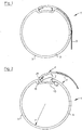
- a system for connecting a web 3, for example the fabric for an awning, to a winding shaft 5 is designated by reference numeral 1.
- the winding shaft 5, which can be driven manually or electrically, has a circular cross section with a jacket surface 7.
- the winding shaft 5 is preferably made as an aluminum profile.
- a recess 9 formed under the jacket surface 7 can be seen, above which an axially extending slot 11 ( Fig. 6 ) is formed with a width b in the jacket surface 7.
- the width b of the slot 11 can extend in the circumferential direction up to the dimension of the radius r of the winding shaft 1.
- a significantly smaller opening width b can also be selected depending on the diameter of the winding shaft 5, a significantly smaller opening width b can also be selected.
- the cross-section of the recess 9 has the shape of a T-groove or, as shown in the figures, a flattened C lying on its back, the back 13 of which can be bent slightly radially convex outwards, i.e. approximately parallel to the missing area in the Jacket surface 7 above the slot 11.
- the recess 9 has an inner width B.
- the two transitions from the jacket surface 7 to the back 13 run roughly in the shape of semicircles directed towards one another (cf. Fig. 1,2 , 6th ).
- the recess 9 is used in the system to receive a suspension profile rod 17.
- the Suspension profile rod 17 has the shape of an upside-down T with a bottom surface 19, the convex curvature of which can correspond to the back 13 in the recess 9 on the winding shaft 5.
- a contact surface 21 opposite the bottom surface 19 on the body of the suspension profile bar 17 serves to receive and connect a connecting tape 23 or directly to the edge area of the web 3.
- the connecting tape 23 as part of the profiled bar 17 is used to attach the front edge area of the web 3 to the hook -Profile rod 17 to be permanently connected.
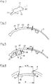
- the connecting tape 23 has in Figure 4 on the right-hand side on its radially outer surface, a shoulder 25, so that the surface of a web 3 fastened in the thinner area 23 ′ on the connecting tape 23 merges steplessly or steplessly into the outer surface 27 of the connecting tape 23.
- the connecting band 23 and a front edge of a web 3 fastened thereon consequently lie in a common convexly curved surface.
- the connecting tape 23 can at its left free end in Figure 4 have a greater wall thickness than in the subsequent section lying in contact with the suspension profile rod 17.
- connection between the suspension profile rod 17 and the connecting tape 23 can be made by gluing or, as shown in the example, by ultrasonic welding, through which an insignificant indentation in the weld area 29 is formed
- Connection tape 23 can arise and possibly also in the contact surface 21 of the hanging profile rod 17.
- the suspension profile bar 17 is designed in a step shape at both ends, so that the upper contact surface 21 is shorter than the lower base surface 19.
- the first step-shaped section 31 of the suspension profile rod 17 takes on the thicker end of the connecting tape 23 on the left side and is longer than the second step-shaped section 33 on the right side in the Figures 3 and 5 .
- the thickness c 1 of the suspension profile rod 17 following the first step-shaped section 31 is smaller than the thickness c 2 before the second step-shaped section 33.
- the surface 27 of the connecting strip 23 reaches the jacket surface 7 of the winding shaft 5 in a stepless manner.
- these are made of an ultrasonically weldable material or of materials that can be optimally and permanently glued to one another.
- the connecting band 23 is preferably made of a plastic that is more flexible, softer and more compressible than the harder and thus stiff material of the hanging profile rod 17.
- the hanging profile rod 17 and the connecting band 23 can also be made in one piece, for example by a Extrusion process or a two-component injection process, so that later gluing or welding of the two elements is no longer necessary.
- connection The mode of operation of the connection between the winding shaft 5 and the suspension profile bar 17 with the connecting tape 23 attached to it and the web of material 3 of the first embodiment attached to it is described below.
- a material web 3 for an awning has been cut / assembled, its front edge or the front edge region is connected to the shoulder 25 on the connecting tape 23 in abutment therewith.
- the connection can be made by gluing or by ultrasonic welding, which permanently connects the two materials, namely the web 3 and the connecting tape 23, to one another.
- the fabric web 3 prepared in this way with the connecting tape 23 attached to it is now connected to the hanging profile bar 17.
- This connection can also be made by gluing or ultrasonic welding.
- the suspension profile bar 17 could also be connected to the connecting tape 23 first and only then the web 3 could be attached to the connecting tape 23.
- the awning prepared in this way can now be mounted on the winding shaft 5, which is rotatably mounted in the lintel of a window or door opening or in a weatherproof housing, and is or motorized drive can be rotated. To do this, it is not necessary to detach the winding shaft 5 from its suspension and drive, but instead the suspension profile bar 17 with its stepped shoulder 31 located at the front, ie on the left side in the figures, is essentially at an acute angle to the jacket surface in the direction of the arrow F is inserted into the recess 9.
- the first step-shaped section 31 engages under the semicircular area 15 of the recess 9.
- the thickened end of the connecting tape 23 since it is preferably made of a softer material than the central area of the profile rod 17, can be pushed back or pushed back a little.
- the suspension profile rod 17 is pivoted in the direction of the arrow P (clockwise) and then comes with its bottom surface 19 in contact with the back 13 of the recess 9 ( compare Figure 1 ).
- the web 3 is pressed radially against the outer surface 7 of the winding shaft 5 and the suspension profile rod 17 or its second step-shaped section 33 is drawn into the circular arc-shaped edge area of the recess 9.
- the first step-shaped section 31 continues to remain radially held in the arcuate section of the recess 9 (left side).
- the clockwise insertion is also supported by the tension of the compressed soft end of the connecting tape 23.
- the hanging profile bar 17 is now, almost filling the recess 9, held in the recess 9 on both edges.
- the surface 27 of the connecting tape 23 and the outer one The surfaces of the web 3 lie in a seamlessly running, essentially circular path in the jacket surface 7 of the winding shaft 5.
- the suspension profile rod 17 ' is designed as a unit with the connecting band 23 "and can thus be produced in one piece from two components of different hardness and is referred to as a connecting element 35.
- the connecting element 35 comprises a first step-shaped section 31 and a second step-shaped section 33
- a resilient nose 37 is molded onto the first step-shaped section 31 and, on the opposite side above the second step-shaped section 33, a connecting band section 23 ', which is also made of a softer material than the central part of the connecting element 35 greater strength and above all produced higher rigidity than the nose 37 and the section 23 'of the connecting strip 23.
- the connecting element is produced by injection molding with two different plastic components.
- connection of the web 3 with the lower strength or thickness and preferably high elasticity having section of the connecting tape 23 'outside the shoulder 25, serves as a connection area of the connecting element 35 with the web 3.
- the connection is made either by gluing with an adhesive Mutual bonding by the action of heat or by ultrasonic welding.
- connection between the winding shaft 5 and the suspension profile bar 17 with the material web 3 of the second embodiment attached thereto is described below.
- the material web 3 has been cut / assembled, its front edge is placed on the shoulder 25 of the connection area 23 'and connected to the connection area 23' by an adhesive, a thermal fusion or by an ultrasonic welding.
- the connection of the web 3 with the connecting element 35 can preferably already in the premises of the manufacturer of the awning or at the place of use shortly before the attachment of the web 3 to the winding shaft 5.
- the web 3 fastened to the connecting element 35 is then, as in FIG Figure 2 of the first embodiment shown, on site, ie latched onto the winding shaft already attached to a building.
- the fitter introduces the first step-shaped section 31 on the suspension profile bar (17) at an acute angle to the surface of the jacket of the winding shaft 5 under the semicircular recess 15 in the recess 9 on the winding shaft 5.
- the elastic nose 37 which extends as a rib over the entire length of the connecting element 15 or over at least several partial lengths, now touches the jacket 7 of the winding shaft 5.
- the connecting element 35 moves clockwise by the force of the elastically tensioned nose 37 and its second step-shaped section 33 comes under the semicircular area of the recess 9 on the right-hand side. So that the suspension profile bar 17 is in the Recess 9 anchored. As soon as the winding shaft 5 is rotated counterclockwise in order to be able to wind up the web 3, the connecting element 35 is also moved up to the stop in the recess 9, unless the force of the nose 37 has already moved the connecting element 35 completely clockwise.
- an awning or the material web 3 has to be replaced in the event of damage, it can be removed from the winding shaft 5 in the reverse order without dismantling it.
Landscapes
- Engineering & Computer Science (AREA)
- Architecture (AREA)
- Structural Engineering (AREA)
- Civil Engineering (AREA)
- Building Awnings And Sunshades (AREA)
Applications Claiming Priority (2)
| Application Number | Priority Date | Filing Date | Title |
|---|---|---|---|
| CH00729/19A CH716257A1 (de) | 2019-06-06 | 2019-06-06 | System zum Verbinden einer Warenbahn mit einer Wickelwelle. |
| CH00545/20A CH716318A2 (de) | 2019-06-06 | 2020-05-07 | System zum Verbinden einer Warenbahn mit einer Wickelwelle einer Sonnenschutzvorrichtung. |
Publications (2)
| Publication Number | Publication Date |
|---|---|
| EP3748100A1 true EP3748100A1 (fr) | 2020-12-09 |
| EP3748100B1 EP3748100B1 (fr) | 2024-05-01 |
Family
ID=70736609
Family Applications (1)
| Application Number | Title | Priority Date | Filing Date |
|---|---|---|---|
| EP20174507.2A Active EP3748100B1 (fr) | 2019-06-06 | 2020-05-13 | Élément de liaison pour lier une bande de matière à un arbre d'enroulement |
Country Status (1)
| Country | Link |
|---|---|
| EP (1) | EP3748100B1 (fr) |
Cited By (4)
| Publication number | Priority date | Publication date | Assignee | Title |
|---|---|---|---|---|
| IT202100016805A1 (it) * | 2021-06-25 | 2022-12-25 | Plastex Sa | Profilo per il collegamento di una tenda ad un rullo avvolgitore, kit di trasporto di tale profilo e sistema di ancoraggio di una tenda ad una parete di supporto |
| IT202100016799A1 (it) * | 2021-06-25 | 2022-12-25 | Plastex Sa | Profilo per il collegamento di una tenda ad un rullo avvolgitore, kit di trasporto di tale profilo e sistema di ancoraggio di una tenda ad una parete di supporto |
| WO2022269578A1 (fr) * | 2021-06-25 | 2022-12-29 | Plastex Sa | Profilé de liaison d'un store à un tube de rouleau, kit de transport d'un tel profilé et système d'ancrage d'un store à un mur porteur |
| EP4663894A1 (fr) * | 2024-06-14 | 2025-12-17 | Griesser Holding AG | Système d'enroulement et dispositif de protection solaire doté d'un tel système d'enroulement |
Citations (7)
| Publication number | Priority date | Publication date | Assignee | Title |
|---|---|---|---|---|
| JPS63117995U (fr) * | 1987-01-26 | 1988-07-30 | ||
| US5384941A (en) * | 1990-06-28 | 1995-01-31 | Josef Welser Ohg Et Al. | Canvas-blind tube |
| JP3416767B2 (ja) * | 1998-07-24 | 2003-06-16 | モリト株式会社 | ロールブラインドのスクリーン取付構造 |
| US20060207731A1 (en) | 2004-10-05 | 2006-09-21 | Stephen Lukos | Roller tube having external slot for mounting sheet material |
| CH698032B1 (de) | 2005-05-10 | 2009-04-30 | Franz Kraler | Wickelwelle. |
| DE102018103796A1 (de) * | 2017-02-28 | 2018-08-30 | Warema Renkhoff Se | Befestigungselement für LED-Streifen in Nuten |
| EP3431678A1 (fr) | 2017-07-19 | 2019-01-23 | Renson Sunprotection Screens NV | Dispositif d'ecran |
-
2020
- 2020-05-13 EP EP20174507.2A patent/EP3748100B1/fr active Active
Patent Citations (7)
| Publication number | Priority date | Publication date | Assignee | Title |
|---|---|---|---|---|
| JPS63117995U (fr) * | 1987-01-26 | 1988-07-30 | ||
| US5384941A (en) * | 1990-06-28 | 1995-01-31 | Josef Welser Ohg Et Al. | Canvas-blind tube |
| JP3416767B2 (ja) * | 1998-07-24 | 2003-06-16 | モリト株式会社 | ロールブラインドのスクリーン取付構造 |
| US20060207731A1 (en) | 2004-10-05 | 2006-09-21 | Stephen Lukos | Roller tube having external slot for mounting sheet material |
| CH698032B1 (de) | 2005-05-10 | 2009-04-30 | Franz Kraler | Wickelwelle. |
| DE102018103796A1 (de) * | 2017-02-28 | 2018-08-30 | Warema Renkhoff Se | Befestigungselement für LED-Streifen in Nuten |
| EP3431678A1 (fr) | 2017-07-19 | 2019-01-23 | Renson Sunprotection Screens NV | Dispositif d'ecran |
Cited By (5)
| Publication number | Priority date | Publication date | Assignee | Title |
|---|---|---|---|---|
| IT202100016805A1 (it) * | 2021-06-25 | 2022-12-25 | Plastex Sa | Profilo per il collegamento di una tenda ad un rullo avvolgitore, kit di trasporto di tale profilo e sistema di ancoraggio di una tenda ad una parete di supporto |
| IT202100016799A1 (it) * | 2021-06-25 | 2022-12-25 | Plastex Sa | Profilo per il collegamento di una tenda ad un rullo avvolgitore, kit di trasporto di tale profilo e sistema di ancoraggio di una tenda ad una parete di supporto |
| WO2022269578A1 (fr) * | 2021-06-25 | 2022-12-29 | Plastex Sa | Profilé de liaison d'un store à un tube de rouleau, kit de transport d'un tel profilé et système d'ancrage d'un store à un mur porteur |
| EP4290042A3 (fr) * | 2021-06-25 | 2024-01-24 | Plastex SA | Profilé de liaison d'un store à un tube de rouleau, kit de transport d'un tel profilé et système d'ancrage d'un store à un mur porteur |
| EP4663894A1 (fr) * | 2024-06-14 | 2025-12-17 | Griesser Holding AG | Système d'enroulement et dispositif de protection solaire doté d'un tel système d'enroulement |
Also Published As
| Publication number | Publication date |
|---|---|
| EP3748100B1 (fr) | 2024-05-01 |
Similar Documents
| Publication | Publication Date | Title |
|---|---|---|
| EP3748100B1 (fr) | Élément de liaison pour lier une bande de matière à un arbre d'enroulement | |
| EP0627036B1 (fr) | Fixation d'une bande d'etanchement de toit ou similaire | |
| DE102009023835B4 (de) | Befestigungs-Vorrichtung | |
| EP0530483A1 (fr) | Couverture de toit constituée de tôles juxtaposées | |
| EP2161384A2 (fr) | Bande d'étanchéité dotée d'un élément de stabilisation | |
| EP2410225B1 (fr) | Manchette de tuyau en ciment pour le recouvrement anti-corrosion | |
| DE3842089A1 (de) | Vorrichtung zur befestigung von bahnfoermigem material, insbesondere von kunststoffolien oder dergleichen | |
| CH716318A2 (de) | System zum Verbinden einer Warenbahn mit einer Wickelwelle einer Sonnenschutzvorrichtung. | |
| DE202007014100U1 (de) | Gittergewebestreifen | |
| DE3924497A1 (de) | Fugenband mit verbesserten montageeigenschaften | |
| DE202007010766U1 (de) | Befestigungsvorrichtung | |
| EP0162063B1 (fr) | Dispositif de fixation | |
| DE102009057224A1 (de) | Markisentuch mit Wasserablauf | |
| DE102013214759B4 (de) | Fahrzeugkarosseriebauteil aus faserverstärktem Kunststoff | |
| DE2515822C2 (fr) | ||
| DE29908620U1 (de) | Profil | |
| DE102011000606A1 (de) | Befestigungselement für ein Abschlussblech, Befestigungsanordnung und Verfahren zur Befestigung eines Abschlussblechs | |
| DE6804257U (de) | Bauelementensatz zur befestigung von bespannungen an waenden und/oder decken | |
| DE102005029066A1 (de) | Montageelement | |
| DE102013203645B4 (de) | Markisenanordnung mit einer Halteeinrichtung für das Markisentuch | |
| DE2904907A1 (de) | Zaunpfahl und verfahren zu seiner herstellung | |
| DE10127280B4 (de) | Pfostenverbinder zur Verbindung von Pfosten und Sprossen im Blendrahmen in vertieften Fenstersystemen | |
| DE2549503A1 (de) | Einrichtung zum befestigen von zeltplanen an geruest-bauteilen von grosszelten | |
| DE3240335C2 (de) | Verbindungsbeschlag | |
| DE20311075U1 (de) | Befestigungseinheit |
Legal Events
| Date | Code | Title | Description |
|---|---|---|---|
| PUAI | Public reference made under article 153(3) epc to a published international application that has entered the european phase |
Free format text: ORIGINAL CODE: 0009012 |
|
| STAA | Information on the status of an ep patent application or granted ep patent |
Free format text: STATUS: THE APPLICATION HAS BEEN PUBLISHED |
|
| AK | Designated contracting states |
Kind code of ref document: A1 Designated state(s): AL AT BE BG CH CY CZ DE DK EE ES FI FR GB GR HR HU IE IS IT LI LT LU LV MC MK MT NL NO PL PT RO RS SE SI SK SM TR |
|
| AX | Request for extension of the european patent |
Extension state: BA ME |
|
| STAA | Information on the status of an ep patent application or granted ep patent |
Free format text: STATUS: REQUEST FOR EXAMINATION WAS MADE |
|
| 17P | Request for examination filed |
Effective date: 20210511 |
|
| RBV | Designated contracting states (corrected) |
Designated state(s): AL AT BE BG CH CY CZ DE DK EE ES FI FR GB GR HR HU IE IS IT LI LT LU LV MC MK MT NL NO PL PT RO RS SE SI SK SM TR |
|
| STAA | Information on the status of an ep patent application or granted ep patent |
Free format text: STATUS: EXAMINATION IS IN PROGRESS |
|
| 17Q | First examination report despatched |
Effective date: 20220316 |
|
| GRAP | Despatch of communication of intention to grant a patent |
Free format text: ORIGINAL CODE: EPIDOSNIGR1 |
|
| STAA | Information on the status of an ep patent application or granted ep patent |
Free format text: STATUS: GRANT OF PATENT IS INTENDED |
|
| INTG | Intention to grant announced |
Effective date: 20240110 |
|
| GRAS | Grant fee paid |
Free format text: ORIGINAL CODE: EPIDOSNIGR3 |
|
| P01 | Opt-out of the competence of the unified patent court (upc) registered |
Effective date: 20240221 |
|
| GRAA | (expected) grant |
Free format text: ORIGINAL CODE: 0009210 |
|
| STAA | Information on the status of an ep patent application or granted ep patent |
Free format text: STATUS: THE PATENT HAS BEEN GRANTED |
|
| AK | Designated contracting states |
Kind code of ref document: B1 Designated state(s): AL AT BE BG CH CY CZ DE DK EE ES FI FR GB GR HR HU IE IS IT LI LT LU LV MC MK MT NL NO PL PT RO RS SE SI SK SM TR |
|
| REG | Reference to a national code |
Ref country code: GB Ref legal event code: FG4D Free format text: NOT ENGLISH |
|
| REG | Reference to a national code |
Ref country code: CH Ref legal event code: EP |
|
| REG | Reference to a national code |
Ref country code: DE Ref legal event code: R096 Ref document number: 502020007813 Country of ref document: DE |
|
| REG | Reference to a national code |
Ref country code: IE Ref legal event code: FG4D Free format text: LANGUAGE OF EP DOCUMENT: GERMAN |
|
| REG | Reference to a national code |
Ref country code: NL Ref legal event code: FP |
|
| REG | Reference to a national code |
Ref country code: LT Ref legal event code: MG9D |
|
| PG25 | Lapsed in a contracting state [announced via postgrant information from national office to epo] |
Ref country code: IS Free format text: LAPSE BECAUSE OF FAILURE TO SUBMIT A TRANSLATION OF THE DESCRIPTION OR TO PAY THE FEE WITHIN THE PRESCRIBED TIME-LIMIT Effective date: 20240901 |
|
| PG25 | Lapsed in a contracting state [announced via postgrant information from national office to epo] |
Ref country code: BG Free format text: LAPSE BECAUSE OF FAILURE TO SUBMIT A TRANSLATION OF THE DESCRIPTION OR TO PAY THE FEE WITHIN THE PRESCRIBED TIME-LIMIT Effective date: 20240501 |
|
| REG | Reference to a national code |
Ref country code: ES Ref legal event code: FG2A Ref document number: 2981604 Country of ref document: ES Kind code of ref document: T3 Effective date: 20241009 |
|
| PG25 | Lapsed in a contracting state [announced via postgrant information from national office to epo] |
Ref country code: HR Free format text: LAPSE BECAUSE OF FAILURE TO SUBMIT A TRANSLATION OF THE DESCRIPTION OR TO PAY THE FEE WITHIN THE PRESCRIBED TIME-LIMIT Effective date: 20240501 Ref country code: FI Free format text: LAPSE BECAUSE OF FAILURE TO SUBMIT A TRANSLATION OF THE DESCRIPTION OR TO PAY THE FEE WITHIN THE PRESCRIBED TIME-LIMIT Effective date: 20240501 |
|
| PG25 | Lapsed in a contracting state [announced via postgrant information from national office to epo] |
Ref country code: GR Free format text: LAPSE BECAUSE OF FAILURE TO SUBMIT A TRANSLATION OF THE DESCRIPTION OR TO PAY THE FEE WITHIN THE PRESCRIBED TIME-LIMIT Effective date: 20240802 |
|
| PG25 | Lapsed in a contracting state [announced via postgrant information from national office to epo] |
Ref country code: PT Free format text: LAPSE BECAUSE OF FAILURE TO SUBMIT A TRANSLATION OF THE DESCRIPTION OR TO PAY THE FEE WITHIN THE PRESCRIBED TIME-LIMIT Effective date: 20240902 |
|
| PG25 | Lapsed in a contracting state [announced via postgrant information from national office to epo] |
Ref country code: PL Free format text: LAPSE BECAUSE OF FAILURE TO SUBMIT A TRANSLATION OF THE DESCRIPTION OR TO PAY THE FEE WITHIN THE PRESCRIBED TIME-LIMIT Effective date: 20240501 |
|
| PG25 | Lapsed in a contracting state [announced via postgrant information from national office to epo] |
Ref country code: LV Free format text: LAPSE BECAUSE OF FAILURE TO SUBMIT A TRANSLATION OF THE DESCRIPTION OR TO PAY THE FEE WITHIN THE PRESCRIBED TIME-LIMIT Effective date: 20240501 |
|
| PG25 | Lapsed in a contracting state [announced via postgrant information from national office to epo] |
Ref country code: PT Free format text: LAPSE BECAUSE OF FAILURE TO SUBMIT A TRANSLATION OF THE DESCRIPTION OR TO PAY THE FEE WITHIN THE PRESCRIBED TIME-LIMIT Effective date: 20240902 Ref country code: PL Free format text: LAPSE BECAUSE OF FAILURE TO SUBMIT A TRANSLATION OF THE DESCRIPTION OR TO PAY THE FEE WITHIN THE PRESCRIBED TIME-LIMIT Effective date: 20240501 Ref country code: NO Free format text: LAPSE BECAUSE OF FAILURE TO SUBMIT A TRANSLATION OF THE DESCRIPTION OR TO PAY THE FEE WITHIN THE PRESCRIBED TIME-LIMIT Effective date: 20240801 Ref country code: LV Free format text: LAPSE BECAUSE OF FAILURE TO SUBMIT A TRANSLATION OF THE DESCRIPTION OR TO PAY THE FEE WITHIN THE PRESCRIBED TIME-LIMIT Effective date: 20240501 Ref country code: IS Free format text: LAPSE BECAUSE OF FAILURE TO SUBMIT A TRANSLATION OF THE DESCRIPTION OR TO PAY THE FEE WITHIN THE PRESCRIBED TIME-LIMIT Effective date: 20240901 Ref country code: HR Free format text: LAPSE BECAUSE OF FAILURE TO SUBMIT A TRANSLATION OF THE DESCRIPTION OR TO PAY THE FEE WITHIN THE PRESCRIBED TIME-LIMIT Effective date: 20240501 Ref country code: GR Free format text: LAPSE BECAUSE OF FAILURE TO SUBMIT A TRANSLATION OF THE DESCRIPTION OR TO PAY THE FEE WITHIN THE PRESCRIBED TIME-LIMIT Effective date: 20240802 Ref country code: FI Free format text: LAPSE BECAUSE OF FAILURE TO SUBMIT A TRANSLATION OF THE DESCRIPTION OR TO PAY THE FEE WITHIN THE PRESCRIBED TIME-LIMIT Effective date: 20240501 Ref country code: BG Free format text: LAPSE BECAUSE OF FAILURE TO SUBMIT A TRANSLATION OF THE DESCRIPTION OR TO PAY THE FEE WITHIN THE PRESCRIBED TIME-LIMIT Effective date: 20240501 Ref country code: RS Free format text: LAPSE BECAUSE OF FAILURE TO SUBMIT A TRANSLATION OF THE DESCRIPTION OR TO PAY THE FEE WITHIN THE PRESCRIBED TIME-LIMIT Effective date: 20240801 |
|
| PG25 | Lapsed in a contracting state [announced via postgrant information from national office to epo] |
Ref country code: DK Free format text: LAPSE BECAUSE OF FAILURE TO SUBMIT A TRANSLATION OF THE DESCRIPTION OR TO PAY THE FEE WITHIN THE PRESCRIBED TIME-LIMIT Effective date: 20240501 |
|
| PG25 | Lapsed in a contracting state [announced via postgrant information from national office to epo] |
Ref country code: EE Free format text: LAPSE BECAUSE OF FAILURE TO SUBMIT A TRANSLATION OF THE DESCRIPTION OR TO PAY THE FEE WITHIN THE PRESCRIBED TIME-LIMIT Effective date: 20240501 |
|
| PG25 | Lapsed in a contracting state [announced via postgrant information from national office to epo] |
Ref country code: CZ Free format text: LAPSE BECAUSE OF FAILURE TO SUBMIT A TRANSLATION OF THE DESCRIPTION OR TO PAY THE FEE WITHIN THE PRESCRIBED TIME-LIMIT Effective date: 20240501 |
|
| PG25 | Lapsed in a contracting state [announced via postgrant information from national office to epo] |
Ref country code: SK Free format text: LAPSE BECAUSE OF FAILURE TO SUBMIT A TRANSLATION OF THE DESCRIPTION OR TO PAY THE FEE WITHIN THE PRESCRIBED TIME-LIMIT Effective date: 20240501 Ref country code: RO Free format text: LAPSE BECAUSE OF FAILURE TO SUBMIT A TRANSLATION OF THE DESCRIPTION OR TO PAY THE FEE WITHIN THE PRESCRIBED TIME-LIMIT Effective date: 20240501 |
|
| PG25 | Lapsed in a contracting state [announced via postgrant information from national office to epo] |
Ref country code: SM Free format text: LAPSE BECAUSE OF FAILURE TO SUBMIT A TRANSLATION OF THE DESCRIPTION OR TO PAY THE FEE WITHIN THE PRESCRIBED TIME-LIMIT Effective date: 20240501 |
|
| PG25 | Lapsed in a contracting state [announced via postgrant information from national office to epo] |
Ref country code: SM Free format text: LAPSE BECAUSE OF FAILURE TO SUBMIT A TRANSLATION OF THE DESCRIPTION OR TO PAY THE FEE WITHIN THE PRESCRIBED TIME-LIMIT Effective date: 20240501 Ref country code: SK Free format text: LAPSE BECAUSE OF FAILURE TO SUBMIT A TRANSLATION OF THE DESCRIPTION OR TO PAY THE FEE WITHIN THE PRESCRIBED TIME-LIMIT Effective date: 20240501 Ref country code: RO Free format text: LAPSE BECAUSE OF FAILURE TO SUBMIT A TRANSLATION OF THE DESCRIPTION OR TO PAY THE FEE WITHIN THE PRESCRIBED TIME-LIMIT Effective date: 20240501 Ref country code: EE Free format text: LAPSE BECAUSE OF FAILURE TO SUBMIT A TRANSLATION OF THE DESCRIPTION OR TO PAY THE FEE WITHIN THE PRESCRIBED TIME-LIMIT Effective date: 20240501 Ref country code: DK Free format text: LAPSE BECAUSE OF FAILURE TO SUBMIT A TRANSLATION OF THE DESCRIPTION OR TO PAY THE FEE WITHIN THE PRESCRIBED TIME-LIMIT Effective date: 20240501 Ref country code: CZ Free format text: LAPSE BECAUSE OF FAILURE TO SUBMIT A TRANSLATION OF THE DESCRIPTION OR TO PAY THE FEE WITHIN THE PRESCRIBED TIME-LIMIT Effective date: 20240501 Ref country code: MC Free format text: LAPSE BECAUSE OF FAILURE TO SUBMIT A TRANSLATION OF THE DESCRIPTION OR TO PAY THE FEE WITHIN THE PRESCRIBED TIME-LIMIT Effective date: 20240501 |
|
| REG | Reference to a national code |
Ref country code: DE Ref legal event code: R097 Ref document number: 502020007813 Country of ref document: DE |
|
| PLBE | No opposition filed within time limit |
Free format text: ORIGINAL CODE: 0009261 |
|
| STAA | Information on the status of an ep patent application or granted ep patent |
Free format text: STATUS: NO OPPOSITION FILED WITHIN TIME LIMIT |
|
| 26N | No opposition filed |
Effective date: 20250204 |
|
| PG25 | Lapsed in a contracting state [announced via postgrant information from national office to epo] |
Ref country code: IE Free format text: LAPSE BECAUSE OF NON-PAYMENT OF DUE FEES Effective date: 20240513 |
|
| PG25 | Lapsed in a contracting state [announced via postgrant information from national office to epo] |
Ref country code: SI Free format text: LAPSE BECAUSE OF FAILURE TO SUBMIT A TRANSLATION OF THE DESCRIPTION OR TO PAY THE FEE WITHIN THE PRESCRIBED TIME-LIMIT Effective date: 20240501 |
|
| PGFP | Annual fee paid to national office [announced via postgrant information from national office to epo] |
Ref country code: NL Payment date: 20250522 Year of fee payment: 6 |
|
| PGFP | Annual fee paid to national office [announced via postgrant information from national office to epo] |
Ref country code: DE Payment date: 20250519 Year of fee payment: 6 |
|
| PGFP | Annual fee paid to national office [announced via postgrant information from national office to epo] |
Ref country code: GB Payment date: 20250522 Year of fee payment: 6 Ref country code: ES Payment date: 20250616 Year of fee payment: 6 |
|
| PGFP | Annual fee paid to national office [announced via postgrant information from national office to epo] |
Ref country code: LU Payment date: 20250520 Year of fee payment: 6 Ref country code: BE Payment date: 20250520 Year of fee payment: 6 Ref country code: IT Payment date: 20250530 Year of fee payment: 6 |
|
| PGFP | Annual fee paid to national office [announced via postgrant information from national office to epo] |
Ref country code: FR Payment date: 20250523 Year of fee payment: 6 |
|
| PGFP | Annual fee paid to national office [announced via postgrant information from national office to epo] |
Ref country code: CH Payment date: 20250601 Year of fee payment: 6 |
|
| PGFP | Annual fee paid to national office [announced via postgrant information from national office to epo] |
Ref country code: AT Payment date: 20250519 Year of fee payment: 6 |
|
| PG25 | Lapsed in a contracting state [announced via postgrant information from national office to epo] |
Ref country code: CY Free format text: LAPSE BECAUSE OF FAILURE TO SUBMIT A TRANSLATION OF THE DESCRIPTION OR TO PAY THE FEE WITHIN THE PRESCRIBED TIME-LIMIT; INVALID AB INITIO Effective date: 20200513 |
|
| PG25 | Lapsed in a contracting state [announced via postgrant information from national office to epo] |
Ref country code: HU Free format text: LAPSE BECAUSE OF FAILURE TO SUBMIT A TRANSLATION OF THE DESCRIPTION OR TO PAY THE FEE WITHIN THE PRESCRIBED TIME-LIMIT; INVALID AB INITIO Effective date: 20200513 |
|
| PG25 | Lapsed in a contracting state [announced via postgrant information from national office to epo] |
Ref country code: SE Free format text: LAPSE BECAUSE OF FAILURE TO SUBMIT A TRANSLATION OF THE DESCRIPTION OR TO PAY THE FEE WITHIN THE PRESCRIBED TIME-LIMIT Effective date: 20240501 |