EP3748112B1 - Anti-fall device for a lift gate, in particular for protecting machinery - Google Patents
Anti-fall device for a lift gate, in particular for protecting machinery Download PDFInfo
- Publication number
- EP3748112B1 EP3748112B1 EP20175158.3A EP20175158A EP3748112B1 EP 3748112 B1 EP3748112 B1 EP 3748112B1 EP 20175158 A EP20175158 A EP 20175158A EP 3748112 B1 EP3748112 B1 EP 3748112B1
- Authority
- EP
- European Patent Office
- Prior art keywords
- gate
- carrier
- stop element
- stop
- latch
- Prior art date
- Legal status (The legal status is an assumption and is not a legal conclusion. Google has not performed a legal analysis and makes no representation as to the accuracy of the status listed.)
- Active
Links
Images




Classifications
-
- E—FIXED CONSTRUCTIONS
- E05—LOCKS; KEYS; WINDOW OR DOOR FITTINGS; SAFES
- E05D—HINGES OR SUSPENSION DEVICES FOR DOORS, WINDOWS OR WINGS
- E05D13/00—Accessories for sliding or lifting wings, e.g. pulleys, safety catches
- E05D13/003—Anti-dropping devices
- E05D13/006—Anti-dropping devices fixed to the wing, i.e. safety catches
-
- E—FIXED CONSTRUCTIONS
- E06—DOORS, WINDOWS, SHUTTERS, OR ROLLER BLINDS IN GENERAL; LADDERS
- E06B—FIXED OR MOVABLE CLOSURES FOR OPENINGS IN BUILDINGS, VEHICLES, FENCES OR LIKE ENCLOSURES IN GENERAL, e.g. DOORS, WINDOWS, BLINDS, GATES
- E06B9/00—Screening or protective devices for wall or similar openings, with or without operating or securing mechanisms; Closures of similar construction
- E06B9/56—Operating, guiding or securing devices or arrangements for roll-type closures; Spring drums; Tape drums; Counterweighting arrangements therefor
- E06B9/80—Safety measures against dropping or unauthorised opening; Braking or immobilising devices; Devices for limiting unrolling
- E06B9/82—Safety measures against dropping or unauthorised opening; Braking or immobilising devices; Devices for limiting unrolling automatic
- E06B9/84—Safety measures against dropping or unauthorised opening; Braking or immobilising devices; Devices for limiting unrolling automatic against dropping
-
- E—FIXED CONSTRUCTIONS
- E05—LOCKS; KEYS; WINDOW OR DOOR FITTINGS; SAFES
- E05Y—INDEXING SCHEME ASSOCIATED WITH SUBCLASSES E05D AND E05F, RELATING TO CONSTRUCTION ELEMENTS, ELECTRIC CONTROL, POWER SUPPLY, POWER SIGNAL OR TRANSMISSION, USER INTERFACES, MOUNTING OR COUPLING, DETAILS, ACCESSORIES, AUXILIARY OPERATIONS NOT OTHERWISE PROVIDED FOR, APPLICATION THEREOF
- E05Y2999/00—Subject-matter not otherwise provided for in this subclass
Definitions
- the present invention relates to fall protection for a lifting gate, in particular a machine protection lifting gate, and a lifting gate, in particular a machine protection lifting gate, with such a fall protection.
- Elevating gates of which the present invention is particularly concerned, are used in industry as part of a safety fencing around a work area, such as a robotic work station, to provide access to the otherwise fenced work area.
- a lifting gate can also be part of an intermediate subdivision of such a work area and must be moved up and down frequently and quickly, particularly in this application.
- a fall protection for the overhead door is provided for this purpose, which mechanically locks the overhead door against downward movement by providing a pneumatically or hydraulically actuated bolt that can be brought into a bolt-eyelet connection.
- the latch is actively actuated to bring it into its locked position within the eyelet.
- the bolt is actuated in order to remove it from the eyelet and thus release the mechanical locking. Due to the active control, conventional fall protection systems are complex and require a lot of maintenance.
- EP 0 721 043 A1 discloses a monitoring device for a support cable of a door leaf with an electric catch device connected to the support cable and a mechanical catch device which are connected in series in such a way that first the electric catch device and then the mechanical catch device responds.
- JPH0740994 U discloses a locking device for preventing vertical movement of the roller shutter in an upward direction, which comprises an end slat movable in a vertical direction for joint movement with the roller shutter and a support element which is stationary in the vertical direction and which can be brought into a mechanically locked engagement blocking vertical movement of the end slat ; wherein the locking device also has at least one pawl which is connected at least indirectly to the end lamella in an articulated manner and which can be pivoted into mechanically locking engagement with the support element, and a stop element is mounted in a resilient manner on the end lamella, the end lamella having a pin in which the pawl is guided in that it is pivoted in the direction of the support element when the stop element deflects, with the stop element being assigned a stop in a predetermined vertical end position, against which the stop element strikes during a vertical movement of the end plate.
- the present invention is based on the object of specifying a fall protection for a lifting gate, wherein the fall protection does not require an active control, can be produced inexpensively, is advantageously low-maintenance or maintenance-free and works reliably.
- a fall protection according to the invention for a lifting gate in particular a machine protection lifting gate of the type explained at the outset, has at least one mechanical locking device which comprises a gate carrier that can be moved in a vertical direction for joint movement with the lifting gate and a support element that is stationary in the vertical direction, with the gate carrier and the support element in a mechanically locked engagement blocking a vertical movement, in particular a downward movement, of the gate carrier.
- the locking device comprises at least one pawl which is connected at least indirectly to the door carrier in an articulated manner and which can be pivoted into the mechanically locked engagement with the support element.
- a stop element is mounted in a resilient manner on the gate carrier, which has a guide in which the pawl is guided in such a way that, when the Stop element is pivoted in the direction of the support element.
- the stop element In a predetermined vertical end position, in particular in a predetermined upper position, the stop element is assigned a stop against which the stop element strikes during a vertical movement, in particular an upward movement, of the gate carrier.
- the fall protection is provided at the upper end of the lifting gate in order to prevent an undesired movement of the gate carrier and thus of the lifting gate in a vertical downward movement.
- it can also be used at a lower end of the lifting gate to prevent a vertical movement of the gate carrier or the lifting gate in an upward direction when a robot arm strikes from below.
- the anti-fall device prevents the gate carrier or lifting gate from moving downwards.
- the support element includes a bolt and the pawl includes a mouth, wherein the mouth can be hung on the bolt by pivoting the pawl.
- the support element comprises a corresponding mouth or a recess and the pawl has a bolt which can be hung in the mouth or the recess.
- Other embodiments are possible.
- the guide includes a link with which a link block connected to the pawl is in engagement.
- the pawl is rotatably connected at least indirectly to the door support about a horizontal axis of rotation.
- a pivoting movement can also be considered, in which the pawl executes a combined rotating and sliding movement.
- the stop is mounted so that it can be displaced in the vertical direction against a spring force. In this way, tolerances when approaching the end position of the gate carrier or the lifting gate can be compensated for if, for example, a drive device does not move the lifting gate exactly into the desired end position.
- the stop element In order to safely intercept an impact of a robot arm from above on the gate carrier without the risk of the gate carrier being released from its mechanical locking with the support element, the stop element preferably completely covers the gate carrier on its upper side. In the case of protection against the gate carrier being displaced upwards, the stop element would preferably completely cover the underside of the gate carrier.
- the stop element can be mounted on the gate carrier, for example, by means of at least one compression spring or with a multiplicity of compression springs.
- a lifting gate according to the invention has at least one gate field and at least one drive device for moving the gate field up and down in a vertical direction.
- the goal field is connected to the goal support of a fall protection device according to the invention.
- the goal carrier is formed by the goal field itself.
- the goal field can have several segments that can be moved one behind the other. Each segment that is comparatively lower is advantageously positioned on the side of the goal field above it that faces away from the work area or danger area in which, for example, a robot is standing, in order to prevent, for example, a robot arm from above falling onto a segment that is not covered by the stop element beats. As a rule, it can be sufficient to secure only the top goal area with a fall protection device according to the invention.
- the drive device is advantageously connected vertically below the stop element and separately from the stop element on the door panel and/or on the door carrier.
- the drive device can, for example, comprise a chain drive or a belt drive, which is connected to the door field and/or to the door carrier.
- a chain drive or a belt drive which is connected to the door field and/or to the door carrier.
- other drive devices can also be considered.
- the fall protection according to the invention advantageously does not require an external control and advantageously works purely mechanically.
- Various springs that work together are advantageously matched to one another in terms of spring force. If, for example, the stop is slidably mounted against the force of at least one spring, this spring or spring combination has in particular a greater spring force than the spring or spring combination with which the stop element is supported on the door carrier.
- the spring force of the spring/spring combination assigned to the stop is twice the spring force that is made available by the at least one spring or spring combination with which the stop element is mounted on the door carrier.
- the stop itself can be designed, for example, in the form of a rubber buffer.
- the stop element strikes the stop first and is moved relative to the gate support as the gate support continues to be moved.
- the pawl connected to the gate carrier is pivoted due to the guide provided on the stop element, so that it moves in the direction of the support element for its mechanical locking and is finally locked with the support element.
- a body for example a robot arm
- strikes the stop element from above a force is thereby exerted on the stop element, which pushes it in the direction of the gate carrier.
- a further or increasing locking force is exerted on the pawl, which pushes it in the direction of the support element. A movement of the pawl out of the mechanical locking with the support element is reliably avoided.
- a drive force of the drive device acts on the lifting door or the door support, in the sense of a vertical movement, in particular downward movement, of the lifting door or door support
- the door support is removed from the stop element, which initially presses against the stop with the spring force of the spring/spring combination between the door support and the stop element is depressed and remains there, and the guide pivots the latch back out of its locking engagement with the support member.
- the mechanical locking between the pawl and the support element is canceled and the gate carrier or the lifting gate can be moved, in particular downwards, as desired.
- a spring-loaded stop allows the gate support or the lifting gate to move by a predetermined further distance in the direction of the stop, even if the stop element has already hit the stop and has moved relatively in the direction of the gate carrier so that the pawl locks with the support element can be, because then the stop yields elastically due to its resilient suspension.
- this does not disturb the secure locking between the pawl and the support element and damage to the drive device, for example a chain drive or belt drive, is prevented.
- the risk of the stop element or the stop being damaged is also minimized.
- a fall protection according to the invention with a mechanical locking device 1 is shown, which comprises a gate carrier 2 that can be moved in a vertical direction Z and a support element 3 that is stationary in the vertical direction Z.
- the gate carrier 2 can be brought into a mechanically locked engagement with the support element 3 .
- the locking device 1 also includes a pawl 4 which is connected to the gate carrier 2 and which can be pivoted into the mechanically locked engagement with the support element 3 .
- the pawl 4 comprises a bolt 4.2 which can be hooked into a mouth 3.2 or a recess in the support element 3.
- a stop element 5 is resiliently mounted on the gate support 2 and has a guide 6 in which the pawl 4 is guided in such a way that it is pivoted in the direction of the support element 3 when the stop element 5 is compressed in the direction of the gate support 2 .
- the guide 6 comprises a connecting link 6.1, with which a sliding block 8 connected to the pawl 4 engages in order to force the pivoting movement of the pawl 4 when the stop element 5 is moved towards the door carrier 2.
- the gate carrier 2 is mounted slidably in two lateral gate guides 13, which is located in the Extend in the vertical direction Z.
- a stop 7 is provided at the upper end of the lateral door guides 13, against which the stop element 5 strikes when the lifting door 10 or the door carrier 2 moves into its upper end position.
- the stop element 5 first hits the stop 7 and is thereby stopped in its movement in the vertical direction Z, whereas the door carrier 2, which is driven, is moved further up in the vertical direction Z.
- the stop element 5 springs against the force of the at least one compression spring 9, with which it is mounted on the gate carrier 2, in the direction of the gate carrier 2.
- link 6.1 forces link block 8 outwards in a direction transverse to vertical direction Z.
- the pawl 4 is pivoted outwards in the direction of the support element 3 and is brought with its bolt 4.2 into an area above the mouth 3.2 in the support element 3 or is inserted directly into the mouth 3.2.
- the drive device not shown here is switched off and the lifting gate 10 or the gate carrier 2 is in its upper end position.
- the lifting gate 10 or the gate carrier 2 is held in the upper end position by the drive device because the drive device has a corresponding self-locking mechanism.
- this self-locking is not large enough to support a comparatively large downward force that is exerted on the lifting gate 10 .
- Such a comparatively large force can be exerted, for example, by a robot arm hitting the gate carrier 2 or the stop element 5 from above, and without the fall protection, the lifting gate 10 would be knocked down.
- a drive device acts on the gate carrier 2 and exerts a downward force on it in the vertical direction Z
- the gate carrier 2 moves downwards and the compression spring 9 springs out, as a result of which the stop element 5 is initially still held on the stop 7, so that the Gate carrier 2 removed from stop element 5.
- This moves the sliding block 8 in the link 6.1 inwards and the pawl 4 is removed from its position with the bolt 4.2 above or in the mouth 3.2 and pivoted inwards, so that the gate carrier 2 then moves downwards together with the stop element 5 can be.
- the pawl 4 is connected to the gate carrier 2 in an articulated manner about the axis of rotation Y, so that it executes a pure rotational movement.
- another bearing could also be provided.
- the stop 7 is formed by a component that is resiliently mounted in the vertical direction Z, here a rubber buffer. If the stop element 5 strikes the stop 7 and is then deflected against the compression spring 9, the stop compression spring 7.1 allows the stop 7 to yield or be displaced in the vertical direction Z, in order to avoid damage, if a drive device moves the door carrier 2 further upwards to prevent the drive device or the mechanical locking device 1.
- the stop compression spring 7.1 has a greater spring force than the compression spring 9 in order to ensure that the compression spring 9 compresses first before the compression stop spring 7.1 compresses.
- a lifting gate 10 is shown as an example, which comprises, for example, several gate fields 11 that can be pushed one behind the other.
- a drive device 12 for example in the form of a belt drive or chain drive, acts on the lifting gate 10.
- Components of the mechanical locking device 1 are also shown as examples.
Landscapes
- Engineering & Computer Science (AREA)
- Structural Engineering (AREA)
- Architecture (AREA)
- Civil Engineering (AREA)
- Mechanical Engineering (AREA)
- Refuge Islands, Traffic Blockers, Or Guard Fence (AREA)
- Devices For Checking Fares Or Tickets At Control Points (AREA)
- Forklifts And Lifting Vehicles (AREA)
- Jib Cranes (AREA)
- Power-Operated Mechanisms For Wings (AREA)
Description
Die vorliegende Erfindung betrifft eine Absturzsicherung für ein Hubtor, insbesondere Maschinenschutzhubtor, sowie ein Hubtor, insbesondere Maschinenschutzhubtor, mit einer solchen Absturzsicherung.The present invention relates to fall protection for a lifting gate, in particular a machine protection lifting gate, and a lifting gate, in particular a machine protection lifting gate, with such a fall protection.
Hubtore, wie sie die vorliegende Erfindung insbesondere betrifft, werden in der Industrie als Teil einer Sicherheitseinzäunung um einen Arbeitsbereich, beispielsweise Roboterarbeitsplatz, verwendet, um eine Zugangsmöglichkeit zu dem im Übrigen umzäunten Arbeitsbereich zu schaffen. Ein solches Hubtor kann auch Bestandteil einer Zwischenunterteilung eines solchen Arbeitsbereiches sein und insbesondere bei diesem Anwendungsfall häufig und schnell auf- und abgefahren werden müssen.Elevating gates, of which the present invention is particularly concerned, are used in industry as part of a safety fencing around a work area, such as a robotic work station, to provide access to the otherwise fenced work area. Such a lifting gate can also be part of an intermediate subdivision of such a work area and must be moved up and down frequently and quickly, particularly in this application.
Die ordnungsgemäße Funktion des Hubtores und dessen Widerstand gegen Stoßeinwirkung, beispielsweise eines Roboterarmes, sind hochgradig sicherheitsrelevant, um Unfälle, insbesondere die Kollision mit dem Roboter, zu vermeiden. Daher werden hohe Anforderungen hieran gestellt. Beispielsweise ist es notwendig, dass das Hubtor sicher in seiner vertikal oberen Stellung gehalten wird, auch im Fall einer ungewollten Kollision mit beispielsweise einem Roboterarm. Herkömmlich wird hierfür in der Praxis eine Absturzsicherung für das Hubtor vorgesehen, welche das Hubtor mechanisch gegen eine Abwärtsbewegung verriegelt, indem ein pneumatisch oder hydraulisch betätigter Riegel vorgesehen ist, der in eine Bolzen-Öse-Verbindung verbracht werden kann. Der Riegel wird aktiv betätigt, um ihn in seine verriegelnde Position innerhalb der Öse zu verbringen. Zum Herunterfahren des Hubtores wird der Riegel betätigt, um ihn aus der Öse zu entfernen und somit die mechanische Verriegelung aufzuheben. Aufgrund der aktiven Ansteuerung sind die herkömmlichen Absturzsicherungen aufwändig und wartungsintensiv.The proper functioning of the lift gate and its resistance to impact, for example a robot arm, are highly relevant to safety in order to avoid accidents, especially collisions with the robot. Therefore, high demands are placed on it. For example, it is necessary for the lifting gate to be held securely in its vertically upper position, even in the event of an accidental collision with, for example, a robot arm. Conventionally, in practice, a fall protection for the overhead door is provided for this purpose, which mechanically locks the overhead door against downward movement by providing a pneumatically or hydraulically actuated bolt that can be brought into a bolt-eyelet connection. The latch is actively actuated to bring it into its locked position within the eyelet. To lower the lifting gate, the bolt is actuated in order to remove it from the eyelet and thus release the mechanical locking. Due to the active control, conventional fall protection systems are complex and require a lot of maintenance.
Der vorliegenden Erfindung liegt die Aufgabe zugrunde, eine Absturzsicherung für ein Hubtor anzugeben, wobei die Absturzsicherung ohne eine aktive Ansteuerung auskommt, kostengünstig herstellbar ist, vorteilhaft wartungsarm oder wartungsfrei ist und zuverlässig arbeitet.The present invention is based on the object of specifying a fall protection for a lifting gate, wherein the fall protection does not require an active control, can be produced inexpensively, is advantageously low-maintenance or maintenance-free and works reliably.
Die erfindungsgemäße Aufgabe wird durch eine Absturzsicherung mit den Merkmalen von Anspruch 1 sowie durch ein Hubtor mit einer solchen Absturzsicherung gemäß Anspruch 9 gelöst. In den abhängigen Ansprüchen werden vorteilhafte und besonders zweckmäßige Ausgestaltungen der Erfindung angegeben.The object of the invention is achieved by a fall protection with the features of
Eine erfindungsgemäße Absturzsicherung für ein Hubtor, insbesondere Maschinenschutzhubtor der eingangs erläuterten Art, weist wenigstens eine mechanische Verriegelungseinrichtung auf, die einen in einer Vertikalrichtung beweglichen Torträger zur gemeinsamen Bewegung mit dem Hubtor und ein in der Vertikalrichtung ortsfestes Stützelement umfasst, wobei der Torträger und das Stützelement in einen mechanisch verriegelten, eine Vertikalbewegung, insbesondere Abwärtsbewegung, des Torträgers blockierenden Eingriff miteinander verbringbar sind.A fall protection according to the invention for a lifting gate, in particular a machine protection lifting gate of the type explained at the outset, has at least one mechanical locking device which comprises a gate carrier that can be moved in a vertical direction for joint movement with the lifting gate and a support element that is stationary in the vertical direction, with the gate carrier and the support element in a mechanically locked engagement blocking a vertical movement, in particular a downward movement, of the gate carrier.
Die Verriegelungseinrichtung umfasst wenigstens eine gelenkig, zumindest mittelbar am Torträger angeschlossene Klinke, die in den mechanisch verriegelten Eingriff mit dem Stützelement verschwenkbar ist. Auf dem Torträger ist erfindungsgemäß ein Anschlagelement einfederbar gelagert, das eine Führung aufweist, in der die Klinke derart geführt ist, dass sie bei einer Einfederung des Anschlagelementes in Richtung des Stützelementes verschwenkt wird. Dem Anschlagelement ist in einer vorgegebenen vertikalen Endposition, insbesondere in einer vorgegebenen oberen Position, ein Anschlag zugeordnet, an dem das Anschlagelement bei einer Vertikalbewegung, insbesondere Aufwärtsbewegung, des Torträgers anschlägt.The locking device comprises at least one pawl which is connected at least indirectly to the door carrier in an articulated manner and which can be pivoted into the mechanically locked engagement with the support element. According to the invention, a stop element is mounted in a resilient manner on the gate carrier, which has a guide in which the pawl is guided in such a way that, when the Stop element is pivoted in the direction of the support element. In a predetermined vertical end position, in particular in a predetermined upper position, the stop element is assigned a stop against which the stop element strikes during a vertical movement, in particular an upward movement, of the gate carrier.
Vorteilhaft ist die Absturzsicherung am oberen Ende des Hubtores vorgesehen, um eine unerwünschte Bewegung des Torträgers und damit des Hubtores in eine vertikale Abwärtsbewegung zu vermeiden. Prinzipiell ist sie jedoch auch an einem unteren Ende des Hubtores verwendbar zur Vermeidung einer Vertikalbewegung des Torträgers beziehungsweise des Hubtores in einer Aufwärtsrichtung, wenn ein Roboterarm von unten einschlägt. Im Nachfolgenden wird die Erfindung jedoch anhand einer vorteilhaften Ausführungsform erläutert, bei welcher die Absturzsicherung eine Abwärtsbewegung des Torträgers beziehungsweise des Hubtores vermeidet.Advantageously, the fall protection is provided at the upper end of the lifting gate in order to prevent an undesired movement of the gate carrier and thus of the lifting gate in a vertical downward movement. In principle, however, it can also be used at a lower end of the lifting gate to prevent a vertical movement of the gate carrier or the lifting gate in an upward direction when a robot arm strikes from below. In the following, however, the invention is explained using an advantageous embodiment in which the anti-fall device prevents the gate carrier or lifting gate from moving downwards.
Bevorzugt umfasst das Stützelement einen Bolzen und die Klinke umfasst ein Maul, wobei das Maul durch Verschwenken der Klinke auf dem Bolzen einhängbar ist. Gemäß einer alternativen Ausgestaltung umfasst das Stützelement ein entsprechendes Maul oder eine Aussparung und die Klinke weist einen Bolzen auf, der in das Maul oder die Aussparung einhängbar ist. Andere Ausführungsformen sind möglich.Preferably, the support element includes a bolt and the pawl includes a mouth, wherein the mouth can be hung on the bolt by pivoting the pawl. According to an alternative embodiment, the support element comprises a corresponding mouth or a recess and the pawl has a bolt which can be hung in the mouth or the recess. Other embodiments are possible.
Gemäß einer besonders vorteilhaften Ausführungsform der Erfindung umfasst die Führung eine Kulisse, mit der ein an der Klinke angeschlossener Kulissenstein im Eingriff steht. Dadurch wird die gewünschte Verschwenkung der Klinke erreicht, wenn das Anschlagelement in Richtung des Torträgers bewegt wird, entweder weil das Anschlagelement in seiner Vertikalbewegung vom Anschlag gestoppt wird und sich der Torträger noch weiter in der Vertikalrichtung bewegt, oder weil das Anschlagelement durch einen anderen Kraftangriff auf den Torträger zu bewegt wird. Selbstverständlich könnte die Kulisse auch in der Klinke vorgesehen sein und der Kulissenstein am Anschlagelement als Teil der Führung beziehungsweise die Führung ausbildend angeschlossen sein.According to a particularly advantageous embodiment of the invention, the guide includes a link with which a link block connected to the pawl is in engagement. As a result, the desired pivoting of the pawl is achieved when the stop element is moved in the direction of the gate carrier, either because the stop element is stopped in its vertical movement by the stop and the gate carrier continues to move in the vertical direction, or because the stop element is opened by another force application is moved towards the gate carrier. Of course, the setting could also be provided in the latch be and the sliding block be connected to the stop element as part of the guide or the guide forming.
Vorteilhaft ist die Klinke verdrehbar um eine horizontale Drehachse zumindest mittelbar am Torträger angeschlossen. Es kommt jedoch auch eine Verschwenkbewegung in Betracht, bei der die Klinke eine kombinierte Dreh-Verschiebebewegung ausführt.Advantageously, the pawl is rotatably connected at least indirectly to the door support about a horizontal axis of rotation. However, a pivoting movement can also be considered, in which the pawl executes a combined rotating and sliding movement.
Günstig ist, wenn der Anschlag in der Vertikalrichtung entgegen einer Federkraft verschiebbar gelagert ist. Damit können Toleranzen beim Anfahren der Endposition des Torträgers beziehungsweise des Hubtores ausgeglichen werden, wenn beispielsweise eine Antriebseinrichtung das Hubtor nicht exakt in die gewünschte Endposition verfährt.It is advantageous if the stop is mounted so that it can be displaced in the vertical direction against a spring force. In this way, tolerances when approaching the end position of the gate carrier or the lifting gate can be compensated for if, for example, a drive device does not move the lifting gate exactly into the desired end position.
Um einen Einschlag eines Roboterarmes von oben auf den Torträger sicher abzufangen, ohne dass die Gefahr eines Lösens des Torträgers aus seiner mechanischen Verriegelung mit dem Stützelement besteht, überdeckt das Anschlagelement den Torträger vorzugsweise auf dessen Oberseite vollständig. Bei einem Schutz gegen Verschieben des Torträgers nach oben, würde das Anschlagelement den Torträger auf dessen Unterseite vorzugsweise vollständig überdecken.In order to safely intercept an impact of a robot arm from above on the gate carrier without the risk of the gate carrier being released from its mechanical locking with the support element, the stop element preferably completely covers the gate carrier on its upper side. In the case of protection against the gate carrier being displaced upwards, the stop element would preferably completely cover the underside of the gate carrier.
Das Anschlagelement kann zum Beispiel mittels wenigstens einer Druckfeder oder mit einer Vielzahl von Druckfedern auf dem Torträger gelagert sein.The stop element can be mounted on the gate carrier, for example, by means of at least one compression spring or with a multiplicity of compression springs.
Ein erfindungsgemäßes Hubtor weist wenigstens ein Torfeld und wenigstens eine Antriebseinrichtung zum Auf- und Abwärtsbewegen des Torfeldes in einer Vertikalrichtung auf. Das Torfeld ist am Torträger einer erfindungsgemäßen Absturzsicherung angeschlossen. Alternativ wird der Torträger durch das Torfeld selbst gebildet.A lifting gate according to the invention has at least one gate field and at least one drive device for moving the gate field up and down in a vertical direction. The goal field is connected to the goal support of a fall protection device according to the invention. Alternatively, the goal carrier is formed by the goal field itself.
Das Torfeld kann mehrere hintereinander fahrbare Segmente aufweisen. Dabei ist jedes vergleichsweise weiter unten liegende Segment vorteilhaft auf der dem Arbeitsraum beziehungsweise Gefahrenraum, in dem zum Beispiel ein Roboter steht, abgewandten Seite des darüber liegenden Torfeldes positioniert, um zu verhindern, dass beispielsweise ein Roboterarm von oben auf ein nicht durch das Anschlagelement abgedecktes Segment schlägt. So kann es in der Regel nämlich ausreichend sein, nur das oberste Torfeld mit einer erfindungsgemäßen Absturzsicherung zu sichern.The goal field can have several segments that can be moved one behind the other. Each segment that is comparatively lower is advantageously positioned on the side of the goal field above it that faces away from the work area or danger area in which, for example, a robot is standing, in order to prevent, for example, a robot arm from above falling onto a segment that is not covered by the stop element beats. As a rule, it can be sufficient to secure only the top goal area with a fall protection device according to the invention.
Die Antriebseinrichtung ist vorteilhaft vertikal unterhalb des Anschlagelementes und getrennt vom Anschlagelement am Torfeld und/oder am Torträger angeschlossen.The drive device is advantageously connected vertically below the stop element and separately from the stop element on the door panel and/or on the door carrier.
Die Antriebseinrichtung kann beispielsweise einen Kettentrieb oder einen Riementrieb umfassen, der am Torfeld und/oder am Torträger angeschlossen ist. Jedoch kommen auch andere Antriebseinrichtungen in Betracht.The drive device can, for example, comprise a chain drive or a belt drive, which is connected to the door field and/or to the door carrier. However, other drive devices can also be considered.
Die erfindungsgemäße Absturzsicherung kommt vorteilhaft ohne eine externe Ansteuerung aus und arbeitet vorteilhaft rein mechanisch.The fall protection according to the invention advantageously does not require an external control and advantageously works purely mechanically.
Verschiedene zusammenarbeitende Federn sind hinsichtlich einer Federkraft vorteilhaft aufeinander abgestimmt. Wenn beispielsweise der Anschlag entgegen der Kraft wenigstens einer Feder verschiebbar gelagert ist, so weist diese Feder oder Federkombination insbesondere eine größere Federkraft auf als die Feder oder Federkombination, mit welcher das Anschlagelement am Torträger abgestützt ist. Beispielsweise beträgt die Federkraft der dem Anschlag zugeordneten Feder/Federkombination das Doppelte der Federkraft, die durch die wenigstens eine Feder oder Federkombination zur Verfügung gestellt wird, mit welcher das Anschlagelement auf dem Torträger gelagert ist.Various springs that work together are advantageously matched to one another in terms of spring force. If, for example, the stop is slidably mounted against the force of at least one spring, this spring or spring combination has in particular a greater spring force than the spring or spring combination with which the stop element is supported on the door carrier. For example, the spring force of the spring/spring combination assigned to the stop is twice the spring force that is made available by the at least one spring or spring combination with which the stop element is mounted on the door carrier.
Der Anschlag selbst kann beispielsweise in Form eines Gummipuffers ausgeführt sein.The stop itself can be designed, for example, in the form of a rubber buffer.
Wenn bei einer erfindungsgemäßen Absturzsicherung der Torträger zusammen mit dem Anschlagelement in Richtung des Anschlags verfahren wird, so schlägt zunächst das Anschlagelement am Anschlag an und wird bei einem fortgesetzten Verfahren des Torträgers relativ gesehen in Richtung des Torträgers bewegt. Durch diese Bewegung wird die am Torträger angeschlossene Klinke aufgrund der am Anschlagelement vorgesehenen Führung verschwenkt, sodass sie sich für ihre mechanische Verriegelung in Richtung des Stützelementes bewegt und schließlich mit dem Stützelement verriegelt wird. Wenn in diesem verriegelten Zustand nun ein Körper, beispielsweise ein Roboterarm, von oben in das Anschlagelement einschlägt, so wird hierdurch eine Kraft auf das Anschlagelement ausgeübt, welche dieses in Richtung des Torträgers drückt. Damit wird aufgrund der Führung eine weiterhin oder zunehmend verriegelnde Kraft auf die Klinke ausgeübt, welche diese in Richtung des Stützelementes drückt. Ein Herausbewegen der Klinke aus der mechanischen Verriegelung mit dem Stützelement wird sicher vermieden.If the gate support is moved together with the stop element in the direction of the stop in a fall protection according to the invention, the stop element strikes the stop first and is moved relative to the gate support as the gate support continues to be moved. As a result of this movement, the pawl connected to the gate carrier is pivoted due to the guide provided on the stop element, so that it moves in the direction of the support element for its mechanical locking and is finally locked with the support element. If, in this locked state, a body, for example a robot arm, strikes the stop element from above, a force is thereby exerted on the stop element, which pushes it in the direction of the gate carrier. As a result of the guide, a further or increasing locking force is exerted on the pawl, which pushes it in the direction of the support element. A movement of the pawl out of the mechanical locking with the support element is reliably avoided.
Wenn hingegen eine Antriebskraft der Antriebseinrichtung am Hubtor oder dem Torträger angreift, im Sinne einer Vertikalbewegung, insbesondere Abwärtsbewegung, des Hubtores beziehungsweise Torträgers, so wird der Torträger vom Anschlagelement entfernt, das zunächst mit der Federkraft der Feder/Federkombination zwischen Torträger und Anschlagelement gegen den Anschlag gedrückt wird und dort verbleibt, und die Führung verschwenkt die Klinke zurück aus ihrem verriegelnden Eingriff mit dem Stützelement. Die mechanische Verriegelung zwischen Klinke und Stützelement wird aufgehoben und der Torträger beziehungsweise das Hubtor kann, wie gewünscht, insbesondere nach unten verfahren werden.If, on the other hand, a drive force of the drive device acts on the lifting door or the door support, in the sense of a vertical movement, in particular downward movement, of the lifting door or door support, the door support is removed from the stop element, which initially presses against the stop with the spring force of the spring/spring combination between the door support and the stop element is depressed and remains there, and the guide pivots the latch back out of its locking engagement with the support member. The mechanical locking between the pawl and the support element is canceled and the gate carrier or the lifting gate can be moved, in particular downwards, as desired.
Ein federnd gelagerter Anschlag ermöglicht auch dann, wenn das Anschlagelement bereits am Anschlag angeschlagen ist und sich relativ in Richtung des Torträgers bewegt hat, damit die Klinke mit dem Stützelement verriegelt, dass der Torträger beziehungsweise das Hubtor um eine vorgegebene weitere Strecke in Richtung des Anschlages verfahren werden kann, weil dann der Anschlag aufgrund seiner federnden Aufhängung elastisch nachgibt. Die sichere Verriegelung zwischen Klinke und Stützelement wird dadurch jedoch nicht gestört und eine Beschädigung der Antriebseinrichtung, beispielsweise eines Kettenantriebs oder Riemenantriebs, wird verhindert. Auch wird die Gefahr minimiert, dass das Anschlagelement oder der Anschlag beschädigt wird.A spring-loaded stop allows the gate support or the lifting gate to move by a predetermined further distance in the direction of the stop, even if the stop element has already hit the stop and has moved relatively in the direction of the gate carrier so that the pawl locks with the support element can be, because then the stop yields elastically due to its resilient suspension. However, this does not disturb the secure locking between the pawl and the support element and damage to the drive device, for example a chain drive or belt drive, is prevented. The risk of the stop element or the stop being damaged is also minimized.
Die Erfindung soll nachfolgend anhand eines Ausführungsbeispiels und den Figuren exemplarisch erläutert werden.The invention will be explained below using an exemplary embodiment and the figures as an example.
Es zeigen:
Figur 1- eine dreidimensionale Ansicht eines Ausführungsbeispiels einer erfindungsgemäßen Absturzsicherung;
Figur 2- einen Ausschnitt der Absturzsicherung aus der
Figur 1 Figur 3- eine Draufsicht von oben auf eine erfindungsgemäße Absturzsicherung;
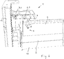
Figur 4- eine Schnittansicht durch die erfindungsgemäße Absturzsicherung aus der
Figur 1 Figur 5- eine alternative Gestaltung einer erfindungsgemäßen Absturzsicherung;
Figur 6- eine schematische Schnittansicht durch die Absturzsicherung aus der
Figur 5 Figur 7- ein erfindungsgemäßes Hubtor mit einer Absturzsicherung.
- figure 1
- a three-dimensional view of an embodiment of a fall protection according to the invention;
- figure 2
- a section of the fall protection from the
figure 1 ; - figure 3
- a plan view from above of a fall protection according to the invention;
- figure 4
- a sectional view through the fall protection according to the invention from
figure 1 ; - figure 5
- an alternative design of a fall protection according to the invention;
- figure 6
- a schematic sectional view through the fall protection from FIG
figure 5 ; - figure 7
- a lifting gate according to the invention with a fall protection.
In der
Die Verriegelungseinrichtung 1 umfasst ferner eine am Torträger 2 angeschlossene Klinke 4, die in den mechanisch verriegelten Eingriff mit dem Stützelement 3 verschwenkbar ist. Im gezeigten Ausführungsbeispiel umfasst die Klinke 4 einen Bolzen 4.2, der in ein Maul 3.2 oder eine Aussparung des Stützelementes 3 einhakbar ist.The
Auf dem Torträger 2 ist ein Anschlagelement 5 einfederbar gelagert, dass eine Führung 6 aufweist, in der die Klinke 4 derart geführt ist, dass sie in Richtung des Stützelementes 3 verschwenkt wird, wenn das Anschlagelement 5 in Richtung des Torträgers 2 eingefedert wird.A
Im gezeigten Ausführungsbeispiel umfasst die Führung 6 eine Kulisse 6.1, mit der ein an der Klinke 4 angeschlossener Kulissenstein 8 im Eingriff steht, um die Verschwenkbewegung der Klinke 4 zu erzwingen, wenn das Anschlagelement 5 auf den Torträger 2 zu bewegt wird.In the exemplary embodiment shown, the
Der Torträger 2 ist zusammen mit einem Hubtor 10, dessen oberes Ende den Torträger 2 ausbildet oder an dessen oberen Ende der Torträger 2 angeschlossen ist, verschiebbar in zwei seitlichen Torführungen 13 gelagert, die sich in der Vertikalrichtung Z erstrecken. Am oberen Ende der seitlichen Torführungen 13 ist jeweils ein Anschlag 7 vorgesehen, an welchem das Anschlagelement 5 anschlägt, wenn sich das Hubtor 10 beziehungsweise der Torträger 2 in seine obere Endlage bewegt. Bei der Bewegung in Richtung der Endlage schlägt zunächst das Anschlagelement 5 am Anschlag 7 an und wird dadurch in seiner Bewegung in der Vertikalrichtung Z gestoppt, wohingegen der Torträger 2, der angetrieben wird, weiter nach oben in der Vertikalrichtung Z bewegt wird. Das Anschlagelement 5 federt entgegen der Kraft der wenigstens einen Druckfeder 9, mit welcher es auf dem Torträger 2 gelagert ist, in Richtung des Torträgers 2 ein. Bei dieser Einfederbewegung zwingt die Kulisse 6.1 den Kulissenstein 8 in einer Richtung quer zur Vertikalrichtung Z nach außen. Dadurch wird die Klinke 4 nach außen in Richtung des Stützelementes 3 verschwenkt und mit ihrem Bolzen 4.2 in einen Bereich oberhalb des Maules 3.2 im Stützelementes 3 verbracht oder unmittelbar in das Maul 3.2 eingesetzt. Die hier nicht näher gezeigte Antriebseinrichtung wird abgeschaltet und das Hubtor 10 beziehungsweise der Torträger 2 befindet sich in seiner oberen Endlage.The
Zum einen wird das Hubtor 10 beziehungsweise der Torträger 2 durch die Antriebseinrichtung in der oberen Endlage gehalten, weil die Antriebseinrichtung eine entsprechende Selbsthemmung aufweist. Diese Selbsthemmung ist in der Regel jedoch nicht groß genug, um eine vergleichsweise große nach unten gerichtete Kraft, die auf den Hubtor 10 ausgeübt wird, abzustützen. Eine solche vergleichsweise große Kraft kann beispielsweise durch einen Einschlag eines Roboterarmes von oben auf den Torträger 2 beziehungsweise das Anschlagelement 5 ausgeübt werden und ohne die Absturzsicherung würde das Hubtor 10 heruntergeschlagen werden.On the one hand, the lifting
Aufgrund dessen, dass sich der Bolzen 4.2 im Maul 3.2 oder oberhalb des Maules 3.2 befindet, führt eine solche Krafteinwirkung von oben jedoch dazu, dass der Torträger 2 sicher in der oberen Position verriegelt ist oder verriegelt wird und das Hubtor 10 entsprechend gehalten wird.Due to the fact that the bolt 4.2 is in the mouth 3.2 or above the mouth 3.2, such an application of force from above results in the
Wenn hingegen eine Antriebseinrichtung am Torträger 2 angreift und auf diesen eine Kraft in der Vertikalrichtung Z nach unten ausübt, so verfährt der Torträger 2 nach unten und die Druckfeder 9 federt aus, wodurch das Anschlagelement 5 zunächst noch am Anschlag 7 gehalten wird, sodass sich der Torträger 2 vom Anschlagelement 5 entfernt. Hierdurch wird der Kulissenstein 8 in der Kulisse 6.1 nach innen bewegt und die Klinke 4 wird aus ihrer Position mit dem Bolzen 4.2 über oder in dem Maul 3.2 entfernt und nach innen verschwenkt, sodass im Anschluss der Torträger 2 zusammen mit dem Anschlagelement 5 nach unten bewegt werden kann.If, on the other hand, a drive device acts on the
Die Ausgestaltung gemäß den
Im hier gezeigten Ausführungsbeispiel ist die Klinke 4 gelenkig um die Drehachse Y am Torträger 2 angeschlossen, sodass sie eine reine Drehbewegung ausführt. Es könnte jedoch auch eine andere Lagerung vorgesehen sein.In the exemplary embodiment shown here, the
Der Anschlag 7 wird durch ein in der Vertikalrichtung Z federnd gelagertes Bauteil, hier einen Gummipuffer, gebildet. Wenn das Anschlagelement 5 am Anschlag 7 anschlägt und anschließend entgegen der Druckfeder 9 eingefedert ist, ermöglicht die Anschlagdruckfeder 7.1, dass, falls eine Antriebseinrichtung den Torträger 2 weiter nach oben bewegt, der Anschlag 7 in der Vertikalrichtung Z nachgibt beziehungsweise verschoben wird, um eine Beschädigung der Antriebseinrichtung oder der mechanischen Verriegelungseinrichtung 1 zu verhindern.The
Die Anschlagdruckfeder 7.1 weist eine größere Federkraft als die Druckfeder 9 auf, um sicherzustellen, dass zunächst die Druckfeder 9 einfedert, bevor die Anschlagdruckfeder 7.1 einfedert.The stop compression spring 7.1 has a greater spring force than the
In der
- 11
- Mechanische VerriegelungseinrichtungMechanical locking device
- 22
- Torträgergate bearer
- 33
- Stützelementsupport element
- 3.13.1
- Bolzenbolt
- 3.23.2
- Maulmouth
- 44
- Klinkepawl
- 4.14.1
- Maulmouth
- 4.24.2
- Bolzenbolt
- 55
- Anschlagelementstop element
- 66
- Führungguide
- 6.16.1
- Kulissebackdrop
- 77
- Anschlagattack
- 7.17.1
- Anschlagdruckfederstop pressure spring
- 88th
- Kulissensteinsliding block
- 99
- Druckfedercompression spring
- 1010
- Hubtorlifting gate
- 1111
- Torfeldgoal field
- 1212
- Antriebseinrichtungdrive device
- 1313
- Seitliche TorführungLateral gate guidance
- ZZ
- Vertikalrichtungvertical direction
- YY
- Drehachseaxis of rotation
Claims (11)
- Anti-fall device for a lifting gate (10), in particular a machine protection lifting gate, having a mechanical locking device (1), which comprises a gate carrier (2) movable in a vertical direction (Z) for joint movement with the lifting gate (10) and a support element (3) stationary in the vertical direction (Z), which can be brought into a mechanically locked engagement with one another, blocking a vertical movement of the gate carrier (2); wherein the locking device (1) furthermore has at least one latch (4) which is connected in an articulated manner, at least indirectly, to the gate carrier (2) and can be pivoted into the mechanically locking engagement with the support element (3), and a stop element (5) is mounted on the gate carrier (2) in a spring-loaded manner, which stop element (5) has a guide (6) in which the latch (4) is guided in such a way that it is pivoted in the direction of the support element (3) when the stop element (5) is deflected, wherein the stop element (5) is assigned a stop (7) in a predetermined vertical end position, against which the stop element (5) strikes during a vertical movement of the gate carrier (2).
- Anti-fall device according to claim 1, characterized in that the support element (3) comprises a bolt (3.1) and the latch (4) has a mouth (4.1) which can be hooked onto the bolt (3.1) by pivoting the latch (4).
- Anti-fall device according to claim 1, characterized in that the support element (3) comprises a mouth (3.2) or a recess and the latch (4) has a bolt (4.2) which can be hooked into the mouth (3.2) or the recess by pivoting the latch (4).
- Anti-fall device according to one of claims 1 to 3, characterized in that the guide (6) comprises a connecting link (6.1) with which a sliding block (8) connected to the latch (4) is in engagement.
- Anti-fall device according to one of claims 1 to 4, characterized in that the latch (4) is connected at least indirectly to the gate carrier (2) so as to be rotatable about a horizontal axis of rotation (Y).
- Anti-fall device according to one of claims 1 to 5, characterized in that the stop (7) is mounted so as to be displaceable in the vertical direction (Z) against a spring force.
- Anti-fall device according to one of claims 1 to 6, characterized in that the stop element (5) completely covers the gate carrier (2) on its upper side.
- Anti-fall device according to one of claims 1 to 7, characterized in that the stop element (5) is mounted on the gate carrier (2) by means of at least one compression spring (9), in particular with a plurality of compression springs (9).
- Lifting gate (10) having at least one gate panel (11) and a drive device (12) for moving the gate panel (11) up and down in a vertical direction (Z), characterized by an anti-fall device according to one of claims 1 to 8, the gate carrier (2) of which is connected to the gate panel (11) or is formed thereby.
- Lifting gate (10) according to claim 9, characterized in that the drive device (12) is connected to the gate panel (11) and/or to the gate carrier (2) vertically below the stop element (5) and decoupled from the stop element (5).
- Lifting gate (10) according to one of claims 9 or 10, characterized in that the drive device (12) comprises a chain drive or belt drive which is connected to the gate panel (11) and/or to the gate carrier (2).
Applications Claiming Priority (1)
| Application Number | Priority Date | Filing Date | Title |
|---|---|---|---|
| DE102019208180.0A DE102019208180B3 (en) | 2019-06-05 | 2019-06-05 | Fall protection for a lifting gate, especially a machine protection lifting gate |
Publications (2)
| Publication Number | Publication Date |
|---|---|
| EP3748112A1 EP3748112A1 (en) | 2020-12-09 |
| EP3748112B1 true EP3748112B1 (en) | 2022-10-19 |
Family
ID=70740487
Family Applications (1)
| Application Number | Title | Priority Date | Filing Date |
|---|---|---|---|
| EP20175158.3A Active EP3748112B1 (en) | 2019-06-05 | 2020-05-18 | Anti-fall device for a lift gate, in particular for protecting machinery |
Country Status (4)
| Country | Link |
|---|---|
| EP (1) | EP3748112B1 (en) |
| DE (1) | DE102019208180B3 (en) |
| ES (1) | ES2932617T3 (en) |
| HU (1) | HUE060755T2 (en) |
Families Citing this family (2)
| Publication number | Priority date | Publication date | Assignee | Title |
|---|---|---|---|---|
| US12410647B2 (en) * | 2022-10-11 | 2025-09-09 | Clopay Corporation | Door stop mechanism |
| US12392184B2 (en) * | 2022-10-11 | 2025-08-19 | Cornellcookson, Llc | Sectional door braking system |
Citations (1)
| Publication number | Priority date | Publication date | Assignee | Title |
|---|---|---|---|---|
| JPS5661693U (en) * | 1979-10-16 | 1981-05-25 |
Family Cites Families (4)
| Publication number | Priority date | Publication date | Assignee | Title |
|---|---|---|---|---|
| DE341009C (en) * | ||||
| DE4024666C2 (en) * | 1990-06-01 | 1994-02-03 | Niemetz Torbau Und Metallbau | Sectional gate |
| JP2554234Y2 (en) * | 1993-12-27 | 1997-11-17 | 三和シヤッター工業株式会社 | Obstacle Detector for Electric Shutter for Construction |
| DK0721043T3 (en) * | 1995-01-05 | 1999-10-25 | Marantec Antrieb Steuerung | Device for monitoring a pulling rope of a gate surface |
-
2019
- 2019-06-05 DE DE102019208180.0A patent/DE102019208180B3/en not_active Expired - Fee Related
-
2020
- 2020-05-18 EP EP20175158.3A patent/EP3748112B1/en active Active
- 2020-05-18 ES ES20175158T patent/ES2932617T3/en active Active
- 2020-05-18 HU HUE20175158A patent/HUE060755T2/en unknown
Patent Citations (1)
| Publication number | Priority date | Publication date | Assignee | Title |
|---|---|---|---|---|
| JPS5661693U (en) * | 1979-10-16 | 1981-05-25 |
Also Published As
| Publication number | Publication date |
|---|---|
| HUE060755T2 (en) | 2023-04-28 |
| ES2932617T3 (en) | 2023-01-23 |
| DE102019208180B3 (en) | 2020-08-20 |
| EP3748112A1 (en) | 2020-12-09 |
Similar Documents
| Publication | Publication Date | Title |
|---|---|---|
| EP1541518B1 (en) | Door drive device for an elevator | |
| EP2399826B1 (en) | Fixing device for at least partial securing of a first and a second item of freight | |
| EP3417134B1 (en) | Fitting assembly for the connection of a tilt and slide leaf | |
| WO2017036795A1 (en) | Device for positioning two sliding doors and furniture | |
| EP0151427B1 (en) | Spring monitoring device | |
| DE202015006895U1 (en) | Adjustable flap hinge | |
| DE3710237A1 (en) | Catching device for doors opening upwards | |
| EP3748112A1 (en) | Anti-fall device for a lift gate, in particular for protecting machinery | |
| DE202010005519U1 (en) | Lock for turnout devices | |
| DE102007032059A1 (en) | Safety locking system for mechanical manipulators | |
| EP0279929A2 (en) | Fall protection device | |
| EP0556632B1 (en) | Horizontal roller door | |
| EP2843169A1 (en) | Support system for a sliding door, and sliding door | |
| EP3106738B1 (en) | Device for moving and fastening a door | |
| EP2848854B1 (en) | Device for locking a movable component | |
| EP0921970B1 (en) | Vehicle with device for securing an object | |
| DE202015004325U1 (en) | Locking device for one or more nose flaps, in particular for rail vehicles | |
| DE202019102262U1 (en) | Stop buffer for a hoist, especially chain hoist, and hoist hereby | |
| DE9214278U1 (en) | Safety device for gates or similar | |
| EP4230892B1 (en) | Boarding bridge | |
| DE10339506B4 (en) | lifting door | |
| EP1957739B1 (en) | Edge protection device | |
| DE102010009064B4 (en) | lock assembly | |
| EP3181507A2 (en) | Safety device for preventing uncontrolled movements of loads | |
| EP1497522B1 (en) | Sectional door and guide assembly therefor |
Legal Events
| Date | Code | Title | Description |
|---|---|---|---|
| PUAI | Public reference made under article 153(3) epc to a published international application that has entered the european phase |
Free format text: ORIGINAL CODE: 0009012 |
|
| STAA | Information on the status of an ep patent application or granted ep patent |
Free format text: STATUS: THE APPLICATION HAS BEEN PUBLISHED |
|
| AK | Designated contracting states |
Kind code of ref document: A1 Designated state(s): AL AT BE BG CH CY CZ DE DK EE ES FI FR GB GR HR HU IE IS IT LI LT LU LV MC MK MT NL NO PL PT RO RS SE SI SK SM TR |
|
| AX | Request for extension of the european patent |
Extension state: BA ME |
|
| STAA | Information on the status of an ep patent application or granted ep patent |
Free format text: STATUS: REQUEST FOR EXAMINATION WAS MADE |
|
| 17P | Request for examination filed |
Effective date: 20210126 |
|
| RBV | Designated contracting states (corrected) |
Designated state(s): AL AT BE BG CH CY CZ DE DK EE ES FI FR GB GR HR HU IE IS IT LI LT LU LV MC MK MT NL NO PL PT RO RS SE SI SK SM TR |
|
| GRAP | Despatch of communication of intention to grant a patent |
Free format text: ORIGINAL CODE: EPIDOSNIGR1 |
|
| STAA | Information on the status of an ep patent application or granted ep patent |
Free format text: STATUS: GRANT OF PATENT IS INTENDED |
|
| INTG | Intention to grant announced |
Effective date: 20220111 |
|
| GRAJ | Information related to disapproval of communication of intention to grant by the applicant or resumption of examination proceedings by the epo deleted |
Free format text: ORIGINAL CODE: EPIDOSDIGR1 |
|
| STAA | Information on the status of an ep patent application or granted ep patent |
Free format text: STATUS: REQUEST FOR EXAMINATION WAS MADE |
|
| GRAP | Despatch of communication of intention to grant a patent |
Free format text: ORIGINAL CODE: EPIDOSNIGR1 |
|
| STAA | Information on the status of an ep patent application or granted ep patent |
Free format text: STATUS: GRANT OF PATENT IS INTENDED |
|
| INTC | Intention to grant announced (deleted) | ||
| INTG | Intention to grant announced |
Effective date: 20220506 |
|
| GRAS | Grant fee paid |
Free format text: ORIGINAL CODE: EPIDOSNIGR3 |
|
| GRAA | (expected) grant |
Free format text: ORIGINAL CODE: 0009210 |
|
| STAA | Information on the status of an ep patent application or granted ep patent |
Free format text: STATUS: THE PATENT HAS BEEN GRANTED |
|
| AK | Designated contracting states |
Kind code of ref document: B1 Designated state(s): AL AT BE BG CH CY CZ DE DK EE ES FI FR GB GR HR HU IE IS IT LI LT LU LV MC MK MT NL NO PL PT RO RS SE SI SK SM TR |
|
| REG | Reference to a national code |
Ref country code: GB Ref legal event code: FG4D Free format text: NOT ENGLISH |
|
| REG | Reference to a national code |
Ref country code: CH Ref legal event code: EP |
|
| REG | Reference to a national code |
Ref country code: DE Ref legal event code: R096 Ref document number: 502020001854 Country of ref document: DE |
|
| REG | Reference to a national code |
Ref country code: IE Ref legal event code: FG4D Free format text: LANGUAGE OF EP DOCUMENT: GERMAN |
|
| REG | Reference to a national code |
Ref country code: AT Ref legal event code: REF Ref document number: 1525639 Country of ref document: AT Kind code of ref document: T Effective date: 20221115 |
|
| REG | Reference to a national code |
Ref country code: ES Ref legal event code: FG2A Ref document number: 2932617 Country of ref document: ES Kind code of ref document: T3 Effective date: 20230123 |
|
| REG | Reference to a national code |
Ref country code: SK Ref legal event code: T3 Ref document number: E 40894 Country of ref document: SK |
|
| REG | Reference to a national code |
Ref country code: LT Ref legal event code: MG9D |
|
| REG | Reference to a national code |
Ref country code: NL Ref legal event code: MP Effective date: 20221019 |
|
| PG25 | Lapsed in a contracting state [announced via postgrant information from national office to epo] |
Ref country code: NL Free format text: LAPSE BECAUSE OF FAILURE TO SUBMIT A TRANSLATION OF THE DESCRIPTION OR TO PAY THE FEE WITHIN THE PRESCRIBED TIME-LIMIT Effective date: 20221019 |
|
| PG25 | Lapsed in a contracting state [announced via postgrant information from national office to epo] |
Ref country code: SE Free format text: LAPSE BECAUSE OF FAILURE TO SUBMIT A TRANSLATION OF THE DESCRIPTION OR TO PAY THE FEE WITHIN THE PRESCRIBED TIME-LIMIT Effective date: 20221019 Ref country code: PT Free format text: LAPSE BECAUSE OF FAILURE TO SUBMIT A TRANSLATION OF THE DESCRIPTION OR TO PAY THE FEE WITHIN THE PRESCRIBED TIME-LIMIT Effective date: 20230220 Ref country code: NO Free format text: LAPSE BECAUSE OF FAILURE TO SUBMIT A TRANSLATION OF THE DESCRIPTION OR TO PAY THE FEE WITHIN THE PRESCRIBED TIME-LIMIT Effective date: 20230119 Ref country code: LT Free format text: LAPSE BECAUSE OF FAILURE TO SUBMIT A TRANSLATION OF THE DESCRIPTION OR TO PAY THE FEE WITHIN THE PRESCRIBED TIME-LIMIT Effective date: 20221019 Ref country code: FI Free format text: LAPSE BECAUSE OF FAILURE TO SUBMIT A TRANSLATION OF THE DESCRIPTION OR TO PAY THE FEE WITHIN THE PRESCRIBED TIME-LIMIT Effective date: 20221019 |
|
| REG | Reference to a national code |
Ref country code: HU Ref legal event code: AG4A Ref document number: E060755 Country of ref document: HU |
|
| PG25 | Lapsed in a contracting state [announced via postgrant information from national office to epo] |
Ref country code: RS Free format text: LAPSE BECAUSE OF FAILURE TO SUBMIT A TRANSLATION OF THE DESCRIPTION OR TO PAY THE FEE WITHIN THE PRESCRIBED TIME-LIMIT Effective date: 20221019 Ref country code: PL Free format text: LAPSE BECAUSE OF FAILURE TO SUBMIT A TRANSLATION OF THE DESCRIPTION OR TO PAY THE FEE WITHIN THE PRESCRIBED TIME-LIMIT Effective date: 20221019 Ref country code: LV Free format text: LAPSE BECAUSE OF FAILURE TO SUBMIT A TRANSLATION OF THE DESCRIPTION OR TO PAY THE FEE WITHIN THE PRESCRIBED TIME-LIMIT Effective date: 20221019 Ref country code: IS Free format text: LAPSE BECAUSE OF FAILURE TO SUBMIT A TRANSLATION OF THE DESCRIPTION OR TO PAY THE FEE WITHIN THE PRESCRIBED TIME-LIMIT Effective date: 20230219 Ref country code: HR Free format text: LAPSE BECAUSE OF FAILURE TO SUBMIT A TRANSLATION OF THE DESCRIPTION OR TO PAY THE FEE WITHIN THE PRESCRIBED TIME-LIMIT Effective date: 20221019 Ref country code: GR Free format text: LAPSE BECAUSE OF FAILURE TO SUBMIT A TRANSLATION OF THE DESCRIPTION OR TO PAY THE FEE WITHIN THE PRESCRIBED TIME-LIMIT Effective date: 20230120 |
|
| REG | Reference to a national code |
Ref country code: DE Ref legal event code: R097 Ref document number: 502020001854 Country of ref document: DE |
|
| PG25 | Lapsed in a contracting state [announced via postgrant information from national office to epo] |
Ref country code: SM Free format text: LAPSE BECAUSE OF FAILURE TO SUBMIT A TRANSLATION OF THE DESCRIPTION OR TO PAY THE FEE WITHIN THE PRESCRIBED TIME-LIMIT Effective date: 20221019 Ref country code: RO Free format text: LAPSE BECAUSE OF FAILURE TO SUBMIT A TRANSLATION OF THE DESCRIPTION OR TO PAY THE FEE WITHIN THE PRESCRIBED TIME-LIMIT Effective date: 20221019 Ref country code: EE Free format text: LAPSE BECAUSE OF FAILURE TO SUBMIT A TRANSLATION OF THE DESCRIPTION OR TO PAY THE FEE WITHIN THE PRESCRIBED TIME-LIMIT Effective date: 20221019 Ref country code: DK Free format text: LAPSE BECAUSE OF FAILURE TO SUBMIT A TRANSLATION OF THE DESCRIPTION OR TO PAY THE FEE WITHIN THE PRESCRIBED TIME-LIMIT Effective date: 20221019 |
|
| PLBE | No opposition filed within time limit |
Free format text: ORIGINAL CODE: 0009261 |
|
| STAA | Information on the status of an ep patent application or granted ep patent |
Free format text: STATUS: NO OPPOSITION FILED WITHIN TIME LIMIT |
|
| PG25 | Lapsed in a contracting state [announced via postgrant information from national office to epo] |
Ref country code: AL Free format text: LAPSE BECAUSE OF FAILURE TO SUBMIT A TRANSLATION OF THE DESCRIPTION OR TO PAY THE FEE WITHIN THE PRESCRIBED TIME-LIMIT Effective date: 20221019 |
|
| 26N | No opposition filed |
Effective date: 20230720 |
|
| PG25 | Lapsed in a contracting state [announced via postgrant information from national office to epo] |
Ref country code: SI Free format text: LAPSE BECAUSE OF FAILURE TO SUBMIT A TRANSLATION OF THE DESCRIPTION OR TO PAY THE FEE WITHIN THE PRESCRIBED TIME-LIMIT Effective date: 20221019 |
|
| P01 | Opt-out of the competence of the unified patent court (upc) registered |
Effective date: 20231117 |
|
| REG | Reference to a national code |
Ref country code: CH Ref legal event code: PL |
|
| PG25 | Lapsed in a contracting state [announced via postgrant information from national office to epo] |
Ref country code: MC Free format text: LAPSE BECAUSE OF FAILURE TO SUBMIT A TRANSLATION OF THE DESCRIPTION OR TO PAY THE FEE WITHIN THE PRESCRIBED TIME-LIMIT Effective date: 20221019 |
|
| REG | Reference to a national code |
Ref country code: BE Ref legal event code: MM Effective date: 20230531 |
|
| PG25 | Lapsed in a contracting state [announced via postgrant information from national office to epo] |
Ref country code: MC Free format text: LAPSE BECAUSE OF FAILURE TO SUBMIT A TRANSLATION OF THE DESCRIPTION OR TO PAY THE FEE WITHIN THE PRESCRIBED TIME-LIMIT Effective date: 20221019 Ref country code: LU Free format text: LAPSE BECAUSE OF NON-PAYMENT OF DUE FEES Effective date: 20230518 Ref country code: LI Free format text: LAPSE BECAUSE OF NON-PAYMENT OF DUE FEES Effective date: 20230531 Ref country code: CH Free format text: LAPSE BECAUSE OF NON-PAYMENT OF DUE FEES Effective date: 20230531 |
|
| REG | Reference to a national code |
Ref country code: IE Ref legal event code: MM4A |
|
| PG25 | Lapsed in a contracting state [announced via postgrant information from national office to epo] |
Ref country code: IE Free format text: LAPSE BECAUSE OF NON-PAYMENT OF DUE FEES Effective date: 20230518 |
|
| PG25 | Lapsed in a contracting state [announced via postgrant information from national office to epo] |
Ref country code: IE Free format text: LAPSE BECAUSE OF NON-PAYMENT OF DUE FEES Effective date: 20230518 |
|
| PG25 | Lapsed in a contracting state [announced via postgrant information from national office to epo] |
Ref country code: IT Free format text: LAPSE BECAUSE OF FAILURE TO SUBMIT A TRANSLATION OF THE DESCRIPTION OR TO PAY THE FEE WITHIN THE PRESCRIBED TIME-LIMIT Effective date: 20221019 Ref country code: BE Free format text: LAPSE BECAUSE OF NON-PAYMENT OF DUE FEES Effective date: 20230531 |
|
| PG25 | Lapsed in a contracting state [announced via postgrant information from national office to epo] |
Ref country code: BG Free format text: LAPSE BECAUSE OF FAILURE TO SUBMIT A TRANSLATION OF THE DESCRIPTION OR TO PAY THE FEE WITHIN THE PRESCRIBED TIME-LIMIT Effective date: 20221019 |
|
| PG25 | Lapsed in a contracting state [announced via postgrant information from national office to epo] |
Ref country code: BG Free format text: LAPSE BECAUSE OF FAILURE TO SUBMIT A TRANSLATION OF THE DESCRIPTION OR TO PAY THE FEE WITHIN THE PRESCRIBED TIME-LIMIT Effective date: 20221019 |
|
| GBPC | Gb: european patent ceased through non-payment of renewal fee |
Effective date: 20240518 |
|
| PG25 | Lapsed in a contracting state [announced via postgrant information from national office to epo] |
Ref country code: GB Free format text: LAPSE BECAUSE OF NON-PAYMENT OF DUE FEES Effective date: 20240518 |
|
| PG25 | Lapsed in a contracting state [announced via postgrant information from national office to epo] |
Ref country code: CY Free format text: LAPSE BECAUSE OF FAILURE TO SUBMIT A TRANSLATION OF THE DESCRIPTION OR TO PAY THE FEE WITHIN THE PRESCRIBED TIME-LIMIT; INVALID AB INITIO Effective date: 20200518 |
|
| PG25 | Lapsed in a contracting state [announced via postgrant information from national office to epo] |
Ref country code: TR Free format text: LAPSE BECAUSE OF FAILURE TO SUBMIT A TRANSLATION OF THE DESCRIPTION OR TO PAY THE FEE WITHIN THE PRESCRIBED TIME-LIMIT Effective date: 20221019 |
|
| PGFP | Annual fee paid to national office [announced via postgrant information from national office to epo] |
Ref country code: HU Payment date: 20260424 Year of fee payment: 7 |
|
| PGFP | Annual fee paid to national office [announced via postgrant information from national office to epo] |
Ref country code: ES Payment date: 20260601 Year of fee payment: 7 |
|
| PGFP | Annual fee paid to national office [announced via postgrant information from national office to epo] |
Ref country code: DE Payment date: 20260615 Year of fee payment: 7 |
|
| PGFP | Annual fee paid to national office [announced via postgrant information from national office to epo] |
Ref country code: AT Payment date: 20260520 Year of fee payment: 7 |
|
| PGFP | Annual fee paid to national office [announced via postgrant information from national office to epo] |
Ref country code: CZ Payment date: 20260423 Year of fee payment: 7 |
|
| PGFP | Annual fee paid to national office [announced via postgrant information from national office to epo] |
Ref country code: FR Payment date: 20260528 Year of fee payment: 7 |
|
| PGFP | Annual fee paid to national office [announced via postgrant information from national office to epo] |
Ref country code: SK Payment date: 20260424 Year of fee payment: 7 |