EP3748115A1 - Bodenschwelle für eine schiebetür - Google Patents
Bodenschwelle für eine schiebetür Download PDFInfo
- Publication number
- EP3748115A1 EP3748115A1 EP20170003.6A EP20170003A EP3748115A1 EP 3748115 A1 EP3748115 A1 EP 3748115A1 EP 20170003 A EP20170003 A EP 20170003A EP 3748115 A1 EP3748115 A1 EP 3748115A1
- Authority
- EP
- European Patent Office
- Prior art keywords
- cover
- base body
- profile
- threshold according
- track
- Prior art date
- Legal status (The legal status is an assumption and is not a legal conclusion. Google has not performed a legal analysis and makes no representation as to the accuracy of the status listed.)
- Granted
Links
Images


Classifications
-
- E—FIXED CONSTRUCTIONS
- E06—DOORS, WINDOWS, SHUTTERS, OR ROLLER BLINDS IN GENERAL; LADDERS
- E06B—FIXED OR MOVABLE CLOSURES FOR OPENINGS IN BUILDINGS, VEHICLES, FENCES OR LIKE ENCLOSURES IN GENERAL, e.g. DOORS, WINDOWS, BLINDS, GATES
- E06B1/00—Border constructions of openings in walls, floors, or ceilings; Frames to be rigidly mounted in such openings
- E06B1/70—Sills; Thresholds
-
- E—FIXED CONSTRUCTIONS
- E06—DOORS, WINDOWS, SHUTTERS, OR ROLLER BLINDS IN GENERAL; LADDERS
- E06B—FIXED OR MOVABLE CLOSURES FOR OPENINGS IN BUILDINGS, VEHICLES, FENCES OR LIKE ENCLOSURES IN GENERAL, e.g. DOORS, WINDOWS, BLINDS, GATES
- E06B3/00—Window sashes, door leaves, or like elements for closing wall or like openings; Layout of fixed or moving closures, e.g. windows in wall or like openings; Features of rigidly-mounted outer frames relating to the mounting of wing frames
- E06B3/32—Arrangements of wings characterised by the manner of movement; Arrangements of movable wings in openings; Features of wings or frames relating solely to the manner of movement of the wing
- E06B3/34—Arrangements of wings characterised by the manner of movement; Arrangements of movable wings in openings; Features of wings or frames relating solely to the manner of movement of the wing with only one kind of movement
- E06B3/42—Sliding wings; Details of frames with respect to guiding
- E06B3/46—Horizontally-sliding wings
- E06B3/4636—Horizontally-sliding wings for doors
-
- E—FIXED CONSTRUCTIONS
- E06—DOORS, WINDOWS, SHUTTERS, OR ROLLER BLINDS IN GENERAL; LADDERS
- E06B—FIXED OR MOVABLE CLOSURES FOR OPENINGS IN BUILDINGS, VEHICLES, FENCES OR LIKE ENCLOSURES IN GENERAL, e.g. DOORS, WINDOWS, BLINDS, GATES
- E06B1/00—Border constructions of openings in walls, floors, or ceilings; Frames to be rigidly mounted in such openings
- E06B1/70—Sills; Thresholds
- E06B2001/707—Thresholds with special provision for insulation
Definitions
- the present invention relates to a threshold for a sliding door, in particular a lift-and-slide door, with a strip-shaped base body made of a rigid foam material, on the top of which a cover with at least one track for the sliding door is arranged.
- the EP 3 225 771 A1 discloses a threshold for a sliding door which has a threshold profile designed as a hollow profile, on the upper side of which at least one track for a sliding sash is provided.
- strips made of hard foam can be used, which are arranged below the threshold in order to reduce the heat transfer in this area.
- the disadvantage of this construction is that there is a certain amount of heat conduction via the threshold, since this usually consists of metal or a plastic with good thermal conductivity.
- a strip-shaped base body made of a rigid foam material is provided, on the upper side of which a cover is provided which is single-walled at least in the area of the track without a hollow chamber and rests positively on the upper side of the base body.
- a cover is provided which is single-walled at least in the area of the track without a hollow chamber and rests positively on the upper side of the base body.
- the base body preferably has a profiled upper side, the cover having a geometry that is adapted to the contour of the upper side.
- the base body can, for example, have a groove into which a groove-shaped recess of the cover is inserted, for example in order to form a track.
- one or more steps can be formed on the base body on which profiles of the cover can be fixed.
- the cover can be mounted on the base body essentially without any gaps.
- at least the profile of the cover that forms the track is arranged directly on an upper side of the base body, so that mechanical loads through the sliding door can be removed via the track into the base body made of a rigid foam material.
- This profile of the cover can be glued to the base body and optionally encompass a strip-shaped projection on the base body in a U-shape.
- the base body is preferably made of an extruded rigid foam material.
- the base body can be made from a single material or different materials.
- Various rigid foams with different strengths are preferably provided, so that areas subject to higher loads, for example below the running track, have a higher strength than other areas, for example under a profile of the step protection.
- Materials of higher strength can be special rigid foam materials made of plastic, while softer materials can be made of expanded polystyrene.
- Harder materials can include polyurethane foams, for example.
- the cover preferably comprises several profiles, which can be made of different materials.
- a profile is preferably made of aluminum as a cover profile for the step protection.
- the area of the step protection is the area in which the user steps on the threshold, but which does not form the at least one track for the sliding door.
- the track for the sliding door is preferably formed on a different profile than the step protection, it being possible for the profile with the track to be made of plastic, in particular a hard plastic such as PVC.
- This plastic profile is preferably glued to the base body.
- the profile can be thin-walled, for example less than 3 mm thick, in order to keep the heat losses low.
- the cover can furthermore comprise at least two profiles which are connected to one another via an elastic sealing means, for example an EPDM seal.
- an elastic sealing means for example an EPDM seal.
- a seal can be provided between two profiles, for example between the profile that forms the running track and a profile for the step protection.
- the cover can also comprise at least three profiles, at least two profiles being partially overlapping, so that the ingress of moisture through the overlapping arrangement is prevented.
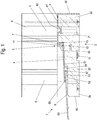
- a threshold 1 comprises a base body 2 which is designed in the form of a strip and preferably extends over the entire length of a window frame in which a sliding door is movably arranged, in particular a lift-and-slide door.
- the base body 2 consists of a rigid foam material.
- a multi-part cover 3, which is formed from individual profiles 4, 5 and 6, is provided on the upper side of the base body 2.
- the base body 2 is connected to posts 8 at opposite ends, in particular via screws 9 which at least partially reach through the base body 2 and are screwed into the post 8.
- the cover 3 comprises a profile 4 on which a track 42 for a sliding door is formed.
- the track 42 is formed by a groove-shaped section and is used to guide rollers of a carriage of the sliding door.
- the profile 4 is essentially angular and comprises a vertical leg 40 and an essentially horizontal leg 41 on which the raceway 42 is formed. On the horizontal leg 41 an angled edge 43 is formed at the end so that a region of the base body 2 is encompassed by the edge 43 and the leg 40.
- the profile 4 is connected to the base body 2 without a gap and is preferably glued to it.
- the profile 4 can be made of a hard plastic material, for example PVC, or of a metal such as aluminum.
- a profile 5 for the step protection Adjacent to the profile 4 is a profile 5 for the step protection, which is made for example of aluminum.
- the profile 5 comprises a substantially horizontal leg 51, which can be arranged slightly inclined to an outer side so that moisture can flow off better.
- a downwardly projecting web 52 is inserted in a groove 61 of an adjacent profile 6.
- an end section 53 of the leg 51 is arranged so as to overlap with the profile 6 and is supported thereon via one or more projections.
- the profile 5 is provided with an upwardly projecting edge 50 which is arranged adjacent to the edge 43.
- a sealing means 7 is arranged between the edge 50 and the edge 43, in particular a strip-shaped sealing strip which has at least one sealing lip.
- an upper sealing lip 71 is provided, which rests on an end face of the edge 50, and a lower sealing lip 72, which rests against the edge 50 in a clamping manner.
- the design of the sealing means 7 can also be changed, and other geometries of the sealing strip can be used in order to seal the space between the profile 4 and the profile 5.
- the sealing means 7 prevents direct contact between the metallic profile 5 and the profile 4 made of plastic, so that the thermal insulation is improved.
- a profile 6 is provided, preferably made of aluminum, which is arranged with a section 60 below the profile 5, which serves as a step protection.
- a groove 61 into which the web 52 engages is formed on the section 60.
- the profile 6 has a vertical web 62 which rests on a vertical edge of the base body 2.
- a protruding web 63 is formed on the profile 6, which protrudes over the base body 2.
- the surface on the profile 5 and the profile 6 is arranged slightly inclined to the outside, for example at an angle between 2 ° to 8 °.
- the base body 2 without the cover 3 is shown in detail.
- the base body 2 has a maximum height h and comprises several sections 20 to 24 made of foamed material.
- the middle one can Section 20 and the two end sections 22 and 24 can be made of a first material, for example from foamed polystyrene, while two sections 21 and 23 between the middle section 20 and the two end sections 22 and 24 are made of a material with higher strength, for example made of a foamed material based on polyurethane.
- the sections 21 and 23 with higher strength can be used, for example, to fix the screws 9.
- a groove 25 is formed in the section 21 with higher strength, in which the groove-shaped raceway 42 is arranged, so that weight loads can be introduced directly into the section 21.
- the bottom of the groove 25 is formed essentially from the material of the section 21 with higher strength.
- the base body 2 also has a profile on its upper side, which is formed by several steps 26 and 27.
- the first angular step 26 is used to support the profile 4 in the area of the edge 43.
- the second step 27 is used to position the profile 6, with additional steps or depressions optionally also being able to be provided on the upper side, the contour of the cover 3 in the Essentially the contour of the upper side of the base body 2 is adapted.
- the base body 2 comprises a groove 28 which serves to receive a screw head 10, as shown in FIG Figure 1 is shown.
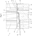
- a modified threshold 1 ' is shown, the cover 3 corresponding to the previous embodiment. Only the strip-shaped base body 2 'was modified, which has a greater height H than the base body 2 in the previous embodiment.
- screws 9 can be screwed, which are fixed to the post 8 of the frame.
- the area of the raceway 42 is arranged above the section 21 'with higher strength.
- the base body 2 ' is shown without the cover 3.
- the base body 2 ' is made from five sections 20' to 24 'and has a groove 25 and steps 26 and 27 on its upper side.
- the height H can be in a range between 50 mm to 150 mm, while the height h of the base body 2 of the Figure 2 in one Range between 30 mm to 80 mm, in particular 40 mm to 60 mm.
- the cover 3 has three profiles 4, 5 and 6. It is of course also possible to provide only two profiles for forming the cover 3 or more than three profiles.
- the cover 3 is single-walled, i.e. without hollow chambers, whereby this design does not exclude that individual sections of a profile overlap, for example those of the profile 5 and 6. However, it is also possible to combine the profiles 5 and 6 into a single profile .
- the base body consists of several sections 20 to 24 or 20 'to 24' which are glued together. It is also possible to produce the sections 20 to 24 and 20 'to 24' by coextrusion. Furthermore, a single material made of a rigid foam can also be used as the base body. Optionally, at least one of the profiles 4, 5 and 6 can be coextruded with the base body 2 or 2 '.
Landscapes
- Engineering & Computer Science (AREA)
- Civil Engineering (AREA)
- Structural Engineering (AREA)
- Wing Frames And Configurations (AREA)
- Specific Sealing Or Ventilating Devices For Doors And Windows (AREA)
Abstract
Description
- Die vorliegende Erfindung betrifft eine Bodenschwelle für eine Schiebetür, insbesondere eine Hebe-Schiebetür, mit einem leistenförmigen Grundkörper aus einem Hartschaummaterial, an dessen Oberseite eine Abdeckung mit mindestens einer Laufbahn für die Schiebetür angeordnet ist.
- Die
EP 3 225 771 A1 offenbart eine Bodenschwelle für eine Schiebetür, die ein als Hohlprofil ausgebildetes Schwellenprofil aufweist, an dessen Oberseite mindestens eine Laufbahn für einen Schiebeflügel vorgesehen ist. Für den Einbau der Bodenschwelle können Leisten aus Hartschaum verwendet werden, die unterhalb der Bodenschwelle angeordnet werden, um den Wärmeübergang in diesem Bereich zu verringern. Nachteilig bei dieser Konstruktion ist, dass über die Bodenschwelle eine gewisse Wärmeleitung erfolgt, da diese meist aus Metall oder einem gut wärmeleitfähigen Kunststoff besteht. - Es ist daher Aufgabe der vorliegenden Erfindung, eine Bodenschwelle für eine Schiebetür zu schaffen, die eine verbesserte Wärmeisolierung bereitstellt und einfach an unterschiedliche Einbausituationen angepasst werden kann.
- Diese Aufgabe wird mit einer Bodenschwelle mit den Merkmalen des Anspruches 1 gelöst.
- Bei der erfindungsgemäßen Bodenschwelle ist ein leistenförmiger Grundkörper aus einem Hartschaummaterial vorgesehen, an dessen Oberseite eine Abdeckung vorgesehen ist, die zumindest im Bereich der Laufbahn einwandig ohne Hohlkammer ausgebildet ist und formschlüssig an der Oberseite des Grundkörpers anliegt. Dadurch wird der Wärmefluss durch die Abdeckung unterhalb des Schiebflügels reduziert, da diese im Bereich der Laufbahn nur einwandig ausgebildet ist und ohne Hohlkammern, so dass diese verglichen mit Hohlkammerprofilen eine bessere Wärmeisolierung ermöglicht. In dem Bereich neben der Schiebetür, also im eingebauten Zustand im Außenbereich, kann die Abdeckung vorzugsweise ebenfalls einwandig und ohne Hohlkammern ausgebildet sein, wobei bei einer mehrteiligen Ausbildung der Abdeckung eine gewisse Überdeckung einzelner Profile nicht als eine Hohlkammer der Abdeckung angesehen wird. Zudem lässt sich die Bodenschwelle an unterschiedliche Einsatzzwecke anpassen, da der leistenförmige Grundkörper aus Hartschaummaterial hergestellt ist und somit einfach in der Höhe modifiziert werden kann.
- Der Grundkörper weist vorzugsweise eine profilierte Oberseite auf, wobei die Abdeckung eine an die Kontur der Oberseite angepasste Geometrie aufweist. Der Grundkörper kann beispielsweise eine Nut aufweisen, in die eine nutförmige Vertiefung der Abdeckung eingefügt ist, beispielsweise um eine Laufbahn auszubilden. Zudem können an dem Grundkörper eine oder mehrere Stufen ausgebildet sein, an denen Profile der Abdeckung fixiert werden können. Die Abdeckung kann dabei im Wesentlichen spaltfrei an dem Grundkörper montiert sein. Vorzugsweise ist zumindest das Profil der Abdeckung, das die Laufbahn ausbildet, unmittelbar an einer Oberseite des Grundkörpers angeordnet, so dass mechanische Belastungen durch die Schiebetür über die Laufbahn in den Grundkörper aus einem Hartschaummaterial abgetragen werden können. Dieses Profil der Abdeckung kann mit dem Grundkörper verklebt sein und optional einen leistenförmigen Vorsprung an dem Grundkörper U-förmig umgreifen.
- Der Grundkörper besteht vorzugsweise aus einem extrudierten Hartschaummaterial. Dabei kann der Grundkörper aus einem einzigen Material oder unterschiedlichen Materialien hergestellt sein. Vorzugsweise sind verschiedene Hartschäume mit unterschiedlichen Festigkeiten vorgesehen, so dass höher belastete Bereiche, beispielsweise unterhalb der Laufbahn, eine höhere Festigkeit besitzen als andere Bereiche, beispielsweise unter einem Profil des Trittschutzes. Materialien höherer Festigkeit können spezielle Hartschaummaterialien aus Kunststoff sein, während weichere Materialien aus geschäumtem Polystyrol hergestellt sein können. Härtere Materialien können beispielsweise Polyurethanschäume umfassen.
- Die Abdeckung umfasst vorzugsweise mehrere Profile, die aus unterschiedlichen Materialien bestehen können. Vorzugsweise ist ein Profil als ein Abdeckprofil für den Trittschutz aus Aluminium hergestellt. Der Bereich des Trittschutzes ist dabei derjenige Bereich, in dem der Benutzer auf die Bodenschwelle tritt, der aber nicht die mindestens eine Laufbahn für die Schiebetür ausbildet. Die Laufbahn für die Schiebetür wird vorzugsweise an einem anderen Profil ausgebildet als der Trittschutz, wobei das Profil mit der Laufbahn aus Kunststoff, insbesondere einem harten Kunststoff, wie PVC, hergestellt sein kann. Dieses Kunststoffprofil ist vorzugsweise mit dem Grundkörper verklebt. Das Profil kann dünnwandig ausgebildet sein, beispielsweise mit einer Dicke geringer 3 mm, um die Wärmeverluste gering zu halten.
- Die Abdeckung kann ferner mindestens zwei Profile umfassen, die über ein elastisches Dichtmittel miteinander verbunden sind, beispielsweise eine Dichtung aus EPDM. Dadurch kann eine Abdichtung zwischen zwei Profilen bereitgestellt werden, beispielsweise zwischen dem Profil, das die Laufbahn ausbildet, und einem Profil für den Trittschutz. Die Abdeckung kann auch mindestens drei Profile umfassen, wobei mindestens zwei Profile teilweise überlappend angeordnet sind, so dass ein Eintritt von Feuchtigkeit durch die überlappende Anordnung verhindert wird.
- Die Erfindung wird nachfolgend anhand zweier Ausführungsbeispiele mit Bezug auf die beigefügten Zeichnungen näher erläutert. Es zeigen:
- Figur 1
- eine Schnittansicht durch eine erfindungsgemäße Bodenschwelle;
- Figur 2
- eine Schnittansicht durch den Grundkörper der Bodenschwelle der
Figur 1 ; - Figur 3
- eine Schnittansicht durch eine modifizierte Bodenschwelle, und
- Figur 4
- eine Schnittansicht durch den Grundkörper der Bodenschwelle der
Figur 3 . - Eine Bodenschwelle 1 umfasst einen Grundkörper 2, der leistenförmig ausgebildet ist und sich vorzugsweise über die gesamte Länge eines Blendrahmens erstreckt, in dem eine Schiebetür bewegbar angeordnet ist, insbesondere eine Hebe-Schiebetür. Der Grundkörper 2 besteht aus einem Hartschaummaterial. An der Oberseite des Grundkörpers 2 ist eine mehrteilige Abdeckung 3 vorgesehen, die aus einzelnen Profilen 4, 5 und 6 gebildet ist. Der Grundkörper 2 ist an gegenüberliegenden Enden mit Pfosten 8 verbunden, insbesondere über Schrauben 9, die den Grundkörper 2 zumindest teilweise durchgreifen und in den Pfosten 8 eingeschraubt sind.
- Die Abdeckung 3 umfasst ein Profil 4, an dem eine Laufbahn 42 für eine Schiebetür ausgebildet ist. Die Laufbahn 42 ist durch einen nutförmigen Abschnitt gebildet und dient zur Führung von Laufrollen eines Laufwagens der Schiebetür. Das Profil 4 ist im Wesentlichen winkelförmig ausgebildet und umfasst einen vertikalen Schenkel 40 und einem in Wesentlichen horizontalen Schenkel 41, an dem die Laufbahn 42 ausgebildet ist. An dem horizontalen Schenkel 41 ist endseitig eine abgewinkelte Kante 43 ausgebildet, so dass ein Bereich des Grundkörpers 2 durch die Kante 43 und den Schenkel 40 umgriffen wird. Das Profil 4 ist spaltfrei mit dem Grundkörper 2 verbunden und vorzugsweise mit diesem verklebt. Das Profil 4 kann aus einem harten Kunststoffmaterial, beispielsweise aus PVC, hergestellt sein, oder aus einem Metall, wie Aluminium.
- Benachbart zu dem Profil 4 ist ein Profil 5 für den Trittschutz vorgesehen, das beispielsweise aus Aluminium hergestellt ist. Das Profil 5 umfasst einen im Wesentlichen horizontalen Schenkel 51, der zu einer Außenseite leicht geneigt angeordnet sein kann, damit Feuchtigkeit besser abströmen kann. An dem Schenkel 51 ist ein nach unten ragender Steg 52 in einer Nut 61 eines benachbarten Profils 6 eingefügt. Ferner ist ein Endabschnitt 53 des Schenkels 51 überlappend mit dem Profil 6 angeordnet und ist über einen oder mehrere Vorsprünge auf diesem abgestützt. Auf der gegenüberliegenden Seite ist das Profil 5 mit einer nach oben ragenden Kante 50 versehen, die benachbart zu der Kante 43 angeordnet ist. Zwischen der Kante 50 und der Kante 43 ist ein Dichtmittel 7 angeordnet, insbesondere ein leistenförmiger Dichtstreifen, der mindestens eine Dichtlippe aufweist. In dem dargestellten Ausführungsbeispiel ist eine obere Dichtlippe 71 vorgesehen, die auf einer Stirnseite der Kante 50 aufliegt und eine unter Dichtlippe 72, die klemmend an der Kante 50 anliegt. Die Gestaltung der Dichtmittel 7 kann auch geändert werden, und es können andere Geometrien des Dichtstreifens eingesetzt werden, um den Zwischenraum zwischen dem Profil 4 und dem Profil 5 abzudichten. Durch das Dichtmittel 7 wird ein unmittelbarer Kontakt zwischen dem metallischen Profil 5 und dem Profil 4 aus Kunststoff verhindert, so dass die Wärmeisolierung verbessert wird.
- Zur Außenseite hin ist ein Profil 6 vorgesehen, vorzugsweise aus Aluminium, das mit einem Abschnitt 60 unterhalb des Profils 5 angeordnet ist, der als Trittschutz dient. An dem Abschnitt 60 ist eine Nut 61 ausgebildet, in die der Steg 52 eingreift. Das Profil 6 weist einen vertikalen Steg 62 auf, der an einer vertikalen Kante des Grundkörpers 2 anliegt. Ferner ist ein hervorstehender Steg 63 an dem Profil 6 ausgebildet, der über den Grundkörper 2 hervorsteht. Die Oberfläche an dem Profil 5 und dem Profil 6 ist zur Außenseite leicht geneigt angeordnet, beispielsweise in einem Winkel zwischen 2° bis 8°.
- In
Figur 2 ist der Grundkörper 2 ohne die Abdeckung 3 im Detail dargestellt. Der Grundkörper 2 besitzt eine maximale Höhe h und umfasst mehrere Abschnitte 20 bis 24 aus geschäumtem Material. Bei speisweise kann der mittlere Abschnitt 20 sowie die beiden endseitigen Abschnitte 22 und 24 aus einem ersten Material hergestellt sein, beispielsweise aus geschäumtem Polystyrol, während zwei Abschnitte 21 und 23 zwischen dem mittleren Abschnitt 20 und den beiden endseitigen Abschnitte 22 und 24 aus einem Material mit höherer Festigkeit sind, beispielsweise aus einem geschäumten Material auf Polyurethanbasis. Die Abschnitte 21 und 23 mit höherer Festigkeit können beispielsweise zur Fixierung der Schrauben 9 dienen. Zudem ist in dem Abschnitt 21 mit höherer Festigkeit eine Nut 25 ausgebildet, in der die nutförmige Laufbahn 42 angeordnet ist, so dass Gewichtslasten unmittelbar in den Abschnitt 21 eingeleitet werden können. Hierfür ist der Boden der Nut 25 im Wesentlichen aus dem Material des Abschnittes 21 mit höherer Festigkeit ausgebildet. - Der Grundkörper 2 weist an seiner Oberseite ferner eine Profilierung auf, die durch mehrere Stufen 26 und 27 gebildet ist. Die erste winkelförmige Stufe 26 dient dabei zur Abstützung des Profils 4 im Bereich der Kante 43. Die zweite Stufe 27 dient zur Positionierung des Profils 6, wobei optional auch weitere Stufen oder Vertiefungen an der Oberseite vorgesehen werden können, wobei die Kontur der Abdeckung 3 im Wesentlichen der Kontur der Oberseite des Grundkörpers 2 angepasst ist. An einer Unterseite umfasst der Grundkörper 2 eine Nut 28, die zur Aufnahme eines Schraubenkopfes 10 dient, wie dies in
Figur 1 gezeigt ist. - In
Figur 3 ist eine modifizierte Bodenschwelle 1' gezeigt, wobei die Abdeckung 3 dem vorangegangenen Ausführungsbeispiel entspricht. Lediglich der leistenförmige Grundkörper 2' wurde modifiziert, der eine größere Höhe H besitzt als der Grundkörper 2 bei dem vorangegangenen Ausführungsbeispiel. Der Grundkörper 2' umfasst einen mittleren Abschnitt 20 sowie endseitigen Abschnitte 22' und 24' aus einem ersten geschäumten Material und dazwischen zwei Abschnitte 21' und 23' aus einem zweiten geschäumten Material, das eine höhere Festigkeit besitzt als das erste Material. In dem geschäumten Material mit höherer Festigkeit können Schrauben 9 eingedreht sein, die an dem Pfosten 8 des Blendrahmens fixiert sind. Zudem ist der Bereich der Laufbahn 42 oberhalb des Abschnittes 21' mit höherer Festigkeit angeordnet. - In
Figur 4 ist der Grundkörper 2' ohne die Abdeckung 3 gezeigt. Wie bei dem vorangegangenen Ausführungsbeispiel ist der Grundkörper 2' aus fünf Abschnitten 20' bis 24' hergestellt und weist an seiner Oberseite eine Nut 25 sowie Stufen 26 und 27 auf. Die Höhe H kann in einem Bereich zwischen 50 mm bis 150 mm liegen, während die Höhe h des Grundkörpers 2 derFigur 2 in einem Bereich zwischen 30 mm bis 80 mm, insbesondere 40 mm bis 60 mm, liegt. - In dem dargestellten Ausführungsbeispiel weist die Abdeckung 3 drei Profile 4, 5 und 6 auf. Es ist natürlich auch möglich, nur zwei Profile zur Ausbildung der Abdeckung 3 vorzusehen oder mehr als drei Profile. Die Abdeckung 3 ist einwandig ausgebildet, also ohne Hohlkammern, wobei diese Gestaltung es nicht ausschließt, dass sich einzelne Abschnitte eines Profils überdecken, beispielsweise die des Profils 5 und 6. Es ist allerdings auch möglich, die Profile 5 und 6 zu einem einzigen Profil zusammenzufassen.
- In den dargestellten Ausführungsbeispielen besteht der Grundkörper aus mehreren Abschnitte 20 bis 24 bzw. 20' bis 24', die miteinander verklebt sind. Es ist auch möglich, die Abschnitte 20 bis 24 und 20' bis 24' durch Koextrusion herzustellen. Ferner kann als Grundkörper auch ein einziges Material aus einem Hartschaum eingesetzt werden. Optional kann zumindest eines der Profile 4, 5 und 6 mit dem Grundkörper 2 oder 2' koextrudiert werden.
-
- 1, 1'
- Bodenschwelle
- 2, 2'
- Grundkörper
- 3
- Abdeckung
- 4
- Profil
- 5
- Profil
- 6
- Profil
- 7
- Dichtmittel
- 8
- Pfosten
- 9
- Schraube
- 10
- Schraubenkopf
- 20, 20'
- Abschnitt
- 21, 21'
- Abschnitt
- 23, 23'
- Abschnitt
- 24, 24'
- Abschnitt
- 25
- Nut
- 26
- Stufe
- 27
- Stufe
- 28
- Nut
- 40
- Schenkel
- 41
- Schenkel
- 42
- Laufbahn
- 43
- Kante
- 50
- Kante
- 51
- Schenkel
- 52
- Steg
- 53
- Endabschnitt
- 60
- Abschnitt
- 61
- Nut
- 62
- Steg
- 63
- Steg
- 71
- Dichtlippe
- 72
- Dichtlippe
- H, h
- Höhe des Grundkörpers
Claims (13)
- Bodenschwelle (1) für eine Schiebetür, insbesondere eine Hebe-Schiebetür, mit einem leistenförmigen Grundkörper (2, 2') aus einem Hartschaummaterial, an dessen Oberseite eine Abdeckung (3) mit mindestens einer Laufbahn (42) für die Schiebetür angeordnet ist, dadurch gekennzeichnet, dass die Abdeckung (3) zumindest im Bereich der Laufbahn (42) einwandig ohne Holkammern ausgebildet ist und formschlüssig an der Oberseite des Grundkörpers (2, 2') anliegt.
- Bodenschwelle nach Anspruch 1, dadurch gekennzeichnet, dass der Grundkörper (2, 2') eine profilierte Oberseite aufweist und die Abdeckung (3) eine an die Kontur der Oberseite angepasste Geometrie aufweist.
- Bodenschwelle nach Anspruch 1 oder 2, dadurch gekennzeichnet, dass die Abdeckung (3) zumindest im Bereich der Laufbahn (42) spaltfrei an dem Grundkörper (2, 2') anliegt.
- Bodenschwelle nach einem der vorhergehenden Ansprüche, dadurch gekennzeichnet, dass der Grundkörper (2, 2') aus einem extrudierten Hartschaum hergestellt ist.
- Bodenschwelle nach einem der vorhergehenden Ansprüche, dadurch gekennzeichnet, dass die Abdeckung (3) mehrere Profile (4, 5, 6) aus unterschiedlichen Materialien aufweist.
- Bodenschwelle nach einem der vorhergehenden Ansprüche, dadurch gekennzeichnet, dass der Grundkörper (2, 2') mehrere Abschnitte (20-24; 20'-24') aus Materialien mit unterschiedlicher Festigkeit aufweist.
- Bodenschwelle nach Anspruch 6, dadurch gekennzeichnet, dass die Abschnitte (20-24; 20'-24') aus unterschiedlichen Materialien miteinander verklebt oder koextrudiert sind.
- Bodenschwelle nach Anspruch 6 oder 7, dadurch gekennzeichnet, dass unterhalb der mindestens einen Laufbahn (42) eine höhere Festigkeit aufweist als ein Bereich unterhalb eines Profils (5) für den Trittschutz.
- Bodenschwelle nach einem der vorhergehenden Ansprüche, dadurch gekennzeichnet, dass die Abdeckung (3) ein Profil (5) aus Aluminium für den Trittschutz aufweist.
- Bodenschwelle nach einem der vorhergehenden Ansprüche, dadurch gekennzeichnet, dass die Abdeckung (3) ein Profil (4) aus Kunststoff aufweist, an dem die mindestens eine Laufbahn (42) ausgebildet ist.
- Bodenschwelle nach einem der vorhergehenden Ansprüche, dadurch gekennzeichnet, dass die Abdeckung (3) mindestens zwei Profile (4, 5) aufweist, die über ein elastisches Dichtmittel (7) miteinander verbunden sind.
- Bodenschwelle nach einem der vorhergehenden Ansprüche, dadurch gekennzeichnet, dass die Abdeckung (3) mindestens drei Profile (4, 5, 6) aufweist und mindestens zwei Profile (5, 6) teilweise überlappend angeordnet sind.
- Blendrahmen mit einem Schiebeflügel, dadurch gekennzeichnet, dass der Blendrahmen einen Bodenschwelle (1) nach einem der vorhergehenden Ansprüche umfasst.
Applications Claiming Priority (1)
| Application Number | Priority Date | Filing Date | Title |
|---|---|---|---|
| DE102019114933.9A DE102019114933A1 (de) | 2019-06-04 | 2019-06-04 | Bodenschwelle für eine Schiebetür |
Publications (2)
| Publication Number | Publication Date |
|---|---|
| EP3748115A1 true EP3748115A1 (de) | 2020-12-09 |
| EP3748115B1 EP3748115B1 (de) | 2022-08-17 |
Family
ID=70294978
Family Applications (1)
| Application Number | Title | Priority Date | Filing Date |
|---|---|---|---|
| EP20170003.6A Active EP3748115B1 (de) | 2019-06-04 | 2020-04-17 | Bodenschwelle für eine schiebetür |
Country Status (3)
| Country | Link |
|---|---|
| EP (1) | EP3748115B1 (de) |
| DE (1) | DE102019114933A1 (de) |
| PL (1) | PL3748115T3 (de) |
Families Citing this family (1)
| Publication number | Priority date | Publication date | Assignee | Title |
|---|---|---|---|---|
| DE102023116572A1 (de) * | 2023-06-23 | 2024-12-24 | Maco Technologie Gmbh | Bodenschwelle |
Citations (5)
| Publication number | Priority date | Publication date | Assignee | Title |
|---|---|---|---|---|
| JPH10196233A (ja) * | 1996-12-29 | 1998-07-28 | Noda Corp | 造作材 |
| EP1516992A2 (de) * | 2003-09-19 | 2005-03-23 | Nan Ya Plastics Corporation | Schwelle für nach aussen öffnende Tür |
| US20130091776A1 (en) * | 2011-01-19 | 2013-04-18 | Brent Van Camp | Door Sill Assemblies With Replaceable Sill Decks |
| DE202014102514U1 (de) * | 2013-06-18 | 2014-07-16 | Ivo Macháček | Wärmedämmungstragunterlegprofil unter Fenster- und/oder Türrahmen |
| EP3225771A1 (de) | 2016-03-31 | 2017-10-04 | HAUTAU GmbH | Bodenschwelle für eine schiebetür und schiebetür |
Family Cites Families (3)
| Publication number | Priority date | Publication date | Assignee | Title |
|---|---|---|---|---|
| DE2801596A1 (de) * | 1978-01-14 | 1979-07-19 | Gretsch Unitas Gmbh | Rahmenprofil fuer ein fenster, eine tuer o.dgl. |
| CA1235952A (fr) * | 1982-11-12 | 1988-05-03 | Donat Flamand Inc. | Coupe froid pour seuil de porte domestique |
| DE202018100426U1 (de) * | 2018-01-25 | 2018-02-07 | Thomas Seidl | Lastabtragendes Ausgleichselement mit Wärmedämmung |
-
2019
- 2019-06-04 DE DE102019114933.9A patent/DE102019114933A1/de active Pending
-
2020
- 2020-04-17 EP EP20170003.6A patent/EP3748115B1/de active Active
- 2020-04-17 PL PL20170003.6T patent/PL3748115T3/pl unknown
Patent Citations (5)
| Publication number | Priority date | Publication date | Assignee | Title |
|---|---|---|---|---|
| JPH10196233A (ja) * | 1996-12-29 | 1998-07-28 | Noda Corp | 造作材 |
| EP1516992A2 (de) * | 2003-09-19 | 2005-03-23 | Nan Ya Plastics Corporation | Schwelle für nach aussen öffnende Tür |
| US20130091776A1 (en) * | 2011-01-19 | 2013-04-18 | Brent Van Camp | Door Sill Assemblies With Replaceable Sill Decks |
| DE202014102514U1 (de) * | 2013-06-18 | 2014-07-16 | Ivo Macháček | Wärmedämmungstragunterlegprofil unter Fenster- und/oder Türrahmen |
| EP3225771A1 (de) | 2016-03-31 | 2017-10-04 | HAUTAU GmbH | Bodenschwelle für eine schiebetür und schiebetür |
Also Published As
| Publication number | Publication date |
|---|---|
| PL3748115T3 (pl) | 2022-12-19 |
| EP3748115B1 (de) | 2022-08-17 |
| DE102019114933A1 (de) | 2020-12-10 |
Similar Documents
| Publication | Publication Date | Title |
|---|---|---|
| EP1431501B1 (de) | Schiebetüranlage | |
| EP3225771B1 (de) | Bodenschwelle für eine schiebetür und schiebetür | |
| DE2904881A1 (de) | Thermisch isolierendes fassadensystem | |
| EP2666948A1 (de) | Rahmenanordnung für ein Sektionaltorpaneel | |
| EP0692586B2 (de) | Fassade | |
| EP2610423A2 (de) | Hebe/Schiebetür | |
| EP1057961B1 (de) | Schwellenprofil für Gebäudetüren sowie Gebäudetür | |
| EP3748115B1 (de) | Bodenschwelle für eine schiebetür | |
| EP2610424B1 (de) | Bodenschwelle für eine hebe/schiebetür | |
| DE19505222C2 (de) | Flügelanordnung, im wesentlichen bestehend aus einem Stockrahmen und zwei an diesem Stockrahmen schwenkbar vorgesehenen Flügelrahmen | |
| EP3543450B1 (de) | Hebeschiebetür-/schiebetür-profilsystem | |
| EP0784144A1 (de) | Magnetische Türdichtung und Zusatzprofile zu deren Herstellung | |
| WO2011067210A2 (de) | Schiebewand mit wenigstens zwei flügeln | |
| DE20014660U1 (de) | Wand- oder Dachfläche | |
| EP1290307A1 (de) | Bauelement und verwendung eines trägers sowie verfahren zur herstellung eines fassadenelementes | |
| DE2750351A1 (de) | Profilkonstruktion | |
| EP3219895A1 (de) | Schiebetüranordnung und schiebeflügel einer schiebetüranordnung | |
| EP3879059A1 (de) | Bodenschwelle | |
| EP1577455B1 (de) | Gebäudefassade oder Dach mit Ausfachungen zur Aufnahme von Fassadenelementen | |
| DE2101613A1 (de) | Türschwelle | |
| DE29719885U1 (de) | Verlegeprofilsystem für Kunststoffplatten | |
| EP4012147B1 (de) | Glasfalzeinlage für ein fensterrahmenprofil und system und verfahren zur verglasung eines fensterrahmens | |
| DE9206375U1 (de) | Tragwerk für Glasfassaden, -wände und/oder -dächer | |
| EP1790816A2 (de) | Schwellenlose Türe mit absenkbarer Dichtung | |
| DE102024116136A1 (de) | Führungstechnik für eine Schiebewandanordnung an einer Gebäudeöffnung |
Legal Events
| Date | Code | Title | Description |
|---|---|---|---|
| PUAI | Public reference made under article 153(3) epc to a published international application that has entered the european phase |
Free format text: ORIGINAL CODE: 0009012 |
|
| STAA | Information on the status of an ep patent application or granted ep patent |
Free format text: STATUS: THE APPLICATION HAS BEEN PUBLISHED |
|
| AK | Designated contracting states |
Kind code of ref document: A1 Designated state(s): AL AT BE BG CH CY CZ DE DK EE ES FI FR GB GR HR HU IE IS IT LI LT LU LV MC MK MT NL NO PL PT RO RS SE SI SK SM TR |
|
| AX | Request for extension of the european patent |
Extension state: BA ME |
|
| STAA | Information on the status of an ep patent application or granted ep patent |
Free format text: STATUS: REQUEST FOR EXAMINATION WAS MADE |
|
| 17P | Request for examination filed |
Effective date: 20210209 |
|
| RBV | Designated contracting states (corrected) |
Designated state(s): AL AT BE BG CH CY CZ DE DK EE ES FI FR GB GR HR HU IE IS IT LI LT LU LV MC MK MT NL NO PL PT RO RS SE SI SK SM TR |
|
| GRAP | Despatch of communication of intention to grant a patent |
Free format text: ORIGINAL CODE: EPIDOSNIGR1 |
|
| STAA | Information on the status of an ep patent application or granted ep patent |
Free format text: STATUS: GRANT OF PATENT IS INTENDED |
|
| RIC1 | Information provided on ipc code assigned before grant |
Ipc: E06B 3/46 20060101ALI20220407BHEP Ipc: E06B 1/70 20060101AFI20220407BHEP |
|
| INTG | Intention to grant announced |
Effective date: 20220509 |
|
| GRAS | Grant fee paid |
Free format text: ORIGINAL CODE: EPIDOSNIGR3 |
|
| GRAA | (expected) grant |
Free format text: ORIGINAL CODE: 0009210 |
|
| STAA | Information on the status of an ep patent application or granted ep patent |
Free format text: STATUS: THE PATENT HAS BEEN GRANTED |
|
| AK | Designated contracting states |
Kind code of ref document: B1 Designated state(s): AL AT BE BG CH CY CZ DE DK EE ES FI FR GB GR HR HU IE IS IT LI LT LU LV MC MK MT NL NO PL PT RO RS SE SI SK SM TR |
|
| REG | Reference to a national code |
Ref country code: CH Ref legal event code: EP |
|
| REG | Reference to a national code |
Ref country code: DE Ref legal event code: R096 Ref document number: 502020001526 Country of ref document: DE |
|
| REG | Reference to a national code |
Ref country code: IE Ref legal event code: FG4D Free format text: LANGUAGE OF EP DOCUMENT: GERMAN |
|
| REG | Reference to a national code |
Ref country code: AT Ref legal event code: REF Ref document number: 1512297 Country of ref document: AT Kind code of ref document: T Effective date: 20220915 |
|
| REG | Reference to a national code |
Ref country code: NL Ref legal event code: MP Effective date: 20220817 |
|
| REG | Reference to a national code |
Ref country code: LT Ref legal event code: MG9D |
|
| PG25 | Lapsed in a contracting state [announced via postgrant information from national office to epo] |
Ref country code: SE Free format text: LAPSE BECAUSE OF FAILURE TO SUBMIT A TRANSLATION OF THE DESCRIPTION OR TO PAY THE FEE WITHIN THE PRESCRIBED TIME-LIMIT Effective date: 20220817 Ref country code: RS Free format text: LAPSE BECAUSE OF FAILURE TO SUBMIT A TRANSLATION OF THE DESCRIPTION OR TO PAY THE FEE WITHIN THE PRESCRIBED TIME-LIMIT Effective date: 20220817 Ref country code: PT Free format text: LAPSE BECAUSE OF FAILURE TO SUBMIT A TRANSLATION OF THE DESCRIPTION OR TO PAY THE FEE WITHIN THE PRESCRIBED TIME-LIMIT Effective date: 20221219 Ref country code: NO Free format text: LAPSE BECAUSE OF FAILURE TO SUBMIT A TRANSLATION OF THE DESCRIPTION OR TO PAY THE FEE WITHIN THE PRESCRIBED TIME-LIMIT Effective date: 20221117 Ref country code: NL Free format text: LAPSE BECAUSE OF FAILURE TO SUBMIT A TRANSLATION OF THE DESCRIPTION OR TO PAY THE FEE WITHIN THE PRESCRIBED TIME-LIMIT Effective date: 20220817 Ref country code: LV Free format text: LAPSE BECAUSE OF FAILURE TO SUBMIT A TRANSLATION OF THE DESCRIPTION OR TO PAY THE FEE WITHIN THE PRESCRIBED TIME-LIMIT Effective date: 20220817 Ref country code: LT Free format text: LAPSE BECAUSE OF FAILURE TO SUBMIT A TRANSLATION OF THE DESCRIPTION OR TO PAY THE FEE WITHIN THE PRESCRIBED TIME-LIMIT Effective date: 20220817 Ref country code: FI Free format text: LAPSE BECAUSE OF FAILURE TO SUBMIT A TRANSLATION OF THE DESCRIPTION OR TO PAY THE FEE WITHIN THE PRESCRIBED TIME-LIMIT Effective date: 20220817 |
|
| PG25 | Lapsed in a contracting state [announced via postgrant information from national office to epo] |
Ref country code: IS Free format text: LAPSE BECAUSE OF FAILURE TO SUBMIT A TRANSLATION OF THE DESCRIPTION OR TO PAY THE FEE WITHIN THE PRESCRIBED TIME-LIMIT Effective date: 20221217 Ref country code: HR Free format text: LAPSE BECAUSE OF FAILURE TO SUBMIT A TRANSLATION OF THE DESCRIPTION OR TO PAY THE FEE WITHIN THE PRESCRIBED TIME-LIMIT Effective date: 20220817 Ref country code: GR Free format text: LAPSE BECAUSE OF FAILURE TO SUBMIT A TRANSLATION OF THE DESCRIPTION OR TO PAY THE FEE WITHIN THE PRESCRIBED TIME-LIMIT Effective date: 20221118 |
|
| PG25 | Lapsed in a contracting state [announced via postgrant information from national office to epo] |
Ref country code: SM Free format text: LAPSE BECAUSE OF FAILURE TO SUBMIT A TRANSLATION OF THE DESCRIPTION OR TO PAY THE FEE WITHIN THE PRESCRIBED TIME-LIMIT Effective date: 20220817 Ref country code: RO Free format text: LAPSE BECAUSE OF FAILURE TO SUBMIT A TRANSLATION OF THE DESCRIPTION OR TO PAY THE FEE WITHIN THE PRESCRIBED TIME-LIMIT Effective date: 20220817 Ref country code: ES Free format text: LAPSE BECAUSE OF FAILURE TO SUBMIT A TRANSLATION OF THE DESCRIPTION OR TO PAY THE FEE WITHIN THE PRESCRIBED TIME-LIMIT Effective date: 20220817 Ref country code: DK Free format text: LAPSE BECAUSE OF FAILURE TO SUBMIT A TRANSLATION OF THE DESCRIPTION OR TO PAY THE FEE WITHIN THE PRESCRIBED TIME-LIMIT Effective date: 20220817 Ref country code: CZ Free format text: LAPSE BECAUSE OF FAILURE TO SUBMIT A TRANSLATION OF THE DESCRIPTION OR TO PAY THE FEE WITHIN THE PRESCRIBED TIME-LIMIT Effective date: 20220817 |
|
| REG | Reference to a national code |
Ref country code: DE Ref legal event code: R097 Ref document number: 502020001526 Country of ref document: DE |
|
| PG25 | Lapsed in a contracting state [announced via postgrant information from national office to epo] |
Ref country code: SK Free format text: LAPSE BECAUSE OF FAILURE TO SUBMIT A TRANSLATION OF THE DESCRIPTION OR TO PAY THE FEE WITHIN THE PRESCRIBED TIME-LIMIT Effective date: 20220817 Ref country code: EE Free format text: LAPSE BECAUSE OF FAILURE TO SUBMIT A TRANSLATION OF THE DESCRIPTION OR TO PAY THE FEE WITHIN THE PRESCRIBED TIME-LIMIT Effective date: 20220817 |
|
| PLBE | No opposition filed within time limit |
Free format text: ORIGINAL CODE: 0009261 |
|
| STAA | Information on the status of an ep patent application or granted ep patent |
Free format text: STATUS: NO OPPOSITION FILED WITHIN TIME LIMIT |
|
| PG25 | Lapsed in a contracting state [announced via postgrant information from national office to epo] |
Ref country code: AL Free format text: LAPSE BECAUSE OF FAILURE TO SUBMIT A TRANSLATION OF THE DESCRIPTION OR TO PAY THE FEE WITHIN THE PRESCRIBED TIME-LIMIT Effective date: 20220817 |
|
| 26N | No opposition filed |
Effective date: 20230519 |
|
| PG25 | Lapsed in a contracting state [announced via postgrant information from national office to epo] |
Ref country code: SI Free format text: LAPSE BECAUSE OF FAILURE TO SUBMIT A TRANSLATION OF THE DESCRIPTION OR TO PAY THE FEE WITHIN THE PRESCRIBED TIME-LIMIT Effective date: 20220817 |
|
| REG | Reference to a national code |
Ref country code: CH Ref legal event code: PL |
|
| PG25 | Lapsed in a contracting state [announced via postgrant information from national office to epo] |
Ref country code: LU Free format text: LAPSE BECAUSE OF NON-PAYMENT OF DUE FEES Effective date: 20230417 |
|
| REG | Reference to a national code |
Ref country code: BE Ref legal event code: MM Effective date: 20230430 |
|
| PG25 | Lapsed in a contracting state [announced via postgrant information from national office to epo] |
Ref country code: MC Free format text: LAPSE BECAUSE OF FAILURE TO SUBMIT A TRANSLATION OF THE DESCRIPTION OR TO PAY THE FEE WITHIN THE PRESCRIBED TIME-LIMIT Effective date: 20220817 |
|
| PG25 | Lapsed in a contracting state [announced via postgrant information from national office to epo] |
Ref country code: MC Free format text: LAPSE BECAUSE OF FAILURE TO SUBMIT A TRANSLATION OF THE DESCRIPTION OR TO PAY THE FEE WITHIN THE PRESCRIBED TIME-LIMIT Effective date: 20220817 Ref country code: LI Free format text: LAPSE BECAUSE OF NON-PAYMENT OF DUE FEES Effective date: 20230430 Ref country code: FR Free format text: LAPSE BECAUSE OF NON-PAYMENT OF DUE FEES Effective date: 20230430 Ref country code: CH Free format text: LAPSE BECAUSE OF NON-PAYMENT OF DUE FEES Effective date: 20230430 |
|
| REG | Reference to a national code |
Ref country code: IE Ref legal event code: MM4A |
|
| PG25 | Lapsed in a contracting state [announced via postgrant information from national office to epo] |
Ref country code: BE Free format text: LAPSE BECAUSE OF NON-PAYMENT OF DUE FEES Effective date: 20230430 |
|
| PG25 | Lapsed in a contracting state [announced via postgrant information from national office to epo] |
Ref country code: IE Free format text: LAPSE BECAUSE OF NON-PAYMENT OF DUE FEES Effective date: 20230417 |
|
| PG25 | Lapsed in a contracting state [announced via postgrant information from national office to epo] |
Ref country code: IE Free format text: LAPSE BECAUSE OF NON-PAYMENT OF DUE FEES Effective date: 20230417 |
|
| PG25 | Lapsed in a contracting state [announced via postgrant information from national office to epo] |
Ref country code: BG Free format text: LAPSE BECAUSE OF FAILURE TO SUBMIT A TRANSLATION OF THE DESCRIPTION OR TO PAY THE FEE WITHIN THE PRESCRIBED TIME-LIMIT Effective date: 20220817 |
|
| PG25 | Lapsed in a contracting state [announced via postgrant information from national office to epo] |
Ref country code: BG Free format text: LAPSE BECAUSE OF FAILURE TO SUBMIT A TRANSLATION OF THE DESCRIPTION OR TO PAY THE FEE WITHIN THE PRESCRIBED TIME-LIMIT Effective date: 20220817 |
|
| GBPC | Gb: european patent ceased through non-payment of renewal fee |
Effective date: 20240417 |
|
| PG25 | Lapsed in a contracting state [announced via postgrant information from national office to epo] |
Ref country code: GB Free format text: LAPSE BECAUSE OF NON-PAYMENT OF DUE FEES Effective date: 20240417 |
|
| PG25 | Lapsed in a contracting state [announced via postgrant information from national office to epo] |
Ref country code: GB Free format text: LAPSE BECAUSE OF NON-PAYMENT OF DUE FEES Effective date: 20240417 |
|
| PGFP | Annual fee paid to national office [announced via postgrant information from national office to epo] |
Ref country code: DE Payment date: 20250410 Year of fee payment: 6 |
|
| PGFP | Annual fee paid to national office [announced via postgrant information from national office to epo] |
Ref country code: IT Payment date: 20250430 Year of fee payment: 6 |
|
| PGFP | Annual fee paid to national office [announced via postgrant information from national office to epo] |
Ref country code: AT Payment date: 20250721 Year of fee payment: 5 |
|
| PG25 | Lapsed in a contracting state [announced via postgrant information from national office to epo] |
Ref country code: CY Free format text: LAPSE BECAUSE OF FAILURE TO SUBMIT A TRANSLATION OF THE DESCRIPTION OR TO PAY THE FEE WITHIN THE PRESCRIBED TIME-LIMIT; INVALID AB INITIO Effective date: 20200417 |
|
| PG25 | Lapsed in a contracting state [announced via postgrant information from national office to epo] |
Ref country code: HU Free format text: LAPSE BECAUSE OF FAILURE TO SUBMIT A TRANSLATION OF THE DESCRIPTION OR TO PAY THE FEE WITHIN THE PRESCRIBED TIME-LIMIT; INVALID AB INITIO Effective date: 20200417 |
|
| PG25 | Lapsed in a contracting state [announced via postgrant information from national office to epo] |
Ref country code: TR Free format text: LAPSE BECAUSE OF FAILURE TO SUBMIT A TRANSLATION OF THE DESCRIPTION OR TO PAY THE FEE WITHIN THE PRESCRIBED TIME-LIMIT Effective date: 20220817 |
|
| PGFP | Annual fee paid to national office [announced via postgrant information from national office to epo] |
Ref country code: PL Payment date: 20251218 Year of fee payment: 7 |