EP3750841B1 - Vorrichtung zur handhabung eines starren panels und handhabungsverfahren mit solchen vorrichtung - Google Patents
Vorrichtung zur handhabung eines starren panels und handhabungsverfahren mit solchen vorrichtung Download PDFInfo
- Publication number
- EP3750841B1 EP3750841B1 EP20177123.5A EP20177123A EP3750841B1 EP 3750841 B1 EP3750841 B1 EP 3750841B1 EP 20177123 A EP20177123 A EP 20177123A EP 3750841 B1 EP3750841 B1 EP 3750841B1
- Authority
- EP
- European Patent Office
- Prior art keywords
- plate
- frame
- grippers
- clamps
- handling
- Prior art date
- Legal status (The legal status is an assumption and is not a legal conclusion. Google has not performed a legal analysis and makes no representation as to the accuracy of the status listed.)
- Active
Links
Images




Classifications
-
- B—PERFORMING OPERATIONS; TRANSPORTING
- B66—HOISTING; LIFTING; HAULING
- B66C—CRANES; LOAD-ENGAGING ELEMENTS OR DEVICES FOR CRANES, CAPSTANS, WINCHES, OR TACKLES
- B66C1/00—Load-engaging elements or devices attached to lifting or lowering gear of cranes or adapted for connection therewith for transmitting lifting forces to articles or groups of articles
- B66C1/02—Load-engaging elements or devices attached to lifting or lowering gear of cranes or adapted for connection therewith for transmitting lifting forces to articles or groups of articles by suction means
- B66C1/0237—Multiple lifting units; More than one suction area
- B66C1/0243—Separate cups
-
- B—PERFORMING OPERATIONS; TRANSPORTING
- B65—CONVEYING; PACKING; STORING; HANDLING THIN OR FILAMENTARY MATERIAL
- B65H—HANDLING THIN OR FILAMENTARY MATERIAL, e.g. SHEETS, WEBS, CABLES
- B65H15/00—Overturning articles
-
- B—PERFORMING OPERATIONS; TRANSPORTING
- B65—CONVEYING; PACKING; STORING; HANDLING THIN OR FILAMENTARY MATERIAL
- B65H—HANDLING THIN OR FILAMENTARY MATERIAL, e.g. SHEETS, WEBS, CABLES
- B65H5/00—Feeding articles separated from piles; Feeding articles to machines
- B65H5/08—Feeding articles separated from piles; Feeding articles to machines by grippers, e.g. suction grippers
- B65H5/10—Reciprocating or oscillating grippers, e.g. suction or gripper tables
-
- B—PERFORMING OPERATIONS; TRANSPORTING
- B66—HOISTING; LIFTING; HAULING
- B66C—CRANES; LOAD-ENGAGING ELEMENTS OR DEVICES FOR CRANES, CAPSTANS, WINCHES, OR TACKLES
- B66C1/00—Load-engaging elements or devices attached to lifting or lowering gear of cranes or adapted for connection therewith for transmitting lifting forces to articles or groups of articles
- B66C1/02—Load-engaging elements or devices attached to lifting or lowering gear of cranes or adapted for connection therewith for transmitting lifting forces to articles or groups of articles by suction means
- B66C1/0256—Operating and control devices
- B66C1/0262—Operating and control devices for rotation
-
- B—PERFORMING OPERATIONS; TRANSPORTING
- B66—HOISTING; LIFTING; HAULING
- B66C—CRANES; LOAD-ENGAGING ELEMENTS OR DEVICES FOR CRANES, CAPSTANS, WINCHES, OR TACKLES
- B66C1/00—Load-engaging elements or devices attached to lifting or lowering gear of cranes or adapted for connection therewith for transmitting lifting forces to articles or groups of articles
- B66C1/04—Load-engaging elements or devices attached to lifting or lowering gear of cranes or adapted for connection therewith for transmitting lifting forces to articles or groups of articles by magnetic means
- B66C1/06—Load-engaging elements or devices attached to lifting or lowering gear of cranes or adapted for connection therewith for transmitting lifting forces to articles or groups of articles by magnetic means electromagnetic
-
- B—PERFORMING OPERATIONS; TRANSPORTING
- B65—CONVEYING; PACKING; STORING; HANDLING THIN OR FILAMENTARY MATERIAL
- B65H—HANDLING THIN OR FILAMENTARY MATERIAL, e.g. SHEETS, WEBS, CABLES
- B65H2701/00—Handled material; Storage means
- B65H2701/10—Handled articles or webs
- B65H2701/17—Nature of material
- B65H2701/173—Metal
Definitions
- the technical field of the invention is that of devices for handling rigid panels, such as metallic or non-metallic plates, and handling methods using such devices.
- Such a device requires a specific table able to pass a jaw of each gripper under the plate and requires that the gripping position of the plate is different from the depositing position of the plate.
- Such a device is not compatible with use on a machine tool intended to work both sides of the plate and which therefore requires gripping and resting the plate on each of its faces in exactly the same place and this without allow the passage of any tool under the plate.
- EP1036753 discloses a handling device according to the preamble of independent claim 1.
- the invention proposes to solve this handling problem by proposing a handling device which allows a simple reversal of the plate with deposit in the same place as the seizure and without passing through an intermediate deposit station.
- the proposed handling device also allows a plate to be placed in a vertical position on a storage space.
- the subject of the invention is a device for handling a rigid panel such as a plate, device comprising a load-bearing frame, frame able to move and comprising at least one gripper by adhesion intended to adhere on command with a first face oriented towards the top of the plate, frame comprising at least one clamp arranged at one of the ends of the frame and intended to clamp an edge of the plate, clamp capable of pivoting through at least 180 degrees around a substantially horizontal reversal axis by means of 'a motorization so as to return the plate partially or completely so as to expose a second face upwards.
- the device comprises two clamps having their reversal axes coaxial.
- the device may comprise at least three gripping grippers integral with the frame and distributed so as to maintain the plate in a balanced manner with respect to the frame.
- the grippers by adhesion may include electromagnets or may include suction cups.
- the frame may comprise at least one horizontal beam on which the grippers will be fixed by adhesion, a beam which will be vertically movable relative to the vertical uprights so as to be able to handle the plate.
- the grippers may be integral with the vertical uprights and may be movable relative to the latter in order to be able to be placed facing the edges of the plate once the grippers have grasped the plate.
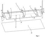
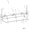
- a gripping device 1 comprises a frame 2 comprising two vertical uprights 2a connected by a horizontal beam 2b.
- the frame 2 comprises three pairs of grippers 3. Each pair of grippers 3 comprises a gripper 3 positioned on each side of the beam 2a so as to balance the assembly.
- the grippers 3 are grippers by adhesion and they therefore have the ability to adhere to a flat surface by the action of a control means 11.
- Such grippers may be constituted for example by electromagnets whose magnetic adhesion is controlled by the passage of an electric current in a coil of the gripper.
- the grippers 3 may consist of suction cups, the adhesion of which is controlled by a pneumatic depression.
- the frame 2 comprises, in the vicinity of each of the lower ends of the uprights 2a, a clamp 4 which is controllable in opening and closing.
- the grippers 3 and the clamps 4 are movable relative to each other by the ends of the beam 2b sliding along the uprights 2a.
- the vertical movement of the beam 2b is ensured on the one hand by a conventional lifting means, and not shown, of the hoist type for example, capable of lifting the whole of the frame 1 or by a vertical mobility means M located at each end of the beam 2b and comprising, for example, a motorized nut M intended to rotate around a screw that the associated upright 2a comprises so as to make raise or lower the beam 2 along the amount 2a.
- the grippers 4 have hydraulically activated jaws 4 sized to be able to hold a plate 10 weighing several hundred kilos in a pinch.
- the length of the beam 2b can vary thanks to sleeves 5 of the beam 2b in which the bars 6 of the beam 2b can slide and this by simple spacing or bringing together of the uprights 2a of the chassis 2.
- the adjustment of the length of the beam 2b can be done manually by moving the uprights 2a apart or bringing them closer to each other then by blocking the sliding of the bars 2b relative to the sleeves 5 by pins for example (pins not shown) in the case where a long series of plates of the same size must be handled.
- clamps 4 can each pivot around a substantially horizontal pivot axis 4a.
- the pivot axes 4a of each gripper are co-linear and a pivot motor P allows rotational drive of at least one gripper 4 around the pivot axle 4a.
- the clamps 4 also include a translation motor means T of the clamps 4 collinearly with the pivot axis 4a.
- the device 1 is located above a work surface 20 on which rests a plate 10 to be grasped.
- the spacing between the uprights 2a of the frame 2 is chosen by the person skilled in the art so that it is adapted to the dimension of the plate 10 to be gripped by sliding the bars 6 in the sleeves 5 of the beam 2b .
- the frame 2 is lowered vertically by the lifting means until the grippers 3 are in contact with a first face 10a of the plate 10, first face 10a which is exposed upwards.
- the adhesion of the grippers 3 with the plate 10 is caused by the action on the control means 11.
- the frame 2 is raised by the lifting means to a height H of the work surface 20 (H is the distance between the axis 4a of the grippers and the work surface 20) and the grippers 3 are raised thanks to the motor means M relative to the clamps 4 so that opposite edges of the plate 10 are at the same vertical level as the clamps 4. It can be seen that thanks to the invention the plate 10 can be lifted without it being necessary to have access to its peripheral edges. This is very useful when the plate has dimensions smaller than those of the worktop.
- the clamps 4 are brought closer to the edges of the plate 10 thanks to the translation means T then clamp the opposite edges of the plate 10. It is noted in the present case that the pivot axes 4a of the clamps 4 are coplanar with the plate 10. The plate 10 being lifted from the work surface 20, we have access to its peripheral edges and the clamps 4 will be able to grasp the plate at this level, which was not possible when the plate was placed on the work surface. 20.
- the grippers 3 are controlled so as to interrupt their adhesion with the plate 10.
- the beam 2b is raised along the uprights 2a at a distance D from the plate 10 thanks to the vertical mobility means M.
- the distance D is chosen such that the plate 10 can subsequently pivot without interfering with the grippers 3.
- the height H between the pivot axis 4a of the grippers and the work surface 20 is also chosen as that plate 10 can subsequently pivot without interfering with worktop 20.
- the plate 10 is pivoted around the pivot axes 4a of the grippers 4.
- the distance D between the pivot axis 4a and the beam 2b carrying the grippers 3 and the height H separating these same pivot axes 4a from the work plane 20 are such that the plate 10 can rotate without interfering with the grippers 3 or with the work plan 20.
- the vertical position could possibly be used to move the plate vertically and store it in a suitable support.
- a blocking means (not shown) of the plate in the vertical position will then be provided.
- the reversal of the plate 10 is then partial.
- the plate 10 has been rotated 180 degrees (complete reversal), relative to its initial angular position shown in figures 1 to 3 , so as to expose a second face 10b exposed upwards to allow machining or assembly.
- the plate 10 has its first face 10a facing the work surface 20.
- the grippers 3 are lowered using the vertical mobility means M and brought back into contact with the plate 10, then adhesion is activated.
- the plate 10 thus maintained, the clamps 4 can be loosened and moved away from the plate 10 thanks to the translation means T.
- FIG 10 The frame 2 is lowered vertically by means of the lifting means until the plate 10 rests on the work surface 20 by its first face 10a, which allows the adhesion of the grippers 3 to be stopped.
- the frame 2 is then moved away of the work surface 20 thanks to the lifting means thus leaving the plate 10 turned over, placed on its first face 10a, thus leaving free access to the second face 10b and this without passing through an intermediate workstation or the use of a specially arranged work surface.
Landscapes
- Engineering & Computer Science (AREA)
- Mechanical Engineering (AREA)
- Physics & Mathematics (AREA)
- Electromagnetism (AREA)
- Conveying And Assembling Of Building Elements In Situ (AREA)
- Manipulator (AREA)
- Load-Engaging Elements For Cranes (AREA)
- Laminated Bodies (AREA)
Claims (9)
- - Vorrichtung (1) zur Handhabung eines starren Panels wie eine Platte (10), wobei die Vorrichtung ein Traggestell (2) aufweist, wobei das Gestell (2) imstande ist, sich zu bewegen und mindestens einen Haftgreifer (3) aufweist, der bestimmt ist, auf Befehl an einer ersten, nach oben zeigenden Fläche (10a) der Platte (10) zu haften, wobei das Gestell (2) mindestens eine Zange (4) aufweist, die an einem der Enden des Gestells (2) angeordnet und bestimmt ist, einen Rand der Platte (10) einzuklemmen, dadurch gekennzeichnet, dass die Zange (4) imstande ist, über mindestens 180 Grad um eine etwa horizontale Wendeachse (4a) mittels einer Motorisierung (P) derart zu schwenken, dass die Platte (10) teilweise oder vollständig derart umgedreht wird, dass eine zweite Fläche (10b) nach oben gerichtet ist.
- - Vorrichtung (1) nach Anspruch 1, dadurch gekennzeichnet, dass sie zwei Zangen (4) mit deren koaxialen Wendeachsen (4a) aufweist.
- - Vorrichtung (1) nach einem der Ansprüche 1 bis 2, dadurch gekennzeichnet, dass sie mindestens drei Haftgreifer (3) aufweist, die mit dem Gestell (2) fest verbunden und derart verteilt sind, dass die Platte (10) im Verhältnis zum Gestell (2) ausbalanciert gehalten wird.
- - Vorrichtung (1) nach einem der Ansprüche 1 bis 3, dadurch gekennzeichnet, dass die Haftgreifer (3) Elektromagnete (3) aufweisen.
- - Vorrichtung (1) nach einem der Ansprüche 1 bis 3, dadurch gekennzeichnet, dass die Haftgreifer (3) Saugnäpfe (3) aufweisen.
- - Vorrichtung (1) nach einem der Ansprüche 1 bis 5, dadurch gekennzeichnet, dass das Gestell (2) mindestens einen horizontalen Balken (2b) aufweist, an dem die Haftgreifer (3) befestigt sind, wobei der Balken (2b) im Verhältnis zu vertikalen Stützen (2a) derart beweglich ist, dass die Platte (10) gehandhabt werden kann.
- - Vorrichtung (1) nach einem der Ansprüche 1 bis 6, dadurch gekennzeichnet, dass die Zangen (4) mit den vertikalen Stützen (2a) fest verbunden und zu diesen derart beweglich sind, dass sie den Rändern der Platte (10) zugewandt platzierbar sind, sobald die Greifer (3) die Platte (10) erfasst haben.
- - Verfahren zur Handhabung eines starren Panels wie eine Platte (10), die auf einer Arbeitsfläche (20) angeordnet ist und eine Vorrichtung zur Handhabung (1) nach einem der Ansprüche 1 bis 7 verwendet, dadurch gekennzeichnet, dass:- das Gestell (2) zur Platte (10) abgesenkt wird, bis die Haftgreifer (3) mit der Platte (10) in Kontakt treten;- den Haftgreifern (3) befohlen wird, an der Platte (10) zu haften;- die Platte (10) anhand einer Aufwärtsbewegung des Gestells (2) angehoben wird;- die Zangen (4) in die Nähe der Ränder der Platte (10) geführt werden;- das Spannen der Platte (10) durch die Zangen (4) im Bereich gegenüberliegender Ränder befohlen wird;- die Haftgreifer (3) freigegeben und von der Platte (10) beabstandet platziert werden;- die Zangen (4) um mindestens 90° im Verhältnis zum Gestell (2) geschwenkt werden.
- - Verfahren zur Handhabung einer Platte (10), die auf einer Arbeitsfläche nach Anspruch 8 angeordnet ist, dadurch gekennzeichnet, dass:- die Zangen (4) um 180° im Verhältnis zum Gestell (2) geschwenkt werden;- die Haftgreifer (3) in Kontakt mit der Platte (10) geführt werden und ihnen befohlen wird, an dieser zu haften;- die Zangen (4) gelöst und von der Platte (10) beabstandet werden;- das Gestell (2) abgesenkt wird, bis die Platte (10) auf der Arbeitsfläche (20) ruht;- die Haftgreifer (3) freigegeben werden und das Gestell (2) von der Arbeitsfläche (20) entfernt wird.
Applications Claiming Priority (1)
| Application Number | Priority Date | Filing Date | Title |
|---|---|---|---|
| FR1906072A FR3097213B1 (fr) | 2019-06-11 | 2019-06-11 | Dispositif de manutention d'un panneau rigide et procédé de manutention utilisant un tel dispositif |
Publications (2)
| Publication Number | Publication Date |
|---|---|
| EP3750841A1 EP3750841A1 (de) | 2020-12-16 |
| EP3750841B1 true EP3750841B1 (de) | 2022-03-02 |
Family
ID=68343008
Family Applications (1)
| Application Number | Title | Priority Date | Filing Date |
|---|---|---|---|
| EP20177123.5A Active EP3750841B1 (de) | 2019-06-11 | 2020-05-28 | Vorrichtung zur handhabung eines starren panels und handhabungsverfahren mit solchen vorrichtung |
Country Status (3)
| Country | Link |
|---|---|
| EP (1) | EP3750841B1 (de) |
| ES (1) | ES2913177T3 (de) |
| FR (1) | FR3097213B1 (de) |
Cited By (1)
| Publication number | Priority date | Publication date | Assignee | Title |
|---|---|---|---|---|
| IT202300019185A1 (it) * | 2023-09-19 | 2025-03-19 | Gruppo Tecnoferrari Spa | Macchina e metodo per ribaltare una lastra |
Families Citing this family (2)
| Publication number | Priority date | Publication date | Assignee | Title |
|---|---|---|---|---|
| CN116495603B (zh) * | 2023-06-30 | 2023-08-29 | 山东三箭建设工程股份有限公司 | 一种可调节的工字钢梁起吊器 |
| EP4563336A1 (de) * | 2023-12-01 | 2025-06-04 | Siemens Gamesa Renewable Energy A/S | Transportvorrichtung |
Family Cites Families (4)
| Publication number | Priority date | Publication date | Assignee | Title |
|---|---|---|---|---|
| BE795685A (fr) * | 1972-03-01 | 1973-06-18 | Siempelkamp Gmbh & Co | Dispositif de manipulation de feuilles de placage |
| JPS5629308Y2 (de) * | 1977-09-29 | 1981-07-13 | ||
| DE19911897B4 (de) * | 1999-03-17 | 2008-02-21 | Woko Gmbh | Lasthebemagnet |
| FR3047984A1 (fr) | 2016-02-22 | 2017-08-25 | Entrepose Group | Outil pour le retournement et la manutention de toles |
-
2019
- 2019-06-11 FR FR1906072A patent/FR3097213B1/fr active Active
-
2020
- 2020-05-28 ES ES20177123T patent/ES2913177T3/es active Active
- 2020-05-28 EP EP20177123.5A patent/EP3750841B1/de active Active
Cited By (1)
| Publication number | Priority date | Publication date | Assignee | Title |
|---|---|---|---|---|
| IT202300019185A1 (it) * | 2023-09-19 | 2025-03-19 | Gruppo Tecnoferrari Spa | Macchina e metodo per ribaltare una lastra |
Also Published As
| Publication number | Publication date |
|---|---|
| ES2913177T3 (es) | 2022-05-31 |
| FR3097213A1 (fr) | 2020-12-18 |
| FR3097213B1 (fr) | 2021-05-21 |
| EP3750841A1 (de) | 2020-12-16 |
Similar Documents
| Publication | Publication Date | Title |
|---|---|---|
| EP4234457B1 (de) | Palettengreifer | |
| EP0069661B1 (de) | Automatische Blechbiegemaschine | |
| EP3750841A1 (de) | Vorrichtung zur handhabung eines starren panels und handhabungsverfahren mit solchen vorrichtung | |
| EP3647208B1 (de) | Transportwagen | |
| FR2652529A1 (fr) | Robot. | |
| FR2982188A1 (fr) | Dispositif elliptique manipulateur de palier | |
| FR2563757A1 (fr) | Cisaille a guillotine | |
| FR2695586A1 (fr) | Dispositif et appareil de soudage. | |
| EP3150544B1 (de) | Greifvorrichtung für granate, und entsprechende trage | |
| FR2556489A1 (fr) | Appareil pour abattre des barres de poison combustible afin de les stocker dans un volume reduit | |
| FR2736626A1 (fr) | Appareil de manutention destine a manipuler des articles en forme de panneaux | |
| CA2577170C (fr) | Poste de realisation d'un travail sur une piece | |
| FR2729376A1 (fr) | Dispositif distributeur de barquettes | |
| EP0188987B1 (de) | Palettiervorrichtung, insbesondere für Säcke | |
| EP0252936B1 (de) | Vorrichtung zum abheben von bogenpaketen, insbesondere von papier, von stapeln | |
| FR2575735A1 (fr) | Dispositif d'empilage de flans | |
| EP3162741B1 (de) | Extraktionsmethode | |
| WO2008068249A1 (fr) | Prehenseur de pieces de tolerie de taille et/ou de types differents | |
| FR2514738A1 (fr) | Dispositif de prehension et de manipulation de casiers, et casier associe | |
| FR2972951A1 (fr) | Systeme de chargement-dechargement de grandes palettes porte-piece pour machine-outil | |
| FR3148925A1 (fr) | Préhenseur à palpeur pour dispositif de palettisation, et dispositif de palettisation le comprenant | |
| EP2097210B1 (de) | Verfahren und system zur positionierung eines teil auf einem montage- und produktionslinie | |
| EP3208042A1 (de) | Werkzeug zum wenden und fördern von blechen | |
| FR2942157A1 (fr) | Dispositif de manutention concu pour une ligne d'emboutissage | |
| FR2795012A1 (fr) | Dispositif de transfert de pieces a usiner |
Legal Events
| Date | Code | Title | Description |
|---|---|---|---|
| PUAI | Public reference made under article 153(3) epc to a published international application that has entered the european phase |
Free format text: ORIGINAL CODE: 0009012 |
|
| STAA | Information on the status of an ep patent application or granted ep patent |
Free format text: STATUS: THE APPLICATION HAS BEEN PUBLISHED |
|
| AK | Designated contracting states |
Kind code of ref document: A1 Designated state(s): AL AT BE BG CH CY CZ DE DK EE ES FI FR GB GR HR HU IE IS IT LI LT LU LV MC MK MT NL NO PL PT RO RS SE SI SK SM TR |
|
| AX | Request for extension of the european patent |
Extension state: BA ME |
|
| RAP1 | Party data changed (applicant data changed or rights of an application transferred) |
Owner name: NEXTER SYSTEMS |
|
| STAA | Information on the status of an ep patent application or granted ep patent |
Free format text: STATUS: REQUEST FOR EXAMINATION WAS MADE |
|
| 17P | Request for examination filed |
Effective date: 20210526 |
|
| RBV | Designated contracting states (corrected) |
Designated state(s): AL AT BE BG CH CY CZ DE DK EE ES FI FR GB GR HR HU IE IS IT LI LT LU LV MC MK MT NL NO PL PT RO RS SE SI SK SM TR |
|
| GRAP | Despatch of communication of intention to grant a patent |
Free format text: ORIGINAL CODE: EPIDOSNIGR1 |
|
| STAA | Information on the status of an ep patent application or granted ep patent |
Free format text: STATUS: GRANT OF PATENT IS INTENDED |
|
| RIC1 | Information provided on ipc code assigned before grant |
Ipc: B65H 15/00 20060101ALI20210920BHEP Ipc: B65H 5/10 20060101ALI20210920BHEP Ipc: B66C 1/06 20060101ALI20210920BHEP Ipc: B66C 1/02 20060101AFI20210920BHEP |
|
| INTG | Intention to grant announced |
Effective date: 20211019 |
|
| GRAS | Grant fee paid |
Free format text: ORIGINAL CODE: EPIDOSNIGR3 |
|
| GRAA | (expected) grant |
Free format text: ORIGINAL CODE: 0009210 |
|
| STAA | Information on the status of an ep patent application or granted ep patent |
Free format text: STATUS: THE PATENT HAS BEEN GRANTED |
|
| AK | Designated contracting states |
Kind code of ref document: B1 Designated state(s): AL AT BE BG CH CY CZ DE DK EE ES FI FR GB GR HR HU IE IS IT LI LT LU LV MC MK MT NL NO PL PT RO RS SE SI SK SM TR |
|
| REG | Reference to a national code |
Ref country code: GB Ref legal event code: FG4D Free format text: NOT ENGLISH |
|
| REG | Reference to a national code |
Ref country code: CH Ref legal event code: EP Ref country code: AT Ref legal event code: REF Ref document number: 1472120 Country of ref document: AT Kind code of ref document: T Effective date: 20220315 |
|
| REG | Reference to a national code |
Ref country code: DE Ref legal event code: R096 Ref document number: 602020002027 Country of ref document: DE |
|
| REG | Reference to a national code |
Ref country code: IE Ref legal event code: FG4D Free format text: LANGUAGE OF EP DOCUMENT: FRENCH |
|
| REG | Reference to a national code |
Ref country code: FI Ref legal event code: FGE |
|
| REG | Reference to a national code |
Ref country code: ES Ref legal event code: FG2A Ref document number: 2913177 Country of ref document: ES Kind code of ref document: T3 Effective date: 20220531 |
|
| REG | Reference to a national code |
Ref country code: NL Ref legal event code: FP |
|
| REG | Reference to a national code |
Ref country code: SE Ref legal event code: TRGR |
|
| REG | Reference to a national code |
Ref country code: LT Ref legal event code: MG9D |
|
| PG25 | Lapsed in a contracting state [announced via postgrant information from national office to epo] |
Ref country code: RS Free format text: LAPSE BECAUSE OF FAILURE TO SUBMIT A TRANSLATION OF THE DESCRIPTION OR TO PAY THE FEE WITHIN THE PRESCRIBED TIME-LIMIT Effective date: 20220302 Ref country code: NO Free format text: LAPSE BECAUSE OF FAILURE TO SUBMIT A TRANSLATION OF THE DESCRIPTION OR TO PAY THE FEE WITHIN THE PRESCRIBED TIME-LIMIT Effective date: 20220602 Ref country code: LT Free format text: LAPSE BECAUSE OF FAILURE TO SUBMIT A TRANSLATION OF THE DESCRIPTION OR TO PAY THE FEE WITHIN THE PRESCRIBED TIME-LIMIT Effective date: 20220302 Ref country code: HR Free format text: LAPSE BECAUSE OF FAILURE TO SUBMIT A TRANSLATION OF THE DESCRIPTION OR TO PAY THE FEE WITHIN THE PRESCRIBED TIME-LIMIT Effective date: 20220302 Ref country code: BG Free format text: LAPSE BECAUSE OF FAILURE TO SUBMIT A TRANSLATION OF THE DESCRIPTION OR TO PAY THE FEE WITHIN THE PRESCRIBED TIME-LIMIT Effective date: 20220602 |
|
| REG | Reference to a national code |
Ref country code: AT Ref legal event code: MK05 Ref document number: 1472120 Country of ref document: AT Kind code of ref document: T Effective date: 20220302 |
|
| PG25 | Lapsed in a contracting state [announced via postgrant information from national office to epo] |
Ref country code: PL Free format text: LAPSE BECAUSE OF FAILURE TO SUBMIT A TRANSLATION OF THE DESCRIPTION OR TO PAY THE FEE WITHIN THE PRESCRIBED TIME-LIMIT Effective date: 20220302 Ref country code: LV Free format text: LAPSE BECAUSE OF FAILURE TO SUBMIT A TRANSLATION OF THE DESCRIPTION OR TO PAY THE FEE WITHIN THE PRESCRIBED TIME-LIMIT Effective date: 20220302 Ref country code: GR Free format text: LAPSE BECAUSE OF FAILURE TO SUBMIT A TRANSLATION OF THE DESCRIPTION OR TO PAY THE FEE WITHIN THE PRESCRIBED TIME-LIMIT Effective date: 20220603 |
|
| PG25 | Lapsed in a contracting state [announced via postgrant information from national office to epo] |
Ref country code: SM Free format text: LAPSE BECAUSE OF FAILURE TO SUBMIT A TRANSLATION OF THE DESCRIPTION OR TO PAY THE FEE WITHIN THE PRESCRIBED TIME-LIMIT Effective date: 20220302 Ref country code: SK Free format text: LAPSE BECAUSE OF FAILURE TO SUBMIT A TRANSLATION OF THE DESCRIPTION OR TO PAY THE FEE WITHIN THE PRESCRIBED TIME-LIMIT Effective date: 20220302 Ref country code: RO Free format text: LAPSE BECAUSE OF FAILURE TO SUBMIT A TRANSLATION OF THE DESCRIPTION OR TO PAY THE FEE WITHIN THE PRESCRIBED TIME-LIMIT Effective date: 20220302 Ref country code: PT Free format text: LAPSE BECAUSE OF FAILURE TO SUBMIT A TRANSLATION OF THE DESCRIPTION OR TO PAY THE FEE WITHIN THE PRESCRIBED TIME-LIMIT Effective date: 20220704 Ref country code: EE Free format text: LAPSE BECAUSE OF FAILURE TO SUBMIT A TRANSLATION OF THE DESCRIPTION OR TO PAY THE FEE WITHIN THE PRESCRIBED TIME-LIMIT Effective date: 20220302 Ref country code: AT Free format text: LAPSE BECAUSE OF FAILURE TO SUBMIT A TRANSLATION OF THE DESCRIPTION OR TO PAY THE FEE WITHIN THE PRESCRIBED TIME-LIMIT Effective date: 20220302 |
|
| PG25 | Lapsed in a contracting state [announced via postgrant information from national office to epo] |
Ref country code: IS Free format text: LAPSE BECAUSE OF FAILURE TO SUBMIT A TRANSLATION OF THE DESCRIPTION OR TO PAY THE FEE WITHIN THE PRESCRIBED TIME-LIMIT Effective date: 20220702 Ref country code: AL Free format text: LAPSE BECAUSE OF FAILURE TO SUBMIT A TRANSLATION OF THE DESCRIPTION OR TO PAY THE FEE WITHIN THE PRESCRIBED TIME-LIMIT Effective date: 20220302 |
|
| REG | Reference to a national code |
Ref country code: DE Ref legal event code: R097 Ref document number: 602020002027 Country of ref document: DE |
|
| PLBE | No opposition filed within time limit |
Free format text: ORIGINAL CODE: 0009261 |
|
| STAA | Information on the status of an ep patent application or granted ep patent |
Free format text: STATUS: NO OPPOSITION FILED WITHIN TIME LIMIT |
|
| PG25 | Lapsed in a contracting state [announced via postgrant information from national office to epo] |
Ref country code: MC Free format text: LAPSE BECAUSE OF FAILURE TO SUBMIT A TRANSLATION OF THE DESCRIPTION OR TO PAY THE FEE WITHIN THE PRESCRIBED TIME-LIMIT Effective date: 20220302 Ref country code: LU Free format text: LAPSE BECAUSE OF NON-PAYMENT OF DUE FEES Effective date: 20220528 Ref country code: DK Free format text: LAPSE BECAUSE OF FAILURE TO SUBMIT A TRANSLATION OF THE DESCRIPTION OR TO PAY THE FEE WITHIN THE PRESCRIBED TIME-LIMIT Effective date: 20220302 |
|
| 26N | No opposition filed |
Effective date: 20221205 |
|
| PG25 | Lapsed in a contracting state [announced via postgrant information from national office to epo] |
Ref country code: SI Free format text: LAPSE BECAUSE OF FAILURE TO SUBMIT A TRANSLATION OF THE DESCRIPTION OR TO PAY THE FEE WITHIN THE PRESCRIBED TIME-LIMIT Effective date: 20220302 |
|
| PG25 | Lapsed in a contracting state [announced via postgrant information from national office to epo] |
Ref country code: IE Free format text: LAPSE BECAUSE OF NON-PAYMENT OF DUE FEES Effective date: 20220528 |
|
| REG | Reference to a national code |
Ref country code: CH Ref legal event code: PL |
|
| PG25 | Lapsed in a contracting state [announced via postgrant information from national office to epo] |
Ref country code: LI Free format text: LAPSE BECAUSE OF NON-PAYMENT OF DUE FEES Effective date: 20230531 Ref country code: CH Free format text: LAPSE BECAUSE OF NON-PAYMENT OF DUE FEES Effective date: 20230531 |
|
| PG25 | Lapsed in a contracting state [announced via postgrant information from national office to epo] |
Ref country code: MK Free format text: LAPSE BECAUSE OF FAILURE TO SUBMIT A TRANSLATION OF THE DESCRIPTION OR TO PAY THE FEE WITHIN THE PRESCRIBED TIME-LIMIT Effective date: 20220302 Ref country code: CY Free format text: LAPSE BECAUSE OF FAILURE TO SUBMIT A TRANSLATION OF THE DESCRIPTION OR TO PAY THE FEE WITHIN THE PRESCRIBED TIME-LIMIT Effective date: 20220302 |
|
| PG25 | Lapsed in a contracting state [announced via postgrant information from national office to epo] |
Ref country code: HU Free format text: LAPSE BECAUSE OF FAILURE TO SUBMIT A TRANSLATION OF THE DESCRIPTION OR TO PAY THE FEE WITHIN THE PRESCRIBED TIME-LIMIT; INVALID AB INITIO Effective date: 20200528 |
|
| PG25 | Lapsed in a contracting state [announced via postgrant information from national office to epo] |
Ref country code: MT Free format text: LAPSE BECAUSE OF FAILURE TO SUBMIT A TRANSLATION OF THE DESCRIPTION OR TO PAY THE FEE WITHIN THE PRESCRIBED TIME-LIMIT Effective date: 20220302 |
|
| PGFP | Annual fee paid to national office [announced via postgrant information from national office to epo] |
Ref country code: NL Payment date: 20260421 Year of fee payment: 7 |
|
| PGFP | Annual fee paid to national office [announced via postgrant information from national office to epo] |
Ref country code: ES Payment date: 20260601 Year of fee payment: 7 |
|
| PGFP | Annual fee paid to national office [announced via postgrant information from national office to epo] |
Ref country code: GB Payment date: 20260421 Year of fee payment: 7 |
|
| PGFP | Annual fee paid to national office [announced via postgrant information from national office to epo] |
Ref country code: IT Payment date: 20260421 Year of fee payment: 7 |
|
| PGFP | Annual fee paid to national office [announced via postgrant information from national office to epo] |
Ref country code: DE Payment date: 20260421 Year of fee payment: 7 |
|
| PGFP | Annual fee paid to national office [announced via postgrant information from national office to epo] |
Ref country code: FI Payment date: 20260421 Year of fee payment: 7 Ref country code: SE Payment date: 20260421 Year of fee payment: 7 |
|
| PGFP | Annual fee paid to national office [announced via postgrant information from national office to epo] |
Ref country code: BE Payment date: 20260421 Year of fee payment: 7 |
|
| PGFP | Annual fee paid to national office [announced via postgrant information from national office to epo] |
Ref country code: CZ Payment date: 20260504 Year of fee payment: 7 Ref country code: TR Payment date: 20260428 Year of fee payment: 7 |
|
| PGFP | Annual fee paid to national office [announced via postgrant information from national office to epo] |
Ref country code: FR Payment date: 20260422 Year of fee payment: 7 |