EP3750975A1 - Gasreiniger - Google Patents
Gasreiniger Download PDFInfo
- Publication number
- EP3750975A1 EP3750975A1 EP19768335.2A EP19768335A EP3750975A1 EP 3750975 A1 EP3750975 A1 EP 3750975A1 EP 19768335 A EP19768335 A EP 19768335A EP 3750975 A1 EP3750975 A1 EP 3750975A1
- Authority
- EP
- European Patent Office
- Prior art keywords
- converter
- temperature
- gas
- reaction
- heat exchanger
- Prior art date
- Legal status (The legal status is an assumption and is not a legal conclusion. Google has not performed a legal analysis and makes no representation as to the accuracy of the status listed.)
- Withdrawn
Links
Images

Classifications
-
- C—CHEMISTRY; METALLURGY
- C10—PETROLEUM, GAS OR COKE INDUSTRIES; TECHNICAL GASES CONTAINING CARBON MONOXIDE; FUELS; LUBRICANTS; PEAT
- C10K—PURIFYING OR MODIFYING THE CHEMICAL COMPOSITION OF COMBUSTIBLE GASES CONTAINING CARBON MONOXIDE
- C10K1/00—Purifying combustible gases containing carbon monoxide
- C10K1/002—Removal of contaminants
- C10K1/003—Removal of contaminants of acid contaminants, e.g. acid gas removal
- C10K1/006—Hydrogen cyanide
-
- B—PERFORMING OPERATIONS; TRANSPORTING
- B01—PHYSICAL OR CHEMICAL PROCESSES OR APPARATUS IN GENERAL
- B01D—SEPARATION
- B01D53/00—Separation of gases or vapours; Recovering vapours of volatile solvents from gases; Chemical or biological purification of waste gases, e.g. engine exhaust gases, smoke, fumes, flue gases, aerosols
- B01D53/34—Chemical or biological purification of waste gases
- B01D53/46—Removing components of defined structure
- B01D53/48—Sulfur compounds
- B01D53/52—Hydrogen sulfide
-
- B—PERFORMING OPERATIONS; TRANSPORTING
- B01—PHYSICAL OR CHEMICAL PROCESSES OR APPARATUS IN GENERAL
- B01D—SEPARATION
- B01D53/00—Separation of gases or vapours; Recovering vapours of volatile solvents from gases; Chemical or biological purification of waste gases, e.g. engine exhaust gases, smoke, fumes, flue gases, aerosols
- B01D53/34—Chemical or biological purification of waste gases
- B01D53/74—General processes for purification of waste gases; Apparatus or devices specially adapted therefor
- B01D53/86—Catalytic processes
- B01D53/8603—Removing sulfur compounds
- B01D53/8606—Removing sulfur compounds only one sulfur compound other than sulfur oxides or hydrogen sulfide
-
- B—PERFORMING OPERATIONS; TRANSPORTING
- B01—PHYSICAL OR CHEMICAL PROCESSES OR APPARATUS IN GENERAL
- B01D—SEPARATION
- B01D53/00—Separation of gases or vapours; Recovering vapours of volatile solvents from gases; Chemical or biological purification of waste gases, e.g. engine exhaust gases, smoke, fumes, flue gases, aerosols
- B01D53/34—Chemical or biological purification of waste gases
- B01D53/74—General processes for purification of waste gases; Apparatus or devices specially adapted therefor
- B01D53/86—Catalytic processes
- B01D53/8621—Removing nitrogen compounds
-
- B—PERFORMING OPERATIONS; TRANSPORTING
- B01—PHYSICAL OR CHEMICAL PROCESSES OR APPARATUS IN GENERAL
- B01J—CHEMICAL OR PHYSICAL PROCESSES, e.g. CATALYSIS OR COLLOID CHEMISTRY; THEIR RELEVANT APPARATUS
- B01J19/00—Chemical, physical or physico-chemical processes in general; Their relevant apparatus
- B01J19/0006—Controlling or regulating processes
- B01J19/0013—Controlling the temperature of the process
-
- C—CHEMISTRY; METALLURGY
- C10—PETROLEUM, GAS OR COKE INDUSTRIES; TECHNICAL GASES CONTAINING CARBON MONOXIDE; FUELS; LUBRICANTS; PEAT
- C10K—PURIFYING OR MODIFYING THE CHEMICAL COMPOSITION OF COMBUSTIBLE GASES CONTAINING CARBON MONOXIDE
- C10K1/00—Purifying combustible gases containing carbon monoxide
- C10K1/002—Removal of contaminants
- C10K1/003—Removal of contaminants of acid contaminants, e.g. acid gas removal
- C10K1/004—Sulfur containing contaminants, e.g. hydrogen sulfide
-
- C—CHEMISTRY; METALLURGY
- C10—PETROLEUM, GAS OR COKE INDUSTRIES; TECHNICAL GASES CONTAINING CARBON MONOXIDE; FUELS; LUBRICANTS; PEAT
- C10K—PURIFYING OR MODIFYING THE CHEMICAL COMPOSITION OF COMBUSTIBLE GASES CONTAINING CARBON MONOXIDE
- C10K1/00—Purifying combustible gases containing carbon monoxide
- C10K1/08—Purifying combustible gases containing carbon monoxide by washing with liquids; Reviving the used wash liquors
- C10K1/10—Purifying combustible gases containing carbon monoxide by washing with liquids; Reviving the used wash liquors with aqueous liquids
- C10K1/101—Purifying combustible gases containing carbon monoxide by washing with liquids; Reviving the used wash liquors with aqueous liquids with water only
-
- C—CHEMISTRY; METALLURGY
- C10—PETROLEUM, GAS OR COKE INDUSTRIES; TECHNICAL GASES CONTAINING CARBON MONOXIDE; FUELS; LUBRICANTS; PEAT
- C10K—PURIFYING OR MODIFYING THE CHEMICAL COMPOSITION OF COMBUSTIBLE GASES CONTAINING CARBON MONOXIDE
- C10K1/00—Purifying combustible gases containing carbon monoxide
- C10K1/34—Purifying combustible gases containing carbon monoxide by catalytic conversion of impurities to more readily removable materials
-
- B—PERFORMING OPERATIONS; TRANSPORTING
- B01—PHYSICAL OR CHEMICAL PROCESSES OR APPARATUS IN GENERAL
- B01D—SEPARATION
- B01D2251/00—Reactants
-
- B—PERFORMING OPERATIONS; TRANSPORTING
- B01—PHYSICAL OR CHEMICAL PROCESSES OR APPARATUS IN GENERAL
- B01D—SEPARATION
- B01D2252/00—Absorbents, i.e. solvents and liquid materials for gas absorption
- B01D2252/10—Inorganic absorbents
- B01D2252/103—Water
-
- B—PERFORMING OPERATIONS; TRANSPORTING
- B01—PHYSICAL OR CHEMICAL PROCESSES OR APPARATUS IN GENERAL
- B01D—SEPARATION
- B01D2255/00—Catalysts
- B01D2255/10—Noble metals or compounds thereof
- B01D2255/102—Platinum group metals
- B01D2255/1026—Ruthenium
-
- B—PERFORMING OPERATIONS; TRANSPORTING
- B01—PHYSICAL OR CHEMICAL PROCESSES OR APPARATUS IN GENERAL
- B01D—SEPARATION
- B01D2255/00—Catalysts
- B01D2255/20—Metals or compounds thereof
- B01D2255/204—Alkaline earth metals
- B01D2255/2042—Barium
-
- B—PERFORMING OPERATIONS; TRANSPORTING
- B01—PHYSICAL OR CHEMICAL PROCESSES OR APPARATUS IN GENERAL
- B01D—SEPARATION
- B01D2255/00—Catalysts
- B01D2255/20—Metals or compounds thereof
- B01D2255/207—Transition metals
- B01D2255/20707—Titanium
-
- B—PERFORMING OPERATIONS; TRANSPORTING
- B01—PHYSICAL OR CHEMICAL PROCESSES OR APPARATUS IN GENERAL
- B01D—SEPARATION
- B01D2255/00—Catalysts
- B01D2255/20—Metals or compounds thereof
- B01D2255/207—Transition metals
- B01D2255/20715—Zirconium
-
- B—PERFORMING OPERATIONS; TRANSPORTING
- B01—PHYSICAL OR CHEMICAL PROCESSES OR APPARATUS IN GENERAL
- B01D—SEPARATION
- B01D2255/00—Catalysts
- B01D2255/20—Metals or compounds thereof
- B01D2255/207—Transition metals
- B01D2255/20746—Cobalt
-
- B—PERFORMING OPERATIONS; TRANSPORTING
- B01—PHYSICAL OR CHEMICAL PROCESSES OR APPARATUS IN GENERAL
- B01D—SEPARATION
- B01D2255/00—Catalysts
- B01D2255/20—Metals or compounds thereof
- B01D2255/207—Transition metals
- B01D2255/20753—Nickel
-
- B—PERFORMING OPERATIONS; TRANSPORTING
- B01—PHYSICAL OR CHEMICAL PROCESSES OR APPARATUS IN GENERAL
- B01D—SEPARATION
- B01D2255/00—Catalysts
- B01D2255/20—Metals or compounds thereof
- B01D2255/207—Transition metals
- B01D2255/20769—Molybdenum
-
- B—PERFORMING OPERATIONS; TRANSPORTING
- B01—PHYSICAL OR CHEMICAL PROCESSES OR APPARATUS IN GENERAL
- B01D—SEPARATION
- B01D2255/00—Catalysts
- B01D2255/40—Mixed oxides
-
- B—PERFORMING OPERATIONS; TRANSPORTING
- B01—PHYSICAL OR CHEMICAL PROCESSES OR APPARATUS IN GENERAL
- B01D—SEPARATION
- B01D2257/00—Components to be removed
- B01D2257/30—Sulfur compounds
- B01D2257/304—Hydrogen sulfide
-
- B—PERFORMING OPERATIONS; TRANSPORTING
- B01—PHYSICAL OR CHEMICAL PROCESSES OR APPARATUS IN GENERAL
- B01D—SEPARATION
- B01D2257/00—Components to be removed
- B01D2257/30—Sulfur compounds
- B01D2257/308—Carbonoxysulfide COS
-
- B—PERFORMING OPERATIONS; TRANSPORTING
- B01—PHYSICAL OR CHEMICAL PROCESSES OR APPARATUS IN GENERAL
- B01D—SEPARATION
- B01D2257/00—Components to be removed
- B01D2257/40—Nitrogen compounds
- B01D2257/408—Cyanides, e.g. hydrogen cyanide (HCH)
-
- B—PERFORMING OPERATIONS; TRANSPORTING
- B01—PHYSICAL OR CHEMICAL PROCESSES OR APPARATUS IN GENERAL
- B01D—SEPARATION
- B01D2258/00—Sources of waste gases
- B01D2258/01—Engine exhaust gases
- B01D2258/012—Diesel engines and lean burn gasoline engines
-
- B—PERFORMING OPERATIONS; TRANSPORTING
- B01—PHYSICAL OR CHEMICAL PROCESSES OR APPARATUS IN GENERAL
- B01D—SEPARATION
- B01D53/00—Separation of gases or vapours; Recovering vapours of volatile solvents from gases; Chemical or biological purification of waste gases, e.g. engine exhaust gases, smoke, fumes, flue gases, aerosols
- B01D53/34—Chemical or biological purification of waste gases
- B01D53/74—General processes for purification of waste gases; Apparatus or devices specially adapted therefor
- B01D53/75—Multi-step processes
-
- B—PERFORMING OPERATIONS; TRANSPORTING
- B01—PHYSICAL OR CHEMICAL PROCESSES OR APPARATUS IN GENERAL
- B01J—CHEMICAL OR PHYSICAL PROCESSES, e.g. CATALYSIS OR COLLOID CHEMISTRY; THEIR RELEVANT APPARATUS
- B01J2219/00—Chemical, physical or physico-chemical processes in general; Their relevant apparatus
- B01J2219/00049—Controlling or regulating processes
- B01J2219/00051—Controlling the temperature
- B01J2219/00054—Controlling or regulating the heat exchange system
- B01J2219/00056—Controlling or regulating the heat exchange system involving measured parameters
- B01J2219/00058—Temperature measurement
-
- B—PERFORMING OPERATIONS; TRANSPORTING
- B01—PHYSICAL OR CHEMICAL PROCESSES OR APPARATUS IN GENERAL
- B01J—CHEMICAL OR PHYSICAL PROCESSES, e.g. CATALYSIS OR COLLOID CHEMISTRY; THEIR RELEVANT APPARATUS
- B01J2219/00—Chemical, physical or physico-chemical processes in general; Their relevant apparatus
- B01J2219/00049—Controlling or regulating processes
- B01J2219/00164—Controlling or regulating processes controlling the flow
Definitions
- the present disclosure relates to a gas purification device.
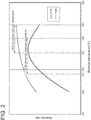
- the temperature of the syngas may be adjusted in a range of 280°C to 320°C which is an optimum temperature range common to the reactions (1) and (2).
- the concentration of either COS or HCN increases, and hydrolysis reaction of the component having the increased concentration needs to be accelerated, since the temperature of the syngas cannot be adjusted with the configuration of Patent Document 3, the component having the increased concentration cannot be preferentially hydrolyzed.
- a gas purification device comprises: a converter packed with a catalyst for hydrolyzing both COS and HCN; an upstream heat exchanger for heat exchange between a gas to be introduced into the converter and a cooling fluid for cooling the gas; a reaction-temperature estimation member for estimating a reaction temperature inside the converter; and a flow-rate adjustment member for adjusting a flow rate of the cooling fluid flowing into the upstream heat exchanger based on an estimated value of the reaction-temperature estimation member to control the reaction temperature.
- the reaction temperature in the converter can be controlled.
- the gas purification device may further comprise: an analysis device disposed upstream of the converter and configured to analyze a concentration of COS and a concentration of HCN in the gas; and a setting-temperature-range determination unit configured to determine a setting temperature range of the reaction temperature based on an analysis result of the analysis device.
- the flow-rate adjustment member may be configured to adjust the flow rate of the cooling fluid flowing into the upstream heat exchanger such that the estimated value of the reaction-temperature estimation member is within the setting temperature range.
- the gas to be introduced into the converter may be a syngas obtained by gasification of coal.
- the reaction temperature in the converter can be controlled.
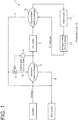
- the gas purification device 1 includes a converter 2 packed with a catalyst for hydrolyzing both COS and HCN, an upstream heat exchanger 3 for heat exchange between a syngas to be introduced into the converter 2 and a cooling fluid for cooling the syngas, a temperature sensor 4 disposed between the upstream heat exchanger 3 and the converter 2 to detect the temperature of the syngas flowing into the converter 2, and a flow-rate adjustment valve 5 which is a flow-rate adjustment member for adjusting the flow rate of the cooling fluid flowing into the upstream heat exchanger 3.
- the catalyst packed in the converter 2 is a catalyst for hydrolyzing both COS and HCN.
- the catalyst may be a catalyst in which an active component mainly containing at least one of barium, nickel, ruthenium, cobalt, or molybdenum is supported on a titanium oxide-based carrier.
- the titanium oxide-based carrier is at least one of a composite oxide of titanium oxide and silicon oxide, a composite oxide of titanium oxide and aluminum oxide, or a composite oxide of titanium oxide and zirconium oxide, and at least one of barium carbonate, nickel carbonate, ruthenium nitrate, cobalt carbonate, or ammonium molybdate is added to the titanium oxide-based carrier.
- the temperature sensor 4 constitutes a reaction-temperature estimation member for estimating the reaction temperature inside the converter 2.
- the cooling fluid used for heat exchange with the syngas in the upstream heat exchanger 3 may be any fluid that has a lower temperature than the syngas.
- a purified gas obtained by desulfurization of the syngas that has passed through the converter 2 is used as the cooling fluid.
- the gas purification device 1 further includes a purification unit 10 for purifying the syngas having passed through the converter 2 to produce a purified gas, and a downstream heat exchanger 6 for heat exchange between the syngas flowing out of the converter 2 and the purified gas.
- the purification unit 10 includes a wash tower 11 configured to bring the syngas and water into contact to cool the syngas, and a hydrogen-sulfide removal device 12 configured to remove H2S produced by hydrolysis of COS from the cooled syngas to produce a purified gas.
- a branch pipe 8 communicating with the upstream heat exchanger 3 diverges from a middle portion of a pipe 7 through which the purified gas that has exchanged heat with the syngas in the downstream heat exchanger 6 flows.
- the flow-rate adjustment valve 5 is disposed on the branch pipe 8.
- the pipe 7 is jointed to a pipe 9 through which the purified gas that has exchanged heat with the syngas in the upstream heat exchanger 3 flows.
- the pipe 9 communicates with a gas turbine of the integrated coal gasification combined cycle power plant.
- the syngas from the gasifier contains COS and HCN.
- concentrations of COS and HCN in the syngas are roughly determined by the type of coal fed to the gasifier. Therefore, concentrations of COS and HCN in the syngas that are assumed when standard coal is fed to the gasifier are defined as planned values of the concentrations of COS and HCN.
- the appropriate reaction rate of each component is determined based on each planned value, and the setting temperature range of the reaction temperature of the converter 2 is determined based on each reaction rate.
- the gas purification device 1 when the standard coal is fed to the gasifier, i.e., when the concentrations of COS and HCN in the syngas are the planned values, the gas purification device 1 is operated under conditions that accelerate both hydrolysis reactions of COS and HCN.
- the setting temperature range of the reaction temperature is set to a common temperature range (280 to 320°C) in which the COS conversion optimum temperature and the HCN conversion optimum temperature overlap (see FIG. 2 ).
- This setting temperature range is for illustrative purpose only, and the setting temperature range when the concentration of each component is the planned value may be determined in any way.
- the opening degree of the flow-rate adjustment valve 5 is decreased to decrease the flow rate of the purified gas flowing into the upstream heat exchanger 3.
- the expected concentrations of COS and HCN in the syngas may change. If the concentration of one of COS or HCN increases, it is necessary to change the setting temperature range of the reaction temperature so as to accelerate hydrolysis reaction of the component having the increased concentration.
- the setting temperature range is changed to, for example, 280 to 350°C in order to increase the reaction rate of hydrolysis reaction of HCN.
- the reaction rate of hydrolysis reaction of COS may be reduced to some extent as compared with the unchanged temperature range (280 to 320°C), but the reaction rate of hydrolysis reaction of HCN is preferentially increased in response to the increase in the concentration of HCN.
- the setting temperature range is changed to, for example, 240 to 320°C in order to increase the reaction rate of hydrolysis reaction of COS.
- the reaction rate of hydrolysis reaction of HCN may be reduced to some extent as compared with the unchanged temperature range, but the reaction rate of hydrolysis reaction of COS is preferentially increased in response to the increase in the concentration of COS.
- the flow rate of the purified gas flowing into the upstream heat exchanger 3 as the cooling fluid is changed by changing the opening degree of the flow-rate adjustment valve 5 in order to change the temperature of the syngas flowing into the converter 2.
- the reaction rate of hydrolysis reaction of either one of COS or HCN is changed in response to a concentration change of COS and HCN.
- the gas purification device according to the second embodiment differs from the first embodiment in that it is configured to analyze the concentrations of CON and HCN in the syngas flowing into the converter, and control the reaction temperature based on the analysis result.
- the same constituent elements as those in the first embodiment are associated with the same reference numerals and not described again in detail.
- the gas purification device 1 includes an analysis device 21 disposed between the gasifier and the upstream heat exchanger 3, and a setting-temperature-range determination unit 22 electrically connected to the analysis device 21 and to the temperature sensor 4.
- the analysis device 21 serves to analyze the concentrations of COS and HCN in the syngas.
- the setting-temperature-range determination unit 22 serves to determine the setting temperature range of the reaction temperature based on the analysis result of the analysis device 21, and is incorporated in, for example, a computer which controls the operation of the integrated coal gasification combined cycle power plant.
- the configuration is otherwise the same as that of the first embodiment.
- the second embodiment differs from the first embodiment in that, during operation of the gas purification device 1, the analysis device 21 measures the concentrations of COS and HCN in the syngas, and the setting-temperature-range determination unit 22 determines the setting temperature range based on the concentrations, to adjust the flow rate of the purified gas flowing into the upstream heat exchanger 3 such that the reaction temperature inside the converter 2 is within the setting temperature range.
- the analysis device 21 measures the concentrations of COS and HCN in the syngas
- the setting-temperature-range determination unit 22 determines the setting temperature range based on the concentrations, to adjust the flow rate of the purified gas flowing into the upstream heat exchanger 3 such that the reaction temperature inside the converter 2 is within the setting temperature range.
- the setting-temperature-range determination unit 22 changes the setting temperature range to, for example, 280 to 320°C in order to increase the reaction rate of hydrolysis reaction of HCN.
- the setting-temperature-range determination unit 22 changes the setting temperature range to, for example, 240 to 320°C in order to increase the reaction rate of hydrolysis reaction of COS.
- the setting temperature range may be finely determined so as to correspond to the concentration of each component. The operation of adjusting the flow rate of the purified gas flowing into the upstream heat exchanger 3 to control the reaction temperature within the changed setting temperature range is the same as that in the first embodiment.
- reaction temperature is controlled to be within the setting temperature range determined based on the analysis result of the COS concentration and the HCN concentration in the syngas, it is possible to more accurately change the reaction rate of hydrolysis reaction of each component in response to a concentration change of COS and HCN in the gas.
- the temperature sensor 4 is disposed upstream of the upstream heat exchanger 3, embodiments are not limited thereto.
- the concentrations of COS and HCN in the syngas are on the order of ppm, the amount of heat released during hydrolysis in the converter 2 is small, so the temperature of the syngas flowing into the converter 2 is substantially the same as the temperature of the syngas flowing out of the converter 2. Therefore, the temperature sensor 4 may be disposed downstream of the converter 2, i.e., between the converter 2 and the downstream heat exchanger 6. Depending on the configuration of the converter 2, the temperature sensor 4 may be disposed so as to detect the temperature inside the converter 2.
- the reaction-temperature estimation member is the temperature sensor 4, it is not limited thereto.
- the reaction-temperature estimation member may be a unit for calculating the temperature of the syngas flowing into the converter 2. For instance, when the temperature and flow rate of the syngas from the gasifier and the temperature and flow rate of the purified gas flowing into the upstream heat exchanger 3 are known, the temperature of the syngas flowing out of the upstream heat exchanger 3, i.e., the temperature of the syngas flowing into the converter 2 can be calculated.
- the cooling fluid used in the upstream heat exchanger 3 is the purified gas obtained by desulfurization of the syngas that has passed through the converter 2, but the cooling fluid is not limited to the purified gas.
- the cooling fluid may be any fluid that has a lower temperature than the syngas, for example, steam having a lower temperature than the syngas.
- a supply source having any configuration may be provided in the gas purification device 1.
- the steam supply source may be a steam turbine, and steam extracted from an outlet of a high-pressure turbine or an intermediate-pressure turbine of the steam turbine may be used as the cooling fluid. In this case, it is possible to reduce the gas purification cost compared with the case where the steam is separately prepared.
- the gas purification device 1 has been described as a part of the integrated coal gasification combined cycle power plant, but the embodiment is not limited thereto.
- the gas purification device 1 can be provided in any facility.
Landscapes
- Chemical & Material Sciences (AREA)
- Engineering & Computer Science (AREA)
- Combustion & Propulsion (AREA)
- Chemical Kinetics & Catalysis (AREA)
- General Chemical & Material Sciences (AREA)
- Oil, Petroleum & Natural Gas (AREA)
- Organic Chemistry (AREA)
- Health & Medical Sciences (AREA)
- Environmental & Geological Engineering (AREA)
- Analytical Chemistry (AREA)
- Biomedical Technology (AREA)
- Toxicology (AREA)
- Industrial Gases (AREA)
Applications Claiming Priority (2)
| Application Number | Priority Date | Filing Date | Title |
|---|---|---|---|
| JP2018046161A JP7016734B2 (ja) | 2018-03-14 | 2018-03-14 | ガス精製装置 |
| PCT/JP2019/010239 WO2019177012A1 (ja) | 2018-03-14 | 2019-03-13 | ガス精製装置 |
Publications (2)
| Publication Number | Publication Date |
|---|---|
| EP3750975A1 true EP3750975A1 (de) | 2020-12-16 |
| EP3750975A4 EP3750975A4 (de) | 2021-04-21 |
Family
ID=67907177
Family Applications (1)
| Application Number | Title | Priority Date | Filing Date |
|---|---|---|---|
| EP19768335.2A Withdrawn EP3750975A4 (de) | 2018-03-14 | 2019-03-13 | Gasreiniger |
Country Status (5)
| Country | Link |
|---|---|
| US (1) | US11760950B2 (de) |
| EP (1) | EP3750975A4 (de) |
| JP (1) | JP7016734B2 (de) |
| CN (1) | CN111630139B (de) |
| WO (1) | WO2019177012A1 (de) |
Families Citing this family (1)
| Publication number | Priority date | Publication date | Assignee | Title |
|---|---|---|---|---|
| CN110903865A (zh) * | 2019-12-09 | 2020-03-24 | 徐州东兴能源有限公司 | 一种用于焦化炉尾气净化系统 |
Family Cites Families (10)
| Publication number | Priority date | Publication date | Assignee | Title |
|---|---|---|---|---|
| US3878289A (en) | 1972-08-24 | 1975-04-15 | Parsons Co Ralph M | Process for the removal of hydrogen cyanide from gas streams |
| NL185225C (nl) | 1988-01-13 | 1992-03-16 | Comprimo Bv | Werkwijze voor het omzetten en verwijderen van zwavelverbindingen uit een co-bevattend gas. |
| JP3615878B2 (ja) * | 1996-09-20 | 2005-02-02 | 三菱重工業株式会社 | ガス化複合発電設備 |
| JP4227676B2 (ja) | 1997-08-29 | 2009-02-18 | 三菱重工業株式会社 | ガス精製装置 |
| JPH11241076A (ja) * | 1998-02-26 | 1999-09-07 | Hitachi Ltd | ガス精製方法 |
| CN101050389A (zh) | 2007-05-11 | 2007-10-10 | 湖北省化学研究院 | 煤制燃气中hcn与cos的净化方法 |
| JP5424927B2 (ja) | 2010-02-16 | 2014-02-26 | 株式会社日立製作所 | ガス精製方法及びガス精製設備 |
| JP5955026B2 (ja) | 2012-02-24 | 2016-07-20 | 三菱重工業株式会社 | 硫化カルボニルおよびシアン化水素の加水分解用触媒ならびに酸化チタン系組成物の使用 |
| US9102612B2 (en) | 2012-06-25 | 2015-08-11 | Lyondellbasell Acetyls, Llc | Process for the production of acetic acid |
| CN207016739U (zh) | 2017-07-27 | 2018-02-16 | 山东恒伟化工科技有限公司 | 一种防止焦炉气加氢温度过高的装置 |
-
2018
- 2018-03-14 JP JP2018046161A patent/JP7016734B2/ja active Active
-
2019
- 2019-03-13 EP EP19768335.2A patent/EP3750975A4/de not_active Withdrawn
- 2019-03-13 US US16/979,335 patent/US11760950B2/en active Active
- 2019-03-13 CN CN201980009265.9A patent/CN111630139B/zh not_active Expired - Fee Related
- 2019-03-13 WO PCT/JP2019/010239 patent/WO2019177012A1/ja not_active Ceased
Also Published As
| Publication number | Publication date |
|---|---|
| JP7016734B2 (ja) | 2022-02-07 |
| WO2019177012A1 (ja) | 2019-09-19 |
| CN111630139B (zh) | 2021-06-22 |
| US11760950B2 (en) | 2023-09-19 |
| CN111630139A (zh) | 2020-09-04 |
| JP2019156984A (ja) | 2019-09-19 |
| US20210002569A1 (en) | 2021-01-07 |
| EP3750975A4 (de) | 2021-04-21 |
Similar Documents
| Publication | Publication Date | Title |
|---|---|---|
| AU759801B2 (en) | System and method for integrated gasification control | |
| JP6220589B2 (ja) | ガスタービン設備 | |
| CN115551806A (zh) | 制备氨或甲醇的回路中用于控制压力的方法 | |
| US20190152780A1 (en) | Extended thermal stage sulfur recovery process | |
| US11760950B2 (en) | Gas purification device | |
| EP3232020B1 (de) | Dampfturbinenanlage | |
| AU2014218404B2 (en) | Control method for gasification power generation system | |
| US9427703B2 (en) | CO2 separation and recovery equipment, and a coal gasification combined power plant comprising CO2 separation and recovery equipment | |
| KR101494796B1 (ko) | 합성가스의 전환 시스템 및 방법 | |
| KR100961368B1 (ko) | 수소 생성 장치 및 그의 사용 방법 | |
| JP6033064B2 (ja) | Coシフト反応装置及び該coシフト反応装置を備えた石炭ガス化システム | |
| CN110474073B (zh) | 检测固态氧化物燃料电池系统内部积碳的方法及装置 | |
| JP7360864B2 (ja) | 二酸化炭素ガス回収設備 | |
| CN104204141A (zh) | 费托合成 | |
| JP5979672B2 (ja) | 火力発電プラントの運転方法 | |
| JP4167261B2 (ja) | 燃料ガス化複合発電システム | |
| RU2817818C1 (ru) | Управление контуром синтеза аммиака при неполной нагрузке | |
| US20240116756A1 (en) | Process and System for Water-Gas Shift Conversion of Synthesis Gas with High CO Concentration | |
| WO2015131818A9 (en) | Process and plant for performing co shift | |
| JP2014109474A (ja) | 炭素析出の評価方法及び炭素析出の判断方法 | |
| CN214456839U (zh) | 一种用于合成气水气比的精确测控系统 | |
| CN119158391A (zh) | 一种调节甲烷合成入口原料气氢碳比的净化系统 | |
| JP2006504614A (ja) | 燃料プロセシングシステムにおける流体流れを制御する方法およびシステム | |
| JP3836014B2 (ja) | 燃料ガス化複合発電システム | |
| JP2013213090A (ja) | バイオマス燃料ガス化システム及びガス化ガスを用いた化成品合成システム |
Legal Events
| Date | Code | Title | Description |
|---|---|---|---|
| STAA | Information on the status of an ep patent application or granted ep patent |
Free format text: STATUS: THE INTERNATIONAL PUBLICATION HAS BEEN MADE |
|
| PUAI | Public reference made under article 153(3) epc to a published international application that has entered the european phase |
Free format text: ORIGINAL CODE: 0009012 |
|
| STAA | Information on the status of an ep patent application or granted ep patent |
Free format text: STATUS: REQUEST FOR EXAMINATION WAS MADE |
|
| 17P | Request for examination filed |
Effective date: 20200907 |
|
| AK | Designated contracting states |
Kind code of ref document: A1 Designated state(s): AL AT BE BG CH CY CZ DE DK EE ES FI FR GB GR HR HU IE IS IT LI LT LU LV MC MK MT NL NO PL PT RO RS SE SI SK SM TR |
|
| AX | Request for extension of the european patent |
Extension state: BA ME |
|
| A4 | Supplementary search report drawn up and despatched |
Effective date: 20210318 |
|
| RIC1 | Information provided on ipc code assigned before grant |
Ipc: C10K 1/34 20060101AFI20210312BHEP Ipc: C10K 1/00 20060101ALI20210312BHEP |
|
| DAV | Request for validation of the european patent (deleted) | ||
| DAX | Request for extension of the european patent (deleted) | ||
| STAA | Information on the status of an ep patent application or granted ep patent |
Free format text: STATUS: EXAMINATION IS IN PROGRESS |
|
| 17Q | First examination report despatched |
Effective date: 20230703 |
|
| RAP1 | Party data changed (applicant data changed or rights of an application transferred) |
Owner name: MITSUBISHI HEAVY INDUSTRIES, LTD. |
|
| GRAP | Despatch of communication of intention to grant a patent |
Free format text: ORIGINAL CODE: EPIDOSNIGR1 |
|
| STAA | Information on the status of an ep patent application or granted ep patent |
Free format text: STATUS: GRANT OF PATENT IS INTENDED |
|
| RIC1 | Information provided on ipc code assigned before grant |
Ipc: B01D 53/75 20060101ALN20241026BHEP Ipc: C10K 1/10 20060101ALI20241026BHEP Ipc: B01D 53/86 20060101ALI20241026BHEP Ipc: B01D 53/52 20060101ALI20241026BHEP Ipc: C10K 1/00 20060101ALI20241026BHEP Ipc: C10K 1/34 20060101AFI20241026BHEP |
|
| INTG | Intention to grant announced |
Effective date: 20241119 |
|
| STAA | Information on the status of an ep patent application or granted ep patent |
Free format text: STATUS: THE APPLICATION IS DEEMED TO BE WITHDRAWN |
|
| 18D | Application deemed to be withdrawn |
Effective date: 20250320 |