EP3751096B1 - Turbinenanordnung - Google Patents
Turbinenanordnung Download PDFInfo
- Publication number
- EP3751096B1 EP3751096B1 EP20179235.5A EP20179235A EP3751096B1 EP 3751096 B1 EP3751096 B1 EP 3751096B1 EP 20179235 A EP20179235 A EP 20179235A EP 3751096 B1 EP3751096 B1 EP 3751096B1
- Authority
- EP
- European Patent Office
- Prior art keywords
- nut
- rotor
- retainer
- tool
- turbine
- Prior art date
- Legal status (The legal status is an assumption and is not a legal conclusion. Google has not performed a legal analysis and makes no representation as to the accuracy of the status listed.)
- Active
Links
Images







Classifications
-
- F—MECHANICAL ENGINEERING; LIGHTING; HEATING; WEAPONS; BLASTING
- F01—MACHINES OR ENGINES IN GENERAL; ENGINE PLANTS IN GENERAL; STEAM ENGINES
- F01D—NON-POSITIVE DISPLACEMENT MACHINES OR ENGINES, e.g. STEAM TURBINES
- F01D5/00—Blades; Blade-carrying members; Heating, heat-insulating, cooling or antivibration means on the blades or the members
- F01D5/02—Blade-carrying members, e.g. rotors
- F01D5/06—Rotors for more than one axial stage, e.g. of drum or multiple disc type; Details thereof, e.g. shafts, shaft connections
- F01D5/066—Connecting means for joining rotor-discs or rotor-elements together, e.g. by a central bolt, by clamps
-
- F—MECHANICAL ENGINEERING; LIGHTING; HEATING; WEAPONS; BLASTING
- F01—MACHINES OR ENGINES IN GENERAL; ENGINE PLANTS IN GENERAL; STEAM ENGINES
- F01D—NON-POSITIVE DISPLACEMENT MACHINES OR ENGINES, e.g. STEAM TURBINES
- F01D5/00—Blades; Blade-carrying members; Heating, heat-insulating, cooling or antivibration means on the blades or the members
- F01D5/02—Blade-carrying members, e.g. rotors
- F01D5/026—Shaft to shaft connections
-
- F—MECHANICAL ENGINEERING; LIGHTING; HEATING; WEAPONS; BLASTING
- F01—MACHINES OR ENGINES IN GENERAL; ENGINE PLANTS IN GENERAL; STEAM ENGINES
- F01D—NON-POSITIVE DISPLACEMENT MACHINES OR ENGINES, e.g. STEAM TURBINES
- F01D5/00—Blades; Blade-carrying members; Heating, heat-insulating, cooling or antivibration means on the blades or the members
- F01D5/02—Blade-carrying members, e.g. rotors
- F01D5/06—Rotors for more than one axial stage, e.g. of drum or multiple disc type; Details thereof, e.g. shafts, shaft connections
-
- F—MECHANICAL ENGINEERING; LIGHTING; HEATING; WEAPONS; BLASTING
- F01—MACHINES OR ENGINES IN GENERAL; ENGINE PLANTS IN GENERAL; STEAM ENGINES
- F01D—NON-POSITIVE DISPLACEMENT MACHINES OR ENGINES, e.g. STEAM TURBINES
- F01D5/00—Blades; Blade-carrying members; Heating, heat-insulating, cooling or antivibration means on the blades or the members
- F01D5/02—Blade-carrying members, e.g. rotors
- F01D5/025—Fixing blade carrying members on shafts
-
- F—MECHANICAL ENGINEERING; LIGHTING; HEATING; WEAPONS; BLASTING
- F01—MACHINES OR ENGINES IN GENERAL; ENGINE PLANTS IN GENERAL; STEAM ENGINES
- F01D—NON-POSITIVE DISPLACEMENT MACHINES OR ENGINES, e.g. STEAM TURBINES
- F01D5/00—Blades; Blade-carrying members; Heating, heat-insulating, cooling or antivibration means on the blades or the members
- F01D5/34—Rotor-blade aggregates of unitary construction, e.g. formed of sheet laminae
-
- F—MECHANICAL ENGINEERING; LIGHTING; HEATING; WEAPONS; BLASTING
- F05—INDEXING SCHEMES RELATING TO ENGINES OR PUMPS IN VARIOUS SUBCLASSES OF CLASSES F01-F04
- F05D—INDEXING SCHEME FOR ASPECTS RELATING TO NON-POSITIVE-DISPLACEMENT MACHINES OR ENGINES, GAS-TURBINES OR JET-PROPULSION PLANTS
- F05D2220/00—Application
- F05D2220/30—Application in turbines
- F05D2220/36—Application in turbines specially adapted for the fan of turbofan engines
-
- F—MECHANICAL ENGINEERING; LIGHTING; HEATING; WEAPONS; BLASTING
- F05—INDEXING SCHEMES RELATING TO ENGINES OR PUMPS IN VARIOUS SUBCLASSES OF CLASSES F01-F04
- F05D—INDEXING SCHEME FOR ASPECTS RELATING TO NON-POSITIVE-DISPLACEMENT MACHINES OR ENGINES, GAS-TURBINES OR JET-PROPULSION PLANTS
- F05D2230/00—Manufacture
- F05D2230/60—Assembly methods
-
- F—MECHANICAL ENGINEERING; LIGHTING; HEATING; WEAPONS; BLASTING
- F05—INDEXING SCHEMES RELATING TO ENGINES OR PUMPS IN VARIOUS SUBCLASSES OF CLASSES F01-F04
- F05D—INDEXING SCHEME FOR ASPECTS RELATING TO NON-POSITIVE-DISPLACEMENT MACHINES OR ENGINES, GAS-TURBINES OR JET-PROPULSION PLANTS
- F05D2240/00—Components
- F05D2240/20—Rotors
- F05D2240/24—Rotors for turbines
-
- F—MECHANICAL ENGINEERING; LIGHTING; HEATING; WEAPONS; BLASTING
- F05—INDEXING SCHEMES RELATING TO ENGINES OR PUMPS IN VARIOUS SUBCLASSES OF CLASSES F01-F04
- F05D—INDEXING SCHEME FOR ASPECTS RELATING TO NON-POSITIVE-DISPLACEMENT MACHINES OR ENGINES, GAS-TURBINES OR JET-PROPULSION PLANTS
- F05D2260/00—Function
- F05D2260/30—Retaining components in desired mutual position
- F05D2260/31—Retaining bolts or nuts
Definitions
- the invention relates generally to gas turbine engines, and more particularly to assemblies that include one or more turbines and/or other bladed discs.
- Turbine assemblies in gas turbine engines can include turbine discs that are attached together and stacked in series axially along a shaft.
- the use of existing attachment mechanisms for assembling such turbine assemblies can result in turbine assemblies having significant axial length.
- US 2013/156589 A1 discloses a prior art turbine assembly as set forth in the preamble of claim 1.
- the invention provides a turbine assembly as recited in claim 1.
- the invention provides a method for securing a bladed disc to a rotor as recited in claim 11.
- the following invention relates to bladed disc assemblies of gas turbine engines and methods for assembling such bladed disc assemblies.
- the assemblies and methods disclosed herein may facilitate more axially compact arrangements of bladed disc assemblies compared to existing arrangements. More axially compact arrangements of bladed disc assemblies may also facilitate the accommodate temperature variations inside gas turbines. For example, a more axially compact arrangement may reduce thermal influences on a nut preload necessary to maintain required clamping loads of a bladed disk assembly during gas turbine operation, as compared to a less axially compact arrangement.
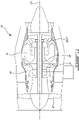
- FIG. 1 illustrates a gas turbine engine 10 of a type preferably provided for use in subsonic flight, generally comprising in serial flow communication a fan 12 through which ambient air is propelled, a multistage compressor 14 for pressurizing the air, a combustor 16 in which the compressed air is mixed with fuel and ignited for generating an annular stream of hot combustion gases, and a turbine section 18 for extracting energy from the combustion gases.
- engine 10 may be a turbo-fan engine.
- aspects of the present invention are applicable to other types of engines such as turbo-prop and turbo-shaft for example.
- Turbine section 18 may include one or more bladed disc assemblies 17.
- bladed disc assembly 17 may be part of a high-pressure turbine section of engine 10 and may be drivingly coupled to high-pressure shaft 26 of engine 10.
- bladed disc assembly 17 may be part of a low-pressure turbine section of engine 10 and may be drivingly coupled to low-pressure shaft 27 of engine 10.
- High-pressure shaft 26 and low-pressure shaft 27 may extend axially along central axis CA of engine 10 and may be substantially coaxial.
- FIG. 2 is an enlarged cross-sectional view of part of the turbine section 18 of engine 10.
- FIG. 3 is a perspective view of part of turbine section 18 shown in FIG. 2 .
- Bladed disc assembly 17 may include bladed disc 20 drivingly connected to rotor 22.
- bladed disc 20 may be connected for torque transfer and common rotation with rotor 22.
- Bladed disc 20 may be a turbine disc.
- aspects of this disclosure are applicable to other types of bladed discs that are not necessarily part of turbine section 18 of engine 10.
- blade disc 20 may be part of compressor section 14 of engine 10.
- Bladed disc 20 may include a hub and a plurality of blades extending radially outwardly from the hub and being circumferentially distributed about the hub.
- Bladed disc assembly 17 may be a turbine assembly.
- the term "rotor" is intended to encompass one or more rotatable components (e.g., shaft(s) and/or other bladed disc(s)) of engine 10 drivingly connected to bladed disc 20 to allow torque transfer between bladed disc 20 and rotor 22.
- rotor 22 may include another bladed disc drivingly connected to low-pressure shaft 27.
- rotor 22 may include a plurality of drivingly connected turbine discs drivingly connected to low-pressure shaft 27.
- Bladed disc 20 may be rotatably driven by the flow of combustion gases impinging on the blades of bladed disc 20 and the resulting torque generated by bladed disc 20 may be transferred to low-pressure shaft 27 via rotor 22 (e.g., turbine or other bladed disc).
- bladed disc 20 may be indirectly connected to low-pressure shaft 27 via rotor 22 as an intermediate component.
- low-pressure shaft 27 may be drivingly connected to rotor 22 by means of a splined connection having external splines 28 formed on low-pressure shaft 27 and complementary internal splines 30 formed on rotor 22.
- Bladed disc 20 may be secured to rotor 22 by means of nut 32 engaged with rotor 22 such that portion 34 of bladed disc 20 may be secured (e.g., clamped) between rotor 22 and shoulder 36 of nut 32.
- the shoulder 36 may have a generally circular periphery with one or more recesses 60 formed therein.
- Nut 32 may be engaged with rotor 22 to allow clamping of portion 34 of bladed disc 20 between rotor 22 and shoulder 36 of nut 32.
- Nut 32 may include threads 44 formed on nut 32 for threadable engagement with complementary threads 46 of rotor 22 such that nut 32 may be threadably engaged with rotor 22 and torque to a suitable preload.
- Threads 44 on nut 32 may be internal threads and threads 46 on rotor 22 may be external threads. Shoulder 36 of nut 32 may be substantially encased by deformable retainer 38. Nut 32 may be substantially disposed inside central bore 40 of bladed disc 20. Central bore 40 may be defined in the hub of bladed disc 20.
- the engagement of nut 32 with rotor 22 may include one or more intermediated components clamped between nut 32 and rotor 22.
- spacer 42 may be disposed between rotor 22 and nut 32. The combination of nut 32, deformable retainer 38, and spacer 42 may be disposed inside central bore 40 of bladed disc 20.
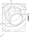
- FIG. 4 is a perspective view of a portion of the rotor 22.
- the portion is configured to engage with the nut 32 and allow interlocking with the deformable retainer 38.
- the nut 32 may threadably engage with the rotor 22 via externally threaded portion 46 on the rotor 22.
- the deformable retainer 38 may engage with the rotor 22 via keyways 69 formed in externally threaded portion 46 and complementary tabs 71 (see FIG. 7A ) on the deformable retainer 38.
- FIG. 5 is an enlarged cross-sectional view of part of another bladed disc assembly 17 where like elements have been identified using like reference numerals.
- FIG. 6 is a perspective view of an exemplary nut 32.
- One or more recesses 60 may be formed in shoulder 36 of nut 32.
- shoulder 36 may be scalloped.
- each recess 60 may be substantially axially tapered with respect to a direction parallel with central axis 64 of nut 32. In some embodiments, the direction may be towards a portion of nut 32 distal from shoulder 36.
- Nut 32 may include locking portion 66 located adjacent to shoulder 36 having recesses 60. Locking portion 66 may engage with tool 68 (shown in FIG. 8 ) for deforming retainer 38 such that the rotation of a portion of tool 68 relative to nut 32 is hindered during use of tool 68.
- locking portion 66 may have an hexagonal (or other non-circular) outer cross-sectional profile transverse to the central axis 64 of nut 32.
- Nut 32 may have a tool-engagement portion (e.g., threaded portion 72) located adjacent locking portion 66.
- the tool-engagement portion may permit engagement of tool 68 with nut 32 to facilitate the driving of tool 68 relative to nut 32 when causing deformation of retainer 38.
- the tool-engagement portion of nut 32 may include threaded portion 72 for use with tool 68.
- Threaded portion 72 may have external threads but it is understood that threaded portion 72 may instead have internal threads.
- First threaded portion 44 of nut 32 and second threaded portion 72 of nut 32 may be disposed at opposite axial ends of nut 32 with respect to central axis 64 of nut 32.
- Nut 32 can have central passage 70 defined therethrough.
- central passage 70 can have a diameter that is larger than at least part of low-pressure shaft 27 to permit nut 32 to be inserted over the applicable part of low-pressure shaft 27 as shown in FIG. 5 .
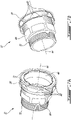
- FIG. 7A and FIG. 7B are perspective views of an exemplary nut 32 in combination with the undeformed deformable retainer 38.
- Retainer 38 may substantially encase shoulder 36 of nut 32 in such a manner as to cover recesses 60 formed in shoulder 36.
- Deformable retainer 38 may be formed of a material that can be plastically deformed into recesses 60 defined in shoulder 36 by means of tool 68.
- retainer 38 may be made from a metallic material (e.g., steel) having a suitable ductility.
- Deformable retainer 38 in an undeformed state may be annular and cup-shaped and fit over shoulder 36 of nut 32.
- Deformable retainer 38 may overhang recesses 60 with a gap defined between the overhanging portion and the recesses 60.
- undeformed deformable retainer 38 may include a washer assembly.
- the washer assembly may have a deformable ring with opposing and substantially flat surfaces with a flat surface in substantial contact with the shoulder 36.
- the deformable ring may include a plurality of tabs extending radially inwardly from the inner circumference of the deformable ring. Such tabs may serve to extend into and engage with respective cooperating features formed in rotor 22 in order to rotatably lock the deformable ring onto rotor 22 and hinder rotation of the deformable ring relative to rotor 22.
- Such features formed in rotor 22 may, for example, be suitable keyways 69 formed in externally threaded portion 46 of rotor 22 for receiving the tabs.
- the washer assembly may include a retaining ring to prevent lateral movement of the deformable ring.
- the retaining ring may include a substantially hollow cylinder encasing the deformable ring and a portion of the nut 32.
- the retaining ring may have a tightening mechanism to increase radial forces on the encased deformable ring and portion of nut 32.
- Retainer 38 may have one or more tabs 71 extending radially inwardly from an annular portion of retainer 38. Such tabs 71 may serve to extend into and engage with respective cooperating features formed in rotor 22 in order to rotatably lock retainer 38 onto rotor 22 and hinder rotation of retainer 38 relative to rotor 22. Such features formed in rotor 22 may, for example, be suitable keyways 69 (see FIG. 4 ) formed in externally threaded portion 46 of rotor 22 for receiving tabs 71.
- retainer 38 may be secured to rotor 22 by way of retainer 38 being clamped between nut 32 and optional spacer 42 and also being hindered from rotating relative to rotor 22 by way of tabs 71 rotatably secured by keyways 69.
- FIG. 8 is perspective view of an exemplary tool 68 used to deform (e.g., crimp) deformable retainer 38 into recesses 60 formed in nut 32.
- Tool 68 may have inner shaft 76 slidingly receivable within hollow outer cylinder 78.
- Tool 68 may further include cap 80 covering one axial end of outer cylinder 78.
- Cap 80 may have a hole therethrough adapted to allow a portion of inner shaft 76 to pass therethrough.
- Tool 68 may include means to enable linear displacement of inner shaft 76 relative to outer cylinder 78.
- nut 82 may be threadably engaged with externally threaded portion 84 of inner shaft 76 through the hole in cap 80.
- Inner shaft 76 may have axial end 86 adapted to cooperate with means hindering rotation of inner shaft 76.
- outer axial end 86 may have a hexagonal cross-sectional profile adapted to engage with a suitable wrench.
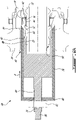
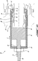
- FIGS. 9A and 9B are cross-sectional views of tool 68, shown inserted inside central bore 40 of bladed disc 20.
- FIG. 9A shows retainer 38 in an undeformed state prior to the (e.g., crimping) operation of tool 68.
- FIG. 9B shows retainer 38 deformed into recesses 60 formed in shoulder 36 of nut 32 after tool 68 has been used to deform (e.g., crimp) retainer 38.
- Inner shaft 76 of tool 68 may include means to engage with threaded portion 72 of nut 32 so that linear motion of inner shaft 76 relative to nut 32 may be hindered during operation.
- inner shaft 76 may have hollow axial end 90 having internally threaded portion 88 for engaging with threaded portion 72 of nut 32.
- Outer cylinder 78 may include means to slidingly engage with locking portion 66 of nut 32 so that rotation of outer cylinder 78 relative to nut 32 may be hindered but some linear motion of outer cylinder 78 along central axis 64 (see FIG. 6 ) of nut 32 may be allowed.
- locking portion 66 may have one or more outer flat faces (e.g., defining a hexagonal outer cross-sectional shape) adapted to mate with socket 92 defined inside hollow outer cylinder 78. Such mating between socket 92 and locking portion 66 may hinder rotation of outer cylinder 78 relative to nut 32 during operation.
- Outer cylinder 78 may have axial end 94 adapted to apply a biasing force on deformable retainer 38.
- the biasing force may cause deformable retainer 38 to deform into recesses 60 formed in shoulder 36 of nut 32.
- axial end 94 may have inner protrusions aligned with and adapted to cooperate with recesses 60 of nut 32 in order to push portions of retainer 38 into recesses 60 during deformation of retainer 38.
- axial end 94 may be tapered.
- Tool 68 or some other tool may be used to deform portions of retainer 38 into recesses 60 of nut 32 when nut 32 is threadably engaged with rotor 22, and retainer 38 is clamped between nut 32 and spacer 42.
- Outer cylinder 78 of tool 68 may have a cross-sectional dimension smaller than the diameter of central bore 40 of bladed disc 20, so that tool 68 can be received into central bore 40 to interface with nut 32.
- Tool 68 may deform retainer 38 into the recesses 60 formed in shoulder 36 of nut 32 by axially driving outer cylinder 78 of tool 68 against portions of retainer 38 overhanging recesses 60.
- the tapered end 94 of outer cylinder 78 may push the portion(s) of retainer 38 radially inwardly into respective recesses 60 as outer cylinder 78 is driven axially along arrow A so as to cause local plastic deformation of such portion(s) of retainer 38.
- Inner shaft 76 of tool 68 may be threadably engaged with externally threaded portion 72 of nut 32 in order to hinder axial movement of inner shaft 76 relative to nut 32.
- the engagement of inner shaft 76 with nut 32 via threads 88 and 72 may serve to hold tool 68 in place as outer cylinder 78 is driven to deform retainer 38.
- Outer cylinder 78 may be slid over inner shaft 76 and engaged with nut 32 so that outer cylinder 78 is engaged with locking portion 66 of nut 32 and axial end 86 of inner shaft 76 is passed through the hole of cap 80 of outer cylinder 78.
- cap 80 may be integrally formed with outer cylinder 78 to define a unitary construction.
- cap 80 and outer cylinder 78 may be separate components releasably assembled together.
- Nut 82 of tool 68 may be threadably engaged with external threads 84 on inner shaft 76. Nut 82 may then be turned so that the engagement of nut 82 with threads 84 applies a biasing force on outer cylinder 78 to cause translation of the outer cylinder 78 along arrow A toward shoulder 36 of nut 32. Such translation may cause axial end 94 of outer cylinder 78 to engage and deform portions of retainer 38 radially inwardly into recesses 60.
- FIG. 10 shows an end-on view of part of nut 32 viewed axially from the left side of FIG. 9B .
- FIG. 10 shows one recess 60 with which a portion of deformable retainer 38 is engaged after retainer 38 has been deformed into recesses 60 using tool 68.
- Deformable retainer 38 in a deformed state may have recesses 74 corresponding to recesses 60 formed on shoulder 36 of nut 32.
- Deformed retainer 38 may co-operatingly engage with a periphery of nut 32 in order to hinder rotation of nut 32 relative to rotor 22.
- FIG. 11 is a flow chart illustrating method 100 for securing bladed disc 20 to rotor 22.
- Method 100 may be performed using tool 68 or some other suitable tool. Accordingly, aspects of the use of tool 68 described above can be applicable to method 100.
- Method 100 may comprise:
- Bladed disc 20 may be secured for common rotation with rotor 22 by threadably engaging nut 32 with the rotor 22 to securely clamp bladed disc 20 between nut 32 and rotor 22 with or without intermediate spacer 42.
- Retainer 38 is engaged with rotor 22 to hinder rotation of retainer relative to rotor 22.
- the deforming may include driving a tool (e.g., outer cylinder 78 of tool 68) against retainer 38 to cause deformation of retainer 38.
- Driving the tool may include using nut 32 to apply a driving force on the tool.
- Nut 32 may be coaxial with rotor 22 and may be disposed inside central bore 40 of bladed disc 20.
- Method 100 may comprise axially driving the tool relative to nut 32 and radially deforming retainer 38 using the tool. Threaded portion 72 of nut 32 may be used to apply the biasing force on the tool.
- Method 100 may comprise securing the tool to nut 32 to hinder rotation of tool relative to nut 32 while driving the tool.
Landscapes
- Engineering & Computer Science (AREA)
- Mechanical Engineering (AREA)
- General Engineering & Computer Science (AREA)
- Turbine Rotor Nozzle Sealing (AREA)
Claims (15)
- Turbinenanordnung (17), umfassend:einen Rotor (22);eine Turbinenscheibe (20);eine Mutter (32), die in Gewindeeingriff mit dem Rotor (22) steht und die Turbinenscheibe (20) an dem Rotor (22) befestigt; und dadurch gekennzeichnet, dass sie Folgendes aufweist einen verformten Halter (38), der zusammenwirkend mit einem Umfang (36) der Mutter (32) in Eingriff steht und dazu konfiguriert ist, eine Drehung der Mutter (32) relativ zu dem Rotor (22) zu verhindern;wodurch der Halter (38) mit dem Rotor (22) in Eingriff steht, um eine Drehung des Halters (38) relativ zu dem Rotor (22) zu verhindern.
- Turbinenanordnung (17) nach Anspruch 1, wobei die Mutter (32) innerhalb einer zentralen Bohrung (40) der Turbinenscheibe (20) angeordnet ist.
- Turbinenanordnung (17) nach Anspruch 1 oder 2, wobei:die Turbinenscheibe (20) eine erste Turbinenscheibe (20) ist; undder Rotor (22) eine zweite Turbinenscheibe (22) ist.
- Turbinenanordnung (17) nach einem vorangehenden Anspruch, wobei:der Rotor (22) einen Außengewindeabschnitt (46) aufweist; unddie Mutter (32) einen Innengewindeabschnitt (44) aufweist, der mit dem Außengewindeabschnitt (46) des Rotors (22) in Eingriff steht.
- Turbinenanordnung (17) nach einem vorangehenden Anspruch, wobei:die Mutter (32) einen ersten Gewindeabschnitt (44) aufweist, der mit dem Rotor (22) in Gewindeeingriff steht; unddie Mutter (32) einen zweiten Gewindeabschnitt (72) zum Eingriff mit einem Werkzeug (68) zum Verformen des Halters (38) aufweist.
- Turbinenanordnung (17) nach Anspruch 5, wobei:der erste Gewindeabschnitt (44) der Mutter (32) ein oder der Innengewindeabschnitt (44) ist; undder zweite Gewindeabschnitt (72) der Mutter (32) ein Außengewindeabschnitt (72) ist.
- Turbinenanordnung (17) nach Anspruch 5 oder 6, wobei der erste und der zweite Gewindeabschnitt (44, 72) der Mutter (32) an entgegengesetzten axialen Enden der Mutter (32) angeordnet sind.
- Turbinenanordnung (17) nach einem der vorangehenden Ansprüche, wobei der Umfang (36) der Mutter (32) eine oder mehrere Aussparungen (60) umfasst, die mindestens teilweise von dem Halter (38) eingenommen werden.
- Turbinenanordnung (17) nach Anspruch 8, wobei die eine oder mehreren Aussparungen (60) axial verjüngt sind.
- Gasturbinentriebwerk (10), umfassend die Turbinenanordnung nach einem vorangehenden Anspruch, wobei die Turbinenscheibe (20) eine beschaufelte Scheibe (20) ist und der verformte Halter (38) zusammenwirkend mit einer Schulter (36) der Mutter (32) in Eingriff steht, die durch den Umfang (36) der Mutter (32) definiert ist.
- Verfahren zum Befestigen einer beschaufelten Scheibe (20) an einem Rotor (22), wobei das Verfahren umfasst:
Befestigen der beschaufelten Scheibe (20) an dem Rotor (22) durch Gewindeeingriff einer Mutter (32) mit dem Rotor (22); und Verformen eines Halters (38), um zu bewirken, dass der Halter (38) mit der Mutter (32) in Eingriff gelangt, wobei der Halter (38) mit dem Rotor (22) in Eingriff gebracht wird, um eine Drehung des Halters (38) relativ zu dem Rotor (22) zu verhindern, wobei das Verformen Antreiben eines Werkzeugs (68) gegen den Halter (38) umfasst, um eine Verformung des Halters (38) zu bewirken, wobei das Antreiben des Werkzeugs (68) Verwenden der Mutter (32) beinhaltet, um eine Kraft auf das Werkzeug (68) auszuüben. - Verfahren nach Anspruch 11, umfassend axiales Antreiben des Werkzeugs (68) relativ zu der Mutter (32) und radiales Verformen des Halters (38) mit dem Werkzeug (68).
- Verfahren nach Anspruch 11 oder 12, umfassend Verwenden eines Gewindeabschnitts (72) der Mutter (32), um die Kraft auf das Werkzeug (68) auszuüben.
- Verfahren nach einem der Ansprüche 11 bis 13, umfassend Befestigen des Werkzeugs (68) an der Mutter (32), um eine Drehung des Werkzeugs (68) relativ zu der Mutter (32) zu verhindern, während das Werkzeug (68) angetrieben wird.
- Gasturbinentriebwerk (10) nach Anspruch 10 oder Verfahren nach einem der Ansprüche 11 bis 14, wobei die Mutter (32) koaxial mit dem Rotor (22) ist und innerhalb einer zentralen Bohrung (40) der beschaufelten Scheibe (20) angeordnet ist.
Applications Claiming Priority (1)
| Application Number | Priority Date | Filing Date | Title |
|---|---|---|---|
| US16/437,085 US11105204B2 (en) | 2019-06-11 | 2019-06-11 | Turbine assembly |
Publications (2)
| Publication Number | Publication Date |
|---|---|
| EP3751096A1 EP3751096A1 (de) | 2020-12-16 |
| EP3751096B1 true EP3751096B1 (de) | 2022-08-31 |
Family
ID=71083530
Family Applications (1)
| Application Number | Title | Priority Date | Filing Date |
|---|---|---|---|
| EP20179235.5A Active EP3751096B1 (de) | 2019-06-11 | 2020-06-10 | Turbinenanordnung |
Country Status (3)
| Country | Link |
|---|---|
| US (1) | US11105204B2 (de) |
| EP (1) | EP3751096B1 (de) |
| CA (1) | CA3082807A1 (de) |
Families Citing this family (5)
| Publication number | Priority date | Publication date | Assignee | Title |
|---|---|---|---|---|
| KR102367002B1 (ko) * | 2020-08-28 | 2022-02-23 | 두산중공업 주식회사 | 타이로드의 인장 조립구조와 이를 포함하는 가스 터빈 및 타이로드의 인장 조립방법 |
| US11391157B1 (en) | 2021-03-23 | 2022-07-19 | Pratt & Whitney Canada Corp. | Damped rotor assembly |
| US11414993B1 (en) * | 2021-03-23 | 2022-08-16 | Pratt & Whitney Canada Corp. | Retaining assembly with anti-rotation feature |
| US11525464B2 (en) | 2021-03-23 | 2022-12-13 | Pratt & Whitney Canada Corp. | Rotor with centrifugally wedged damper |
| US11629596B1 (en) * | 2021-10-08 | 2023-04-18 | Pratt & Whitney Canada Corp. | Rotor assembly for a gas turbine engine and method for assembling same |
Family Cites Families (12)
| Publication number | Priority date | Publication date | Assignee | Title |
|---|---|---|---|---|
| US3622185A (en) * | 1969-06-02 | 1971-11-23 | Rosan Inc | Locking assembly for high-speed shafts |
| US4901523A (en) * | 1989-01-09 | 1990-02-20 | General Motors Corporation | Rotor for gas turbine engine |
| US5356236A (en) | 1991-09-25 | 1994-10-18 | Turbomeca | Device for connecting two elements in rotation |
| GB2455786B (en) | 2007-12-21 | 2009-11-18 | Rolls Royce Plc | Fastener assembly |
| FR2931874B1 (fr) | 2008-05-29 | 2010-06-25 | Snecma | Dispositif de blocage axial d'un palier de guidage d'arbre dans une turbomachine. |
| DE102008060571A1 (de) | 2008-12-04 | 2010-06-10 | Mtu Aero Engines Gmbh | Montagevorrichtung für ein Rotorsystem einer Axial-Strömungsmaschine |
| US8186939B2 (en) | 2009-08-25 | 2012-05-29 | Pratt & Whitney Canada Corp. | Turbine disc and retaining nut arrangement |
| US8517687B2 (en) | 2010-03-10 | 2013-08-27 | United Technologies Corporation | Gas turbine engine compressor and turbine section assembly utilizing tie shaft |
| US8979502B2 (en) | 2011-12-15 | 2015-03-17 | Pratt & Whitney Canada Corp. | Turbine rotor retaining system |
| US20150247406A1 (en) | 2012-09-07 | 2015-09-03 | Siemens Aktiengesellschaft | Method for assembling and disassembling a rotor having a number of rotor components of an axial flow turbomachine and such a rotor |
| GB201309952D0 (en) | 2013-06-04 | 2013-07-17 | Siemens Ag | Shaft arrangement |
| CN103603877B (zh) | 2013-11-21 | 2016-01-06 | 中国南方航空工业(集团)有限公司 | 锁紧装置 |
-
2019
- 2019-06-11 US US16/437,085 patent/US11105204B2/en active Active
-
2020
- 2020-06-09 CA CA3082807A patent/CA3082807A1/en active Pending
- 2020-06-10 EP EP20179235.5A patent/EP3751096B1/de active Active
Also Published As
| Publication number | Publication date |
|---|---|
| US11105204B2 (en) | 2021-08-31 |
| CA3082807A1 (en) | 2020-12-11 |
| US20200392849A1 (en) | 2020-12-17 |
| EP3751096A1 (de) | 2020-12-16 |
Similar Documents
| Publication | Publication Date | Title |
|---|---|---|
| EP3751096B1 (de) | Turbinenanordnung | |
| US11773751B1 (en) | Ceramic matrix composite blade track segment with pin-locating threaded insert | |
| US8382442B2 (en) | Controllable pitch blade non-ducted propeller for jet engine | |
| US9033666B2 (en) | Means for locking a sealing ring on a turbine disk | |
| KR960002024B1 (ko) | 구동 조립체의 임펠러 휠 잠금장치(Impeller Wheel Lock) | |
| US8152438B2 (en) | Installing a shaft in a bearing comprising a self-releasing nut | |
| US9835164B2 (en) | Compressor impeller assembly for a turbocharger | |
| US10920619B2 (en) | Annular casting and shrink-fitted part of an aircraft turbine engine | |
| US10001029B2 (en) | Bearing locking assemblies and methods of assembling the same | |
| US11629596B1 (en) | Rotor assembly for a gas turbine engine and method for assembling same | |
| US11480212B2 (en) | Nut locking feature | |
| EP3222857B1 (de) | Mechanische verbindung mit einem geflanschten halter | |
| EP4428341A2 (de) | Halteanordnung mit verdrehsicherung | |
| CA2935993C (en) | Spoke locking architecture | |
| EP2708698B1 (de) | Geblaserotoranordnung | |
| US9784130B2 (en) | Turbine engine comprising an upstream attachment means for a de-oiling pipe | |
| CA2857817C (en) | Fastening system for rotor hubs | |
| US20200200019A1 (en) | Turbomachine disc cover mounting arrangement | |
| US10274016B2 (en) | Turbine engine bearing assembly and method for assembling the same | |
| EP2594751A2 (de) | Bolzenarretierung |
Legal Events
| Date | Code | Title | Description |
|---|---|---|---|
| PUAI | Public reference made under article 153(3) epc to a published international application that has entered the european phase |
Free format text: ORIGINAL CODE: 0009012 |
|
| STAA | Information on the status of an ep patent application or granted ep patent |
Free format text: STATUS: THE APPLICATION HAS BEEN PUBLISHED |
|
| AK | Designated contracting states |
Kind code of ref document: A1 Designated state(s): AL AT BE BG CH CY CZ DE DK EE ES FI FR GB GR HR HU IE IS IT LI LT LU LV MC MK MT NL NO PL PT RO RS SE SI SK SM TR |
|
| AX | Request for extension of the european patent |
Extension state: BA ME |
|
| STAA | Information on the status of an ep patent application or granted ep patent |
Free format text: STATUS: REQUEST FOR EXAMINATION WAS MADE |
|
| 17P | Request for examination filed |
Effective date: 20210616 |
|
| RBV | Designated contracting states (corrected) |
Designated state(s): AL AT BE BG CH CY CZ DE DK EE ES FI FR GB GR HR HU IE IS IT LI LT LU LV MC MK MT NL NO PL PT RO RS SE SI SK SM TR |
|
| GRAP | Despatch of communication of intention to grant a patent |
Free format text: ORIGINAL CODE: EPIDOSNIGR1 |
|
| STAA | Information on the status of an ep patent application or granted ep patent |
Free format text: STATUS: GRANT OF PATENT IS INTENDED |
|
| INTG | Intention to grant announced |
Effective date: 20220317 |
|
| GRAS | Grant fee paid |
Free format text: ORIGINAL CODE: EPIDOSNIGR3 |
|
| GRAA | (expected) grant |
Free format text: ORIGINAL CODE: 0009210 |
|
| STAA | Information on the status of an ep patent application or granted ep patent |
Free format text: STATUS: THE PATENT HAS BEEN GRANTED |
|
| AK | Designated contracting states |
Kind code of ref document: B1 Designated state(s): AL AT BE BG CH CY CZ DE DK EE ES FI FR GB GR HR HU IE IS IT LI LT LU LV MC MK MT NL NO PL PT RO RS SE SI SK SM TR |
|
| REG | Reference to a national code |
Ref country code: CH Ref legal event code: EP Ref country code: GB Ref legal event code: FG4D |
|
| REG | Reference to a national code |
Ref country code: AT Ref legal event code: REF Ref document number: 1515421 Country of ref document: AT Kind code of ref document: T Effective date: 20220915 |
|
| REG | Reference to a national code |
Ref country code: DE Ref legal event code: R096 Ref document number: 602020004792 Country of ref document: DE |
|
| REG | Reference to a national code |
Ref country code: IE Ref legal event code: FG4D |
|
| REG | Reference to a national code |
Ref country code: LT Ref legal event code: MG9D |
|
| REG | Reference to a national code |
Ref country code: NL Ref legal event code: MP Effective date: 20220831 |
|
| PG25 | Lapsed in a contracting state [announced via postgrant information from national office to epo] |
Ref country code: SE Free format text: LAPSE BECAUSE OF FAILURE TO SUBMIT A TRANSLATION OF THE DESCRIPTION OR TO PAY THE FEE WITHIN THE PRESCRIBED TIME-LIMIT Effective date: 20220831 Ref country code: RS Free format text: LAPSE BECAUSE OF FAILURE TO SUBMIT A TRANSLATION OF THE DESCRIPTION OR TO PAY THE FEE WITHIN THE PRESCRIBED TIME-LIMIT Effective date: 20220831 Ref country code: NO Free format text: LAPSE BECAUSE OF FAILURE TO SUBMIT A TRANSLATION OF THE DESCRIPTION OR TO PAY THE FEE WITHIN THE PRESCRIBED TIME-LIMIT Effective date: 20221130 Ref country code: LV Free format text: LAPSE BECAUSE OF FAILURE TO SUBMIT A TRANSLATION OF THE DESCRIPTION OR TO PAY THE FEE WITHIN THE PRESCRIBED TIME-LIMIT Effective date: 20220831 Ref country code: LT Free format text: LAPSE BECAUSE OF FAILURE TO SUBMIT A TRANSLATION OF THE DESCRIPTION OR TO PAY THE FEE WITHIN THE PRESCRIBED TIME-LIMIT Effective date: 20220831 Ref country code: FI Free format text: LAPSE BECAUSE OF FAILURE TO SUBMIT A TRANSLATION OF THE DESCRIPTION OR TO PAY THE FEE WITHIN THE PRESCRIBED TIME-LIMIT Effective date: 20220831 |
|
| REG | Reference to a national code |
Ref country code: AT Ref legal event code: MK05 Ref document number: 1515421 Country of ref document: AT Kind code of ref document: T Effective date: 20220831 |
|
| PG25 | Lapsed in a contracting state [announced via postgrant information from national office to epo] |
Ref country code: PL Free format text: LAPSE BECAUSE OF FAILURE TO SUBMIT A TRANSLATION OF THE DESCRIPTION OR TO PAY THE FEE WITHIN THE PRESCRIBED TIME-LIMIT Effective date: 20220831 Ref country code: IS Free format text: LAPSE BECAUSE OF FAILURE TO SUBMIT A TRANSLATION OF THE DESCRIPTION OR TO PAY THE FEE WITHIN THE PRESCRIBED TIME-LIMIT Effective date: 20221231 Ref country code: HR Free format text: LAPSE BECAUSE OF FAILURE TO SUBMIT A TRANSLATION OF THE DESCRIPTION OR TO PAY THE FEE WITHIN THE PRESCRIBED TIME-LIMIT Effective date: 20220831 Ref country code: GR Free format text: LAPSE BECAUSE OF FAILURE TO SUBMIT A TRANSLATION OF THE DESCRIPTION OR TO PAY THE FEE WITHIN THE PRESCRIBED TIME-LIMIT Effective date: 20221201 |
|
| PG25 | Lapsed in a contracting state [announced via postgrant information from national office to epo] |
Ref country code: SM Free format text: LAPSE BECAUSE OF FAILURE TO SUBMIT A TRANSLATION OF THE DESCRIPTION OR TO PAY THE FEE WITHIN THE PRESCRIBED TIME-LIMIT Effective date: 20220831 Ref country code: RO Free format text: LAPSE BECAUSE OF FAILURE TO SUBMIT A TRANSLATION OF THE DESCRIPTION OR TO PAY THE FEE WITHIN THE PRESCRIBED TIME-LIMIT Effective date: 20220831 Ref country code: PT Free format text: LAPSE BECAUSE OF FAILURE TO SUBMIT A TRANSLATION OF THE DESCRIPTION OR TO PAY THE FEE WITHIN THE PRESCRIBED TIME-LIMIT Effective date: 20230102 Ref country code: ES Free format text: LAPSE BECAUSE OF FAILURE TO SUBMIT A TRANSLATION OF THE DESCRIPTION OR TO PAY THE FEE WITHIN THE PRESCRIBED TIME-LIMIT Effective date: 20220831 Ref country code: DK Free format text: LAPSE BECAUSE OF FAILURE TO SUBMIT A TRANSLATION OF THE DESCRIPTION OR TO PAY THE FEE WITHIN THE PRESCRIBED TIME-LIMIT Effective date: 20220831 Ref country code: CZ Free format text: LAPSE BECAUSE OF FAILURE TO SUBMIT A TRANSLATION OF THE DESCRIPTION OR TO PAY THE FEE WITHIN THE PRESCRIBED TIME-LIMIT Effective date: 20220831 Ref country code: AT Free format text: LAPSE BECAUSE OF FAILURE TO SUBMIT A TRANSLATION OF THE DESCRIPTION OR TO PAY THE FEE WITHIN THE PRESCRIBED TIME-LIMIT Effective date: 20220831 |
|
| PG25 | Lapsed in a contracting state [announced via postgrant information from national office to epo] |
Ref country code: SK Free format text: LAPSE BECAUSE OF FAILURE TO SUBMIT A TRANSLATION OF THE DESCRIPTION OR TO PAY THE FEE WITHIN THE PRESCRIBED TIME-LIMIT Effective date: 20220831 Ref country code: EE Free format text: LAPSE BECAUSE OF FAILURE TO SUBMIT A TRANSLATION OF THE DESCRIPTION OR TO PAY THE FEE WITHIN THE PRESCRIBED TIME-LIMIT Effective date: 20220831 |
|
| REG | Reference to a national code |
Ref country code: DE Ref legal event code: R097 Ref document number: 602020004792 Country of ref document: DE |
|
| PG25 | Lapsed in a contracting state [announced via postgrant information from national office to epo] |
Ref country code: NL Free format text: LAPSE BECAUSE OF FAILURE TO SUBMIT A TRANSLATION OF THE DESCRIPTION OR TO PAY THE FEE WITHIN THE PRESCRIBED TIME-LIMIT Effective date: 20220831 Ref country code: AL Free format text: LAPSE BECAUSE OF FAILURE TO SUBMIT A TRANSLATION OF THE DESCRIPTION OR TO PAY THE FEE WITHIN THE PRESCRIBED TIME-LIMIT Effective date: 20220831 |
|
| PLBE | No opposition filed within time limit |
Free format text: ORIGINAL CODE: 0009261 |
|
| STAA | Information on the status of an ep patent application or granted ep patent |
Free format text: STATUS: NO OPPOSITION FILED WITHIN TIME LIMIT |
|
| P01 | Opt-out of the competence of the unified patent court (upc) registered |
Effective date: 20230530 |
|
| 26N | No opposition filed |
Effective date: 20230601 |
|
| PG25 | Lapsed in a contracting state [announced via postgrant information from national office to epo] |
Ref country code: SI Free format text: LAPSE BECAUSE OF FAILURE TO SUBMIT A TRANSLATION OF THE DESCRIPTION OR TO PAY THE FEE WITHIN THE PRESCRIBED TIME-LIMIT Effective date: 20220831 |
|
| PG25 | Lapsed in a contracting state [announced via postgrant information from national office to epo] |
Ref country code: MC Free format text: LAPSE BECAUSE OF FAILURE TO SUBMIT A TRANSLATION OF THE DESCRIPTION OR TO PAY THE FEE WITHIN THE PRESCRIBED TIME-LIMIT Effective date: 20220831 |
|
| PG25 | Lapsed in a contracting state [announced via postgrant information from national office to epo] |
Ref country code: MC Free format text: LAPSE BECAUSE OF FAILURE TO SUBMIT A TRANSLATION OF THE DESCRIPTION OR TO PAY THE FEE WITHIN THE PRESCRIBED TIME-LIMIT Effective date: 20220831 |
|
| REG | Reference to a national code |
Ref country code: CH Ref legal event code: PL |
|
| REG | Reference to a national code |
Ref country code: BE Ref legal event code: MM Effective date: 20230630 |
|
| PG25 | Lapsed in a contracting state [announced via postgrant information from national office to epo] |
Ref country code: LU Free format text: LAPSE BECAUSE OF NON-PAYMENT OF DUE FEES Effective date: 20230610 |
|
| REG | Reference to a national code |
Ref country code: IE Ref legal event code: MM4A |
|
| PG25 | Lapsed in a contracting state [announced via postgrant information from national office to epo] |
Ref country code: LU Free format text: LAPSE BECAUSE OF NON-PAYMENT OF DUE FEES Effective date: 20230610 |
|
| PG25 | Lapsed in a contracting state [announced via postgrant information from national office to epo] |
Ref country code: IE Free format text: LAPSE BECAUSE OF NON-PAYMENT OF DUE FEES Effective date: 20230610 |
|
| PG25 | Lapsed in a contracting state [announced via postgrant information from national office to epo] |
Ref country code: IE Free format text: LAPSE BECAUSE OF NON-PAYMENT OF DUE FEES Effective date: 20230610 Ref country code: CH Free format text: LAPSE BECAUSE OF NON-PAYMENT OF DUE FEES Effective date: 20230630 |
|
| PG25 | Lapsed in a contracting state [announced via postgrant information from national office to epo] |
Ref country code: IT Free format text: LAPSE BECAUSE OF FAILURE TO SUBMIT A TRANSLATION OF THE DESCRIPTION OR TO PAY THE FEE WITHIN THE PRESCRIBED TIME-LIMIT Effective date: 20220831 Ref country code: BE Free format text: LAPSE BECAUSE OF NON-PAYMENT OF DUE FEES Effective date: 20230630 |
|
| PG25 | Lapsed in a contracting state [announced via postgrant information from national office to epo] |
Ref country code: BG Free format text: LAPSE BECAUSE OF FAILURE TO SUBMIT A TRANSLATION OF THE DESCRIPTION OR TO PAY THE FEE WITHIN THE PRESCRIBED TIME-LIMIT Effective date: 20220831 |
|
| PG25 | Lapsed in a contracting state [announced via postgrant information from national office to epo] |
Ref country code: BG Free format text: LAPSE BECAUSE OF FAILURE TO SUBMIT A TRANSLATION OF THE DESCRIPTION OR TO PAY THE FEE WITHIN THE PRESCRIBED TIME-LIMIT Effective date: 20220831 |
|
| PGFP | Annual fee paid to national office [announced via postgrant information from national office to epo] |
Ref country code: DE Payment date: 20250520 Year of fee payment: 6 |
|
| PGFP | Annual fee paid to national office [announced via postgrant information from national office to epo] |
Ref country code: GB Payment date: 20250520 Year of fee payment: 6 |
|
| PGFP | Annual fee paid to national office [announced via postgrant information from national office to epo] |
Ref country code: FR Payment date: 20250520 Year of fee payment: 6 |
|
| PG25 | Lapsed in a contracting state [announced via postgrant information from national office to epo] |
Ref country code: CY Free format text: LAPSE BECAUSE OF FAILURE TO SUBMIT A TRANSLATION OF THE DESCRIPTION OR TO PAY THE FEE WITHIN THE PRESCRIBED TIME-LIMIT; INVALID AB INITIO Effective date: 20200610 |
|
| PG25 | Lapsed in a contracting state [announced via postgrant information from national office to epo] |
Ref country code: HU Free format text: LAPSE BECAUSE OF FAILURE TO SUBMIT A TRANSLATION OF THE DESCRIPTION OR TO PAY THE FEE WITHIN THE PRESCRIBED TIME-LIMIT; INVALID AB INITIO Effective date: 20200610 |
|
| PG25 | Lapsed in a contracting state [announced via postgrant information from national office to epo] |
Ref country code: TR Free format text: LAPSE BECAUSE OF FAILURE TO SUBMIT A TRANSLATION OF THE DESCRIPTION OR TO PAY THE FEE WITHIN THE PRESCRIBED TIME-LIMIT Effective date: 20220831 |