EP4428341A2 - Halteanordnung mit verdrehsicherung - Google Patents
Halteanordnung mit verdrehsicherung Download PDFInfo
- Publication number
- EP4428341A2 EP4428341A2 EP24187537.6A EP24187537A EP4428341A2 EP 4428341 A2 EP4428341 A2 EP 4428341A2 EP 24187537 A EP24187537 A EP 24187537A EP 4428341 A2 EP4428341 A2 EP 4428341A2
- Authority
- EP
- European Patent Office
- Prior art keywords
- keys
- rotating component
- key
- retention assembly
- retaining ring
- Prior art date
- Legal status (The legal status is an assumption and is not a legal conclusion. Google has not performed a legal analysis and makes no representation as to the accuracy of the status listed.)
- Granted
Links
Images






Classifications
-
- F—MECHANICAL ENGINEERING; LIGHTING; HEATING; WEAPONS; BLASTING
- F01—MACHINES OR ENGINES IN GENERAL; ENGINE PLANTS IN GENERAL; STEAM ENGINES
- F01D—NON-POSITIVE DISPLACEMENT MACHINES OR ENGINES, e.g. STEAM TURBINES
- F01D5/00—Blades; Blade-carrying members; Heating, heat-insulating, cooling or antivibration means on the blades or the members
- F01D5/02—Blade-carrying members, e.g. rotors
- F01D5/025—Fixing blade carrying members on shafts
-
- F—MECHANICAL ENGINEERING; LIGHTING; HEATING; WEAPONS; BLASTING
- F01—MACHINES OR ENGINES IN GENERAL; ENGINE PLANTS IN GENERAL; STEAM ENGINES
- F01D—NON-POSITIVE DISPLACEMENT MACHINES OR ENGINES, e.g. STEAM TURBINES
- F01D5/00—Blades; Blade-carrying members; Heating, heat-insulating, cooling or antivibration means on the blades or the members
- F01D5/30—Fixing blades to rotors; Blade roots ; Blade spacers
- F01D5/3007—Fixing blades to rotors; Blade roots ; Blade spacers of axial insertion type
- F01D5/3015—Fixing blades to rotors; Blade roots ; Blade spacers of axial insertion type with side plates
-
- F—MECHANICAL ENGINEERING; LIGHTING; HEATING; WEAPONS; BLASTING
- F01—MACHINES OR ENGINES IN GENERAL; ENGINE PLANTS IN GENERAL; STEAM ENGINES
- F01D—NON-POSITIVE DISPLACEMENT MACHINES OR ENGINES, e.g. STEAM TURBINES
- F01D5/00—Blades; Blade-carrying members; Heating, heat-insulating, cooling or antivibration means on the blades or the members
- F01D5/02—Blade-carrying members, e.g. rotors
- F01D5/026—Shaft to shaft connections
-
- F—MECHANICAL ENGINEERING; LIGHTING; HEATING; WEAPONS; BLASTING
- F01—MACHINES OR ENGINES IN GENERAL; ENGINE PLANTS IN GENERAL; STEAM ENGINES
- F01D—NON-POSITIVE DISPLACEMENT MACHINES OR ENGINES, e.g. STEAM TURBINES
- F01D5/00—Blades; Blade-carrying members; Heating, heat-insulating, cooling or antivibration means on the blades or the members
- F01D5/02—Blade-carrying members, e.g. rotors
- F01D5/06—Rotors for more than one axial stage, e.g. of drum or multiple disc type; Details thereof, e.g. shafts, shaft connections
- F01D5/066—Connecting means for joining rotor-discs or rotor-elements together, e.g. by a central bolt, by clamps
-
- F—MECHANICAL ENGINEERING; LIGHTING; HEATING; WEAPONS; BLASTING
- F05—INDEXING SCHEMES RELATING TO ENGINES OR PUMPS IN VARIOUS SUBCLASSES OF CLASSES F01-F04
- F05D—INDEXING SCHEME FOR ASPECTS RELATING TO NON-POSITIVE-DISPLACEMENT MACHINES OR ENGINES, GAS-TURBINES OR JET-PROPULSION PLANTS
- F05D2220/00—Application
- F05D2220/30—Application in turbines
- F05D2220/32—Application in turbines in gas turbines
-
- F—MECHANICAL ENGINEERING; LIGHTING; HEATING; WEAPONS; BLASTING
- F05—INDEXING SCHEMES RELATING TO ENGINES OR PUMPS IN VARIOUS SUBCLASSES OF CLASSES F01-F04
- F05D—INDEXING SCHEME FOR ASPECTS RELATING TO NON-POSITIVE-DISPLACEMENT MACHINES OR ENGINES, GAS-TURBINES OR JET-PROPULSION PLANTS
- F05D2230/00—Manufacture
- F05D2230/60—Assembly methods
-
- F—MECHANICAL ENGINEERING; LIGHTING; HEATING; WEAPONS; BLASTING
- F05—INDEXING SCHEMES RELATING TO ENGINES OR PUMPS IN VARIOUS SUBCLASSES OF CLASSES F01-F04
- F05D—INDEXING SCHEME FOR ASPECTS RELATING TO NON-POSITIVE-DISPLACEMENT MACHINES OR ENGINES, GAS-TURBINES OR JET-PROPULSION PLANTS
- F05D2240/00—Components
- F05D2240/20—Rotors
- F05D2240/24—Rotors for turbines
-
- F—MECHANICAL ENGINEERING; LIGHTING; HEATING; WEAPONS; BLASTING
- F05—INDEXING SCHEMES RELATING TO ENGINES OR PUMPS IN VARIOUS SUBCLASSES OF CLASSES F01-F04
- F05D—INDEXING SCHEME FOR ASPECTS RELATING TO NON-POSITIVE-DISPLACEMENT MACHINES OR ENGINES, GAS-TURBINES OR JET-PROPULSION PLANTS
- F05D2250/00—Geometry
- F05D2250/10—Two-dimensional
- F05D2250/18—Two-dimensional patterned
- F05D2250/182—Two-dimensional patterned crenellated, notched
-
- F—MECHANICAL ENGINEERING; LIGHTING; HEATING; WEAPONS; BLASTING
- F05—INDEXING SCHEMES RELATING TO ENGINES OR PUMPS IN VARIOUS SUBCLASSES OF CLASSES F01-F04
- F05D—INDEXING SCHEME FOR ASPECTS RELATING TO NON-POSITIVE-DISPLACEMENT MACHINES OR ENGINES, GAS-TURBINES OR JET-PROPULSION PLANTS
- F05D2260/00—Function
- F05D2260/30—Retaining components in desired mutual position
- F05D2260/36—Retaining components in desired mutual position by a form fit connection, e.g. by interlocking
Definitions
- the invention relates generally to gas turbine engines and, more particularly, to a retaining assembly between rotating components in a gas turbine engine that includes an anti-rotation feature.
- Retaining assemblies including for instance threaded fasteners that are locked in place by key washers and retaining rings, are often employed in gas turbine engines to interconnect two rotating components.
- a fastener such as a nut is used to axially fasten the two components together while a key washer and retaining ring ensure the fastener remains in place and cannot rotate relative to the component(s) with which it is threadedly engaged.
- Key washers may provide both radial and axial retention forces for the retaining ring relative to a general rotational axis of the rotating components. To provide both such retention forces, the key washer requires adequate spacing within the gas turbine engine for its retention features. Modern gas turbine engines are typically quite compact, leading to tight spacing for the various components within.
- the retention features of a typical key washer often include overhanging parts, which may be subjected to high radial loads in gas turbine engines rotating at high operational speeds, for instance at or over 30,000 RPM.
- a retention assembly for interconnecting rotating components in a gas turbine engine, comprising: a first rotating component defining a central rotation axis; a second rotating component rotatable about the central rotation axis, the second rotating component including an engagement portion defining protrusions circumferentially spaced apart and extending axially from the second rotating component; a threaded fastener axially retaining the second rotating component to the first rotating component, the threaded fastener having key-receiving slots circumferentially spaced apart and extending radially into an outer circumferential surface of the threaded fastener, and a groove extending circumferentially about the threaded fastener within the outer circumferential surface; a key washer mounted to the threaded fastener, the key washer being annular and defining a first axial surface and a second axial surface axially spaced apart from each other, the key washer having a first set of keys circumferentially spaced apart and
- the retention assembly as defined above and herein may further include, in whole or in part, and in any combination, one or more of the following features.
- the key-receiving slots are proximate a first axial edge of the threaded fastener and the groove is proximate a second axial edge of the threaded fastener.
- the second set of keys includes first portions projecting axially from the second axial surface of the key washer and second portions projecting radially inwardly from the first portions.
- the key washer includes ninety-degree bends between the first portions and the second portions of the second set of keys.
- the second rotating component includes slots defined between adjacent protrusions, the second set of keys received in said slots.
- the engagement portion of the second rotating component includes the slots between the adjacent protrusions.
- the second rotating components includes an annular flange including the protrusions, the annular flange further including cutouts arranged about an outer circumference of the annular flange.
- the cutouts are scallop-shaped.
- the retention assembly as defined above and herein may further include, in whole or in part, and in any combination, one or more of the following features.
- the first rotating component includes an engagement portion with slots circumferentially spaced about an outer circumference thereof, and wherein the engagement portion of the second rotating component includes retention tabs extending radially inwardly, the retention tabs received in the slots of the engagement portion of the first rotating component.
- the key-receiving slots are proximate a first axial edge of the threaded fastener and the groove in the threaded fastener is proximate a second axial edge of the threaded fastener.
- the second set of keys includes first portions projecting axially from an axial surface of the key washer and second portions projecting radially inwardly from the first portions.
- the retaining ring is axially constrained between the second portions of the second set of keys and a body of the key washer.
- the radial gap is defined by a radial distance between a radially inner surface of the protrusions and a radially inner surface of the first portions of the second set of keys.
- the second rotating component has an annular flange including the protrusions, the annular flange further including cutouts arranged about an outer circumference of the annular flange.
- the cutouts are scallop-shaped.
- At least one of the cutouts is circumferentially located between pairs of the slots receiving the second set of keys.
- the engagement portion of the second rotating component further includes slots between adjacent protrusions, the second set of keys received in said slots.
- the first set of keys are arranged in adjacent pairs about the radially inner surface of the key washer, with slots separating respective first set of keys in each said adjacent pair.
- the first rotating component is a rotor disc of a high pressure turbine of the gas turbine engine
- the second component is a rotor disc cover plate mounted to the rotor disc by the retention assembly.
- a method for assembling a retention assembly in a gas turbine engine comprising: mounting a rotor disc cover plate to a rotor disc; positioning a retaining ring within a groove of a nut; mounting the nut to the rotor disc; torqueing the nut to fasten the rotor disc cover plate to the rotor disc; mounting a key washer over the nut; positioning a first set of keys of the key washer within a plurality of key-receiving slots in the nut; positioning a second set of keys of the key washer within a plurality of slots in the rotor disc cover plate; axially retaining the retaining ring relative to a central longitudinal axis of the gas turbine engine via the second set of keys; and radially retaining the retaining ring relative to the central longitudinal axis of the gas turbine engine via protrusions protruding from the rotor disc cover plate.
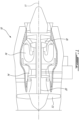
- FIG. 1 illustrates a gas turbine engine 10 of a type preferably provided for use in subsonic flight, generally comprising in serial flow communication a fan 12 through which ambient air is propelled, a compressor section 14 for pressurizing the air, a combustor 16 in which the compressed air is mixed with fuel and ignited for generating an annular stream of hot combustion gases, and a turbine section 18 for extracting energy from the combustion gases.
- a shaft 20 interconnects the fan 12, the compressor section 14 and the turbine section 18. While FIG. 1 shows gas turbine engine 10 to be a turbofan gas turbine engine, it is understood that the present disclosure is applicable to other types of gas turbine engines as well.
- a rotor assembly 22 which can be used in the gas turbine engine 10 of FIG. 1 or in any adequate type of gas turbine engine 10 is shown.
- the rotor assembly 22 is operable for rotation about a central longitudinal axis 11.
- the rotor assembly 22 is a high pressure turbine (HPT) stage of a multistage turbine section 18 rotating at over 30,000 RPM.
- HPT high pressure turbine
- the present disclosure may be applicable to other rotors or other rotating components within a gas turbine engine, as will be discussed in further detail below.
- the rotor assembly 22 includes a rotor disc 24 mounted around a drive shaft 20 (shown in FIG. 1 ).
- the rotor includes a hub portion 26 having a central bore 28 through which the drive shaft 20 is inserted.
- the rotor disc 24 includes a frustoconical web portion 30 extending generally radially from the hub portion 26.
- the rotor disc 24 also has two opposite axially facing faces 32, 34 with reference to the longitudinal axis 11. Opposite faces 32, 34 may be referred to as the first opposite face 32 and the second opposite face 34.
- the rotor disc 24 includes a rotor disc cover plate 36 mounted to the first opposite face 32.
- the rotor disc 24 includes an outer periphery portion 38 encircling the web portion 30.
- the rotor assembly 22 includes a plurality of circumferentially-disposed and radially extending blades 40 mounted in corresponding blade-receiving slots 42 provided in the outer periphery portion 38 for receiving roots of the blades 40.
- the number of blades 40 may vary, for instance based on the type of rotor assembly 22 or the type of engine 10.
- the slots 42 are designed to prevent the blades 40 from being ejected radially during rotation.
- Other components such as fixing rivets, spring plates, etc., may be provided in the rotor assembly 22, depending on the design.
- blades 40 that are made integral with the rotor, i.e. forming a monolithic assembly may be contemplated as well.
- the rotor disc cover plate 36 includes an inlet 44 ( Fig. 2 ) to provide a cooling flow to the blades 40 through an annular cooling channel 46 between the rotor disc cover plate 36 and the corresponding web portion 30.
- Other methods for cooling the blades 40 may be contemplated as well.
- various components such as a carbon seal runner 48 (shown in FIG. 3B ) may be positioned adjacent where the rotor disc cover plate 36 attaches to the rotor disc 24.
- the rotor disc cover plate 36 is mounted to the rotor disc 24, illustratively in front of the first opposite face's 32 web portion 30, via a retention assembly 50.
- the retention assembly 50 is operable to retain the rotor disc cover plate 36 to the rotor disc 24 while respecting the limited spacing provided within this section of the gas turbine engine 10, for instance due to the adjacent carbon seal runner 48.
- the retention assembly 50 may be operable to accommodate high rotational speeds of the rotating rotor disc 24, for instance speeds of 50,000 RPM or higher. While the shown retention assembly 50 is operable to retain the rotor disc cover plate 36 to the rotor disc 24 of the rotor assembly 22, it is understood that this is an exemplary embodiment.
- the retention assembly 50 may be used to retain various other rotating components within the gas turbine engine 10, for instance where spacing is limited and/or in cases where rotational speeds reach or exceed high values such as 30,000 RPM or more.
- the retention assembly 50 as per the present disclosure may be used to interconnect a first rotating component (illustratively the rotor disc 24) with a second rotating component (illustratively the rotor disc cover plate 36) disposed about a central rotation axis (illustratively the central longitudinal axis 11 of the gas turbine engine 10). It is understood that other rotating components within the gas turbine engine rotating about other central rotational axes may benefit from the herein described retention assembly 50 as well.
- the retention assembly 50 is operable to fasten the rotor disc cover plate 36 to the rotor disc 24.
- a rotor disc engagement portion 60 of the rotor disc 24 is operable to receive and engage with a cover plate engagement portion 70 of the rotor disc cover plate 36.
- a threaded fastener illustratively a nut 80, is rotatably mounted to the rotor disc engagement portion 70 upon mounting of the rotor disc cover plate 36 to fasten the rotor disc cover plate 36 to the rotor disc 24.
- a key washer 90 is mounted to the nut 80 to prevent the nut 80 from rotating, i.e. to ensure the rotor disc cover plate 36 remains fastened to the rotor disc 24.
- the retention assembly 50 may include other types of fasteners to ensure the rotor disc cover plate 36 remains fastened to the rotor disc 24.
- a retaining ring 100 is mounted to the nut 80 to load the retention assembly 50. As will be discussed in further detail below, the axial and radial retention forces applied to the retaining ring 100 relative to the longitudinal axis 11 are split between the key washer 90 and the cover plate engagement portion 70 of the rotor disc cover plate 36.
- the rotor disc engagement portion 60 of the rotor disc 24 is illustratively a raised annular shoulder disposed about the longitudinal axis 11 between the hub portion 26 and the web portion 30.
- the rotor disc engagement portion 60 includes a plurality of cover plate-receiving slots 62 circumferentially arranged about the rotor disc engagement portion 60.
- the slots 62 are operable to engage with corresponding elements of the mounted rotor disc cover plate 36, as will be discussed in further detail below.
- the number, size and shape of slots 62 may vary, for instance based on the geometry of the corresponding components of the rotor disc cover plate 36.
- the rotor disc 24 further includes a first set of threads 64 circumferentially disposed about the rotor disc engagement portion 60.
- the first set of threads 64 is operable to engage with a corresponding set of threads disposed on the nut 80 for secured rotational engagement, as will be discussed in further detail below.
- the first set of threads 64 may be replaced by other suitable fastening elements based on the type of fastener selected.
- four slots 62 are axisymmetrically arranged about the rotor disc engagement portion 60 with reference to the longitudinal axis 11, although other arrangements may be contemplated as well.
- the cover plate engagement portion 70 of the rotor disc cover plate 36 is shown to be an annular collar portion of the rotor disc cover plate 36, although other arrangements may be contemplated as well.
- the cover plate engagement portion 70 is disposed about an opening 71 in the rotor disc cover plate 36 for mounting over the rotor disc's 24 hub portion 26, as will be discussed in further detail below.
- the cover plate engagement portion 70 includes a plurality of retention tabs 72 arranged about an inner circumference of the cover plate engagement portion 70 and protruding axially relative to the longitudinal axis 11. In the depicted embodiment, four retention tabs 72 are axisymmetrically disposed about the inner circumference of the cover plate engagement portion 70, although other arrangements may be contemplated as well.
- the number, arrangement and geometry of the retention tabs 72 correspond to the number, shape and geometry of the slots 62 of the rotor disc engagement portion 60.
- the retention tabs 72 received within the slots 62 to prevent rotation of the rotor disc cover plate 36 relative to the rotor disc 24 while allowing the rotor disc cover plate 36 to rotate with the rotor disc 24 as the gas turbine engine 10 operates.
- said number, shape and geometry of the slots 62 and corresponding retention tabs 72 may vary.
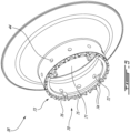
- the cover plate engagement portion 70 further includes an annular flange 73 disposed about the outer circumference of the cover plate engagement portion 70.
- the annular flange 73 includes a plurality of protrusions 74 spaced apart an outer circumference of the annular flange 73 and protruding or extending axially from an axial surface of the annular flange 73 relative to the longitudinal axis 11.
- adjacent pairs of protrusions 74 define cover plate slots 75 therebetween.
- the cover plate slots 75 are operable to engage with elements of the key washer 90 to prevent rotation of the various components.
- the size and shape of the cover plate slots 75 may vary, for instance based on the geometry of the corresponding elements of the key washer 90.
- between said adjacent pairs of protrusions 74 are defined scalloped cutouts 76, for instance to reduce stresses within the rotor disc cover plate 36 and/or to provide access to the retaining ring 100 once the retention assembly 50 is assembled.
- Other cutout shapes may be contemplated as well.
- the protrusions 74 are operable to engage with the retaining ring 100 to retain the retaining ring 100 in place in a radial direction relative to the longitudinal axis 11.
- Other numbers, sizes, geometries and positions of the various retention tabs 72, protrusions 74, cover plate slots 75 and scalloped cutouts 76 may be contemplated as well.
- an exemplary threaded fastener for the retention assembly 50 is a nut 80.
- the nut 80 resembles an annular ring having a radially inner surface 81 and a radially outer surface 82 or outer circumferential surface 82, each extending between a first axial edge 83 and a second axial edge 84 relative to the longitudinal axis 11.
- a second set of threads 85 are disposed along the radially inner surface 81 of the nut. The second set of threads 85 corresponds with and are thus engageable to the first set of threads 64 on the rotor disc engagement portion 60 of the rotor disc 24.
- the nut 80 is rotatably securable to the rotor disc 24 at the rotor disc engagement portion 60.
- the diameter and pitch of the first and second sets of threads 64, 85 may vary, for instance based on the specific application for the retention assembly 50.
- the shown nut 80 further incudes a plurality of key-receiving slots 86 circumferentially spaced apart about the radially outer surface 82 of the nut 80 towards the first axial edge 83 of the nut 80.
- the key-receiving slots 86 are engageable with elements of the key washer 90 to prevent rotation, i.e. unfastening, of the nut 80.
- the key-receiving slots 86 in the nut 80 are open towards the first axial edge 83 to facilitate such engagement.
- the number, size, position and shape of the key-receiving slots 86 may vary, for instance based on the geometry of the key washer 90.
- the nut 80 further incudes a groove 87 extending circumferentially about the outer circumferential surface 82 of the nut 80 towards the second axial edge 84 of the nut 80.
- the retaining ring 100 is insertable in the groove 87 of the nut 80.
- the size, position and shape of the groove 87 may vary, for instance based on the geometry of the retaining ring 100.
- the key washer 90 has an annular body with a radially inner surface 91, a radially outer surface 92, a first axial surface 93 and a second axial surface 94 relative to the longitudinal axis 11.
- the shown key washer 90 includes a plurality of first set of keys 95 circumferentially spaced apart and extending radially inwardly from the radially inner surface 91 of the key washer 90 adjacent the first axial surface 93.
- first set of keys 95 are disposed at approximately ninety degree intervals along the circumference of the key washer 90 and protrude radially inwardly relative to the longitudinal axis 11.
- Other numbers and locations the first set of keys 95 may be contemplated as well.
- the first set of keys 95 are insertable into the key-receiving slots 86 in the nut 80 to prevent the assembled nut 80 from unwinding, i.e. to prevent the first set of threads 64 and the second set of threads 85 from unthreading.
- each pair of first set of keys 95 roughly corresponds to the width of the key-receiving slots 86 for a snug fit.
- the key washer 90 may include a plurality of individual first set of keys 95 with widths corresponding to the widths of the key-receiving slots 86 in the nut 80.
- the number of key-receiving slots 86 exceeds the number of first set of keys 95, for instance to facilitate insertion of the first set of keys 95 in a given key-receiving slot 86 regardless of circumferential orientation.
- Other ratios of first set of keys 95 to key-receiving slots 86 may be contemplated as well.
- the key washer 90 further includes a plurality of second set of keys 97 circumferentially spaced apart and extending axially from the second axial surface 94 of the key washer 90.
- the second set of keys 97 also referred to as 'lugs', are hook-shaped, i.e. they include a first portion 97a projecting axially from second axial surface 94 relative to the longitudinal axis 11 and a second portion 97b projecting radially inwardly from the first portion 97a relative to the longitudinal axis 11.
- each of the second set of keys 97 includes a ninety-degree bend 97c between the first portion 97a and second portion 97b.
- first portions 97a and second portions 97b or types or joining members may be contemplated as well, for instance curved joining members.
- the key washer 90 is operable to retain or support the retaining ring 100 in an axial direction relative to the longitudinal axis 11.
- the retaining ring 100 is radially seated relative to the longitudinal axis 11 between the second axial surface 94 and the second portion 97b of the second set of keys 97. While FIG.
- each retaining ring key 97 is positioned in a cover plate slot 75 between a pair of adjacent protrusions 74. As such, the positioning of the first set of keys 95 within the key-receiving slots 86 and the retaining ring keys 97 within the cover plate slots 75 prevents the nut 80 from rotating or unwinding once the nut 80 is torqued.
- an exemplary retaining ring 100 for the retention assembly 50 is shown.
- the shown retaining ring 100 includes a ring-like main body 101 terminating in end portions 102 with external notches 103 defining a gap 104 therebetween.
- Other configurations for the end portions 102 of the retaining ring 100 may be contemplated as well, for instance internal notches or lug holes.
- the retaining ring 100 in the retention assembly's 50 assembled configuration, the retaining ring 100 is insertable in the groove 87 of the nut 80.
- the retaining ring 100 may aid, for instance, in reducing vibrations within the retention assembly 50, in retaining the various components of the retention assembly 50 together, and in withstanding various radial and axial loads from the retention assembly 50.
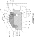
- the retaining ring 100 After the retaining ring 100 is installed into the groove 87, it may rise or pop radially outwardly from the groove 87 relative to the longitudinal axis 11, as shown in FIG. 3B , and abut the protrusions 74. As such, as discussed above, the rotor disc cover plate 36 provides radial retention (with respect to the longitudinal axis 11) to the retaining ring 100 via the protrusions 74 abutting the retaining ring 100. Similarly, as shown in FIG. 3B , the key washer 90 provides axial retention (with respect to the longitudinal axis 11) to the retaining ring 100 via the second axial surface 94 and second portions 97b of the second set of keys 97.
- the radial and axial retention forces are separated or decoupled between two components, illustratively the rotor disc cover plate 36 and the key washer 90.
- Such decoupling may, for instance, allow for a more compact key washer 90 design to avoid interference with various adjacent components such as the carbon seal runner 48.
- various pockets are circumferentially formed to retain or support the retaining ring 100, each pocket formed by one or more protrusions 74, a portion of the second axial surface 94 and one of the second portions 97b of one of the second set of keys 97. As shown in FIG.
- a portion of the retaining ring 100 in an assembled configuration of the retention assembly 50, a portion of the retaining ring 100 remains disposed within the groove 87 while another portion of the retaining ring 100 protrudes radially outwardly of the groove 87.
- the portion of the retaining ring 100 that remains disposed or trapped within the groove 87 is subjected to various axial retention forces from the inner axially-facing portions of the groove 87.
- Such axial retention forces may contribute to the axial retention of the retention ring 100 otherwise provided by the key washer 90.
- the nut 80 is positioned on the rotor disc 24 with the second set of threads 85 engaging with the first set of threads 64.
- the nut 80 is torqued, thus locking or retaining the rotor disc cover plate 36 to the rotor disc 24.
- the key washer 90 is then slipped over the nut 80 and positioned so that the first set of keys 95 engage with the key-receiving slots 86 in the nut 80 to lock the nut 80, i.e. to prevent the nut 80 from unwinding.
- the pliers may be used to narrow or collapse the gap 104 at this stage, causing the retaining ring 100 to sit deeper within the groove 87 so that the key washer 90 can slide over the retaining ring 100.
- the retaining ring 100 may then pop or rise radially outwardly relatively (relative to the longitudinal axis 11) in the groove 87 and abut against the protrusions 74, the protrusions 74 thus radially retaining the retaining ring 100.
- the key washer is concurrently positioned so that the second set of keys 97 are disposed in the cover plate slots 75.
- the retaining ring 100 sits axially and is thus retained between the second axial surface 94 and the second portions 97b of the second set of keys 97 of the key washer 90 relative to the longitudinal axis 11, providing the axial retention of the retention assembly 50.
- the above assembly steps may be carried out in a variety of orders. Other assembly steps may be contemplated as well.
- the illustrated key washer 90 does not make contact with the retaining ring 100 in the radial direction with respect to the longitudinal axis 11 as the retaining ring 100 sits in the groove 87 of the nut 80.
- the retention assembly 50 is dimensioned so that, once assembled, the first portion 97a of the second set of keys 97 of the key washer 90 are positioned radially further from the longitudinal axis than the protrusions 74 which abut the retaining ring 100.
- the retaining ring 100 radially rises or pops radially outwardly within the groove 87, it abuts the protrusions 74, forming a gap 110 between the radially outward surface of the retaining ring 100 and the radially inner surface of the first portion 97a.
- the radial gap 110 is defined by a radial distance between a radially inner surface of the protrusions 74 and a radially inner surface of the first portions 97a of the second set of keys 97.
- the key washer 90 contributes only to the axial retention of the retaining ring 100 and not to the radial retention of the retaining ring 100 relative to the longitudinal axis 11.
- the protrusions 74 contribute only to the radial retention of the retaining retention of the retaining ring 100 and not to the axial retention of the retaining ring 100 relative to the longitudinal axis 11.
- the retention assembly 50 may be suitable to retain rotating components where axial spacing is tight, for instance in the depicted embodiment where the adjacent carbon seal runner 48 limits the axial spacing where the rotor disc cover plate 36 meets the rotor disc 24.
- the compact nature of the retention assembly 50 for instance the lack of overhanging features of the key washer, may render the retention assembly 50 suitable for applications where the rotating components such as the rotor disc 24 spin at high speeds such as 50,000 RPM or higher.
Landscapes
- Engineering & Computer Science (AREA)
- Mechanical Engineering (AREA)
- General Engineering & Computer Science (AREA)
- Turbine Rotor Nozzle Sealing (AREA)
Applications Claiming Priority (2)
| Application Number | Priority Date | Filing Date | Title |
|---|---|---|---|
| US17/209,901 US11414993B1 (en) | 2021-03-23 | 2021-03-23 | Retaining assembly with anti-rotation feature |
| EP22163935.4A EP4063617B1 (de) | 2021-03-23 | 2022-03-23 | Halteanordnung mit verdrehsicherungsfunktion |
Related Parent Applications (1)
| Application Number | Title | Priority Date | Filing Date |
|---|---|---|---|
| EP22163935.4A Division EP4063617B1 (de) | 2021-03-23 | 2022-03-23 | Halteanordnung mit verdrehsicherungsfunktion |
Publications (3)
| Publication Number | Publication Date |
|---|---|
| EP4428341A2 true EP4428341A2 (de) | 2024-09-11 |
| EP4428341A3 EP4428341A3 (de) | 2024-12-18 |
| EP4428341B1 EP4428341B1 (de) | 2026-04-29 |
Family
ID=80930539
Family Applications (2)
| Application Number | Title | Priority Date | Filing Date |
|---|---|---|---|
| EP24187537.6A Active EP4428341B1 (de) | 2021-03-23 | 2022-03-23 | Halteanordnung mit verdrehsicherung |
| EP22163935.4A Active EP4063617B1 (de) | 2021-03-23 | 2022-03-23 | Halteanordnung mit verdrehsicherungsfunktion |
Family Applications After (1)
| Application Number | Title | Priority Date | Filing Date |
|---|---|---|---|
| EP22163935.4A Active EP4063617B1 (de) | 2021-03-23 | 2022-03-23 | Halteanordnung mit verdrehsicherungsfunktion |
Country Status (3)
| Country | Link |
|---|---|
| US (1) | US11414993B1 (de) |
| EP (2) | EP4428341B1 (de) |
| CA (1) | CA3149940A1 (de) |
Families Citing this family (3)
| Publication number | Priority date | Publication date | Assignee | Title |
|---|---|---|---|---|
| FR3150550A1 (fr) * | 2023-06-27 | 2025-01-03 | Safran Aircraft Engines | Dispositif d’accouplement de deux pièces de turbomachine d’aéronef |
| CN119982200B (zh) * | 2023-11-10 | 2026-01-16 | 中国航发商用航空发动机有限责任公司 | 反向螺纹自锁紧组件 |
| US12215766B1 (en) * | 2024-02-22 | 2025-02-04 | Schaeffler Technologies AG & Co. KG | Modular torque converter stator with cammed blades |
Family Cites Families (29)
| Publication number | Priority date | Publication date | Assignee | Title |
|---|---|---|---|---|
| US3222772A (en) * | 1962-10-15 | 1965-12-14 | Gen Motors Corp | Method of mounting a first member nonrotatably and rigidly on a second member |
| US6009609A (en) * | 1998-02-26 | 2000-01-04 | Warn Industries, Inc. | Drive line conversion process |
| TWI220328B (en) * | 2003-06-06 | 2004-08-11 | Delta Electronics Inc | Fastening structure for tandem motor |
| FR2896827B1 (fr) * | 2006-01-27 | 2008-04-25 | Snecma Sa | Assemblage a encombrement radial reduit entre un arbre de turbine et un tourillon d'arbre de compresseur de turbomachine |
| DE102007026040B4 (de) * | 2007-06-04 | 2011-06-16 | Ifa-Technologies Gmbh | Vorrichtung zur Verbindung eines Zapfens eines Getriebes mit einem Gelenkkörper eines Antriebsgelenks einer Antriebswelle |
| GB0818249D0 (en) * | 2008-10-07 | 2008-11-12 | Rolls Royce Plc | Splined couplings |
| US8092312B2 (en) * | 2009-01-29 | 2012-01-10 | American Axle & Manufacturing, Inc. | Multi-piece yoke assembly |
| US8459954B2 (en) * | 2010-01-19 | 2013-06-11 | United Technologies Corporation | Torsional flexing energy absorbing blade lock |
| US8690690B2 (en) * | 2010-06-30 | 2014-04-08 | American Axle & Manufacturing, Inc. | Constant velocity joint with quick connector and method |
| US8579538B2 (en) * | 2010-07-30 | 2013-11-12 | United Technologies Corporation | Turbine engine coupling stack |
| US8491267B2 (en) * | 2010-08-27 | 2013-07-23 | Pratt & Whitney Canada Corp. | Retaining ring arrangement for a rotary assembly |
| ES2606143T3 (es) * | 2010-12-08 | 2017-03-22 | Alcoa Inc. | Conjunto de tuerca de bloqueo |
| US8662845B2 (en) * | 2011-01-11 | 2014-03-04 | United Technologies Corporation | Multi-function heat shield for a gas turbine engine |
| US8840375B2 (en) * | 2011-03-21 | 2014-09-23 | United Technologies Corporation | Component lock for a gas turbine engine |
| US8460118B2 (en) * | 2011-08-31 | 2013-06-11 | United Technologies Corporation | Shaft assembly for a gas turbine engine |
| US8979502B2 (en) * | 2011-12-15 | 2015-03-17 | Pratt & Whitney Canada Corp. | Turbine rotor retaining system |
| US8932022B2 (en) * | 2012-02-03 | 2015-01-13 | Pratt & Whitney Canada Corp. | Fastening system for fan and shaft interconnection |
| US9022684B2 (en) | 2012-02-06 | 2015-05-05 | United Technologies Corporation | Turbine engine shaft coupling |
| JP2013194895A (ja) * | 2012-03-22 | 2013-09-30 | Hitachi Automotive Systems Kyushu Ltd | プロペラシャフト及びこのプロペラシャフトに用いられる等速ジョイント |
| US9212562B2 (en) * | 2012-07-18 | 2015-12-15 | United Technologies Corporation | Bayoneted anti-rotation turbine seals |
| US9297422B2 (en) * | 2012-10-25 | 2016-03-29 | Pratt & Whitney Canada Corp. | Coupling element for torque transmission in a gas turbine engine |
| FR3001505B1 (fr) * | 2013-01-25 | 2015-02-27 | Snecma | Dispositif de blocage axial d'une piece mobile par rapport a une piece de reference |
| US9970321B2 (en) | 2013-12-10 | 2018-05-15 | United Technologies Corporation | Housing support nut connection |
| EP2930303B1 (de) * | 2014-04-10 | 2019-07-24 | United Technologies Corporation | Gasturbinenkupplungsstapel |
| JP6717688B2 (ja) * | 2016-06-30 | 2020-07-01 | 日立オートモティブシステムズ株式会社 | プロペラシャフト |
| JP2018009583A (ja) * | 2016-07-11 | 2018-01-18 | 日立オートモティブシステムズ株式会社 | 動力伝達軸 |
| US10302140B2 (en) * | 2016-12-15 | 2019-05-28 | Pratt & Whitney Canada Corp. | Spline alignment |
| US11434958B2 (en) * | 2017-05-03 | 2022-09-06 | Neapco Intellectual Property Holdings, Llc | High retention force serviceable plug-on joint assembly |
| US11105204B2 (en) * | 2019-06-11 | 2021-08-31 | Pratt & Whitney Canada Corp. | Turbine assembly |
-
2021
- 2021-03-23 US US17/209,901 patent/US11414993B1/en active Active
-
2022
- 2022-02-23 CA CA3149940A patent/CA3149940A1/en active Pending
- 2022-03-23 EP EP24187537.6A patent/EP4428341B1/de active Active
- 2022-03-23 EP EP22163935.4A patent/EP4063617B1/de active Active
Also Published As
| Publication number | Publication date |
|---|---|
| EP4428341A3 (de) | 2024-12-18 |
| US11414993B1 (en) | 2022-08-16 |
| EP4063617B1 (de) | 2024-07-10 |
| CA3149940A1 (en) | 2022-09-23 |
| EP4063617A1 (de) | 2022-09-28 |
| EP4428341B1 (de) | 2026-04-29 |
Similar Documents
| Publication | Publication Date | Title |
|---|---|---|
| EP4428341A2 (de) | Halteanordnung mit verdrehsicherung | |
| JP5788492B2 (ja) | タービンエンジン用アンダクテッドファン | |
| US5052891A (en) | Connection for gas turbine engine rotor elements | |
| US9371863B2 (en) | Turbine engine coupling stack | |
| US8506253B2 (en) | Balancing apparatus for rotor assembly | |
| CA2677372C (en) | Combustor liner with integrated anti-rotation and removal feature | |
| RU2436965C2 (ru) | Устройство для крепления направляющего соплового аппарата турбины, турбина и двигатель самолета с таким оборудованием | |
| EP3751096B1 (de) | Turbinenanordnung | |
| EP3246517B1 (de) | Befestigungselementöffnungen zur spannungsverteilung | |
| CA2935993C (en) | Spoke locking architecture | |
| US7530791B2 (en) | Turbine blade retaining apparatus | |
| US10975707B2 (en) | Turbomachine disc cover mounting arrangement | |
| EP3825520B1 (de) | Anordnung mit leitschaufel und dichtungselement für ein gasturbinentriebwerk | |
| EP3219931B1 (de) | Leitschaufelanordnung und zugehöriger gasturbinenmotor | |
| US6773228B2 (en) | Methods and apparatus for turbine nozzle locks | |
| EP4174329B1 (de) | Verriegelungslaschenwascher | |
| EP3647540B1 (de) | Turbinenrotorverriegelungsanordnung und -verfahren | |
| EP3730737B1 (de) | Rotorkupplungsring | |
| US20200263780A1 (en) | Device, planetary gear with a device and method for creating a torque-proof connection between two structural components |
Legal Events
| Date | Code | Title | Description |
|---|---|---|---|
| PUAI | Public reference made under article 153(3) epc to a published international application that has entered the european phase |
Free format text: ORIGINAL CODE: 0009012 |
|
| STAA | Information on the status of an ep patent application or granted ep patent |
Free format text: STATUS: THE APPLICATION HAS BEEN PUBLISHED |
|
| AC | Divisional application: reference to earlier application |
Ref document number: 4063617 Country of ref document: EP Kind code of ref document: P |
|
| AK | Designated contracting states |
Kind code of ref document: A2 Designated state(s): AL AT BE BG CH CY CZ DE DK EE ES FI FR GB GR HR HU IE IS IT LI LT LU LV MC MK MT NL NO PL PT RO RS SE SI SK SM TR |
|
| REG | Reference to a national code |
Ref country code: DE Free format text: PREVIOUS MAIN CLASS: F01D0005300000 Ipc: F01D0005020000 Ref country code: DE Ref legal event code: R079 Ref document number: 602022035950 Country of ref document: DE Free format text: PREVIOUS MAIN CLASS: F01D0005300000 Ipc: F01D0005020000 |
|
| PUAL | Search report despatched |
Free format text: ORIGINAL CODE: 0009013 |
|
| AK | Designated contracting states |
Kind code of ref document: A3 Designated state(s): AL AT BE BG CH CY CZ DE DK EE ES FI FR GB GR HR HU IE IS IT LI LT LU LV MC MK MT NL NO PL PT RO RS SE SI SK SM TR |
|
| RIC1 | Information provided on ipc code assigned before grant |
Ipc: F01D 5/30 20060101ALI20241112BHEP Ipc: F01D 5/02 20060101AFI20241112BHEP |
|
| STAA | Information on the status of an ep patent application or granted ep patent |
Free format text: STATUS: REQUEST FOR EXAMINATION WAS MADE |
|
| 17P | Request for examination filed |
Effective date: 20250403 |
|
| RIC1 | Information provided on ipc code assigned before grant |
Ipc: F01D 5/02 20060101AFI20250820BHEP Ipc: F01D 5/30 20060101ALI20250820BHEP |
|
| GRAP | Despatch of communication of intention to grant a patent |
Free format text: ORIGINAL CODE: EPIDOSNIGR1 |
|
| STAA | Information on the status of an ep patent application or granted ep patent |
Free format text: STATUS: GRANT OF PATENT IS INTENDED |
|
| INTG | Intention to grant announced |
Effective date: 20251017 |
|
| GRAS | Grant fee paid |
Free format text: ORIGINAL CODE: EPIDOSNIGR3 |
|
| GRAA | (expected) grant |
Free format text: ORIGINAL CODE: 0009210 |
|
| STAA | Information on the status of an ep patent application or granted ep patent |
Free format text: STATUS: THE PATENT HAS BEEN GRANTED |
|
| AC | Divisional application: reference to earlier application |
Ref document number: 4063617 Country of ref document: EP Kind code of ref document: P |
|
| AK | Designated contracting states |
Kind code of ref document: B1 Designated state(s): AL AT BE BG CH CY CZ DE DK EE ES FI FR GB GR HR HU IE IS IT LI LT LU LV MC MK MT NL NO PL PT RO RS SE SI SK SM TR |
|
| REG | Reference to a national code |
Ref country code: CH Ref legal event code: F10 Free format text: ST27 STATUS EVENT CODE: U-0-0-F10-F00 (AS PROVIDED BY THE NATIONAL OFFICE) Effective date: 20260429 |