EP3753994B1 - Composant luminescent - Google Patents
Composant luminescent Download PDFInfo
- Publication number
- EP3753994B1 EP3753994B1 EP19180680.1A EP19180680A EP3753994B1 EP 3753994 B1 EP3753994 B1 EP 3753994B1 EP 19180680 A EP19180680 A EP 19180680A EP 3753994 B1 EP3753994 B1 EP 3753994B1
- Authority
- EP
- European Patent Office
- Prior art keywords
- polymer
- luminescent
- polymer composition
- optionally
- liquid
- Prior art date
- Legal status (The legal status is an assumption and is not a legal conclusion. Google has not performed a legal analysis and makes no representation as to the accuracy of the status listed.)
- Active
Links
Images

Classifications
-
- C—CHEMISTRY; METALLURGY
- C09—DYES; PAINTS; POLISHES; NATURAL RESINS; ADHESIVES; COMPOSITIONS NOT OTHERWISE PROVIDED FOR; APPLICATIONS OF MATERIALS NOT OTHERWISE PROVIDED FOR
- C09K—MATERIALS FOR MISCELLANEOUS APPLICATIONS, NOT PROVIDED FOR ELSEWHERE
- C09K11/00—Luminescent materials, e.g. electroluminescent or chemiluminescent
- C09K11/02—Use of particular materials as binders, particle coatings or suspension media therefor
-
- C—CHEMISTRY; METALLURGY
- C01—INORGANIC CHEMISTRY
- C01D—COMPOUNDS OF ALKALI METALS, i.e. LITHIUM, SODIUM, POTASSIUM, RUBIDIUM, CAESIUM, OR FRANCIUM
- C01D13/00—Compounds of sodium or potassium not provided for elsewhere
-
- C—CHEMISTRY; METALLURGY
- C01—INORGANIC CHEMISTRY
- C01D—COMPOUNDS OF ALKALI METALS, i.e. LITHIUM, SODIUM, POTASSIUM, RUBIDIUM, CAESIUM, OR FRANCIUM
- C01D15/00—Lithium compounds
-
- C—CHEMISTRY; METALLURGY
- C01—INORGANIC CHEMISTRY
- C01D—COMPOUNDS OF ALKALI METALS, i.e. LITHIUM, SODIUM, POTASSIUM, RUBIDIUM, CAESIUM, OR FRANCIUM
- C01D17/00—Rubidium, caesium or francium compounds
- C01D17/003—Compounds of alkali metals
-
- C—CHEMISTRY; METALLURGY
- C01—INORGANIC CHEMISTRY
- C01G—COMPOUNDS CONTAINING METALS NOT COVERED BY SUBCLASSES C01D OR C01F
- C01G17/00—Compounds of germanium
-
- C—CHEMISTRY; METALLURGY
- C01—INORGANIC CHEMISTRY
- C01G—COMPOUNDS CONTAINING METALS NOT COVERED BY SUBCLASSES C01D OR C01F
- C01G19/00—Compounds of tin
-
- C—CHEMISTRY; METALLURGY
- C01—INORGANIC CHEMISTRY
- C01G—COMPOUNDS CONTAINING METALS NOT COVERED BY SUBCLASSES C01D OR C01F
- C01G21/00—Compounds of lead
-
- C—CHEMISTRY; METALLURGY
- C01—INORGANIC CHEMISTRY
- C01G—COMPOUNDS CONTAINING METALS NOT COVERED BY SUBCLASSES C01D OR C01F
- C01G29/00—Compounds of bismuth
-
- C—CHEMISTRY; METALLURGY
- C01—INORGANIC CHEMISTRY
- C01G—COMPOUNDS CONTAINING METALS NOT COVERED BY SUBCLASSES C01D OR C01F
- C01G30/00—Compounds of antimony
-
- C—CHEMISTRY; METALLURGY
- C09—DYES; PAINTS; POLISHES; NATURAL RESINS; ADHESIVES; COMPOSITIONS NOT OTHERWISE PROVIDED FOR; APPLICATIONS OF MATERIALS NOT OTHERWISE PROVIDED FOR
- C09D—COATING COMPOSITIONS, e.g. PAINTS, VARNISHES OR LACQUERS; FILLING PASTES; CHEMICAL PAINT OR INK REMOVERS; INKS; CORRECTING FLUIDS; WOODSTAINS; PASTES OR SOLIDS FOR COLOURING OR PRINTING; USE OF MATERIALS THEREFOR
- C09D11/00—Inks
- C09D11/50—Sympathetic, colour changing or similar inks
-
- C—CHEMISTRY; METALLURGY
- C09—DYES; PAINTS; POLISHES; NATURAL RESINS; ADHESIVES; COMPOSITIONS NOT OTHERWISE PROVIDED FOR; APPLICATIONS OF MATERIALS NOT OTHERWISE PROVIDED FOR
- C09D—COATING COMPOSITIONS, e.g. PAINTS, VARNISHES OR LACQUERS; FILLING PASTES; CHEMICAL PAINT OR INK REMOVERS; INKS; CORRECTING FLUIDS; WOODSTAINS; PASTES OR SOLIDS FOR COLOURING OR PRINTING; USE OF MATERIALS THEREFOR
- C09D5/00—Coating compositions, e.g. paints, varnishes or lacquers, characterised by their physical nature or the effects produced; Filling pastes
- C09D5/22—Luminous paints
-
- C—CHEMISTRY; METALLURGY
- C09—DYES; PAINTS; POLISHES; NATURAL RESINS; ADHESIVES; COMPOSITIONS NOT OTHERWISE PROVIDED FOR; APPLICATIONS OF MATERIALS NOT OTHERWISE PROVIDED FOR
- C09K—MATERIALS FOR MISCELLANEOUS APPLICATIONS, NOT PROVIDED FOR ELSEWHERE
- C09K11/00—Luminescent materials, e.g. electroluminescent or chemiluminescent
- C09K11/02—Use of particular materials as binders, particle coatings or suspension media therefor
- C09K11/025—Use of particular materials as binders, particle coatings or suspension media therefor non-luminescent particle coatings or suspension media
-
- C—CHEMISTRY; METALLURGY
- C09—DYES; PAINTS; POLISHES; NATURAL RESINS; ADHESIVES; COMPOSITIONS NOT OTHERWISE PROVIDED FOR; APPLICATIONS OF MATERIALS NOT OTHERWISE PROVIDED FOR
- C09K—MATERIALS FOR MISCELLANEOUS APPLICATIONS, NOT PROVIDED FOR ELSEWHERE
- C09K11/00—Luminescent materials, e.g. electroluminescent or chemiluminescent
- C09K11/06—Luminescent materials, e.g. electroluminescent or chemiluminescent containing organic luminescent materials
-
- C—CHEMISTRY; METALLURGY
- C09—DYES; PAINTS; POLISHES; NATURAL RESINS; ADHESIVES; COMPOSITIONS NOT OTHERWISE PROVIDED FOR; APPLICATIONS OF MATERIALS NOT OTHERWISE PROVIDED FOR
- C09K—MATERIALS FOR MISCELLANEOUS APPLICATIONS, NOT PROVIDED FOR ELSEWHERE
- C09K11/00—Luminescent materials, e.g. electroluminescent or chemiluminescent
- C09K11/08—Luminescent materials, e.g. electroluminescent or chemiluminescent containing inorganic luminescent materials
- C09K11/66—Luminescent materials, e.g. electroluminescent or chemiluminescent containing inorganic luminescent materials containing germanium, tin or lead
- C09K11/664—Halogenides
-
- F—MECHANICAL ENGINEERING; LIGHTING; HEATING; WEAPONS; BLASTING
- F21—LIGHTING
- F21V—FUNCTIONAL FEATURES OR DETAILS OF LIGHTING DEVICES OR SYSTEMS THEREOF; STRUCTURAL COMBINATIONS OF LIGHTING DEVICES WITH OTHER ARTICLES, NOT OTHERWISE PROVIDED FOR
- F21V3/00—Globes; Bowls; Cover glasses
- F21V3/04—Globes; Bowls; Cover glasses characterised by materials, surface treatments or coatings
- F21V3/10—Globes; Bowls; Cover glasses characterised by materials, surface treatments or coatings characterised by coatings
- F21V3/12—Globes; Bowls; Cover glasses characterised by materials, surface treatments or coatings characterised by coatings the coatings comprising photoluminescent substances
-
- F—MECHANICAL ENGINEERING; LIGHTING; HEATING; WEAPONS; BLASTING
- F21—LIGHTING
- F21V—FUNCTIONAL FEATURES OR DETAILS OF LIGHTING DEVICES OR SYSTEMS THEREOF; STRUCTURAL COMBINATIONS OF LIGHTING DEVICES WITH OTHER ARTICLES, NOT OTHERWISE PROVIDED FOR
- F21V9/00—Elements for modifying spectral properties, polarisation or intensity of the light emitted, e.g. filters
- F21V9/30—Elements containing photoluminescent material distinct from or spaced from the light source
- F21V9/38—Combination of two or more photoluminescent elements of different materials
-
- G—PHYSICS
- G02—OPTICS
- G02F—OPTICAL DEVICES OR ARRANGEMENTS FOR THE CONTROL OF LIGHT BY MODIFICATION OF THE OPTICAL PROPERTIES OF THE MEDIA OF THE ELEMENTS INVOLVED THEREIN; NON-LINEAR OPTICS; FREQUENCY-CHANGING OF LIGHT; OPTICAL LOGIC ELEMENTS; OPTICAL ANALOGUE/DIGITAL CONVERTERS
- G02F1/00—Devices or arrangements for the control of the intensity, colour, phase, polarisation or direction of light arriving from an independent light source, e.g. switching, gating or modulating; Non-linear optics
- G02F1/01—Devices or arrangements for the control of the intensity, colour, phase, polarisation or direction of light arriving from an independent light source, e.g. switching, gating or modulating; Non-linear optics for the control of the intensity, phase, polarisation or colour
- G02F1/13—Devices or arrangements for the control of the intensity, colour, phase, polarisation or direction of light arriving from an independent light source, e.g. switching, gating or modulating; Non-linear optics for the control of the intensity, phase, polarisation or colour based on liquid crystals, e.g. single liquid crystal display cells
- G02F1/133—Constructional arrangements; Operation of liquid crystal cells; Circuit arrangements
- G02F1/1333—Constructional arrangements; Manufacturing methods
- G02F1/1335—Structural association of cells with optical devices, e.g. polarisers or reflectors
- G02F1/1336—Illuminating devices
- G02F1/133614—Illuminating devices using photoluminescence, e.g. phosphors illuminated by UV or blue light
-
- G—PHYSICS
- G02—OPTICS
- G02F—OPTICAL DEVICES OR ARRANGEMENTS FOR THE CONTROL OF LIGHT BY MODIFICATION OF THE OPTICAL PROPERTIES OF THE MEDIA OF THE ELEMENTS INVOLVED THEREIN; NON-LINEAR OPTICS; FREQUENCY-CHANGING OF LIGHT; OPTICAL LOGIC ELEMENTS; OPTICAL ANALOGUE/DIGITAL CONVERTERS
- G02F1/00—Devices or arrangements for the control of the intensity, colour, phase, polarisation or direction of light arriving from an independent light source, e.g. switching, gating or modulating; Non-linear optics
- G02F1/01—Devices or arrangements for the control of the intensity, colour, phase, polarisation or direction of light arriving from an independent light source, e.g. switching, gating or modulating; Non-linear optics for the control of the intensity, phase, polarisation or colour
- G02F1/13—Devices or arrangements for the control of the intensity, colour, phase, polarisation or direction of light arriving from an independent light source, e.g. switching, gating or modulating; Non-linear optics for the control of the intensity, phase, polarisation or colour based on liquid crystals, e.g. single liquid crystal display cells
- G02F1/133—Constructional arrangements; Operation of liquid crystal cells; Circuit arrangements
- G02F1/1333—Constructional arrangements; Manufacturing methods
- G02F1/1335—Structural association of cells with optical devices, e.g. polarisers or reflectors
- G02F1/1336—Illuminating devices
- G02F1/133617—Illumination with ultraviolet light; Luminescent elements or materials associated to the cell
-
- H—ELECTRICITY
- H10—SEMICONDUCTOR DEVICES; ELECTRIC SOLID-STATE DEVICES NOT OTHERWISE PROVIDED FOR
- H10H—INORGANIC LIGHT-EMITTING SEMICONDUCTOR DEVICES HAVING POTENTIAL BARRIERS
- H10H20/00—Individual inorganic light-emitting semiconductor devices having potential barriers, e.g. light-emitting diodes [LED]
- H10H20/80—Constructional details
- H10H20/85—Packages
- H10H20/851—Wavelength conversion means
- H10H20/8511—Wavelength conversion means characterised by their material, e.g. binder
- H10H20/8512—Wavelength conversion materials
-
- H—ELECTRICITY
- H10—SEMICONDUCTOR DEVICES; ELECTRIC SOLID-STATE DEVICES NOT OTHERWISE PROVIDED FOR
- H10H—INORGANIC LIGHT-EMITTING SEMICONDUCTOR DEVICES HAVING POTENTIAL BARRIERS
- H10H20/00—Individual inorganic light-emitting semiconductor devices having potential barriers, e.g. light-emitting diodes [LED]
- H10H20/80—Constructional details
- H10H20/85—Packages
- H10H20/852—Encapsulations
- H10H20/854—Encapsulations characterised by their material, e.g. epoxy or silicone resins
-
- H—ELECTRICITY
- H10—SEMICONDUCTOR DEVICES; ELECTRIC SOLID-STATE DEVICES NOT OTHERWISE PROVIDED FOR
- H10K—ORGANIC ELECTRIC SOLID-STATE DEVICES
- H10K30/00—Organic devices sensitive to infrared radiation, light, electromagnetic radiation of shorter wavelength or corpuscular radiation
- H10K30/10—Organic devices sensitive to infrared radiation, light, electromagnetic radiation of shorter wavelength or corpuscular radiation comprising heterojunctions between organic semiconductors and inorganic semiconductors
-
- H—ELECTRICITY
- H10—SEMICONDUCTOR DEVICES; ELECTRIC SOLID-STATE DEVICES NOT OTHERWISE PROVIDED FOR
- H10K—ORGANIC ELECTRIC SOLID-STATE DEVICES
- H10K50/00—Organic light-emitting devices
- H10K50/10—OLEDs or polymer light-emitting diodes [PLED]
- H10K50/11—OLEDs or polymer light-emitting diodes [PLED] characterised by the electroluminescent [EL] layers
-
- H—ELECTRICITY
- H10—SEMICONDUCTOR DEVICES; ELECTRIC SOLID-STATE DEVICES NOT OTHERWISE PROVIDED FOR
- H10K—ORGANIC ELECTRIC SOLID-STATE DEVICES
- H10K50/00—Organic light-emitting devices
- H10K50/10—OLEDs or polymer light-emitting diodes [PLED]
- H10K50/11—OLEDs or polymer light-emitting diodes [PLED] characterised by the electroluminescent [EL] layers
- H10K50/115—OLEDs or polymer light-emitting diodes [PLED] characterised by the electroluminescent [EL] layers comprising active inorganic nanostructures, e.g. luminescent quantum dots
-
- H—ELECTRICITY
- H10—SEMICONDUCTOR DEVICES; ELECTRIC SOLID-STATE DEVICES NOT OTHERWISE PROVIDED FOR
- H10K—ORGANIC ELECTRIC SOLID-STATE DEVICES
- H10K50/00—Organic light-emitting devices
- H10K50/10—OLEDs or polymer light-emitting diodes [PLED]
- H10K50/11—OLEDs or polymer light-emitting diodes [PLED] characterised by the electroluminescent [EL] layers
- H10K50/125—OLEDs or polymer light-emitting diodes [PLED] characterised by the electroluminescent [EL] layers specially adapted for multicolour light emission, e.g. for emitting white light
-
- H—ELECTRICITY
- H10—SEMICONDUCTOR DEVICES; ELECTRIC SOLID-STATE DEVICES NOT OTHERWISE PROVIDED FOR
- H10K—ORGANIC ELECTRIC SOLID-STATE DEVICES
- H10K50/00—Organic light-emitting devices
- H10K50/10—OLEDs or polymer light-emitting diodes [PLED]
- H10K50/11—OLEDs or polymer light-emitting diodes [PLED] characterised by the electroluminescent [EL] layers
- H10K50/125—OLEDs or polymer light-emitting diodes [PLED] characterised by the electroluminescent [EL] layers specially adapted for multicolour light emission, e.g. for emitting white light
- H10K50/13—OLEDs or polymer light-emitting diodes [PLED] characterised by the electroluminescent [EL] layers specially adapted for multicolour light emission, e.g. for emitting white light comprising stacked EL layers within one EL unit
-
- H—ELECTRICITY
- H10—SEMICONDUCTOR DEVICES; ELECTRIC SOLID-STATE DEVICES NOT OTHERWISE PROVIDED FOR
- H10K—ORGANIC ELECTRIC SOLID-STATE DEVICES
- H10K85/00—Organic materials used in the body or electrodes of devices covered by this subclass
-
- H—ELECTRICITY
- H10—SEMICONDUCTOR DEVICES; ELECTRIC SOLID-STATE DEVICES NOT OTHERWISE PROVIDED FOR
- H10H—INORGANIC LIGHT-EMITTING SEMICONDUCTOR DEVICES HAVING POTENTIAL BARRIERS
- H10H20/00—Individual inorganic light-emitting semiconductor devices having potential barriers, e.g. light-emitting diodes [LED]
- H10H20/01—Manufacture or treatment
- H10H20/036—Manufacture or treatment of packages
- H10H20/0361—Manufacture or treatment of packages of wavelength conversion means
-
- Y—GENERAL TAGGING OF NEW TECHNOLOGICAL DEVELOPMENTS; GENERAL TAGGING OF CROSS-SECTIONAL TECHNOLOGIES SPANNING OVER SEVERAL SECTIONS OF THE IPC; TECHNICAL SUBJECTS COVERED BY FORMER USPC CROSS-REFERENCE ART COLLECTIONS [XRACs] AND DIGESTS
- Y02—TECHNOLOGIES OR APPLICATIONS FOR MITIGATION OR ADAPTATION AGAINST CLIMATE CHANGE
- Y02P—CLIMATE CHANGE MITIGATION TECHNOLOGIES IN THE PRODUCTION OR PROCESSING OF GOODS
- Y02P70/00—Climate change mitigation technologies in the production process for final industrial or consumer products
- Y02P70/50—Manufacturing or production processes characterised by the final manufactured product
Definitions
- the present invention relates to the field of luminescent crystals (LCs), components and devices comprising the same.
- the invention provides a luminescent component, light emitting devices comprising such components, the use of a luminescent component, the use of specific polymers in such components and methods for manufacturing luminescent components and light emitting devices.
- WO2011/053635 discloses light-emitting diode (LED) devices comprising compositions and containers of hermetically sealed nano-sized luminescent crystals ("LCs").
- LED light-emitting diode
- WO2017/106979 discloses luminescent components comprising luminescent crystals in a first polymer and encapsulated in a polymer or inorganic matrix.
- WO2018/028869 discloses luminescent materials from the class of perovskite crystals and the manufacturing thereof.
- US20180298278 discloses a composite luminescent material comprising perovskite nanoparticles dispersed in a specific matrix.
- the document aims to improve drawbacks of known composite luminescent materials, such as low Quantum Yield and low stability and suggests overcoming them by improved manufacturing methods. Although suitable, the manufacturing methods disclosed are difficult to implement on a commercial scale and Quantum Yield and Stability are still considered insufficient.
- US2018273841 discloses a luminescent component, comprising a first film comprising a first solid polymer composition, wherein the first solid polymer composition comprises first luminescent crystals, wherein the first luminescent crystals are of the perovskite structure, a second film comprising a second solid polymer composition wherein the second solid polymer composition comprises second luminescent crystals, wherein the second luminescent crystals are of the perovskite structure and one or more barrier films.
- Known luminescent components may comprise barrier films to improve stability against oxygen or humidity. Although suitable for many applications, it was found that these luminescent components and lighting devices lack stability, particularly in view of high temperature and high humidity and blue light radiation.
- LC luminescent crystal
- the term "luminescent crystal” is known in the field and relates to crystals of 3-100 nm, made of semiconductor materials.
- the term comprises quantum dots, typically in the range of 3 - 15 nm and nanocrystals, typically in the range of more than 15 nm and up to 100 nm (preferably up to 50 nm).
- luminescent crystals are approximately isometric (such as spherical or cubic). Particles are considered approximately isometric, in case the aspect ratio (longest : shortest direction) of all 3 orthogonal dimensions is 1 - 2.
- an assembly of LCs preferably contains 50 - 100 % (n/n), preferably 66 - 100 % (n/n) much preferably 75 - 100 % (n/n) isometric nanocrystals.
- LCs show, as the term indicates, luminescence.
- the term luminescent crystal includes both, single crystals and polycrystalline particles. In the latter case, one particle may be composed of several crystal domains (grains), connected by crystalline or amorphous phase boundaries.
- a luminescent crystal is a semiconducting material which exhibits a direct bandgap (typically in the range 1.1 - 3.8 eV, more typically 1.4 - 3.5 eV, even more typically 1.7 - 3.2 eV).
- the valence band electron Upon illumination with electromagnetic radiation equal or higher than the bandgap, the valence band electron is excited to the conduction band leaving an electron hole in the valence band.
- the formed exciton (electron-electron hole pair) then radiatively recombines in the form of photoluminescence, with maximum intensity centered around the LC bandgap value and exhibiting photoluminescence quantum yield of at least 1 %.
- LC could exhibit electroluminescence.
- LCs do not exhibit mechanoluminescence (e.g. piezoluminescence), chemiluminescence, electrochemi-luminescence nor thermoluminescence.
- QD quantum dot
- the term "quantum dot” is known and particularly relates to semiconductor nanocrystals, which have a diameter typically between 3 - 15 nm. In this range, the physical radius of the QD is smaller than the bulk excitation Bohr radius, causing quantum confinement effect to predominate.
- the electronic states of the QD, and therefore the bandgap are a function of the QD composition and physical size, i.e. the color of absorption/emission is linked with the QD size.
- the optical quality of the QDs sample is directly linked with their homogeneity (more monodisperse QDs will have smaller FWHM of the emission).
- QDs are a specific sub-group of nanocrystals, defined in particular by its size and size distribution.
- perovskite crystals is known and particularly includes crystalline compounds of the perovskite structure.
- perovskite structures are known per se and described as cubic, pseudocubic, tetragonal or orthorhombic crystals of general formula M 1 M 2 X 3 , where M 1 are cations of coordination number 12 (cuboctaeder) and M 2 are cations of coordination number 6 (octaeder) and X are anions in cubic, pseudocubic, tetragonal or orthorhombic positions of the lattice.
- selected cations or anions may be replaced by other ions (stochastic or regularly up to 30 atom-%), thereby resulting in doped perovskites or non-stochiometric perovskites, still maintaining its original crystalline structure.
- the manufacturing of such luminescent crystals is known, e.g. from WO2018 028869 .
- polymer is known and includes organic and inorganic synthetic materials comprising repeating units ("monomers").
- the term polymers includes homo-polymers and co-polymers. Further, cross-linked polymers and non-cross-linked polymers are included. Depending on the context, the term polymer shall include its monomers and oligomers.
- Polymers include, by way of example, acrylate polymers, carbonate polymers, sulfone polymers, epoxy polymers, vinyl polymers, urethane polymers, imide polymers, ester polymers, furane polymers, melamine polymers, styrene polymers, norbornene polymers, silicone polymers and cyclic olefin copolymers.
- Polymers may include, as conventional in the field, other materials such as polymerization initiators, stabilizers, fillers, solvents. Polymers may be further characterized by physical parameters, such as polarity, glass transition temperature Tg, Young's modulus and light transmittance. Transmittance: Typically, polymers used in the context of this invention are light transmissive for visible light, i.e. non-opaque for allowing light emitted by the luminescent crystals, and possible light of a light source used for exciting the luminescent crystals to pass. Light transmittance may be determinded by white light interferometry or UV-Vis spectrometry.
- Tg Glass transition temperature
- Polymers with high Tg are considered “hard”, while polymers with low Tg are considered “soft”.
- Tg is not a discrete thermodynamic transition, but a temperature range over which the mobility of the polymer chains increase significantly. The convention, however, is to report a single temperature defined as the midpoint of the temperature range, bounded by the tangents to the two flat regions of the heat flow curve of the DSC measurement.
- Tg may be determined according to DIN EN ISO 11357-2 or ASTM E1356 using DSC. This method is particularly suitable if the polymer is present in the form of bulk material. Alternatively, Tg may be determined by measuring temperature-dependent micro- or nanohardness with micro- or nanoindentation accordinging to ISO 14577-1 or ASTM E2546-15. This method is suited for luminescent components and lighting devices as disclosed herein. Suitable analytical equipment is available as MHT (Anton Paar), Hy-sitron TI Premier (Bruker) or Nano Indenter G200 (Keysight Technologies). Data obtained by temperature controlled micro- and nanoindentation can be converted to Tg.
- Young's modulus or Young modulus or Elasticity modulus is a mechanical property that measures the stiffness of a solid material. It defines the relationship between stress (force per unit area) and strain (proportional deformation) in a material in the linear elasticity regime of a uniaxial deformation.
- matrix is known in the field and in the context of this invention denotes continuous phase encompassing a discontinuous or particulate phase. The continuous material thereby encapsulating the particulate phase.
- solvent is known in the field and particularly includes aliphatic hydrocarbons, aromatic hydrocarbons, ethers (including glycol-ethers), esters, alcohols, ketones, amines, amides, sulfones, phosphines, alkylcarbonates.
- the above organics can be substituted or unsubstituted by one or more substituents, for example by halogen (such as fluoro, chloro, iodo or bromo), Hydroxy, C1-4 alkoxy (such as methoxy or ethoxy) and alkyl (such as methyl, ethyl, isopropyl).
- the above organics include linear, branched and cyclic derivatives. There can also be unsaturated bonds in the molecule.
- the above compounds typically have 4 - 24 carbon atoms, preferably 8 - 22 carbon atoms, most preferably 12-20 carbon atoms.
- surfactant ligand
- dispersant dispersing agent
- these terms denote an organic substance, other than a solvent, which is used in suspensions or colloids to improve the separation of particles and to prevent agglomeration or settling.
- surfactants are physically or chemically attached on the particle surface either before or after adding the particles to the solvent and thereby provide the desired effects.
- surfactants includes polymer materials and small molecules; surfactants typically contain polar functional end-groups and apolar end-groups.
- solvents e.g. toluene are not considered surfactants.
- the term "suspension” is known and relates to a heterogeneous fluid of an internal phase (i.p.) that is a solid and an external phase (e.p.) that is a liquid.
- the external phase comprises one or more dispersants/surfactants, optionally one or more solvents and optionally one or more pre-polymers.
- solution processing relates to the fabrication of commercial products, such as electronic devices, optical devices, and articles comprising (decorative) coatings and also to the fabrication of components / intermediate goods comprising a LC composite or LC layer.
- the application of the suspension(s) is/are conducted at ambient conditions.
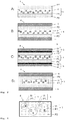
- a luminescent component 4 comprises a first element 1 including first luminescent crystals 11 from the class of perovskite crystals, embedded a first polymer P1 and a second element 2 comprising a second solid polymer composition, said second polymer composition optionally comprising second luminescent crystals 12 embedded in a second polymer P2.
- P1 and P2 differ.
- the invention provides a luminescent component 4 comprising a 1st element 1 and a 2nd element 2.
- Said first element 1 comprises a first solid polymer composition, said first polymer composition comprising first luminescent crystals 11 embedded in a first polymer P1.
- Said first luminescent crystals are of the perovskite crystal structure and emit light of a first wavelength in response to excitation by light with a wavelength shorter than the first wavelength.
- Said first polymer P1 is selected from the group of polymers with T g ⁇ 95°C (preferably ⁇ 90°C, preferably ⁇ 80°C, most preferably ⁇ 70°C).
- Said second element 2 comprises a second solid polymer composition optionally comprising second luminescent crystals 12 embedded in a second polymer P2.
- Said optional second luminescent crystals 12 are different from said first luminescent crystals 11 and emit light of a second wavelength in response to excitation by light with a wavelength shorter than the second wavelength.
- Said second polymer P2 is selected from the group of crosslinked polymers with T g > 115°C (preferably > 120°C, preferably > 130°C, preferably > 140°C, most preferably > 150°C). The second element at least partially covers and thereby seals the first element.
- Each Tg is determined by DSC according to DIN EN ISO 11357-2:2014-07 with a starting temperature of -90°C and an end temperature of 250°C and a heating rate of 20 K/min in nitrogen (5.0) atmosphere (20 ml/min).
- the purging gas is nitrogen (5.0) at 20 ml/min.
- the T g is determined during the second heating cycle.
- the invention provides a luminescent component 4 comprising a 1st element 1 and a 2nd element 2.
- Said first element 1 comprises a first solid polymer composition, said first polymer composition comprising first luminescent crystals 11 embedded in a first polymer P1.
- Said first luminescent crystals are of the perovskite crystal structure and emit light of a first wavelength in response to excitation by light with a wavelength shorter than the first wavelength.
- Said first polymer P1 is selected from the group of polymers with T g ⁇ 95°C (preferably ⁇ 90°C, preferably ⁇ 80°C, most preferably ⁇ 70°C).
- Said second element 2 comprises a second solid polymer composition optionally comprising second luminescent crystals 12 embedded in a second polymer P2.
- Said optional second luminescent crystals 12 are different from said first luminescent crystals 11 and emit light of a second wavelength in response to excitation by light with a wavelength shorter than the second wavelength.
- Said second polymer P2 is selected from the group of polymers with WVTR ⁇ 1 (g*mm)/(m2*day) (preferably ⁇ 0.5, more preferably ⁇ 0.2 (g*mm)/(m2*day)).
- the second element at least partially covers and thereby seals the first element.
- P2 is preferably not a crosslinked polymer.
- Each Tg is determined by DSC according to DIN EN ISO 11357-2:2014-07 with a starting temperature of -90°C and an end temperature of 250°C and a heating rate of 20 K/min in nitrogen (5.0) atmosphere (20 ml/min).
- the purging gas is nitrogen (5.0) at 20 ml/min.
- the T g is determined during the second heating cycle.
- Each WVTR is determined by ISO 15106-3:2003 at a temperature/relative humidity of 40°C /90%r.h.
- the first element does not spontaneously emit light of a wavelength but does so in response to an excitation, and in particular in response to an excitation with light of a wavelength shorter than the wavelength of the light to be emitted in response to the excitation.
- the first element emits light of a first wavelength, e.g. light in the green spectrum in response to an excitation with e.g. light in the blue spectrum.
- the second element may or may not comprise luminescent crystals.
- the second element does not spontaneously emit light of a wavelength but does so in response to an excitation, and in particular in response to an excitation with light of a wavelength shorter than the wavelength of the light to be emitted in response to the excitation.
- the second element emits light of a second wavelength, e.g. light in the red spectrum in response to an excitation with e.g. light in the blue spectrum.
- first and P2 do not dissolve with each other when in contact, at least when in contact in the solid phase at room temperature.
- first and second element remain as distinct phases with one or more phase boundaries within the luminescent component 4.
- the first element and the second element thus possess individual surfaces.
- luminescent component simultaneously shows good stability towards light radiation (especially blue light radiation) and good stability towards temperature and humidity. This is considered a significant improvement over the prior art.
- Known luminescent components show good stability towards light radiation but fail in view of stability towards temperature and humidity.
- luminescent components are known that show good stability towards temperature and humidity but fail in view of stability towards light radiation. Meeting both criteria for stability, i.e. photo stability on the one side and temperature / humidity stability on the other side, is a significant achievement that allows manufacturing of improved luminescent components and lighting devices of superior quality.
- the first element provides an encapsulation having soft mechanical properties (defined by the low Tg and/ or E-module of P1) while the second element provides a sealing polymer with hard mechanical properties (defined by the high Tg and / or E-module of P2).
- the invention also pertains to the use of a polymer P2 in a luminescent component 4 whereby said polymer P2 is selected from the group of crosslinked polymers with T g > 115°C (preferably > 120°C, preferably > 130°C, preferably > 140°C, most preferably > 150°C) and said luminescent component comprises luminescent crystals 11 of the perovskite crystal structure embedded in a polymer P1 with T g ⁇ 95°C (preferably ⁇ 90°C, preferably ⁇ 80°C, most preferably ⁇ 70°C).
- the invention also pertains to the use of a polymer P2 in a luminescent component 4 whereby said polymer P2 is selected from the group of polymers with WVTR ⁇ 1 (g*mm)/(m2*day) (preferably ⁇ 0.5, more preferably ⁇ 0.2 (g*mm)/(m2*day)) and said luminescent component comprises luminescent crystals 11 of the perovskite crystal structure embedded in a polymer P1 with T g ⁇ 95°C (preferably ⁇ 90°C, preferably ⁇ 80°C, most preferably ⁇ 70°C).
- P2 is preferably not a crosslinked polymer.
- a luminescent component 4 for emitting white light in response to the luminescent component 4 being radiated by blue light, in particular as a backlight in a liquid crystal display.
- the first solid polymer composition comprises first luminescent crystals embedded in a first polymer (P1).
- Said first polymer (P1) may be selected from a large variety of polymers as described herein. These may include acrylate polymers, carbonate polymers, vinyl polymers, urethane polymers, ester polymers, styrene polymers, olefin polymers, silicone polymers, cyclic olefin copolymers.
- the first polymer P1 has a glass transition temperature 50°C ⁇ T g ⁇ 95°C, preferably 50°C ⁇ T g ⁇ 90°C, preferably 50°C ⁇ T g ⁇ 80°C, most preferably 50°C ⁇ T g ⁇ 70°C. Accordingly, P1 may be considered a "soft" polymer, particularly when compared to P2.
- the first polymer (P1) is transmissive to visible light with a transmittance of > 70%, preferably > 80%, most preferably > 90% at a thickness of 100 ⁇ m.
- the first polymer (P1) is amorphous (not crystalline; not semi-crystalline).
- the first polymer (P1) is a crosslinked polymer.
- Crosslinking is the general term for the process of forming covalent bonds or relatively short sequences of chemical bonds to join two polymer chains together.
- Crosslinked polymers cannot be dissolved in a solvent without destroying covalent bonds by e.g. oxidation in an oxidizing solvent.
- crosslinked polymers might swell when subjected to a solvent.
- crosslinking can be obtained for example by curing a mixture of at least 0.5wt% difunctional and / or multi-functional acrylate pre-polymer with a monofunctional acrylate pre-polymer.
- the first polymer (P1) has a molar ratio of the sum of (oxygen + nitrogen + sulphur + phosphorous + fluorine + chlorine + bromine + iodine) to carbon ⁇ 0.9, preferably ⁇ 0.4, preferably ⁇ 0.3, most preferably ⁇ 0.25.
- the first polymer (P1) has a water vapour transmission rate (WVTR) expressed in (g*mm)/(m2*day) at a temperature/relative humidity of 40°C /90%r.h. of WVTR ⁇ 1 (g*mm)/(m2*day), preferably ⁇ 0.5 (g*mm)/(m2*day), most preferably ⁇ 0.2 (g*mm)/(m2*day).
- WVTR water vapour transmission rate
- OTR oxygen transmission rate
- OTR > 1 (cm3*mm)/(m2*day*atm), preferably > 5 (cm3*mm)/(m2*day*atm), preferably > 25 (cm3*mm)/(m2*day*atm), most preferably > 125 (cm3*mm)/(m2*day*atm).
- the first polymer (P1) is selected from the group of acrylate polymers; preferably crosslinked acrylate polymers and the second polymer (P2) is preferably selected from the group of acrylate polymers; preferably crosslinked acrylate polymers.
- Crosslinked acrylates are obtained for example by using a difunctional and / or multi-functional pre-polymer with at least 0.5 wt% in a monofunctional acrylate.
- the first polymer (P1) is an acrylate.
- the first polymer contains (ie. comprises or consists of) repeating units of mono-functional acrylates (III) and repeating units of multi-functional acrylates (V).
- mono-functional acrylates comprise one acrylate functionality while multi-functional acrylates comprise 2, 3, 4, 5 or 6 acrylate functionalities.
- acrylates also includes (Meth)acrylates. The amount of mono-functional acrylate repeating units (III) and multifunctional acrylate repeating units (V) may vary over a broad range.
- Suitable are, for example, first polymers comprising 10-90 wt%, preferably 50-80 wt%, monofunctional acrylate repeating units. Suitable are, for example, first polymers comprising 10-90 wt%, preferably 20-50 wt%, multifunctional acrylate repating units.
- repeating units comprise mono-functional acrylates of formula (III) wherein:
- cyclic C x-y alkyl group shall include monocyclic and polycyclic groups, including fused ring systems comprising x-y carbon atoms as ring members. Cyclic alkyl groups may also include groups with one double bond.
- Compounds of formula (III) include acrylates of formulae (III-1) and (III-2) where R 9 is H, and Methacrylates of formula (III-3) and (III-4) where R 9 is Methyl, collectively also termed acrylates.
- compounds of formula (III) also include simple acrylates where n is 0 and X is not present, formulae (III-1) and (III-3): where R10 is as defined above.
- compounds of formula (III) also include alkoxylated acrylates, formulae (III-2) and (III-4) : where R 10 is as defined above.
- R 10 examples include isobornyl, dicyclopentanyl, 3,3,5-trimethyl cyclohexyl, 4-tert-butylcyclohexyl acrylate.
- acrylates of formula (III-1) and (III-3) include: isobornylacrylate ( CAS 5888-33-5 ), isobornyl-methacrylate ( CAS 7534-94-3 ), dicyclopentanyl-acrylate ( CAS 79637-74-4 , FA-513AS (Hitachi Chemical, Japan)), dicyclopentanyl-methacrylate ( CAS 34759-34-7 , FA-513M (Hitachi Chemical, Japan)), 3,3,5-trimethyl cyclohexyl acrylate ( CAS 86178-38-3 ), 3,3,5-trimethyl cyclohexyl methacrylate( CAS 7779-31-9 ), 4-tert-butylcyclohexyl acrylate ( CAS 84100-23-2 ), 4-tert-Butylcyclohexyl methacrylate ( CAS 46729-07-1 ).
- acrylates of formula (III-2) and (III-4) include: poly(ethylene glycol) phenyl ether acrylates (specifically 2-phenoxyethyl acrylate), O-phenyl phenoxyethyl acrylate, Polyethylene glycol o-phenylphenyl ether acrylate ( CAS 72009-86-0 ), poly(ethylene glycol) ethyl ether methacrylate, Di(ethylene glycol) ethyl ether acrylate, Poly(ethylene oxide) nonylphenyl etheracrylate, Poly(propylene glycol) 4-nonylphenyl ether acrylate, Ethylene glycol dicyclopentenyl ether acrylate, Ethylene glycol dicyclopentenyl ether methacrylate.
- the multifunctional units comprise di-functional acrylates of formula (V) wherein
- a preferred group of diacrylates are of formula (V-1) wherein R represents H or CH 3 and m+n is between 4 and 10.
- di-functional acrylates include 1,10-decanediol diacrylate, 1,6-hexanediol diacrylate, 1,6-hexanediol dimethacrylate, Neopentyl glycol dimethacrylate, tricyclodecane dimethanol diacrylate, Bisphenol A ethoxylate diacrylate (including CAS 64401-02-1 , such as Miramer M240 (Miwon Korea), Miramer M2100 (Miwon Korea), Fancryl FA-324A (Hitachi Chemical, Japan), Fancryl FA-326A (Hitachi Chemical, Japan), Fancryl FA-328A (Hitachi Chemical, Japan), Fancryl FA-321A (Hitachi Chemical, Japan)).
- Bisphenol A ethoxylate dimethacrylate such as Miramer M241 (Miwon Korea), Miramer M2101 (Miwon Korea), Fancryl FA-324M (Hitachi Chemical, Japan), Fancryl FA-326M (Hitachi Chemical, Japan), Fancryl FA-328M (Hitachi Chemical, Japan) Fancryl FA-321M (Hitachi Chemical, Japan)), modified fluorene-9-bisphenol diacrylate (CAS, modified fluorine-9-bisphenol dimethacrylate.
- trifunctional acrylates include ethoxylated trimethylolpropane triacrylate (CAS 28961-43-5 ), isopropoxylated trimethylolpropane triacrylate ( CAS 53879-54-2 ), isopropoxylated glycerine triacrylate ( CAS 52408-84-1 ) .
- tetrafunctional acrylates include Di(trimethylolpropane) tetraacrylate (CAS 94108-97-1 ), ethoxylated pentaerythritol tetraacrylate ( CAS 51728-26-8 ) .
- pentafunctional acrylates include Di-pentaeritritol pentaacrylate ( CAS 60506-81-2 ).
- hexafunctional acrylates include Dipentaerythritol hexaacrylate ( CAS 29570-58-9 ).
- the second solid polymer composition optionally comprises second luminescent crystals embedded in a second polymer (P2).
- Said second polymer (P2) may be selected from a large variety of polymers as described herein.
- the second polymer (P2) has a glass transition temperature T g > 115°C preferably > 120°C, preferably > 130°C, preferably > 140°C, most preferably > 150°C.
- T g glass transition temperature
- P2 may be considered a "hard" polymer, particularly when compared to P1.
- the second polymer (P2) is transmissive to visible light with a transmittance of > 70%, preferably > 80%, most preferably > 90% at a thickness of 100 ⁇ m, the term light transmittance being defined above.
- the second polymer (P2) is amorphous (not crystalline; not semi-crystalline).
- the second polymer (P2) is a crosslinked polymer.
- the term crosslinked is described above.
- the second polymer (P2) has a molar ratio of the sum of (oxygen + nitrogen + sulphur + phosphorous + fluorine + chlorine + bromine + iodine) to carbon ⁇ 0.9, preferably ⁇ 0.4, preferably ⁇ 0.3, most preferably ⁇ 0.20.
- the second polymer (P2) has a water vapour transmission rate of rate (WVTR) expressed in (g*mm)/(m2*day) at a temperature/relative humidity of 40°C /90%r.h. of WVTR ⁇ 1 (g*mm)/(m2*day), preferably ⁇ 0.5 (g*mm)/(m2*day), most preferably ⁇ 0.2 (g*mm) / (m2*day).
- WVTR water vapour transmission rate of rate
- the second polymer (P2) has an oxygen transmission rate of (OTR) expressed in (cm3*mm)/(m2*day*atm) at a temperature/relative humidity of 23°C /0%r.h. of OTR ⁇ 50 (cm3*mm)/(m2*day*atm), preferably ⁇ 10 (cm3*mm)/(m2*day*atm), preferably ⁇ 5 (cm3*mm)/(m2*day*atm), most preferably ⁇ 1 (cm3*mm)/(m2*day*atm) .
- OTR oxygen transmission rate
- Suitable second polymers include acrylate polymers, carbonate polymers, sulfone polymers, phenylene-oxide polymers, epoxy polymers, vinyl polymers, urethane polymers, ester polymers, styrene polymers, imide polymers, norbornene polymers and cyclic olefin copolymers.
- Particularly suitable polymers P2 include epoxy polymers, urethane polymers and acrylate polymers and norbornene polymers and cyclic olefin copolymers or co-polymers thereof and mixtures (blends) thereof.
- the second polymer (P2) is an acrylate.
- the second polymer contains repeating units of mono-functional acrylates (III).
- the second polymer optionally contains repeating units of mono-functional acrylates (III) and repeating units of multi-functional acrylates (VI); multi-functional acrylates of P2 may comprise 2, 3, 4, 5 or 6 acrylate functionalities.
- the monofunctional units exhibit formula (III) as specified above.
- acrylates of formulae (III-1) and (III-3) are preferred.
- substituent R 10 preferably represents a cyclic alkyl group with C 5-25 .
- Cyclic alkyl includes mono-cyclic and poly-cyclic groups and also includes optionally substituted groups, comprising 1-6 substituents from the group of C 1-4 alkyl.
- substituent R 10 more preferably represents a poly-cyclic alkyl group with C 5-25 and an unsaturated double bond on the cyclic ring including substituted groups, comprising 1-6 substituents from the group of C 1-4 alkyl.
- substituent R 10 even more preferably represents isobornyl, dicyclopentanyl (di-cp), 3,3,5-trimethyl cyclohexyl, 4-tert-butylcyclohexyl.
- R 10 particularly preferably dicyclopentenyl.
- acrylates (III) include: isobornylacrylate (CAS 5888-33-5 ), isobornyl-methacrylate ( CAS 7534-94-3 ), dicyclopentanyl-acrylate ( CAS 79637-74-4 , FA-513AS (Hitachi Chemical, Japan)), dicyclopentanyl-methacrylate ( CAS 34759-34-7 , FA-513M (Hitachi Chemical, Japan)), dicyclopentenyl-acrylate ( CAS 33791-58-1 , FA-511AS (Hitachi Chemical, Japan)), dicyclopentenyl-methacrylate ( CAS 31621-69-9 ), 3,3,5-trimethyl cyclohexyl acrylate ( CAS 86178-38-3 ), 3,3,5-trimethyl cyclohexyl methacrylate( CAS 7779-31-9 ), 4-tert-butylcyclohexyl acrylate ( CAS 84100-23-2
- the multifunctional units comprise difunctional acrylates of formula (VI) wherein:
- a preferred group of diacrylates are of formula (VI-1) wherein R represents H or CH 3 and m+n is between 0 and 3.
- difunctional acrylates include bisphenol A ethoxylate diacrylate (including CAS 24447-78-7 , Fancryl FA-320A (Hitachi Chemical, Japan)), bisphenol A ethoxylate diacrylate (including CAS 64401-02-1 , Fancryl FA-320AP (Hitachi Chemical, Japan)), tricyclodecan dimethanol diacrylate ( CAS 42594-17-2 , Miramer M262 (Miwon, Korea)), bisphenol A ethoxylate dimethacrylate ( CAS 24448-20-2 , Fancryl FA-320M (Hitachi Chemicla,Japan), bisphenol A ethoxylate dimethacrylate ( CAS 41637-38-1 Fancryl FA-320MP (Hitachi Chemical, Japan)).
- the multifunctional units comprise tri-, tetra, penta-, and hexafunctional acrylates. These multifunctional acrylates increase the crosslinking density and are able to increase the desired barrier properties of the second polymer.
- trifunctional acrylates include trimetylolpropane triacrylate ( CAS 15625-89-5 ), ethoxylated trimethylolpropane triacrylate ( CAS 28961-43-5 ), Tris(2-Hydroxy ethyl) Isocyanurate Triacrylate ( CAS 40220-08-4 ) .
- tetrafunctional acrylates include Di(trimethylolpropane) tetraacrylate (CAS 94108-97-1 ), Pentaerythritol tetraacrylate ( CAS 4986-89-4 ), ethoxylated pentaerythritol tetraacrylate ( CAS 51728-26-8 ).
- pentafunctional acrylates include Di-pentaeritritol pentaacrylate ( CAS 60506-81-2 ).
- hexafunctional acrylates include Dipentaerythritol hexaacrylate ( CAS 29570-58-9 ).
- Suitable first luminescent crystals 11 are of the perovskite structure.
- the first luminescent crystals are selected from compounds of formula (I): [M 1 A 1 ] a M 2 b X c (I), wherein
- the compounds of formula (I) include stoichiometric and non-stoichiometric compounds.
- Compounds of formula (I) are stoichiometric, in case a, b and c represent a natural number (i.e. positive integers); they are non-stoichiometric, in case a, b and c represent a rational number, excluding natural numbers.
- Suitable organic cations A 1 may be selected from the group consisting of formamidinium cations (IV-1), ammonium cations (IV-2), guanidinium cations (IV-3), protonated thiourea cations (IV-4), imidazolium cations (IV-5), pyridinium cations (IV-6), pyrrolidinium cations (IV-7), wherein the substituents R represents, independent from each other, hydrogen, or C 1-4 alkyl, or phenyl, or benzyl and in case R is connected to carbon it additionally represents independent from each other halide or pseudohalide.
- R 2 preferably represents hydrogen; and R 1 preferably represents methyl or hydrogen or halide or pseudohalide.
- Preferred cations are selected from the group consisting of the acetamidinium, formamidinium (FA).
- FA is the preferred cation.
- R preferably represents hydrogen and methyl, ethyl, n-propyl, iso-propyl, n-butyl, iso-butyl, tert-butyl, phenyl, benzyl.
- Preferred cations are selected from the group consisting of benzylammonium, iso-butylammonium, n-butylammonium, t-butylammonium, diethylammonium, dimethylammonium, ethylammonium, methylammonium (MA), phenethylammonium, iso-propylammonium, n-propylammonium.
- MA is the preferred cation.
- R 2 preferably represents hydrogen, resulting in the parent compound, the guanidinium cation.
- R 2 preferably represents hydrogen, resulting in the parent compound, the protonated thiourea cation.
- R 2 preferably represents methyl or hydrogen.
- Imidazolium is the preferred cation.
- R 2 preferably represents methyl or hydrogen.
- Pyridinium is the preferred cation.
- R 2 preferably represents methyl or hydrogen.
- Pyrrolidinium is the preferred cation.
- the invention relates to LCs of formula (I), where X is a combination of at least two elements selected from the list of Cl, Br, I. In one embodiment, the invention relates to LCs/QDs of formula (I), where X represents a single element selected from the list of Cl, Br, and I.
- the invention relates to LCs of formula (I), selected from FA 1 Pb 1 X 3 , particularly FAPbBr 3 , FAPbBr 2 I.
- the invention relates to LCs of formula (I) further including dopants, i.e. wherein part of M 1 is replaced by other alkaline metals, or wherein part of M 2 is replaced by other transition metals or rare earth elements, or wherein part of X is replaced by other halogenides, or wherein part of A 1 is replaced by other cations as defined herein.
- Dopants i.e. replacing ions
- Second luminescent crystals As outlined above, a further class of LCs, second luminescent crystals 12, may or may not be present. Second luminescent crystals 12, if present, are embedded in the second polymer P2. Such second LCs may be selected from a large variety of known LCs, known to the skilled person. Suitable second LCs (12) may be selected from one or more of core-shell QDs and micron-sized phosphors. Particularly suitable are core-shell QDs such as CdSe or InP-based QDs, most preferably InP-based QDs. A particularly suitable micron-sized phosphor is selected from KSF (K 2 SiF 6 :Mn 4+ ).
- second luminescent crystals 12 are not of the perovskite structure. Accordingly, second luminescent crystals 12 exclude compounds of formula (I) as described herein.
- Third Luminescent Crystals A further class of LCs, third luminescent crystals 13, may or may not be present. Third luminescent crystals 13, if present, are embedded in the first polymer P1. Such third LCs may be selected from a large variety of known LCs, known to the skilled person. Third LCs (12) may be selected from one or more of core-shell QDs and micron-sized phosphors and perovskites. Particularly suitable are core-shell QDs such as CdSe or InP-based QDs, most preferably InP-based QDs. A particularly suitable micron-sized phosphor is selected from KSF (K 2 SiF 6 :Mn 4+ ).
- Third luminescent crystals 13 may be of the perovskite structure. Accordingly, third luminescent crystals 13 include compounds of formula (I) as described herein, but being different from first luminescent crystals and thus having a different wavelength of luminescence. This is achieved by selecting a different chemical composition and/or a different size for the third luminescent crystals compared to the first luminescent crystals.
- the luminescent component comprises overall between 2 to 30, preferably 2 - 5 different luminescent crystals 11 (and 12, 13 if present) leading to a tunable emission spectrum of the luminescent component.
- the concentration of luminescent crystals 11 may vary over a broad range.
- the luminescent component comprising first LCs only but no 2 nd or 3 rd LC
- not only a single first LC is provided in the luminescent component, but multiple 1 st LCs in order to enhance its luminosity.
- the luminescent component comprising first and second LCs only but no 3 rd LCs
- multiple first LCs and multiple second LCs are provided in the luminescent component in order to enhance its luminosity.
- a concentration of the first luminescent crystals with respect to P1 is between 0,01 wt% and 10,0 wt%, preferably between 0,02 wt% and 7,6 wt%, most preferably between 0,05 wt% and 1,0 wt%.
- the first element may contain further materials.
- Such further materials include solvents, plasticizers, stabilizing agents (e.g. surfactants, ligands, dispersants), viscosity modifiers, catalysts (e.g. polymerization initiators), non-reacted monomers, antiplasticizers.
- stabilizing agents e.g. surfactants, ligands, dispersants
- viscosity modifiers e.g. polymerization initiators
- catalysts e.g. polymerization initiators
- non-reacted monomers e.g. polymerization initiators
- the first element 1 contains an encapsulation comprising of a first polymer P1 and solvent, particularly an apolar solvent with boiling point (bp) > 100°C.
- apolar solvent is an aliphatic solvents having 4 - 24 carbon atoms, preferably 8 - 22 carbon atoms, most preferably 12-20 carbon atoms.
- the solvent may be present in an amount of ⁇ 20 wt%, preferably ⁇ 10wt%, most preferably ⁇ 5 wt%.
- the polymer P1 additionally comprises a plasticizer compound for reducing the Tg.
- plasticizer compounds can be reactive (polymerizable) or non-reactive (not polymerizable).
- Reactive plasticizers include acrylic esters, such as e.g. lauryl-acrylate, stearyl-acrylate.
- Non-reactive plasticizers include esters such as e.g. Bis(2-ethylhexyl) phthalate.
- the polymer P1 additionally comprises an anti-plasticizer compound.
- Antiplasticizers are any small molecule or oligomer additives which, at certain concentrations, increase the Young's modulus while decreasing the glass transition temperature.
- the second element consists of a second polymer P2.
- the second element 2 contains further materials.
- Such further materials include solvents, stabilizing agents (e.g. surfactants, ligands, dispersants), viscosity modifiers, catalysts (e.g. polymerization initiators), non-reacted monomers, scattering particles.
- stabilizing agents e.g. surfactants, ligands, dispersants
- viscosity modifiers e.g. polymerization initiators
- catalysts e.g. polymerization initiators
- the second element 2 contains an encapsulation comprising of a second polymer P2 but no solvent.
- the second element 2 contains a second polymer P2 and scattering particles selected from the group of organic and inorganic scattering particles.
- Materials for scattering particles comprise silicone (e.g. organopolysiloxanes), titania, zirconia, alumina, silica.
- the first and second polymer compositions comprise in addition to the hardened / cured polymer and the luminescent crystals of the respective type, one or more surfactant selected from the group consisting of non-ionic, anionic, cationic and zwitter-ionic surfactants; preferably selected from the group of zwitter-ionic surfactants.
- the first and second polymer compositions comprising hardened / cured polymers P1 and P2 preferably are light transmissive, i.e. non-opaque for allowing light emitted by the luminescent crystals, and possible light of a light source used for exciting the luminescent crystals to pass.
- the luminescent component may, in addition to first and second element, comprise further elements, such as protecting layers, substrates.
- the luminescent component 4 optionally comprises one or more barrier layers 5. Such barrier layers are located on top of an otherwise exposed surface of the luminescent component. In a preferred embodiment, barrier films may be attached to both sides of the luminescent component in case of a rectangular, sheet-like luminescent component.
- Such protecting layers are known in the field; typically comprising a material / a combination of materials with low water vapour transmission rate (WVTR) and / or low oxygen transmission rate (OTR). By selecting such materials, the degradation of the LCs in the component in response to being exposed to water vapor and / or oxygen is reduced or even avoided.
- Barrier layers or films preferably have a WVTR ⁇ 10 (g)/(m ⁇ 2*day) at a temperature of 40°C / 90% r.h. and atmospheric pressure, more preferably less than 1 (g)/(m ⁇ 2*day), and most preferably less than 0.1 (g) / (m ⁇ 2*day).
- the barrier film may be permeable for oxygen.
- the barrier film is impermeable for oxygen and has an OTR (oxygen transmission rate) ⁇ 10 (mL)/(m ⁇ 2*day) at a temperature of 23°C / 90% r.h. and atmospheric pressure, more preferably ⁇ 1 (mL)/(m ⁇ 2*day), most preferably ⁇ 0.1 (mL)/(m ⁇ 2*day).
- the barrier film is transmissive for light, i.e. transmittance visible light > 80%, preferably > 85%, most preferably > 90%.
- Suitable barrier films may be present in the form of a single layer. Such barrier films are known in the field and contain glass, ceramics, metal oxides and polymers. Suitable polymers may be selected from the group consisting of polyvinylidene chlorides (PVdC), cyclic olefin copolymer (COC), ethylene vinyl alcohol (EVOH), high-density polyethylene (HDPE), and polypropylene (PP); suitable inorganic materials may be selected from the group consisting of metal oxides, SiO x , Si x N y , AlO x . Most preferably, a polymer humidity barrier material contains a material selected from the group of PVdC and COC.
- PVdC polyvinylidene chlorides
- COC cyclic olefin copolymer
- EVOH ethylene vinyl alcohol
- HDPE high-density polyethylene
- PP polypropylene
- suitable inorganic materials may be selected from the group consisting of metal oxides, SiO x
- a polymer oxygen barrier material contains a material selected from EVOH polymers.
- Suitable barrier films may be present in the form of multilayers.
- Such barrier films are known in the field and generally comprise a substrate, such as PET with a thickness in the range of 10 - 200 ⁇ m, and a thin inorganic layer comprising materials from the group of SiO x and AlO x or an organic layer based on liquid crystals which are embedded in a polymer matrix or an organic layer with a polymer having the desired barrier properties.
- Possible polymers for such organic layers comprise for example PVdC, COC, EVOH.
- the luminescent component 4 optionally comprises a substrate 3.
- substrates are known in the field and include flat substrates ( fig.2 , fig. 3A ) particularly suited for films and matrices (as outlined below) and structured substrates ( fig. 3B ) particularly suited for pixels (as outlined below).
- the luminescent component may be present in various architectures, including films (c.f. fig. 2 ), pixels (c.f. fig. 3 ) and matrices (c.f. fig.4 ).
- the second element at least partially covers and thereby seals said first element.
- selected surfaces of the first element are covered by the second element.
- one surface e.g. the top surface of a pixel-like structure
- two surfaces e.g. both sides of a film-like structure
- the expression “at least partially covers” refers to at least 50% and up to 100% of the first element's surface.
- the second element is in direct contact to the first element to thereby achieve the sealing effect.
- the luminescent component is configured such that the second element covers > 50%, preferably > 70%, preferably > 90%, most preferably > 99% of the total surface of the first element (or first elements if more than one element is present).
- the second element covers > 50%, preferably > 70%, preferably > 90%, most preferably > 99% of the total surface of the first element (or first elements if more than one element is present).
- the luminescent component may have the shape of a film, i.e. with a length and width exceeding a thickness of the luminescent component, and preferably exceeding the thickness at least ten times.
- the thickness of this film or layer may vary over a broad range, but typically is 1 - 500 microns.
- the luminescent component as described herein is in the form of a film, said film comprising the following layered structure:
- the first element is not covered by the second element at the edges of the film (first element is exposed to air).
- Such films are particularly useful as QD backlight films or down conversion films in LCD displays.
- the thickness of the second element of a film-like component is > 1 ⁇ m, preferably > 10 ⁇ m, preferably > 30 ⁇ m, preferably > 50 ⁇ m, most preferably > 100 ⁇ m.
- the second element of a film-like component contains scattering particles between 0.1 - 30 wt%.
- the luminescent component may have the shape of pixels, particularly, wherein
- the luminescent component may have the form of a matrix, wherein a plurality of first elements (1) are dispersed in a matrix and fully covered by the second element (2). It is preferred, that a mean diameter of the first elements is between 1 ⁇ m and 500 ⁇ m, preferably between 5 ⁇ m and 100 ⁇ m. Preferably, the 2 nd element fully encloses the first element.
- Inventive components 4 show good stability. Embodiments of the present components 4 show improved thermal stability at e.g. 90°C/ ambient humidity (i.e. ⁇ 5%r.h.) and improved blue light radiation stability at e.g. 280mW/cm2 (460nm wavelength). Embodiments of the present components 4 show improved stability towards humidity at e.g. 60°C/90%r.h. and improved blue light radiation stability at e.g. 280mW/cm2 (460nm wavelength)
- Embodiments of the present components 4 show a quantum yield > 60%, and preferably > 80%, most preferably > 90%, preferably when excited by blue light.
- the FWHM Full Width at Half Maximum
- the FWHM of the solid polymer composition of each of the elements for visible emissions is ⁇ 50nm, preferably, ⁇ 40nm, and most preferably ⁇ 30 nm.
- an FWMH for the emission peak at 525 nm of 23 nm can be observed, at the same time measuring a high luminescence quantum yield of the component of e.g. 86% (see example 4).
- Embodiments of the present components 4 comply with RoHS ("Restriction of Hazardous Substances") Directive by the European Union.
- the applicable directive 2011/65/EU generally restricted the use of the following elements: Lead (Pb) ⁇ 1000 ppm by weight, Mercury (Hg) ⁇ 1000 ppm, Cadmium (Cd) ⁇ 100 ppm, Hexavalent chromium (Cr6+) ⁇ 1000 ppm, Polybrominated biphenyls (PBB) ⁇ 1000 ppm, Polybrominated diphenyl ether (PBDE) ⁇ 1000 ppm.
- PBB Polybrominated biphenyls
- PBDE Polybrominated diphenyl ether
- the limit for Pb according to the RoHS Directive Version 2 is less than 1000 ppm, which is achieved in total for the component as such.
- the total Pb concentration for the first and second elements together of the present embodiments is below 1000 ppm, more preferably between 30 ppm and less than 1000 ppm, and most preferably between 100 ppm and 900 ppm.
- the total Pb concentration for the first element of the present embodiments is below 1000 ppm, more preferably between 30 ppm and less than 1000 ppm, and most preferably between 100 ppm and 900 ppm.
- the RoHS compliance may be achieved by selecting an appropriate concentration of the first and possibly second or third luminescent crystals respectively, and preferably by selecting an appropriate concentration of elements in the component.
- the subject concentration can be measured by MS or XRF measurements.
- the beneficial properties observed - including a concurrent high quantum yield, RoHS compliance, a stable peak position and narrow FWHM in the emitted spectrum, and a high stability towards temperature and humidity and high blue radiation - represent a major achievement of the present invention over the art.
- the luminescent component has a haze between 10 and 95%, preferably between 80 and 95%.
- a haze may be introduced by scattering particles with RI > 2.0 and size of 100 - 1000 nm, or by microstructures or microcrystalline polymer structures, or by micron-sized second luminescent crystals, or by the elements itself.
- a light emitting device is provided.
- the luminescent component preferably is an intermediate good that is assembled together with other components into a light emitting device, such as a display or lighting device.
- a light emitting device comprises a luminescent component according to any of the preceding embodiments and a light source for emitting blue light.
- the light source is arranged for exciting the luminescent component.
- the light source is in optical communication with the luminescent component. Blue light is considered to have a wavelength in a range between 400 and 490 nm.
- the device is configured to emit light of wavelengths which are defined by the luminescent crystals of the luminescent component.
- the light emitting device described herein is selected from the group consisting of displays, particularly liquid crystal displays, OLED displays, QLED displays (electroluminescent), micro LED displays; and lighting devices, particularly LEDs, OLEDs, QLEDs.
- displays particularly liquid crystal displays, OLED displays, QLED displays (electroluminescent), micro LED displays; and lighting devices, particularly LEDs, OLEDs, QLEDs.
- the component may contribute to such display (e.g. of a mobile or stationary computing, telecommunication, or television device) or to such lighting device.
- the light source is an OLED stack.
- the luminescent component is preferably arranged to cover the whole OLED stack or at least parts of it.
- luminescent component of any of the preceding embodiments is used for emitting white light in response to the luminescent component being radiated by blue light, in particular as a backlight in a liquid crystal display.
- a blue light source may be provided in the device for exciting luminescent reactions in the luminescent component.
- the luminescent component comprises first elements emitting green light and second elements emitting red light, together with the blue light emission of the light source, the luminescent component emits white light resulting as a combination of the emission of red and green light in response to an excitation of the luminescent crystals in the first and second element respectively, and from the transmission of the blue light stemming from the light source which blue light is also used to excite the first and the second element.
- An intensity proportion of the red, green and blue light emitted preferably is in the range of a 1/3 each.
- the manufacturing comprises either (i) providing and curing the first element, followed by coating / printing and curing it with the second element or (ii) providing and curing the second element, followed by coating / printing and curing it with the first element.
- the method for manufacturing a luminescent component 4 comprises the steps of:
- the first element is manufactured first, followed by the manufacturing of the second element to thereby obtain the luminescent component.
- the method for manufacturing a luminescent component 4 comprises the steps of:
- the second element is manufactured first, followed by the manufacturing of the first element to thereby obtain the luminescent component.
- the method for manufacturing a luminescent component 4 comprises the steps of:
- the first element is sandwiched between two second elements.
- the method for manufacturing a luminescent component 4 comprises the steps of:
- components 4 as shown in fig. 4 are obtainable.
- the individual steps such as applying (e.g. coating, printing), polymerizing (e.g. radiation polymerization, thermal polymerization, catalytic polymerization), finishing (e.g. coating with further layers) are known per se, but not yet applied to the specific starting materials used herein.
- applying e.g. coating, printing
- polymerizing e.g. radiation polymerization, thermal polymerization, catalytic polymerization
- finishing e.g. coating with further layers
- first liquid polymer composition comprising monomers or oligomers of the first polymer P1, first luminescent crystals 11, optionally solvent, optionally further materials, optionally third luminescent crystals 13
- first liquid polymer composition comprising monomers or oligomers of the first polymer P1, first luminescent crystals 11, optionally solvent, optionally further materials, optionally third luminescent crystals 13
- pre-concentrate comprising luminescent crystals 11
- Such pre-concentrate preferably comprising further materials selected from the class of surfactants, dispersants, ligands.
- Such pre-concentrate also being subject of the present invention.
- Example 1-4 Synthesis of luminescent components according to the invention (fully covered P1 in P2, c.f fig.2D. Ex. 1, 2 and 3 for comparison, ex. 4 according to the invention.)
- Formamidinium lead tribromide (FAPbBr 3 ) was synthesized by milling PbBr 2 and FABr. Namely, 16 mmol PbBr 2 (5.87 g, 98% ABCR, Düsseldorf (DE)) and 16 mmol FABr (2.00 g, Greatcell Solar Materials, Queanbeyan, (AU)) were milled with Yttrium stabilized zirconia beads (5 mm diameter) for 6 h to obtain pure cubic FAPbBr 3 , confirmed by XRD.
- the mixture was then dispersed by ball milling using yttrium stabilized zirconia beads with a diameter size of 200 ⁇ m at ambient conditions (if not otherwise defined, the atmospheric conditions for all experiments are: 35°C, 1 atm, in air) for a period of 1h yielding an ink with green luminescence.
- a second film was prepared as above with 0.1 g green ink and UV curable monomer/crosslinker mixture (0.7 g FA-DCPA, Hitachi Chemical, Japan / 0.3 g FA-320M, Hitachi Chemical, Japan) containing 1wt% photoinitiator Diphenyl(2,4,6-trimethylbenzoyl) phosphine oxide.
- a third film was prepared by preparing a film as described for the first film above but then delaminating this film from the two glass slides.
- This free-standing film was then coated between two glass slides in the same matrix of (0.7 g FA-513AS, Hitachi Chemical, Japan / 0.3 g Miramer M240, Miwon, Korea) containing 1wt% photoinitiator Diphenyl(2,4,6-trimethylbenzoyl) phosphine oxide and cured as described above.
- a fourth film (P1/P2-glass) was prepared by preparing a film as described for the first film above but then delaminating this film from the two glass slides.
- This free-standing film was then coated between two glass slides in a different matrix of (0.7 g FA-DCPA, Hitachi Chemical, Japan / 0.3 g FA-320M, Hitachi Chemical, Japan) containing 1wt% photoinitiator Diphenyl(2,4,6-trimethylbenzoyl) phosphine oxide and cured as described above.
- the third and fourth film was coated such that the matrix fully covered the free-standing film.
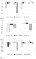
- Table 1 shows the optical properties of the film as initially obtained and after degradation for 150 hours subjecting the samples to a high temperature test (90°C/dry) (i.e. ambient humidity, approximately 2% relative humidity), a high temperature/high humidity test (60°C/90%rH) and a high flux test (blue LED light, 460nm blue emission, 280mW/cm2, 50°C, LEDcube100, Hoenle, Germany).
- the light intensity was measured with a UV meter equipped with a VIS area sensor (Hoenle, Germany).
- the resulting optical properties of the film were measured with a spectrofluorimeter equipped with an integrating sphere (Quantaurus Absolute PL quantum yield measuring system C1134711, Hamamatsu).
- Examples 5-6 Synthesis of luminescent components according to the invention (fully covered PI pieces in P2, c.f fig.4; Ex. 5 for comparison, ex. 6 according to the invention.)
- Ink formation The ink was prepared as described in examples 1-4.
- the first film was prepared like the first film of example 1.
- a second film (P1/P2-glass) was prepared by preparing a film as described for the first film above. Then this film was delaminated from the two glass slides and cut in small pieces approximately 0.5mm x 0.5mm x 0.1mm in size. These P1 pieces were then mix into a matrix of (0.7 g FA-DCPA, Hitachi Chemical, Japan / 0.3 g FA-320M, Hitachi Chemical, Japan) containing 1wt% photoinitiator Diphenyl(2,4,6-trimethylbenzoyl) phosphine oxide with a weight ratio of 1:3 (P1 pieces/matrix) and subsequently coated and cured as described above. The second film was coated such that the matrix fully covered the P1 pieces.
- Table 2 shows the optical properties of the film as initially obtained and after degradation for 150 hours subjecting the samples to a high temperature test (90°C/dry) (i.e. ambient humidity, approximately 2% relative humidity), a high temperature/high humidity test (60°C/90%rH) and a high flux test (blue LED light, 460nm blue emission, 350mW/cm2, 50°C, LEDcube100, Hoenle, Germany).
- the light intensity was measured with a UV meter equipped with a VIS area sensor (Hoenle, Germany).
- the resulting optical properties of the film were measured with a spectrofluorimeter equipped with an integrating sphere (Quantaurus Absolute PL quantum yield measuring system C1134711, Hamamatsu).
- Examples 7-10 Synthesis of luminescent components according to the invention (partially covered P1 in P2, c.f. fig. 2A, 2B, 2C ). Ex. 7, 8 and 9 for comparison, ex. 10 according to the invention.
- Ink formation The ink was prepared as described in examples 1-4.
- This barrier film exhibited a WVTR of 0.022 g/(m2*day) (Mocon test) based on the manufacturer's inspection report.
- Curing was done in a UV belt (BE20/120W/II, Beltron, Germany) equipped with two mercury lamp and quartz filter. Curing conditions were 31% lamp intensity for both lamps and 4.1 m/min line speed, resulting in a UV energy of about 850 mJ/cm2 measured with a UV integrator type D (Beltron, Germany).
- a second film (P2-barrier) was prepared as above with 0.3 g green ink and UV curable monomer/crosslinker mixture (2.1 g FA-DCPA, Hitachi Chemical, Japan / 0.9 g FA-320M, Hitachi Chemical, Japan) containing 1wt% photoinitiator Diphenyl(2,4,6-trimethylbenzoyl) phosphine oxide.
- Coating thickness was 100 ⁇ m and the curing conditions were 75% lamp intensity for both lamps and 5 m/min line speed, resulting in a UV energy of about 1700 mJ/cm2.
- a third film was prepared by first coating a 30 ⁇ m overcoat on two separate barrier films (TBF1004, i-components, Korea) with an UV curable monomer/crosslinker mixture (2.1 g FA-513AS, Hitachi Chemical, Japan / 0.9 g Miramer M240, Miwon, Korea) containing 1wt% photoinitiator Diphenyl(2,4,6-trimethylbenzoyl) phosphine oxide (TCI Europe, Netherlands).
- the overcoat was covered with a cellulose acetate viewfoil and subsequently curing was done with the UV belt at 31% lamp intensity for both lamps and 8.2 m/min line speed, resulting in a UV energy of about 425 mJ/cm2.
- a fourth film was prepared by first coating a 30 ⁇ m overcoat on two barrier films (TBF1004, i-components, Korea) with an UV curable monomer/crosslinker mixture (2.1 g FA-DCPA, Hitachi Chemical, Japan / 0.9 g FA-320M, Hitachi Chemical, Japan) containing 1wt% photoinitiator Diphenyl(2,4,6-trimethylbenzoyl) phosphine oxide (TCI Europe, Netherlands).
- the overcoat was covered with a cellulose acetate viewfoil and subsequently curing was done with the UV belt at 31% lamp intensity for both lamps and 8.2 m/min line speed, resulting in a UV energy of about 425 mJ/cm2.
- Table 3 shows the optical properties of the film as initially obtained and after degradation for 500 hours subjecting the samples to a high temperature test (90°C/dry) (i.e. ambient humidity, approximately 2% relative humidity), a high temperature/high humidity test (60°C/95%rH) and a high flux test (blue LED light, 460nm blue emission, 280mW/cm2, 50°C, LEDcube100, Hoenle, Germany).
- the light intensity was measured with a UV meter equipped with a VIS area sensor (Hoenle, Germany).
- the performance of the films was obtained by placing the samples on a magenta backlight unit and measuring the optical properties with a spectroradiometer (CS-2000, Konica Mi-nolta).
- the glass transition temperature of the elements of the luminescent component as described in this invention was determined by DSC according to DIN EN ISO 11357-2:2014-07 with a starting temperature of -90°C and an end temperature of 250°C and a heating rate of 20 K/min in nitrogen atmosphere (20 ml/min).
- the purging gas was nitrogen (5.0) at 20 ml/min.
- the DSC system DSC 204 F1 Phoenix (Netzsch) was used.
- the T g was determined on the second heating cycle (the first heating from -90°C to 250°C showed overlaying effects besides the glass transition).
- a first sample (P1+LCs) was prepared similar to the above films from example 7 by mixing 0.3 g of the green ink from example 1-4 with an UV curable monomer/crosslinker mixture (2.1 g FA-513AS, Hitachi Chemical, Japan / 0.9 g Miramer M240, Miwon, Korea) containing 1wt% photoinitiator Diphenyl(2,4,6-trimethylbenzoyl) phosphine oxide (TCI Europe, Netherlands) in a speed mixer and the toluene was subsequently evaporated by vacuum ( ⁇ 0.01 mbar) at room temperature. The resulting mixture was coated with a thickness of 30-40 ⁇ m between two 100 ⁇ m cellulose acetate viewfoils.
- an UV curable monomer/crosslinker mixture 2.1 g FA-513AS, Hitachi Chemical, Japan / 0.9 g Miramer M240, Miwon, Korea
- Diphenyl(2,4,6-trimethylbenzoyl) phosphine oxide TCI Europe,
- Curing was done in a UV belt (BE20/120W/II, Beltron, Germany) equipped with two mercury lamp and quartz filter. Curing conditions were 31% lamp intensity for both lamps and 1.0 m/min line speed, resulting in a UV energy of about 3400 mJ/cm2 measured with a UV integrator type D (Beltron, Germany).
- a second sample (P2) was prepared similar to the above films from example 10 by mixing an UV curable monomer/crosslinker mixture (2.1 g FA-DCPA, Hitachi Chemical, Japan / 0.9 g FA-320M, Hitachi Chemical, Japan) containing 1wt% photoinitiator Diphenyl(2,4,6-trimethylbenzoyl) phosphine oxide (TCI Europe, Netherlands) in a speed mixer. The resulting mixture was coated with a thickness of 30-40 ⁇ m between two 100 ⁇ m cellulose acetate viewfoils. Curing was done in a UV belt (BE20/120W/II, Beltron, Germany) equipped with two mercury lamp and quartz filter.
- UV curable monomer/crosslinker mixture 2.1 g FA-DCPA, Hitachi Chemical, Japan / 0.9 g FA-320M, Hitachi Chemical, Japan
- TCI Europe, Netherlands 1wt% photoinitiator Diphenyl(2,4,6-trimethylbenzoyl) phosphine oxide
- Example 7 shows inferior performance after degradation in (90/dry) and (60°C/90%rH) and example 8 performs significantly worse after degradation in (high flux), while example 9 shows a pronounced degradation in (90°C/dry) rendering these film systems unsuitable for application in TVs or the like.
Landscapes
- Chemical & Material Sciences (AREA)
- Organic Chemistry (AREA)
- Physics & Mathematics (AREA)
- Engineering & Computer Science (AREA)
- Materials Engineering (AREA)
- Inorganic Chemistry (AREA)
- Optics & Photonics (AREA)
- Nonlinear Science (AREA)
- Crystallography & Structural Chemistry (AREA)
- General Physics & Mathematics (AREA)
- Mathematical Physics (AREA)
- Wood Science & Technology (AREA)
- Life Sciences & Earth Sciences (AREA)
- General Engineering & Computer Science (AREA)
- Spectroscopy & Molecular Physics (AREA)
- Nanotechnology (AREA)
- Electromagnetism (AREA)
- Electroluminescent Light Sources (AREA)
- Luminescent Compositions (AREA)
- Optical Filters (AREA)
- Led Device Packages (AREA)
- Planar Illumination Modules (AREA)
- Addition Polymer Or Copolymer, Post-Treatments, Or Chemical Modifications (AREA)
Claims (16)
- Utilisation d'un polymère (P2) dans un composant luminescent (4), dans laquelle- ledit polymère (P2) est choisi dans le groupe des polymères réticulés avec Tg > 115°C et- ledit composant luminescent comprend des cristaux luminescents (11) de la structure cristalline de la perovskite noyés dans un polymère (P1) avec Tg < 95°C;chaque Tg étant mesurée selon la norme DIN EN ISO 11357-2:2014-07 pendant le deuxième cycle de chauffage et en appliquant une vitesse de chauffage de 20K/min, en commençant à -90°C jusqu'à 250°C.
- Un composant luminescent (4), comprenant un premier élément (1) et un second élément (2), dans lequel :- ledit premier élément (1) comprend une première composition polymère solide, ladite première composition polymère comprenant des premiers cristaux luminescents (11) noyés dans un premier polymère (P1),- lesdits premiers cristaux luminescents (11) étant de structure cristalline pérovskite et émettant une lumière d'une première longueur d'onde en réponse à une excitation par une lumière ayant une longueur d'onde plus courte que la première longueur d'onde,- ledit premier polymère (P1) étant choisi dans le groupe des polymères ayant une Tg < 95°C ;- ledit second élément (2) comprend une seconde composition polymère solide, ladite seconde composition polymère comprenant éventuellement des seconds cristaux luminescents (12) noyés dans un second polymère (P2),ledit second élément couvre au moins partiellement et scelle ainsi ledit premier élément ; et- lesdits seconds cristaux luminescents facultatifs (12) étant différents desdits premiers cristaux luminescents (11) et émettant une lumière d'une seconde longueur d'onde en réponse à une excitation par une lumière ayant une longueur d'onde plus courte que la seconde longueur d'onde,- ledit second polymère (P2) étant choisi dans le groupe des polymères réticulés ayant une Tg > 115°C ; et dans lequel
ladite Tg est mesurée comme défini dans la revendication 1. - Le composant luminescent selon la revendication 2, dans lequel P1 et / ou P2 sont conformes à un ou plusieurs des paramètres suivants :- P1 présente un rapport molaire de la somme de (oxygène + azote + soufre + phosphore + fluor + chlore + brome + iode) sur le carbone < 0,9, de préférence < 0,4, de préférence < 0,3, le plus préférablement < 0,25 ;- P2 a un rapport molaire de la somme de (oxygène + azote + soufre + phosphore + fluor + chlore + brome + iode) au carbone < 0,9, de préférence < 0,4, de préférence < 0,3, le plus préférablement < 0,20 ;- WVTR de P1 < 1 (g*mm)/(m2*jour), de préférence < 0,5 (g*mm)/(m2*jour), plus préférablement < 0,2 (g*mm)/(m2*jour) ;- WVTR de P2 < 1 (g*mm)/(m2*jour), de préférence < 0,5 (g*mm)/(m2*jour), plus préférablement < 0,2 (g*mm)/(m2*jour) ;- OTR de P1 > 1 (cm3*mm)/(m2*jour*atm), de préférence > 5 (cm3*mm)/(m2*jour*atm), de préférence > 25 (cm3*mm)/(m2*jour*atm), plus préférablement > 125 (cm3*mm)/(m2*jour*atm) ;- OTR de P2 < 50 (cm3*mm)/(m2*day*atm), de préférence < 10 (cm3*mm)/(m2*day*atm), de préférence < 5 (cm3*mm)/(m2*day*atm), plus préférablement < 1 (cm3*mm)/(m2*day*atm) ;- transmission de la lumière de P1 et P2 > 70 %, de préférence > 80 %, plus préférablement > 90 % à une épaisseur de 100 µm ;- dans lequel le premier polymère (P1) n'est pas dissoluble dans le second polymère (P2), et vice versa.
- Le composant luminescent selon la revendication 2 ou 3, dans lequel le premier polymère (P1) est choisi dans le groupe des polymères d'acrylate et dans lequel le second polymère (P2) est de préférence choisi dans le groupe des polymères d'acrylate.
- Le composant luminescent selon l'une des revendications 2 à 4, dans lequel le premier polymère (P1) comprend des unités répétitives de formules (III) et (V) et/ou le second polymère (P2) comprend des unités répétitives de formule (VI) et éventuellement de formule (III) :
 R9 représente H ou CH3,R10 représente un groupe alkyle en C1-25 cyclique, linéaire ou ramifié, ou un groupe aryle en C6-26, chacun étant éventuellement substitué par un ou plusieurs groupes alkyle en C1-20 cycliques, linéaires ou ramifiés, phényle ou phénoxy,n représente 0 ou 1, etX représente un espaceur du groupe des alcoxylates comprenant 1 à 8 atomes de carbone et 1 à 4 atomes d'oxygène ;
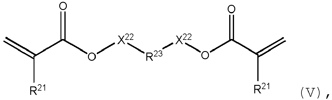 R21 représentent indépendamment les uns des autres H ou CH3 ;R23 représente un groupe alkyle en C1-25 cyclique, linéaire ou ramifié, ou un groupe aryle en C6-26, chacun étant éventuellement substitué par un ou plusieurs groupes alkyle en C1-20 cycliques, linéaires ou ramifiés, phényle ou phénoxy ;X22 représentent indépendamment l'un de l'autre un espaceur choisi dans le groupe des alcoxylates, les deux substituants X22 comprenant ensemble 8-40 atomes de carbone et 2-20 atomes d'oxygène ;
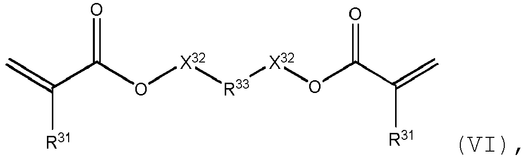 R31, indépendamment les uns des autres, représentent H ou CH3 ;R33 représente un groupe alkyle cyclique en C5-25, ou un groupe aryle en C6-26, chacun étant éventuellement substitué par un ou plusieurs groupes alkyle en C1-20 cycliques, linéaires ou ramifiés, phényle ou phénoxy ;X32 sont indépendants les uns des autres et sont soit absents, soit représentent un espaceur du groupe des alcoxylates, les deux substituants X32 comprenant ensemble 1 à 8 atomes de carbone et 1 à 8 atomes d'oxygène.
 - Le composant luminescent selon l'une des revendications 2 à 5, dans lequel les premiers cristaux luminescents (11) sont choisis parmi les composés de formule (I) :
[M1A1]aM2 bXc (I),
dans laquelle :A1 représente un ou plusieurs cations organiques,M1 représente un ou plusieurs métaux alcalins,M2 représente un ou plusieurs métaux autres que M1,X représente un ou plusieurs anions choisis dans le groupe constitué par les halogénures, les pseudohalogénures et les sulfures,a représente 1-4,b représente 1-2,c représente 3-9, etoù soit M1, soit A1, soit M1 et A1 étant présents ;
et / oudans lequel lesdits premiers cristaux luminescents (11) ont une taille comprise entre 3 et 100 nm. - Le composant luminescent selon l'une des revendications 2 à 6, dans lequel les seconds cristaux luminescents (12) sont choisis parmi un ou plusieurs des QD à cœur-coquille et des phosphores de taille micrométrique.
- Le composant luminescent selon l'une des revendications 2 à 7, comprenant en outre des troisièmes cristaux luminescents (13) choisis parmi un ou plusieurs des cristaux de pérovskite, des QD à cœur-coquille et des phosphores de taille micrométrique.
- Le composant luminescent selon l'une des revendications 2 à 8 sous la forme d'un film (4), en particulier un film de rétroéclairage QD ou un film de conversion vers le bas, ledit film comprenant la structure en couches suivante :- couche du premier élément (1)- couche du second élément (2) ; ou- couche du second élément (2) - couche du premier élément (1) - couche du second élément (2) ; ou- couche de protection (5) - couche du second élément (2) - couche du premier élément (1) - couche du second élément (2) - couche de protection (5).
- Le composant luminescent selon la revendication 9, dans lequel ladite couche de protection est choisie parmi- le verre ;- un polymère ayant des propriétés de barrière à l'humidité ;- un polymère ayant des propriétés de barrière à l'oxygène ;- un polymère revêtu d'une couche d'oxyde (de préférence du PET revêtu de SiOx ou AlOx.
- Le composant luminescent selon l'une des revendications 2 à 8, dans lequel- un ou plusieurs premiers éléments (1) sont disposés sur un substrat (3) et recouverts par une couche comprenant ledit second élément (2) ; ou- une couche comprenant ledit premier élément (1) est arrangée sur un substrat (3) et recouverte par une couche comprenant ledit second élément (2).
- Le composant luminescent selon l'une des revendications 2 - 8, dans lequel- une pluralité de premiers éléments (1) sont dispersés dans une matrice (5) et entièrement recouverts par le second élément (2).
- Un dispositif émetteur de lumière, comprenant- un composant luminescent selon l'une des revendications précédentes,- une source de lumière pour émettre de la lumière bleue,dans lequel la source de lumière est agencée pour exciter le composant luminescent.
- Le dispositif émetteur de lumière selon la revendication 13, choisi dans le groupe constitué par- les écrans, en particulier les écrans à cristaux liquides, les écrans OLED, les écrans QLED, les écrans micro LED ; et- les dispositifs d'éclairage, en particulier les LED, les OLED, les QLED.
- Utilisation d'un composant luminescent selon l'une des revendications précédentes 2 à 11, pour émettre de la lumière blanche en réponse à la radiation du composant luminescent (4) par de la lumière bleue, en particulier en tant que rétroéclairage dans un affichage à cristaux liquides.
- Procédé de fabrication d'un composant luminescent selon l'une des revendications 2 à 12, comprenant les étapes suivantes :* Méthode A *- fournir un substrat qui est éventuellement revêtu d'une ou plusieurs couches ;- appliquer sur ledit substrat une première composition polymère liquide comprenant des monomères ou oligomères du premier polymère P1, des premiers cristaux luminescents 11, optionnellement un solvant, optionnellement d'autres matériaux, optionnellement des troisièmes cristaux luminescents 13 ;- chauffer optionnellement ladite première composition de polymère liquide à une température élevée pour éliminer des solvants volatils.- durcir ladite première composition polymère liquide pour obtenir le premier élément ;- appliquer à la surface durcie ainsi obtenue dudit premier élément une seconde composition de polymère liquide comprenant des monomères ou oligomères du second polymère P2, optionnellement des seconds cristaux luminescents 12, optionnellement un solvant, optionnellement d'autres matériaux ;- chauffer optionnellement ladite seconde composition polymère liquide à une température élevée pour éliminer des solvants volatils.- durcir ladite composition liquide de second polymère pour obtenir le second élément, qui recouvre et scelle ainsi ledit premier élément ;- appliquer optionnellement d'autres étapes de revêtement ou de finition ; ou* Méthode B *- fournir un substrat qui est éventuellement revêtu d'une ou plusieurs couches ;- appliquer sur ledit substrat une seconde composition liquide de polymères telle que définie ci-dessus ;- chauffer optionnellement ladite deuxième composition polymère liquide à une température élevée pour éliminer des solvants volatils.- durcir ladite seconde composition polymère pour obtenir le deuxième élément ;- appliquer sur la surface durcie ainsi obtenue dudit second élément une première composition de polymère liquide telle que définie ci-dessus ;- chauffer optionnellement ladite première composition polymère liquide à une température élevée pour éliminer des solvants volatils.- durcir ladite première composition polymère liquide pour obtenir le premier élément, qui est recouvert et ainsi scellé par ledit second élément sur sa surface inférieure ;appliquer d'autres étapes de revêtement ou de finition ; ou* Méthode C *- fournir deux substrats, chacun revêtu d'une couche du second élément- laminer une couche de premiers éléments avec ces substrats revêtus ; ou* Méthode D *- fournir une première composition de polymère liquide comprenant des monomères ou oligomères du premier polymère P1, des premiers cristaux luminescents 11, optionnellement un solvant, optionnellement d'autres matériaux, optionnellement des troisièmes cristaux luminescents 13- l'une des opérations suivantesa) extraire multiples premiers éléments (1) de la première composition de polymère liquide par séchage par pulvérisation ou précipitation, oub) durcir la première composition de polymère liquide en une première composition de polymère solide, et écraser la première composition de polymère solide pour obtenir de multiples premiers éléments (1),- mélanger les premiers éléments (1) dans une seconde composition polymère liquide telle que définie ci-dessus, et- fournir un substrat qui est optionnellement revêtu d'une ou plusieurs couches ;- appliquer audit substrat ladite deuxième composition polymère liquide contenant les premiers éléments (1) ;- chauffer optionnellement ladite deuxième composition polymère liquide à une température élevée pour éliminer des solvants volatils.- durcir ladite deuxième composition polymère liquide pour obtenir le second élément, qui recouvre et scelle ainsi lesdits premiers éléments ;- appliquer optionnellement d'autres étapes de revêtement ou de finition.
Priority Applications (19)
| Application Number | Priority Date | Filing Date | Title |
|---|---|---|---|
| EP19180680.1A EP3753994B1 (fr) | 2019-06-17 | 2019-06-17 | Composant luminescent |
| EP21168668.8A EP3940038B1 (fr) | 2019-06-17 | 2019-06-17 | Composant luminescent |
| TW108139466A TWI754849B (zh) | 2019-06-17 | 2019-10-31 | 發光組件 |
| KR1020190155104A KR102185153B1 (ko) | 2019-06-17 | 2019-11-28 | 발광 구성요소 |
| CN201911239384.1A CN112103394B (zh) | 2019-06-17 | 2019-12-06 | 发光部件 |
| US16/894,144 US11008508B2 (en) | 2019-06-17 | 2020-06-05 | Luminescent component |
| CN202080044475.4A CN114040960B (zh) | 2019-06-17 | 2020-06-15 | 发光部件 |
| CN202211309272.0A CN115651635A (zh) | 2019-06-17 | 2020-06-15 | 发光部件 |
| JP2021574866A JP2022529079A (ja) | 2019-06-17 | 2020-06-15 | ルミネッセントコンポーネント |
| PCT/EP2020/066466 WO2020254236A1 (fr) | 2019-06-17 | 2020-06-15 | Composant luminescent |
| KR1020237011722A KR102717406B1 (ko) | 2019-06-17 | 2020-06-15 | 발광 구성요소 |
| US17/618,450 US11708528B2 (en) | 2019-06-17 | 2020-06-15 | Luminescent component |
| EP20732889.9A EP3959289B1 (fr) | 2019-06-17 | 2020-06-15 | Composant luminescent |
| KR1020217041272A KR102520198B1 (ko) | 2019-06-17 | 2020-06-15 | 발광 구성요소 |
| JP2020104606A JP7312146B2 (ja) | 2019-06-17 | 2020-06-17 | ルミネッセントコンポーネント |
| TW109120392A TWI838544B (zh) | 2019-06-17 | 2020-06-17 | 發光組件 |
| US17/230,212 US11958997B2 (en) | 2019-06-17 | 2021-04-14 | Luminescent component |
| JP2023019985A JP7699615B2 (ja) | 2019-06-17 | 2023-02-13 | ルミネッセントコンポーネント |
| US18/603,060 US12215262B2 (en) | 2019-06-17 | 2024-03-12 | Luminescent component |
Applications Claiming Priority (1)
| Application Number | Priority Date | Filing Date | Title |
|---|---|---|---|
| EP19180680.1A EP3753994B1 (fr) | 2019-06-17 | 2019-06-17 | Composant luminescent |
Related Child Applications (2)
| Application Number | Title | Priority Date | Filing Date |
|---|---|---|---|
| EP21168668.8A Division EP3940038B1 (fr) | 2019-06-17 | 2019-06-17 | Composant luminescent |
| EP21168668.8A Division-Into EP3940038B1 (fr) | 2019-06-17 | 2019-06-17 | Composant luminescent |
Publications (2)
| Publication Number | Publication Date |
|---|---|
| EP3753994A1 EP3753994A1 (fr) | 2020-12-23 |
| EP3753994B1 true EP3753994B1 (fr) | 2021-06-23 |
Family
ID=66951815
Family Applications (3)
| Application Number | Title | Priority Date | Filing Date |
|---|---|---|---|
| EP19180680.1A Active EP3753994B1 (fr) | 2019-06-17 | 2019-06-17 | Composant luminescent |
| EP21168668.8A Active EP3940038B1 (fr) | 2019-06-17 | 2019-06-17 | Composant luminescent |
| EP20732889.9A Active EP3959289B1 (fr) | 2019-06-17 | 2020-06-15 | Composant luminescent |
Family Applications After (2)
| Application Number | Title | Priority Date | Filing Date |
|---|---|---|---|
| EP21168668.8A Active EP3940038B1 (fr) | 2019-06-17 | 2019-06-17 | Composant luminescent |
| EP20732889.9A Active EP3959289B1 (fr) | 2019-06-17 | 2020-06-15 | Composant luminescent |
Country Status (7)
| Country | Link |
|---|---|
| US (4) | US11008508B2 (fr) |
| EP (3) | EP3753994B1 (fr) |
| JP (3) | JP2022529079A (fr) |
| KR (3) | KR102185153B1 (fr) |
| CN (3) | CN112103394B (fr) |
| TW (2) | TWI754849B (fr) |
| WO (1) | WO2020254236A1 (fr) |
Cited By (3)
| Publication number | Priority date | Publication date | Assignee | Title |
|---|---|---|---|---|
| US11506360B2 (en) * | 2018-10-22 | 2022-11-22 | Sharp Kabushiki Kaisha | Optical element and optical device |
| EP4180499A1 (fr) | 2022-10-27 | 2023-05-17 | Avantama AG | Film de conversion de couleur avec couche de séparation |
| US12396315B2 (en) | 2021-09-29 | 2025-08-19 | Korea Institute Of Science And Technology | Flexible transparent electrode structure having superior light transmittance, water permeation resistance and oxygen permeation resistance, method for preparing the same, and organic optoelectronic device using the same |
Families Citing this family (10)
| Publication number | Priority date | Publication date | Assignee | Title |
|---|---|---|---|---|
| EP3753994B1 (fr) | 2019-06-17 | 2021-06-23 | Avantama AG | Composant luminescent |
| TWI753624B (zh) * | 2020-10-26 | 2022-01-21 | 南亞塑膠工業股份有限公司 | 具有高可靠性的光學膜及其製作方法 |
| EP4101856A1 (fr) | 2021-06-09 | 2022-12-14 | Avantama AG | Composant luminescent modifié |
| US12545836B2 (en) | 2021-06-21 | 2026-02-10 | Nichia Corporation | Fluoride phosphor and method of producing the same, wavelength conversion member, and light emitting device |
| JP7335520B2 (ja) | 2021-06-21 | 2023-08-30 | 日亜化学工業株式会社 | 波長変換部材、発光装置及び画像表示装置 |
| CN113655658A (zh) * | 2021-07-27 | 2021-11-16 | 荣耀终端有限公司 | 一种背光源及其制作方法、显示装置、电子设备 |
| CN113956866B (zh) * | 2021-09-27 | 2023-08-22 | 华南理工大学 | 一种基于三羟甲基丙烷三丙烯酸酯掺杂的准二维钙钛矿薄膜及其制备方法与发光二极管 |
| JP2024141032A (ja) | 2023-03-28 | 2024-10-10 | キヤノン株式会社 | 光応答性組成物 |
| CN117358163A (zh) * | 2023-06-28 | 2024-01-09 | 深圳宇问测量技术有限公司 | 一种柔性一维纳米硫碘化锑复合材料的制备方法及其应用 |
| DE102024114516B3 (de) | 2024-05-23 | 2025-10-09 | Technische Universität Dresden, Körperschaft des öffentlichen Rechts | Phosphoreszierende Struktur, Verfahren zum Beschreiben einer phosphoreszierenden Struktur, Verfahren zum Löschen einer phosphoreszierenden Struktur und Verfahren zum Herstellen einer phosphoreszierenden Struktur |
Family Cites Families (33)
| Publication number | Priority date | Publication date | Assignee | Title |
|---|---|---|---|---|
| US20030222247A1 (en) * | 2002-01-28 | 2003-12-04 | Putman Everly Dean | Methods for manufacturing luminescent products having long afterglow |
| WO2007037393A1 (fr) * | 2005-09-29 | 2007-04-05 | The Furukawa Electric Co., Ltd. | Procédé de production de films multicouches, films multicouches et éléments optiques de films multicouches |
| KR100887869B1 (ko) * | 2006-08-03 | 2009-03-06 | 주식회사 엘지화학 | 내화학성이 향상된 다층 플라스틱 기판 및 그 제조 방법 |
| JP2008246862A (ja) * | 2007-03-30 | 2008-10-16 | Furukawa Electric Co Ltd:The | 樹脂積層フィルム及びその製造方法 |
| JP2009012187A (ja) * | 2007-06-29 | 2009-01-22 | Furukawa Electric Co Ltd:The | 積層フィルム及びその製造方法 |
| DE102008021666A1 (de) * | 2008-04-30 | 2009-11-05 | Ledon Lighting Jennersdorf Gmbh | Lichtemittierende Vorrichtung und Verfahren zur Herstellung einer lichtemittierenden Vorrichtung |
| GB0916700D0 (en) * | 2009-09-23 | 2009-11-04 | Nanoco Technologies Ltd | Semiconductor nanoparticle-based materials |
| JP2013509714A (ja) | 2009-10-30 | 2013-03-14 | ナノシス・インク. | ナノ結晶を含む発光ダイオード(led)デバイス |
| CN103597568B (zh) * | 2011-04-01 | 2016-08-17 | 纳晶科技股份有限公司 | 白光发光器件 |
| KR101336831B1 (ko) * | 2012-02-01 | 2013-12-04 | 주식회사 엘엠에스 | 양자점를 포함하는 조성물 및 이를 이용한 장치 |
| EP2913380B1 (fr) * | 2012-10-23 | 2017-04-12 | Mitsui Mining and Smelting Co., Ltd. | Luminophore, élément d'émission de lumière par del et dispositif de source lumineuse |
| AU2013365633B2 (en) * | 2012-12-20 | 2017-07-27 | Yissum Research Development Company Of The Hebrew University Of Jerusalem Ltd. | Perovskite schottky type solar cell |
| TWI606252B (zh) * | 2013-08-14 | 2017-11-21 | 納諾柯技術有限公司 | 使用多相樹脂的量子點薄膜及其製備方法 |
| EP3070109B1 (fr) * | 2015-03-16 | 2018-12-05 | Rohm and Haas Electronic Materials LLC | Composite de polymère multicouche pour encapsuler des points quantiques |
| CN104861958B (zh) | 2015-05-14 | 2017-02-15 | 北京理工大学 | 一种钙钛矿/聚合物复合发光材料及其制备方法 |
| JP6507309B2 (ja) * | 2015-08-19 | 2019-04-24 | スリーエム イノベイティブ プロパティズ カンパニー | 複合材物品及その製造方法 |
| JP6401680B2 (ja) * | 2015-08-28 | 2018-10-10 | 富士フイルム株式会社 | ガスバリアフィルムの製造方法およびガスバリアフィルムの転写方法 |
| JP6399982B2 (ja) * | 2015-08-28 | 2018-10-03 | 富士フイルム株式会社 | ガスバリアフィルムの製造方法 |
| EP3168278B2 (fr) * | 2015-10-28 | 2022-02-09 | Samsung Electronics Co., Ltd. | Points quantiques, leurs procédés de production et dispositifs électroniques les comprenant |
| EP3184602B1 (fr) * | 2015-12-23 | 2018-07-04 | Avantama AG | Composant luminescent |
| CN108603103B (zh) * | 2015-12-23 | 2021-09-03 | 凡泰姆股份公司 | 发光组件 |
| US10775671B2 (en) * | 2015-12-23 | 2020-09-15 | Avantama Ag | Display device |
| KR102653473B1 (ko) * | 2015-12-29 | 2024-04-01 | 삼성전자주식회사 | 양자점을 포함하는 전자 소자 |
| US10907092B2 (en) * | 2016-07-07 | 2021-02-02 | University Of Central Florida Research Foundation, Inc. | Methods of making highly stable perovskite-polymer composites and structures using same |
| KR20190031505A (ko) * | 2016-07-20 | 2019-03-26 | 쓰리엠 이노베이티브 프로퍼티즈 컴파니 | 양자점을 위한 안정화 스티렌계 중합체 |
| CN108026445B (zh) * | 2016-08-11 | 2022-06-21 | 凡泰姆股份公司 | 发光晶体和其制造 |
| EP3282000A1 (fr) * | 2016-08-11 | 2018-02-14 | Avantama AG | Composition polymère solide |
| WO2018051199A1 (fr) * | 2016-09-13 | 2018-03-22 | Efun Technology Co., Ltd. | Module électroluminescent à structure quantique |
| CN106750427B (zh) * | 2016-11-11 | 2020-08-11 | 致晶科技(北京)有限公司 | 一种钙钛矿量子点/聚合物复合荧光膜的制备方法 |
| EP3339394B1 (fr) * | 2016-12-22 | 2018-12-12 | Avantama AG | Matériaux composites luminescents |
| US10988686B2 (en) * | 2017-06-02 | 2021-04-27 | Nexdot | Luminescent particles comprising encapsulated nanoparticles and uses thereof |
| JP2020522749A (ja) * | 2017-06-02 | 2020-07-30 | ネクスドット | カプセル化されたナノ粒子を含むインク |
| EP3753994B1 (fr) | 2019-06-17 | 2021-06-23 | Avantama AG | Composant luminescent |
-
2019
- 2019-06-17 EP EP19180680.1A patent/EP3753994B1/fr active Active
- 2019-06-17 EP EP21168668.8A patent/EP3940038B1/fr active Active
- 2019-10-31 TW TW108139466A patent/TWI754849B/zh active
- 2019-11-28 KR KR1020190155104A patent/KR102185153B1/ko active Active
- 2019-12-06 CN CN201911239384.1A patent/CN112103394B/zh active Active
-
2020
- 2020-06-05 US US16/894,144 patent/US11008508B2/en active Active
- 2020-06-15 US US17/618,450 patent/US11708528B2/en active Active
- 2020-06-15 KR KR1020217041272A patent/KR102520198B1/ko active Active
- 2020-06-15 JP JP2021574866A patent/JP2022529079A/ja active Pending
- 2020-06-15 CN CN202080044475.4A patent/CN114040960B/zh active Active
- 2020-06-15 WO PCT/EP2020/066466 patent/WO2020254236A1/fr not_active Ceased
- 2020-06-15 EP EP20732889.9A patent/EP3959289B1/fr active Active
- 2020-06-15 CN CN202211309272.0A patent/CN115651635A/zh active Pending
- 2020-06-15 KR KR1020237011722A patent/KR102717406B1/ko active Active
- 2020-06-17 TW TW109120392A patent/TWI838544B/zh active
- 2020-06-17 JP JP2020104606A patent/JP7312146B2/ja active Active
-
2021
- 2021-04-14 US US17/230,212 patent/US11958997B2/en active Active
-
2023
- 2023-02-13 JP JP2023019985A patent/JP7699615B2/ja active Active
-
2024
- 2024-03-12 US US18/603,060 patent/US12215262B2/en active Active
Cited By (3)
| Publication number | Priority date | Publication date | Assignee | Title |
|---|---|---|---|---|
| US11506360B2 (en) * | 2018-10-22 | 2022-11-22 | Sharp Kabushiki Kaisha | Optical element and optical device |
| US12396315B2 (en) | 2021-09-29 | 2025-08-19 | Korea Institute Of Science And Technology | Flexible transparent electrode structure having superior light transmittance, water permeation resistance and oxygen permeation resistance, method for preparing the same, and organic optoelectronic device using the same |
| EP4180499A1 (fr) | 2022-10-27 | 2023-05-17 | Avantama AG | Film de conversion de couleur avec couche de séparation |
Also Published As
Similar Documents
| Publication | Publication Date | Title |
|---|---|---|
| EP3959289B1 (fr) | Composant luminescent | |
| KR102066378B1 (ko) | 고체 중합체 조성물 | |
| EP4101857B1 (fr) | Composant luminescent modifié |
Legal Events
| Date | Code | Title | Description |
|---|---|---|---|
| PUAI | Public reference made under article 153(3) epc to a published international application that has entered the european phase |
Free format text: ORIGINAL CODE: 0009012 |
|
| STAA | Information on the status of an ep patent application or granted ep patent |
Free format text: STATUS: THE APPLICATION HAS BEEN PUBLISHED |
|
| AK | Designated contracting states |
Kind code of ref document: A1 Designated state(s): AL AT BE BG CH CY CZ DE DK EE ES FI FR GB GR HR HU IE IS IT LI LT LU LV MC MK MT NL NO PL PT RO RS SE SI SK SM TR |
|
| AX | Request for extension of the european patent |
Extension state: BA ME |
|
| STAA | Information on the status of an ep patent application or granted ep patent |
Free format text: STATUS: REQUEST FOR EXAMINATION WAS MADE |
|
| GRAP | Despatch of communication of intention to grant a patent |
Free format text: ORIGINAL CODE: EPIDOSNIGR1 |
|
| STAA | Information on the status of an ep patent application or granted ep patent |
Free format text: STATUS: GRANT OF PATENT IS INTENDED |
|
| 17P | Request for examination filed |
Effective date: 20210308 |
|
| RBV | Designated contracting states (corrected) |
Designated state(s): AL AT BE BG CH CY CZ DE DK EE ES FI FR GB GR HR HU IE IS IT LI LT LU LV MC MK MT NL NO PL PT RO RS SE SI SK SM TR |
|
| INTG | Intention to grant announced |
Effective date: 20210413 |
|
| GRAS | Grant fee paid |
Free format text: ORIGINAL CODE: EPIDOSNIGR3 |
|
| GRAA | (expected) grant |
Free format text: ORIGINAL CODE: 0009210 |
|
| STAA | Information on the status of an ep patent application or granted ep patent |
Free format text: STATUS: THE PATENT HAS BEEN GRANTED |
|
| AK | Designated contracting states |
Kind code of ref document: B1 Designated state(s): AL AT BE BG CH CY CZ DE DK EE ES FI FR GB GR HR HU IE IS IT LI LT LU LV MC MK MT NL NO PL PT RO RS SE SI SK SM TR |
|
| REG | Reference to a national code |
Ref country code: GB Ref legal event code: FG4D |
|
| REG | Reference to a national code |
Ref country code: CH Ref legal event code: EP |
|
| REG | Reference to a national code |
Ref country code: DE Ref legal event code: R096 Ref document number: 602019005514 Country of ref document: DE Ref country code: AT Ref legal event code: REF Ref document number: 1404317 Country of ref document: AT Kind code of ref document: T Effective date: 20210715 |
|
| REG | Reference to a national code |
Ref country code: IE Ref legal event code: FG4D |
|
| REG | Reference to a national code |
Ref country code: LT Ref legal event code: MG9D |
|
| PG25 | Lapsed in a contracting state [announced via postgrant information from national office to epo] |
Ref country code: LT Free format text: LAPSE BECAUSE OF FAILURE TO SUBMIT A TRANSLATION OF THE DESCRIPTION OR TO PAY THE FEE WITHIN THE PRESCRIBED TIME-LIMIT Effective date: 20210623 Ref country code: HR Free format text: LAPSE BECAUSE OF FAILURE TO SUBMIT A TRANSLATION OF THE DESCRIPTION OR TO PAY THE FEE WITHIN THE PRESCRIBED TIME-LIMIT Effective date: 20210623 Ref country code: FI Free format text: LAPSE BECAUSE OF FAILURE TO SUBMIT A TRANSLATION OF THE DESCRIPTION OR TO PAY THE FEE WITHIN THE PRESCRIBED TIME-LIMIT Effective date: 20210623 Ref country code: BG Free format text: LAPSE BECAUSE OF FAILURE TO SUBMIT A TRANSLATION OF THE DESCRIPTION OR TO PAY THE FEE WITHIN THE PRESCRIBED TIME-LIMIT Effective date: 20210923 |
|
| REG | Reference to a national code |
Ref country code: AT Ref legal event code: MK05 Ref document number: 1404317 Country of ref document: AT Kind code of ref document: T Effective date: 20210623 |
|
| PG25 | Lapsed in a contracting state [announced via postgrant information from national office to epo] |
Ref country code: LV Free format text: LAPSE BECAUSE OF FAILURE TO SUBMIT A TRANSLATION OF THE DESCRIPTION OR TO PAY THE FEE WITHIN THE PRESCRIBED TIME-LIMIT Effective date: 20210623 Ref country code: NO Free format text: LAPSE BECAUSE OF FAILURE TO SUBMIT A TRANSLATION OF THE DESCRIPTION OR TO PAY THE FEE WITHIN THE PRESCRIBED TIME-LIMIT Effective date: 20210923 Ref country code: SE Free format text: LAPSE BECAUSE OF FAILURE TO SUBMIT A TRANSLATION OF THE DESCRIPTION OR TO PAY THE FEE WITHIN THE PRESCRIBED TIME-LIMIT Effective date: 20210623 Ref country code: RS Free format text: LAPSE BECAUSE OF FAILURE TO SUBMIT A TRANSLATION OF THE DESCRIPTION OR TO PAY THE FEE WITHIN THE PRESCRIBED TIME-LIMIT Effective date: 20210623 Ref country code: GR Free format text: LAPSE BECAUSE OF FAILURE TO SUBMIT A TRANSLATION OF THE DESCRIPTION OR TO PAY THE FEE WITHIN THE PRESCRIBED TIME-LIMIT Effective date: 20210924 |
|
| REG | Reference to a national code |
Ref country code: NL Ref legal event code: MP Effective date: 20210623 |
|
| PG25 | Lapsed in a contracting state [announced via postgrant information from national office to epo] |
Ref country code: NL Free format text: LAPSE BECAUSE OF FAILURE TO SUBMIT A TRANSLATION OF THE DESCRIPTION OR TO PAY THE FEE WITHIN THE PRESCRIBED TIME-LIMIT Effective date: 20210623 Ref country code: RO Free format text: LAPSE BECAUSE OF FAILURE TO SUBMIT A TRANSLATION OF THE DESCRIPTION OR TO PAY THE FEE WITHIN THE PRESCRIBED TIME-LIMIT Effective date: 20210623 Ref country code: PT Free format text: LAPSE BECAUSE OF FAILURE TO SUBMIT A TRANSLATION OF THE DESCRIPTION OR TO PAY THE FEE WITHIN THE PRESCRIBED TIME-LIMIT Effective date: 20211025 Ref country code: SM Free format text: LAPSE BECAUSE OF FAILURE TO SUBMIT A TRANSLATION OF THE DESCRIPTION OR TO PAY THE FEE WITHIN THE PRESCRIBED TIME-LIMIT Effective date: 20210623 Ref country code: CZ Free format text: LAPSE BECAUSE OF FAILURE TO SUBMIT A TRANSLATION OF THE DESCRIPTION OR TO PAY THE FEE WITHIN THE PRESCRIBED TIME-LIMIT Effective date: 20210623 Ref country code: AT Free format text: LAPSE BECAUSE OF FAILURE TO SUBMIT A TRANSLATION OF THE DESCRIPTION OR TO PAY THE FEE WITHIN THE PRESCRIBED TIME-LIMIT Effective date: 20210623 Ref country code: SK Free format text: LAPSE BECAUSE OF FAILURE TO SUBMIT A TRANSLATION OF THE DESCRIPTION OR TO PAY THE FEE WITHIN THE PRESCRIBED TIME-LIMIT Effective date: 20210623 Ref country code: EE Free format text: LAPSE BECAUSE OF FAILURE TO SUBMIT A TRANSLATION OF THE DESCRIPTION OR TO PAY THE FEE WITHIN THE PRESCRIBED TIME-LIMIT Effective date: 20210623 Ref country code: ES Free format text: LAPSE BECAUSE OF FAILURE TO SUBMIT A TRANSLATION OF THE DESCRIPTION OR TO PAY THE FEE WITHIN THE PRESCRIBED TIME-LIMIT Effective date: 20210623 |
|
| PG25 | Lapsed in a contracting state [announced via postgrant information from national office to epo] |
Ref country code: PL Free format text: LAPSE BECAUSE OF FAILURE TO SUBMIT A TRANSLATION OF THE DESCRIPTION OR TO PAY THE FEE WITHIN THE PRESCRIBED TIME-LIMIT Effective date: 20210623 |
|
| REG | Reference to a national code |
Ref country code: DE Ref legal event code: R097 Ref document number: 602019005514 Country of ref document: DE |
|
| PG25 | Lapsed in a contracting state [announced via postgrant information from national office to epo] |
Ref country code: DK Free format text: LAPSE BECAUSE OF FAILURE TO SUBMIT A TRANSLATION OF THE DESCRIPTION OR TO PAY THE FEE WITHIN THE PRESCRIBED TIME-LIMIT Effective date: 20210623 |
|
| PLBE | No opposition filed within time limit |
Free format text: ORIGINAL CODE: 0009261 |
|
| STAA | Information on the status of an ep patent application or granted ep patent |
Free format text: STATUS: NO OPPOSITION FILED WITHIN TIME LIMIT |
|
| 26N | No opposition filed |
Effective date: 20220324 |
|
| PG25 | Lapsed in a contracting state [announced via postgrant information from national office to epo] |
Ref country code: AL Free format text: LAPSE BECAUSE OF FAILURE TO SUBMIT A TRANSLATION OF THE DESCRIPTION OR TO PAY THE FEE WITHIN THE PRESCRIBED TIME-LIMIT Effective date: 20210623 |
|
| PG25 | Lapsed in a contracting state [announced via postgrant information from national office to epo] |
Ref country code: IT Free format text: LAPSE BECAUSE OF FAILURE TO SUBMIT A TRANSLATION OF THE DESCRIPTION OR TO PAY THE FEE WITHIN THE PRESCRIBED TIME-LIMIT Effective date: 20210623 |
|
| PG25 | Lapsed in a contracting state [announced via postgrant information from national office to epo] |
Ref country code: MC Free format text: LAPSE BECAUSE OF FAILURE TO SUBMIT A TRANSLATION OF THE DESCRIPTION OR TO PAY THE FEE WITHIN THE PRESCRIBED TIME-LIMIT Effective date: 20210623 |
|
| REG | Reference to a national code |
Ref country code: BE Ref legal event code: MM Effective date: 20220630 |
|
| PG25 | Lapsed in a contracting state [announced via postgrant information from national office to epo] |
Ref country code: LU Free format text: LAPSE BECAUSE OF NON-PAYMENT OF DUE FEES Effective date: 20220617 Ref country code: IE Free format text: LAPSE BECAUSE OF NON-PAYMENT OF DUE FEES Effective date: 20220617 |
|
| PG25 | Lapsed in a contracting state [announced via postgrant information from national office to epo] |
Ref country code: BE Free format text: LAPSE BECAUSE OF NON-PAYMENT OF DUE FEES Effective date: 20220630 |
|
| P01 | Opt-out of the competence of the unified patent court (upc) registered |
Effective date: 20230404 |
|
| PG25 | Lapsed in a contracting state [announced via postgrant information from national office to epo] |
Ref country code: MK Free format text: LAPSE BECAUSE OF FAILURE TO SUBMIT A TRANSLATION OF THE DESCRIPTION OR TO PAY THE FEE WITHIN THE PRESCRIBED TIME-LIMIT Effective date: 20210623 Ref country code: CY Free format text: LAPSE BECAUSE OF FAILURE TO SUBMIT A TRANSLATION OF THE DESCRIPTION OR TO PAY THE FEE WITHIN THE PRESCRIBED TIME-LIMIT Effective date: 20210623 |
|
| PG25 | Lapsed in a contracting state [announced via postgrant information from national office to epo] |
Ref country code: HU Free format text: LAPSE BECAUSE OF FAILURE TO SUBMIT A TRANSLATION OF THE DESCRIPTION OR TO PAY THE FEE WITHIN THE PRESCRIBED TIME-LIMIT; INVALID AB INITIO Effective date: 20190617 |
|
| PG25 | Lapsed in a contracting state [announced via postgrant information from national office to epo] |
Ref country code: TR Free format text: LAPSE BECAUSE OF FAILURE TO SUBMIT A TRANSLATION OF THE DESCRIPTION OR TO PAY THE FEE WITHIN THE PRESCRIBED TIME-LIMIT Effective date: 20210623 |
|
| PG25 | Lapsed in a contracting state [announced via postgrant information from national office to epo] |
Ref country code: MT Free format text: LAPSE BECAUSE OF FAILURE TO SUBMIT A TRANSLATION OF THE DESCRIPTION OR TO PAY THE FEE WITHIN THE PRESCRIBED TIME-LIMIT Effective date: 20210623 |
|
| PGFP | Annual fee paid to national office [announced via postgrant information from national office to epo] |
Ref country code: DE Payment date: 20250618 Year of fee payment: 7 |
|
| PGFP | Annual fee paid to national office [announced via postgrant information from national office to epo] |
Ref country code: GB Payment date: 20250618 Year of fee payment: 7 |
|
| PGFP | Annual fee paid to national office [announced via postgrant information from national office to epo] |
Ref country code: FR Payment date: 20250626 Year of fee payment: 7 |
|
| PGFP | Annual fee paid to national office [announced via postgrant information from national office to epo] |
Ref country code: CH Payment date: 20250701 Year of fee payment: 7 |