EP3754824B1 - Gaskinetischer transformator - Google Patents
Gaskinetischer transformator Download PDFInfo
- Publication number
- EP3754824B1 EP3754824B1 EP20153843.6A EP20153843A EP3754824B1 EP 3754824 B1 EP3754824 B1 EP 3754824B1 EP 20153843 A EP20153843 A EP 20153843A EP 3754824 B1 EP3754824 B1 EP 3754824B1
- Authority
- EP
- European Patent Office
- Prior art keywords
- plunger
- cylinder
- des
- yoke
- magnetisation
- Prior art date
- Legal status (The legal status is an assumption and is not a legal conclusion. Google has not performed a legal analysis and makes no representation as to the accuracy of the status listed.)
- Active
Links
Images


Classifications
-
- H—ELECTRICITY
- H02—GENERATION; CONVERSION OR DISTRIBUTION OF ELECTRIC POWER
- H02K—DYNAMO-ELECTRIC MACHINES
- H02K35/00—Generators with reciprocating, oscillating or vibrating coil system, magnet, armature or other part of the magnetic circuit
- H02K35/06—Generators with reciprocating, oscillating or vibrating coil system, magnet, armature or other part of the magnetic circuit with moving flux distributors, and both coil systems and magnets stationary
-
- F—MECHANICAL ENGINEERING; LIGHTING; HEATING; WEAPONS; BLASTING
- F01—MACHINES OR ENGINES IN GENERAL; ENGINE PLANTS IN GENERAL; STEAM ENGINES
- F01B—MACHINES OR ENGINES, IN GENERAL OR OF POSITIVE-DISPLACEMENT TYPE, e.g. STEAM ENGINES
- F01B11/00—Reciprocating-piston machines or engines without rotary main shaft, e.g. of free-piston type
-
- F—MECHANICAL ENGINEERING; LIGHTING; HEATING; WEAPONS; BLASTING
- F01—MACHINES OR ENGINES IN GENERAL; ENGINE PLANTS IN GENERAL; STEAM ENGINES
- F01B—MACHINES OR ENGINES, IN GENERAL OR OF POSITIVE-DISPLACEMENT TYPE, e.g. STEAM ENGINES
- F01B11/00—Reciprocating-piston machines or engines without rotary main shaft, e.g. of free-piston type
- F01B11/001—Reciprocating-piston machines or engines without rotary main shaft, e.g. of free-piston type in which the movement in the two directions is obtained by one double acting piston motor
-
- F—MECHANICAL ENGINEERING; LIGHTING; HEATING; WEAPONS; BLASTING
- F02—COMBUSTION ENGINES; HOT-GAS OR COMBUSTION-PRODUCT ENGINE PLANTS
- F02B—INTERNAL-COMBUSTION PISTON ENGINES; COMBUSTION ENGINES IN GENERAL
- F02B71/00—Free-piston engines; Engines without rotary main shaft
- F02B71/04—Adaptations of such engines for special use; Combinations of such engines with apparatus driven thereby
- F02B71/045—Adaptations of such engines for special use; Combinations of such engines with apparatus driven thereby with hydrostatic transmission
-
- H—ELECTRICITY
- H02—GENERATION; CONVERSION OR DISTRIBUTION OF ELECTRIC POWER
- H02K—DYNAMO-ELECTRIC MACHINES
- H02K35/00—Generators with reciprocating, oscillating or vibrating coil system, magnet, armature or other part of the magnetic circuit
-
- H—ELECTRICITY
- H02—GENERATION; CONVERSION OR DISTRIBUTION OF ELECTRIC POWER
- H02K—DYNAMO-ELECTRIC MACHINES
- H02K7/00—Arrangements for handling mechanical energy structurally associated with dynamo-electric machines, e.g. structural association with mechanical driving motors or auxiliary dynamo-electric machines
- H02K7/18—Structural association of electric generators with mechanical driving motors, e.g. with turbines
- H02K7/1807—Rotary generators
- H02K7/1815—Rotary generators structurally associated with reciprocating piston engines
-
- H—ELECTRICITY
- H02—GENERATION; CONVERSION OR DISTRIBUTION OF ELECTRIC POWER
- H02K—DYNAMO-ELECTRIC MACHINES
- H02K7/00—Arrangements for handling mechanical energy structurally associated with dynamo-electric machines, e.g. structural association with mechanical driving motors or auxiliary dynamo-electric machines
- H02K7/18—Structural association of electric generators with mechanical driving motors, e.g. with turbines
- H02K7/1869—Linear generators; sectional generators
- H02K7/1876—Linear generators; sectional generators with reciprocating, linearly oscillating or vibrating parts
Definitions
- the invention relates to power plants. It represents a linear generator that also functions as a motor.
- the invention converts the pressure energy of a gas medium into mechanical motion and electrical energy.
- the invention has a wide range of applications.
- the present invention makes it possible to supply gas supply networks and gas distribution points with energy. The gas pressure is reduced at these gas distribution points.
- the invention makes it possible to build simple energy storage systems to reduce peak loads.
- energy interruptions (voltage interruptions) can be avoided through the use of compressed air. Due to the simplicity and compactness of the device according to the invention, as well as the use of steam, compact devices can be developed for incidental energy production in heat supply networks for purposes of individual household economy.
- the application of the invention also makes it possible to utilize the exhaust heat from internal combustion engines.
- the mechanical and electrical parts are combined in one device. Rotating parts and transitions that require seals are excluded. This allows the housing to be hermetically sealed. This design of the housing prevents leaks and withstands high pressures. This makes it possible to use new steam-generating substances with higher boiling temperatures. Such substances include, for example, propylene glycol, glycerin and even sodium. As a result, the efficiency in the Carnot cycle can be significantly increased. In addition, due to the power generation plants of this cycle, plants with a higher degree of energy efficiency can be developed. In systems of this type, the external combustion of the fuel or the radiation source are used in heat generation.
- Linear generators are widespread in the field of technology. In such generators, vibration or other mechanical movements are used to generate electrical energy. As a rule, such devices have low performance.
- GB2332988A discloses a similar generator that uses linear oscillatory motion directly to generate electricity, the oscillatory motion being generated by an internal combustion engine.
- Devices are also known in which the linear generators are used as part of the internal combustion engine.
- Such devices are z. B. in the patents RU112537U1 and RU2453970 ( JP2008-027923 ) described.
- These devices are comparable to the invention since they include a part common to the engine and the generator.
- This superposition is very useful because it simplifies the construction of said devices.
- this superimposition of functions has not become a key factor that could serve the mass adoption of such devices.
- the main cause being widespread The reason why such devices stand in the way is probably due to the attempt to insert these devices into the cycle process of an internal combustion engine.
- the windings and parts of a magnet system are in direct contact with the combustion products. This makes implementation even more difficult.
- windings and permanent magnets must be repeatedly provided in the structure of the above device.
- an electrical linear generator which has a structure in which a cylinder wall, viewed from the inside outwards, has a coil, several permanent magnets arranged next to one another above it, and a magnetic body arranged above it as a stator.
- a magnetizable plunger actuator
- the magnetic body and, if applicable, the cylinder material itself, if it is made of magnetizable material must be permanently and completely remagnetized, which results in losses in energy generation .
- Another disadvantage is that the coil does not always have the full magnetic flux flowing through it, since the length of the plunger is significantly less than that of the coil, and the maximum possible energy is therefore not generated.
- an electrical linear generator which has a cylinder with a coil integrated into the cylinder wall, the material of the cylinder being unknown.
- the coil forms the stator and a plunger (actuator) made of permanent magnetic material is impelled by a fluid Cylinder reciprocated. If one assumes that the cylinder is made of non-magnetizable material, only comparatively little energy is generated due to the lack of a magnetic body in the stator. If, on the other hand, the cylinder is made of magnetizable material, the permanent magnetic reversal will result in high losses in energy production. Since the length of the coil is significantly greater than the length of the plunger, energy is only ever generated in that part of the coil that is just covered by the plunger.
- the CN 109113859A rejects one WO 2016/118062 A1 similar structure, the cylinder being made of a magnetizable material.
- the length of the plunger (actuator) essentially corresponds to the length of the coil, which results in a maximum magnetic flux, but in turn there are high losses in the energy generation in the cylinder, which acts as a magnetic body for the coil, due to its permanent magnetic reversal.
- the subject of the invention includes a device according to claim 1, which converts the energy of gaseous substances into electrical energy.
- the gaseous substances are under high pressure.
- the energy used in the invention is the energy of the gas or vapor under pressure. This broadens the scope of the invention. In addition, the requirements for the construction and the materials to be used are lower.
- Another important feature of the invention is that only one winding is required.
- the permanent magnets of a magnetic body are removed from the area of possibly high temperatures and are not affected by them. This makes it possible to use materials with lower Curie temperatures than in the prototypes.
- the plunger 7 moves inside the cylinder 8.
- the plunger is made of a material with a high magnetic permeability.
- the cylinder is designed with thin walls. It can be made of either a ferromagnetic or a paramagnetic material. With a small wall thickness, it does not play a major role. It is advisable that the material has a high electrical resistance. This is necessary in order to generate maximum resistance to the movement of the plunger. Such resistors are necessary for eddy currents in the circuits.
- the circuits are formed by the cylinder walls. The cylinder walls do not present any significant obstacles to a magnetic field. The cylinder walls thus separate the medium inside the cylinder from the outside medium.
- the cylinder is covered with covers 9 and 10 on both sides.
- the lids 9 and 10 have nozzles for supplying and removing a gaseous energy source.
- the plunger is located in the cylinder and forms cavities 11 and 12 within the cylinder, ie between the plunger itself and the cylinder heads.
- the cavities 11 and 12 have a changing volume. The changing volume depends on the position of the plunger.
- Damping springs 13 are used to store and return the kinetic energy of the plunger in the end points. The use of springs can be dispensed with if the supply of the energy source into the cavities is set up in a specific way.
- the kinetic energy of the plunger is absorbed and returned at the end points by the compression and expansion of the gaseous medium.
- the gas medium is in the cavities.
- a distributor of the compressed gaseous medium supplies this medium to the respective cavity 11 and 12 in alternation.
- the manifold is located externally with respect to the present device.
- the distributor can be of any of the types known in the art.
- the distributor can also repeat a version of the steam engine distributors from the 19th - 20th centuries.
- the distributor can be controlled via electrically controlled valves and a control pulse generator.
- the distributor can also be set up using channels in the plunger and openings at specific points in the cylinder. The openings control the flow of the energy carrier in exactly the same way as is done in two-stroke engines.
- the plunger shifts to the right. If at the same time the plunger was on the left before the start of movement, then it closed the magnetic flux flowing through the bars 3 and 5 of the magnet body and partially through the yoke 4. When the plunger shifts, it breaks this magnetic flux. The plunger moves to the right end position and closes the magnetic flux. This magnetic flux flows over the bars 3, 6 and partly over the yoke 4.
- the bars 5 and 6 are magnetized in opposite directions. Therefore, the polarity of the magnetic flux in the rod 3 changes with the movement (displacement) of the plunger.
- the plunger slides backwards from right to left.
- the plunger causes the change in the direction of flux through the rod 3 and thus through the coil with the winding 1.
- the magnetic fluxes in the elements 4, 5 and 6 of the magnetic body and in the plunger 7 do not change their directions. Because of this, they can be made of magnetically hard ferromagnetic materials. The core losses are relatively small.
- the rod 3 works in an alternating magnetic field.
- the rod 3 must be made of a magnetically soft ferromagnetic material with low core losses.
- the magnetization of the rod 5 has a downward vector.
- the magnetization of the bar 6 has an upward vector.
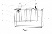
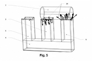
- the task of the modeling was to investigate the dependency between the magnitude and the direction of the magnetic flux in the central rod 3.
- the results of the calculation were presented in the calculation program in the form of vectors 14.
- the direction and size of the vectors correspond to the parameters of the magnetic flux in the vector position point.
- the voltage generated can be used to power loads both directly and using valve circuits (rectifier circuits) and conversion of electrical energy into specific forms. These forms correspond to those required by the consumer's requirements according to the parameters of frequency and rated voltage.
- the device Since the structure of the device is simple, the device can be implemented by most companies in the electrotechnical industry without high investments. The structure of the device and its simple operation make it possible to use well-established mathematical methods of designing electrical installations. The use of modern software further simplifies the use of these mathematical methods for practical purposes.
- the cylinder will be at a higher level than the coil (above the coil) together with the conductor and the magnetic body. This allows the heat generated when the current passes through the winding to flow in the direction of the cylinder. If steam is used, the cylinder will not heat the coil and magnet body.
- Ferromagnetic properties of the materials used to manufacture the magnet body in particular the Curie temperature, must be selected taking into account the temperature of the energy carrier.
- the functionality of the device was tested using a mathematical and a physical model.
Landscapes
- Engineering & Computer Science (AREA)
- Power Engineering (AREA)
- Mechanical Engineering (AREA)
- General Engineering & Computer Science (AREA)
- Chemical & Material Sciences (AREA)
- Combustion & Propulsion (AREA)
- Reciprocating, Oscillating Or Vibrating Motors (AREA)
Description
- Die Erfindung bezieht sich auf Kraftanlagen. Sie stellt einen Lineargenerator dar, der gleichzeitig als Motor funktioniert. Die Erfindung wandelt die Druckenergie eines Gasmediums in eine mechanische Bewegung und eine elektrische Energie um. Die Erfindung hat einen breiten Anwendungsbereich. Die vorliegende Erfindung ermöglicht es, Gasversorgungsnetze sowie Gasverteilungsstellen mit Energie zu versorgen. An diesen Gasverteilungsstellen wird der Gasdruck reduziert. Die Erfindung ermöglicht es, einfache Energiespeichersysteme zur Verminderung von Spitzenbelastungen zu bauen. Darüber hinaus lassen sich mit der Erfindung Energieunterbrechungen (Spannungsunterbrechungen) durch den Einsatz von Druckluft vermeiden. Aufgrund der Einfachheit und der Kompaktheit der Vorrichtung gemäß der Erfindung sowie dem Einsatz von Dampf können kompakte Vorrichtungen zur beiläufigen Energieerzeugung in Wärmeversorgungsnetzen für Zwecke der individuellen Hauswirtschaften entwickelt werden. Die Anwendung der Erfindung ermöglicht es auch, die Abgaswärme von Verbrennungsmotoren zu verwerten.
- In der Erfindung ist Folgendes umgesetzt: Die mechanischen und elektrischen Teile sind in einer Vorrichtung zusammengefasst. Rotierende Teile und Übergänge, für die Dichtungen erforderlich sind, sind ausgeschlossen. Dadurch kann das Gehäuse hermetisch dicht ausgeführt werden. Diese Ausführung des Gehäuses verhindert Lecks und hält hohen Drücken stand. Dies ermöglicht es, neue dampferzeugende Stoffe mit höheren Siedetemperaturen anzuwenden. Zu solchen Stoffen gehören zum Beispiel Propylenglycol, Glycerin und sogar Natrium. Dadurch kann der Wirkungsgrad im Carnot-Kreisprozess wesentlich erhöht werden. Darüber hinaus können aufgrund der Stromerzeugungsanlagen dieses Kreisprozesses Anlagen mit einem höheren Grad an Energieeffizienz entwickelt werden. In Anlagen dieser Art werden die äußere Verbrennung des Brennstoffs oder die Strahlungsquelle bei der Wärmebildung genutzt.
- Auf dem Gebiet der Technik sind Lineargeneratoren weit verbreitet. In solchen Generatoren wird die Vibration oder werden sonstige mechanische Bewegungen zur Erzeugung von elektrischer Energie verwendet. In der Regel weisen solche Vorrichtungen eine geringe Leistung auf.
-
GB2332988A RU112537U1 RU2453970 JP2008-027923 - In der
US 2014/265696 A1 ist ein elektrischer Generator beschrieben, der einen Aufbau mit einem innenliegenden Stator aus kreisförmig verteilten Magnetkörpern mit einer jeweils darauf angeordneten Spule und einem darum rotierenden Rotor mit verteilt darin angeordneten Permanentmagneten aufweist. - Aus der
EP 2 242 168 A1 geht ein elektrischer Lineargenerator hervor, der einen Aufbau aufweist, bei dem eine Zylinderwandung von innen nach außen betrachtet eine Spule, mehrere darüber nebeneinander angeordnete Permanentmagneten und einen darüber angeordneten Magnetkörper als Stator aufweist. Während der, durch eine Fluidbewegung verursachten, Hin- und Herbewegung eines magnetisierbaren Tauchkolbens (Aktors) im Zylinder muss der Magnetkörper und ggf. das Zylindermaterial selbst, falls dieses aus magnetisierbarem Material hergestellt ist, selbst permanent vollständig ummagnetisiert werden, wodurch Verluste bei der Energieerzeugung entstehen. Nachteilig ist außerdem, dass die Spule nicht ständig vollständig vom magnetischen Fluss durchflossen wird, da die Länge des Tauchkolbens wesentlich geringer ist als die der Spule, und deshalb nicht die maximal mögliche Energie erzeugt wird. - Aus der
WO 2016/118062 A1 ist ebenfalls ein elektrischer Lineargenerator bekannt, der einen Zylinder mit in die Zylinderwandung integrierter Spule aufweist, wobei das Material des Zylinders unbekannt ist. Die Spule bildet dabei den Stator und ein Tauchkolben (Aktor) aus permanentmagnetischem Material wird durch ein Fluid im Zylinder hin- und herbewegt. Wenn man unterstellt, dass der Zylinder aus nichtmagnetisierbarem Material besteht, dann wird durch das Fehlen eines Magnetkörpers im Stator nur vergleichsweise wenig Energie erzeugt. Sollte der Zylinder hingegen aus magnetisierbarem Material bestehen, so entstehen durch die permanente Ummagnetisierung hohe Verluste bei der Energieerzeugung. Da die Länge der Spule wesentlich größer als die Länge des Tauchkolbens ist, findet die Energieerzeugung außerdem immer nur in dem Teil der Spule statt, der gerade vom Tauchkolben überdeckt wird. - Die
CN 109113859 A weist einen zurWO 2016/118062 A1 ähnlichen Aufbau auf, wobei der Zylinder aus einem magnetisierbaren Material hergestellt ist. Die Länge des Tauchkolbens (Aktor) entspricht zwar im Wesentlichen der Länge der Spule, wodurch ein maximaler magnetischer Fluss gegeben ist, jedoch entstehen im Zylinder, der als Magnetkörper für die Spule wirkt, wiederum hohe Verluste bei der Energieerzeugung durch dessen permanente Ummagnetisierung. - Es ist unmöglich, einen optimalen Verlauf der Verbrennung und eine Kraftstoffunempfindlichkeit in Verbrennungsmotoren zu vereinigen. Aus diesem Grund kommt eine abweichende Art Energie in der vorliegenden Erfindung zum Einsatz. Offenbarung der Erfindung
- Zum Gegenstand der Erfindung gehört eine Vorrichtung nach Anspruch 1 , die die Energie gasförmiger Stoffe in elektrische Energie umwandelt. Die gasförmigen Stoffe stehen dabei unter hohem Druck.
- Die in der Erfindung zum Einsatz kommende Energie ist die Energie des unter Druck stehenden Gases oder Dampfes. Dies erweitert den Anwendungsbereich der Erfindung. Darüber hinaus sind dadurch die Anforderungen an die Konstruktion und die anzuwendenden Werkstoffe niedriger.
- Eine weitere wichtige Besonderheit der Erfindung besteht darin, dass nur eine Wicklung erforderlich ist. Die Permanentmagnete eines Magnetkörpers sind aus dem Bereich der eventuell hohen Temperaturen entfernt und befinden sich ausserhalb der Einwirkung von diesen. Dies ermöglicht es, Werkstoffe mit niedriegeren Curie-Temperaturen anzuwenden als bei den Prototypen.
- Die Erfindung wird nun anhand eines Ausführungsbeispiels näher erläutert. Es zeigen:
- Fig. 1
- eine Gesamtansicht der vorliegenden Vorrichtung;
- Fig. 2
- eine Schnittdarstellung des Zylinderteils der vorliegenden Vorrichtung; diese Schnittdarstellung zeigt die eingebauten Teile innerhalb des Zylinders; im Großen und Ganzen sieht die Vorrichtung wie eine Symbiose von Transformator und Dampfmaschine aus; darauf ist auch die Bezeichnung "Parotrans" ("Dampftrans") zurückzuführen.
- Es ist bekannt, dass es zur Erzeugung von elektrischer Energie in der Wicklung mit einem Leiter 1 notwendig ist, ein magnetisches Wechselfeld darin zu erzeugen. Dabei ist die Wicklung um eine Spule 2 gewickelt. Ist die Wicklung an einem Mittelstab 3 eines kammförmigen Magnetkörpers angeordnet, der aus einem Joch 4 und Seitenstäben 5 und 6 besteht, und werden dabei in den Seitenstäben 5 und 6 gegenläufig fließende magnetische Flüsse mit Hilfe von Einsätzen aus Permanentmagneten erzeugt, und wird eine konstante remanente Magnetisierung vorgegeben, so kann durch das Wechseln der Schlussgebung von magnetischen Flüssen der Seitenstäbe an dem Mittelstab eine wechselwirkende (schwingende) elektromotorische Kraft in der Wicklung erzeugt werden. Um solche periodischen Schlussgebungen eines magnetischen Flusses zu schaffen, wird ein Tauchkolben (Plunger) 7 eingesetzt. Der Tauchkolben 7 bewegt sich innerhalb des Zylinders 8. Der Tauchkolben wird aus einem Werkstoff mit einer hohen magnetischen Permeabilität ausgeführt. Der Zylinder wird dünnwandig ausgebildet. Er kann sowohl aus einem ferromagnetischen als auch einem paramagnetischen Werkstoff ausgeführt sein. Bei einer geringen Wandstärke spielt es keine große Rolle. Dabei ist es ratsam, dass der Werkstoff einen hohen elektrischen Widerstand aufweist. Dies ist erforderlich, um maximal hohe Widerstände bei der Bewegung des Tauchkolbens zu erzeugen. Solche Widerstände sind für Wirbelströme in den Stromkreisen nötig. Die Stromkreise werden durch die Zylinderwände gebildet. Die Zylinderwände stellen keine wesentlichen Hindernisse für ein Magnetfeld dar. So grenzen die Zylinderwände das Medium innerhalb des Zylinders vom Außenmedium ab. Dies ermöglicht es, die Aufgabe der Wärmeberechnung für die Wicklung und die Magnetkörperteile sowie die Aufgabe der Wärmeberechnung für die Bewegung des Tauchkolbens im Zylinder bei der Gestaltung der Vorrichtung und bei der Auswahl von deren Parametern getrennt zu betrachten. Der Zylinder ist von beiden Seiten mit Deckeln 9 und 10 zugedeckt. Die Deckel 9 und 10 haben Stutzen für die Zu- und Abführung eines gasförmigen Energieträgers. Der Tauchkolben befindet sich im Zylinder und bildet Hohlräume 11 und 12 innerhalb des Zylinders aus, d. h. zwischen dem Tauchkolben selbst und den Zylinderdeckeln. Die Hohlräume 11 und 12 weisen ein sich änderndes Volumen auf. Das sich ändernde Volumen hängt von der Position des Tauchkolbens ab. Dämpfungsfedern 13 dienen zur Speicherung und Rücklieferung der Bewegungsenergie des Tauchkolbens in den Endpunkten. Auf den Einsatz von Federn kann verzichtet werden, wenn die Zuführung des Energieträgers in die Hohlräume auf eine bestimmte Weise eingerichtet ist.
- In diesem Fall erfolgen die Aufnahme und die Rücklieferung der Bewegungsenergie des Tauchkolbens in den Endpunkten durch die Kompression und die Ausdehnung des Gasmediums. Das Gasmedium befindet sich in den Hohlräumen.
- Ein Verteiler des komprimierten gasförmigen Mediums führt dieses Medium abwechselnd dem jeweiligen Hohlraum 11 und 12 zu. Der Verteiler ist außerhalb in Bezug auf die vorliegende Vorrichtung angeordnet. Der Verteiler kann eine beliebige von den im Gebiet der Technik bekannten Ausführungen haben. Der Verteiler kann auch eine Ausführung der Verteiler der Dampfmaschinen aus dem 19. - 20. Jahrhundert wiederholen. Der Verteiler kann über elektrisch gesteuerte Ventile und einen Steuerimpulsgenerator gesteuert werden. Der Verteiler kann auch anhand von Kanälen im Tauchkolben und Durchbrechungen an bestimmten Stellen des Zylinders eingerichtet werden. Die Durchbrechungen steuern das Fließen des Energieträgers genauso, wie dies in Zweitaktmotoren realisiert ist.
- Wird ein gasförmiges Medium dem Hohlraum 11 unter einem hohen Druck zugeführt, verschiebt sich der Tauchkolben nach rechts. Wenn sich dabei der Tauchkolben vor dem Bewegungsbeginn links befand, dann schloss er den magnetischen Fluss, der über die Stäbe 3 und 5 des Magnetkörpers und teilweise über das Joch 4 floss. Wenn sich der Tauchkolben verschiebt, unterbricht er diesen magnetischen Fluss. Der Tauchkolben bewegt sich in die rechte Endposition und schließt den magnetischen Fluss. Dieser magnetische Fluss fließt über die Stäbe 3, 6 und teilweise über das Joch 4.
- Die Stäbe 5 und 6 sind ungleichsinnig magnetisiert. Deswegen ändert sich die Polarität des magnetischen Flusses im Stab 3 bei der Bewegung (Verlagerung) des Tauchkolbens. Wird ein Energieträger dem Hohlraum 12 zugeführt, verschiebt sich der Tauchkolben rückwärts von rechts nach links. Der Tauchkolben bewirkt wiederum die Änderung der Flussrichtung über den Stab 3 und somit über die Spule mit der Wicklung 1. Die magnetischen Flüsse in den Elementen 4, 5 und 6 des Magnetkörpers und im Tauchkolben 7 ändern ihre Richtungen nicht. Deswegen können sie aus magnetisch harten ferromagnetischen Materialien hergestellt werden. Die Ummagnetisierungsverluste sind dabei relativ gering.
- Der Stab 3 funktioniert in einem alternierenden Magnetfeld. Der Stab 3 muss aus einem magnetisch weichen ferromagnetischen Werkstoff mit geringen Ummagnetisierungsverlusten ausgebildet werden.
- In
Fig. 3 ,Fig. 4 undFig. 5 ist ein Teil der Ergebnisse einer mathematischen Modellierung eines magnetischen Flusses mit dem Tauchkolben in verschiedenen Positionen dargestellt. - Bei der Stellung der Aufgabe der Modellierung wurde vorgegeben, dass die Magnetisierung des Stabs 5 einen nach unten gerichteten Vektor hat. Die Magnetisierung des Stabs 6 hat einen nach oben gerichtetem Vektor.
- Die Aufgabe der Modellierung war es, die Abhängigkeit zwischen der Größe und der Richtung des magnetischen Flusses im Mittelstab 3 zu untersuchen. Die Ergebnisse der Berechnung wurden im Berechnungsprogramm in Form von Vektoren 14 dargestellt. Die Richtung und die Größe der Vektoren entsprechen den Parametern des magnetischen Flusses im Punkt der Vektorposition.
- In
Fig. 3 sind die Ergebnisse der Modellierung mit dem Tauchkolben in der linken Endposition gezeigt. Die ermittelten Ergebnisse zeigen, dass die Stäbe 5 und 3 die stärksten Flüsse haben. Der Fluss im Stab 3 ist dabei nach oben gerichtet. Der Fluss im Stab 6 ist schwach, da sein Magnetfeld nur über einen Luftspalt geschlossen werden kann. Dies lässt sich anhand der einzelnen kleinen unterschiedlich gerichteten Vektoren erkennen. Der Luftspalt hat dabei einen hohen magnetischen Widerstand. - In
Fig. 4 sind die Ergebnisse der Modellierung mit dem Tauchkolben in der Mittelposition dargestellt. Die Stäbe 5 und 6 haben heteropolare Magnetisierung gleicher Stärke und sind untereinander mit dem Joch von unten und dem Tauchkolben von oben geschlossen. Deswegen fließt der magnetische Fluss über den Tauchkolben, ohne in den Stab 3 zu gelangen. Hier lässt sich feststellen, dass im Stab 3 keine Magnetisierung vorliegt, wenn der Tauchkolben in der Mittelposition ist. Bewegt sich der Tauchkolben nach rechts, läuft der Vorgang ab, der inFig. 5 dargestellt ist. Die Stäbe 6 und 3 weisen die stärksten Flüsse auf. Der Fluss im Stab 3 ist dabei nach unten gerichtet. - Somit zeigt die Analyse der Vorgänge, die in
Fig. 3 ,Fig. 4 undFig. 5 dargestellt sind, Folgendes: Bei der Bewegung des Tauchkolbens aus einer Endposition in die andere ändert sich im Mittelstab die maximale Stärke des magnetischen Flusses einer Richtung auf die maximale Stärke der Gegenrichtung. Folglich wird in der Wicklung bei der Hin- und Rückbewegung des Tauchkolbens eine schwingende elektromotorische Kraft erzeugt. Die Wicklung ist am Mittelstab angeordnet. - Die erzeugte Spannung kann zur Speisung von Belastungen sowohl direkt als auch unter Einsatz von Ventilschaltungen (Gleichrichterschaltungen) und einer Umwandlung von elektrischer Energie in bestimmte Formen benutzt werden. Diese Formen entsprechen denjenigen, die gemäß den Anforderungen des Verbrauchers nach den Parametern der Frequenz und der Nennspannung erforderlich sind.
- Es zeigen:
- Fig. 1
- die Gesamtansicht der erfindungsgemäßen Vorrichtung. In der Figur sind dargestellt:
1 stromleitende Wicklung eines isolierten Leiters;
2 Spule für die Anordnung des Leiters und dessen Isolierung von einem Magnetkörper;
3 Mittelstab des Magnetkörpers;
4 Joch des Magnetkörpers;
5 Stab des Magnetkörpers; die Magnetisierung des Stabs 5 ist in der Richtung zum Joch hin vorgegeben;
6 Stab des Magnetkörpers; die Magnetisierung des Stabs 6 ist in der Richtung vom Joch her vorgegeben;
8 Zylinder;
9 linker Deckel des Zylinders mit einem Eintrittsstutzen;
10 rechter Deckel des Zylinders mit einem Eintrittsstutzen. - Fig. 2
- die Gesamtansicht der Vorrichtung mit dem Zylinder im Schnitt. Diese lässt die eingebauten Teile innerhalb des Zylinders erkennen. In der Figur sind dargestellt:
1 stromleitende Wicklung eines isolierten Leiters;
2 Spule für die Anordnung des Leiters und dessen Isolierung von einem Magnetkörper;
3 Mittelstab des Magnetkörpers;
4 Joch des Magnetkörpers;
5 Stab des Magnetkörpers; die Magnetisierung des Stabs 5 ist in der Richtung zum Joch hin vorgegeben;
6 Stab des Magnetkörpers; die Magnetisierung des Stabs 6 ist in der Richtung vom Joch her vorgegeben;
7 Tauchkolben;
8 Zylinder;
9 linker Deckel des Zylinders mit einem Eintrittsstutzen;
10 rechter Deckel des Zylinders mit einem Eintrittsstutzen;
11 Zylinderraum links von dem Tauchkolben;
12 Zylinderraum rechts von dem Tauchkolben;
13 Dämpfungsfedern. - Fig. 3
- einen Teil der Ergebnisse von Solid-Modelling des magnetischen Flusses in den Teilen des Magnetkörpers mit dem Tauchkolben in der linken Endposition. In der Figur sind dargestellt:
3 Mittelstab des Magnetkörpers;
4 Joch des Magnetkörpers;
5 Stab des Magnetkörpers; die Magnetisierung des Stabs 5 ist in der Richtung zum Joch hin vorgegeben;
6 Stab des Magnetkörpers; die Magnetisierung des Stabs 6 ist in der Richtung vom Joch her vorgegeben;
7 Tauchkolben;
14 Vektoren des magnetischen Flusses. - Fig. 4
- einen Teil der Ergebnisse von Solid-Modelling des magnetischen Flusses in den Teilen des Magnetkörpers mit dem Tauchkolben in der Mittelposition. In der Figur sind dargestellt:
3 Mittelstab des Magnetkörpers;
4 Joch des Magnetkörpers;
5 Stab des Magnetkörpers; die Magnetisierung des Stabs 5 ist in der Richtung zum Joch hin vorgegeben;
6 Stab des Magnetkörpers; die Magnetisierung des Stabs 6 ist in der Richtung vom Joch her vorgegeben;
7 Tauchkolben;
14 Vektoren des magnetischen Flusses. - Fig. 5
- einen Teil der Ergebnisse von Solid-Modelling des magnetischen Flusses in den Teilen des Magnetkörpers mit dem Tauchkolben in der rechten Endposition. In der Figur sind dargestellt:
3 Mittelstab des Magnetkörpers;
4 Joch des Magnetkörpers;
5 Stab des Magnetkörpers; die Magnetisierung des Stabs 5 ist in der Richtung zum Joch hin vorgegeben;
6 Stab des Magnetkörpers; die Magnetisierung des Stabs 6 ist in der Richtung vom Joch her vorgegeben;
7 Tauchkolben;
14 Vektoren des magnetischen Flusses. - Da der Aufbau der Vorrichtung einfach ist, lässt sich die Vorrichtung von den meisten Unternehmen der elektrotechnischen Industrie ohne hohe Investitionen umsetzen. Der Aufbau der Vorrichtung und eine einfache Funktionsweise ermöglichen es, gut bewährte mathematische Methoden der Auslegung der elektrischen Anlagen anzuwenden. Die Anwendung von moderner Software vereinfacht zusätzlich den Einsatz dieser mathematischen Methoden zu praktischen Zwecken.
- In den meisten Ausführungsformen der Vorrichtung wird sich der Zylinder auf einem höheren Niveau als die Spule (oberhalb der Spule) samt dem Leiter und dem Magnetkörper befinden. Dadurch kann die Wärme, die sich beim Stromdurchgang über die Wicklung bildet, in die Richtung zum Zylinder hin strömen. Falls Dampf eingesetzt wird, wird dabei der Zylinder die Spule und den Magnetkörper nicht erwärmen.
- Es sei erwähnt, dass in bestimmten Fällen es jedoch sinnvoll sein könnte, den Zylinder unterhalb der Spule und des Magnetkörpers anzuordnen.
- Ferromagnetische Eigenschaften der Werkstoffe für die Herstellung des Magnetkörpers, insbesondere die Curie-Temperatur, sind unter Berücksichtigung der Temperatur des Energieträgers zu wählen.
- Die Funktionsfähigkeit der Vorrichtung wurde anhand eines mathematischen und eines physikalischen Modells geprüft.
-
- 1.
RU 112537 U1 - 2.
RU 2453970 U1
Claims (5)
- Vorrichtung zur Erzeugung von Wechselstrom, umfassend einen kammförmigen Magnetkörper, der aus einem Joch und drei im Wesentlichen senkrecht dazu stehenden Stäben besteht, nämlich einem Mittelstab und zwei zum Mittelstab im Wesentlichen parallel stehenden Seitenstäben, eine Wicklung, die an dem Mittelstab angeordnet ist, einen Tauchkolben, der sich in einem Zylinder befindet und Hohlräume innerhalb des Zylinders ausbildet, wobei eine induzierte Spannung in der Wicklung durch die periodische Bewegung des Tauchkolbens entsteht, wobei der Tauchkolben (7) aus einem Werkstoff mit einer hohen magnetischen Permeabilität besteht, wobei der Tauchkolben (7) durch Dampf- oder Gasausdehnung in Bewegung gebracht ist, wobei der Dampf oder das Gas dabei unter Druck steht, und wobei der Dampf oder das Gas periodisch in den einen oder anderen Hohlraum des Zylinders (8) zugeführt ist, wobei der Tauchkolben in den Endpositionen jeweils einen der magnetischen Flüsse der Seitenstäbe über den Mittelstab schließt, und wobei die Seitenstäbe (5, 6) ungleichnamige permanente Magnetisierungen aufweisen.
- Vorrichtung nach Anspruch 1,
dadurch gekennzeichnet,
dass nur ein Teil des Tauchkolbens (7) aus einem Werkstoff mit einer hohen magnetischen Permeabilität ausgeführt ist. - Vorrichtung nach Anspruch 1,
dadurch gekennzeichnet,
dass der Tauchkolben (7) eine remanente Magnetisierung hat, die mit der Magnetisierung der Seitenstäbe (5, 6) übereinstimmt. - Vorrichtung nach Anspruch 1,
dadurch gekennzeichnet,
dass das Joch (4) des kammförmigen Magnetkörpers eine permanente Magnetisierung aufweist, die mit der Magnetisierung der Seitenstäbe (5, 6) übereinstimmt. - Vorrichtung nach Anspruch 1,
dadurch gekennzeichnet,
dass der Schnitt des Tauchkolbens (7) und des Zylinders (8) von einer runden Form abweicht.
Applications Claiming Priority (1)
| Application Number | Priority Date | Filing Date | Title |
|---|---|---|---|
| RU2019119365A RU2707266C1 (ru) | 2019-06-19 | 2019-06-19 | Газокинетический трансформатор "Паротранс" |
Publications (2)
| Publication Number | Publication Date |
|---|---|
| EP3754824A1 EP3754824A1 (de) | 2020-12-23 |
| EP3754824B1 true EP3754824B1 (de) | 2022-03-09 |
Family
ID=68653003
Family Applications (1)
| Application Number | Title | Priority Date | Filing Date |
|---|---|---|---|
| EP20153843.6A Active EP3754824B1 (de) | 2019-06-19 | 2020-01-27 | Gaskinetischer transformator |
Country Status (3)
| Country | Link |
|---|---|
| EP (1) | EP3754824B1 (de) |
| LT (1) | LT3754824T (de) |
| RU (1) | RU2707266C1 (de) |
Citations (1)
| Publication number | Priority date | Publication date | Assignee | Title |
|---|---|---|---|---|
| GB2332988A (en) * | 1997-12-31 | 1999-07-07 | Duncan Pinkerton | Opposed piston ic generator |
Family Cites Families (10)
| Publication number | Priority date | Publication date | Assignee | Title |
|---|---|---|---|---|
| SE521607C2 (sv) * | 2000-04-07 | 2003-11-18 | Abb Ab | En linjär elektrisk maskin |
| DE10242141A1 (de) * | 2002-09-03 | 2004-03-18 | Deutsches Zentrum für Luft- und Raumfahrt e.V. | Freikolben-Verbrennungsvorrichtung mit elektrischem Lineartrieb |
| JP4985262B2 (ja) | 2007-09-21 | 2012-07-25 | トヨタ自動車株式会社 | 燃料電池 |
| JP4415133B2 (ja) * | 2008-02-07 | 2010-02-17 | 隆逸 小林 | リニア発電装置 |
| US8729717B2 (en) * | 2010-11-04 | 2014-05-20 | GM Global Technology Operations LLC | Turbocompound free piston linear alternator |
| RU112537U1 (ru) * | 2011-06-10 | 2012-01-10 | Андрей Юрьевич Фокин | Электрический генератор переменного тока |
| US9461508B2 (en) * | 2012-05-30 | 2016-10-04 | Prototus, Ltd. | Electromagnetic generator transformer |
| SE541880C2 (sv) * | 2015-01-19 | 2020-01-02 | Noditech Ab | Anordning i en värmecykel för omvandling av värme till elektrisk energi |
| RU2586234C1 (ru) * | 2015-05-14 | 2016-06-10 | Федеральное государственное бюджетное образовательное учреждение высшего профессионального образования "Московский автомобильно-дорожный государственный технический университет (МАДИ)" | Источник автономного электропитания |
| CN109113859A (zh) * | 2018-07-17 | 2019-01-01 | 湖南宏达天恒汽车电子科技有限公司 | 一种直线往复式运动发电机、发电的方法和车辆 |
-
2019
- 2019-06-19 RU RU2019119365A patent/RU2707266C1/ru active
-
2020
- 2020-01-27 EP EP20153843.6A patent/EP3754824B1/de active Active
- 2020-01-27 LT LTEP20153843.6T patent/LT3754824T/lt unknown
Patent Citations (1)
| Publication number | Priority date | Publication date | Assignee | Title |
|---|---|---|---|---|
| GB2332988A (en) * | 1997-12-31 | 1999-07-07 | Duncan Pinkerton | Opposed piston ic generator |
Also Published As
| Publication number | Publication date |
|---|---|
| LT3754824T (lt) | 2022-06-27 |
| RU2707266C1 (ru) | 2019-11-26 |
| EP3754824A1 (de) | 2020-12-23 |
Similar Documents
| Publication | Publication Date | Title |
|---|---|---|
| DE60108115T2 (de) | Brennkraftmaschine mit freiem kolben und ventilen in den kolben | |
| AT514221B1 (de) | Druckluftspeicherkraftwerk mit Induktionspumpe | |
| DE69333487T2 (de) | Lineare elektrodynamische maschine und verfahren zu deren verwendung | |
| EP3400642B1 (de) | Druckluftspeicherkraftwerk | |
| DE10210735B4 (de) | Stirling-Maschine | |
| DE102012020486A1 (de) | Thermomagnetischer Generator | |
| EP1205019A1 (de) | Reluktanz-elektromaschine | |
| DE202014011204U1 (de) | Elektrische Maschine mit Nutverschluss | |
| EP2224580A2 (de) | Freikolbenvorrichtung mit elektrischem Lineartrieb | |
| DE1094889B (de) | Vorrichtung zur Umschliessung eines Plasmas von hoher Temperatur | |
| WO2022034105A1 (de) | Windkraftanlage mit zumindest einer dynamoelektrischen maschine | |
| EP1374261A1 (de) | Transformator mit forcierter flüssigkeitskühlung | |
| EP3754824B1 (de) | Gaskinetischer transformator | |
| EP0986696B1 (de) | Ventilanordnung für einen ventilgesteuerten verbrennungsmotor | |
| DE2828314A1 (de) | Ringfoermie lineare induktionspumpe mit einem extern gehalterten kanal | |
| DE2945973A1 (de) | Vorrichtung zur waermewandlung | |
| DE102020102713A1 (de) | Solenoid, das ein versetzbares ferromagnetisches Element innerhalb eines Luftspalts umfasst | |
| DE2237746A1 (de) | Einspritzventil fuer dieselbrennkraftmaschinen | |
| DE1283343B (de) | Magnetohydrodynamischer (MHD-) Energiewandler | |
| EP1869756B1 (de) | Linearaktor | |
| WO1997012207A9 (de) | Induktiver durchflussmesser | |
| DE202010011194U1 (de) | Magnetohydrodynamischer Wechselstromgenerator | |
| DE102016216655A1 (de) | Reluktanzmotor | |
| DE102005017482B4 (de) | Gaswechselventilaktor für einen ventilgesteuerten Verbrennungsmotor | |
| DE102006023654B3 (de) | Anordnung zur Erzeugung einer nichtlinearen Kraft- bzw. Drehmomentkennlinie |
Legal Events
| Date | Code | Title | Description |
|---|---|---|---|
| PUAI | Public reference made under article 153(3) epc to a published international application that has entered the european phase |
Free format text: ORIGINAL CODE: 0009012 |
|
| STAA | Information on the status of an ep patent application or granted ep patent |
Free format text: STATUS: EXAMINATION IS IN PROGRESS |
|
| 17P | Request for examination filed |
Effective date: 20200127 |
|
| AK | Designated contracting states |
Kind code of ref document: A1 Designated state(s): AL AT BE BG CH CY CZ DE DK EE ES FI FR GB GR HR HU IE IS IT LI LT LU LV MC MK MT NL NO PL PT RO RS SE SI SK SM TR |
|
| AX | Request for extension of the european patent |
Extension state: BA ME |
|
| RBV | Designated contracting states (corrected) |
Designated state(s): AL AT BE BG CH CY CZ DE DK EE ES FI FR GB GR HR HU IE IS IT LI LT LU LV MC MK MT NL NO PL PT RO RS SE SI SK SM TR |
|
| RIC1 | Information provided on ipc code assigned before grant |
Ipc: H02K 7/18 20060101ALI20211117BHEP Ipc: H02K 35/06 20060101ALI20211117BHEP Ipc: F02B 71/04 20060101AFI20211117BHEP |
|
| GRAP | Despatch of communication of intention to grant a patent |
Free format text: ORIGINAL CODE: EPIDOSNIGR1 |
|
| STAA | Information on the status of an ep patent application or granted ep patent |
Free format text: STATUS: GRANT OF PATENT IS INTENDED |
|
| RIC1 | Information provided on ipc code assigned before grant |
Ipc: F01B 11/00 20060101ALI20211210BHEP Ipc: H02K 7/18 20060101ALI20211210BHEP Ipc: H02K 35/06 20060101AFI20211210BHEP |
|
| GRAS | Grant fee paid |
Free format text: ORIGINAL CODE: EPIDOSNIGR3 |
|
| INTG | Intention to grant announced |
Effective date: 20220110 |
|
| GRAA | (expected) grant |
Free format text: ORIGINAL CODE: 0009210 |
|
| STAA | Information on the status of an ep patent application or granted ep patent |
Free format text: STATUS: THE PATENT HAS BEEN GRANTED |
|
| AK | Designated contracting states |
Kind code of ref document: B1 Designated state(s): AL AT BE BG CH CY CZ DE DK EE ES FI FR GB GR HR HU IE IS IT LI LT LU LV MC MK MT NL NO PL PT RO RS SE SI SK SM TR |
|
| REG | Reference to a national code |
Ref country code: CH Ref legal event code: EP Ref country code: AT Ref legal event code: REF Ref document number: 1474958 Country of ref document: AT Kind code of ref document: T Effective date: 20220315 |
|
| REG | Reference to a national code |
Ref country code: IE Ref legal event code: FG4D Free format text: LANGUAGE OF EP DOCUMENT: GERMAN |
|
| REG | Reference to a national code |
Ref country code: DE Ref legal event code: R096 Ref document number: 502020000753 Country of ref document: DE |
|
| REG | Reference to a national code |
Ref country code: NL Ref legal event code: MP Effective date: 20220309 |
|
| PG25 | Lapsed in a contracting state [announced via postgrant information from national office to epo] |
Ref country code: SE Free format text: LAPSE BECAUSE OF FAILURE TO SUBMIT A TRANSLATION OF THE DESCRIPTION OR TO PAY THE FEE WITHIN THE PRESCRIBED TIME-LIMIT Effective date: 20220309 Ref country code: RS Free format text: LAPSE BECAUSE OF FAILURE TO SUBMIT A TRANSLATION OF THE DESCRIPTION OR TO PAY THE FEE WITHIN THE PRESCRIBED TIME-LIMIT Effective date: 20220309 Ref country code: NO Free format text: LAPSE BECAUSE OF FAILURE TO SUBMIT A TRANSLATION OF THE DESCRIPTION OR TO PAY THE FEE WITHIN THE PRESCRIBED TIME-LIMIT Effective date: 20220609 Ref country code: HR Free format text: LAPSE BECAUSE OF FAILURE TO SUBMIT A TRANSLATION OF THE DESCRIPTION OR TO PAY THE FEE WITHIN THE PRESCRIBED TIME-LIMIT Effective date: 20220309 Ref country code: BG Free format text: LAPSE BECAUSE OF FAILURE TO SUBMIT A TRANSLATION OF THE DESCRIPTION OR TO PAY THE FEE WITHIN THE PRESCRIBED TIME-LIMIT Effective date: 20220609 |
|
| PG25 | Lapsed in a contracting state [announced via postgrant information from national office to epo] |
Ref country code: LV Free format text: LAPSE BECAUSE OF FAILURE TO SUBMIT A TRANSLATION OF THE DESCRIPTION OR TO PAY THE FEE WITHIN THE PRESCRIBED TIME-LIMIT Effective date: 20220309 Ref country code: GR Free format text: LAPSE BECAUSE OF FAILURE TO SUBMIT A TRANSLATION OF THE DESCRIPTION OR TO PAY THE FEE WITHIN THE PRESCRIBED TIME-LIMIT Effective date: 20220610 Ref country code: FI Free format text: LAPSE BECAUSE OF FAILURE TO SUBMIT A TRANSLATION OF THE DESCRIPTION OR TO PAY THE FEE WITHIN THE PRESCRIBED TIME-LIMIT Effective date: 20220309 |
|
| PG25 | Lapsed in a contracting state [announced via postgrant information from national office to epo] |
Ref country code: NL Free format text: LAPSE BECAUSE OF FAILURE TO SUBMIT A TRANSLATION OF THE DESCRIPTION OR TO PAY THE FEE WITHIN THE PRESCRIBED TIME-LIMIT Effective date: 20220309 |
|
| PG25 | Lapsed in a contracting state [announced via postgrant information from national office to epo] |
Ref country code: SM Free format text: LAPSE BECAUSE OF FAILURE TO SUBMIT A TRANSLATION OF THE DESCRIPTION OR TO PAY THE FEE WITHIN THE PRESCRIBED TIME-LIMIT Effective date: 20220309 Ref country code: SK Free format text: LAPSE BECAUSE OF FAILURE TO SUBMIT A TRANSLATION OF THE DESCRIPTION OR TO PAY THE FEE WITHIN THE PRESCRIBED TIME-LIMIT Effective date: 20220309 Ref country code: RO Free format text: LAPSE BECAUSE OF FAILURE TO SUBMIT A TRANSLATION OF THE DESCRIPTION OR TO PAY THE FEE WITHIN THE PRESCRIBED TIME-LIMIT Effective date: 20220309 Ref country code: PT Free format text: LAPSE BECAUSE OF FAILURE TO SUBMIT A TRANSLATION OF THE DESCRIPTION OR TO PAY THE FEE WITHIN THE PRESCRIBED TIME-LIMIT Effective date: 20220711 Ref country code: ES Free format text: LAPSE BECAUSE OF FAILURE TO SUBMIT A TRANSLATION OF THE DESCRIPTION OR TO PAY THE FEE WITHIN THE PRESCRIBED TIME-LIMIT Effective date: 20220309 Ref country code: EE Free format text: LAPSE BECAUSE OF FAILURE TO SUBMIT A TRANSLATION OF THE DESCRIPTION OR TO PAY THE FEE WITHIN THE PRESCRIBED TIME-LIMIT Effective date: 20220309 Ref country code: CZ Free format text: LAPSE BECAUSE OF FAILURE TO SUBMIT A TRANSLATION OF THE DESCRIPTION OR TO PAY THE FEE WITHIN THE PRESCRIBED TIME-LIMIT Effective date: 20220309 |
|
| PG25 | Lapsed in a contracting state [announced via postgrant information from national office to epo] |
Ref country code: PL Free format text: LAPSE BECAUSE OF FAILURE TO SUBMIT A TRANSLATION OF THE DESCRIPTION OR TO PAY THE FEE WITHIN THE PRESCRIBED TIME-LIMIT Effective date: 20220309 Ref country code: IS Free format text: LAPSE BECAUSE OF FAILURE TO SUBMIT A TRANSLATION OF THE DESCRIPTION OR TO PAY THE FEE WITHIN THE PRESCRIBED TIME-LIMIT Effective date: 20220709 Ref country code: AL Free format text: LAPSE BECAUSE OF FAILURE TO SUBMIT A TRANSLATION OF THE DESCRIPTION OR TO PAY THE FEE WITHIN THE PRESCRIBED TIME-LIMIT Effective date: 20220309 |
|
| REG | Reference to a national code |
Ref country code: DE Ref legal event code: R097 Ref document number: 502020000753 Country of ref document: DE |
|
| PLBE | No opposition filed within time limit |
Free format text: ORIGINAL CODE: 0009261 |
|
| STAA | Information on the status of an ep patent application or granted ep patent |
Free format text: STATUS: NO OPPOSITION FILED WITHIN TIME LIMIT |
|
| PG25 | Lapsed in a contracting state [announced via postgrant information from national office to epo] |
Ref country code: DK Free format text: LAPSE BECAUSE OF FAILURE TO SUBMIT A TRANSLATION OF THE DESCRIPTION OR TO PAY THE FEE WITHIN THE PRESCRIBED TIME-LIMIT Effective date: 20220309 |
|
| 26N | No opposition filed |
Effective date: 20221212 |
|
| PG25 | Lapsed in a contracting state [announced via postgrant information from national office to epo] |
Ref country code: SI Free format text: LAPSE BECAUSE OF FAILURE TO SUBMIT A TRANSLATION OF THE DESCRIPTION OR TO PAY THE FEE WITHIN THE PRESCRIBED TIME-LIMIT Effective date: 20220309 |
|
| PGFP | Annual fee paid to national office [announced via postgrant information from national office to epo] |
Ref country code: LT Payment date: 20230113 Year of fee payment: 4 Ref country code: FR Payment date: 20230124 Year of fee payment: 4 |
|
| PGFP | Annual fee paid to national office [announced via postgrant information from national office to epo] |
Ref country code: DE Payment date: 20230123 Year of fee payment: 4 |
|
| PG25 | Lapsed in a contracting state [announced via postgrant information from national office to epo] |
Ref country code: IT Free format text: LAPSE BECAUSE OF FAILURE TO SUBMIT A TRANSLATION OF THE DESCRIPTION OR TO PAY THE FEE WITHIN THE PRESCRIBED TIME-LIMIT Effective date: 20220309 |
|
| REG | Reference to a national code |
Ref country code: CH Ref legal event code: PL |
|
| PG25 | Lapsed in a contracting state [announced via postgrant information from national office to epo] |
Ref country code: LU Free format text: LAPSE BECAUSE OF NON-PAYMENT OF DUE FEES Effective date: 20230127 |
|
| REG | Reference to a national code |
Ref country code: BE Ref legal event code: MM Effective date: 20230131 |
|
| PG25 | Lapsed in a contracting state [announced via postgrant information from national office to epo] |
Ref country code: LI Free format text: LAPSE BECAUSE OF NON-PAYMENT OF DUE FEES Effective date: 20230131 Ref country code: CH Free format text: LAPSE BECAUSE OF NON-PAYMENT OF DUE FEES Effective date: 20230131 |
|
| PG25 | Lapsed in a contracting state [announced via postgrant information from national office to epo] |
Ref country code: BE Free format text: LAPSE BECAUSE OF NON-PAYMENT OF DUE FEES Effective date: 20230131 |
|
| PG25 | Lapsed in a contracting state [announced via postgrant information from national office to epo] |
Ref country code: IE Free format text: LAPSE BECAUSE OF NON-PAYMENT OF DUE FEES Effective date: 20230127 |
|
| PG25 | Lapsed in a contracting state [announced via postgrant information from national office to epo] |
Ref country code: MC Free format text: LAPSE BECAUSE OF FAILURE TO SUBMIT A TRANSLATION OF THE DESCRIPTION OR TO PAY THE FEE WITHIN THE PRESCRIBED TIME-LIMIT Effective date: 20220309 |
|
| PG25 | Lapsed in a contracting state [announced via postgrant information from national office to epo] |
Ref country code: MC Free format text: LAPSE BECAUSE OF FAILURE TO SUBMIT A TRANSLATION OF THE DESCRIPTION OR TO PAY THE FEE WITHIN THE PRESCRIBED TIME-LIMIT Effective date: 20220309 |
|
| REG | Reference to a national code |
Ref country code: DE Ref legal event code: R119 Ref document number: 502020000753 Country of ref document: DE |
|
| REG | Reference to a national code |
Ref country code: LT Ref legal event code: MM4D Effective date: 20240127 |
|
| GBPC | Gb: european patent ceased through non-payment of renewal fee |
Effective date: 20240127 |
|
| PG25 | Lapsed in a contracting state [announced via postgrant information from national office to epo] |
Ref country code: DE Free format text: LAPSE BECAUSE OF NON-PAYMENT OF DUE FEES Effective date: 20240801 Ref country code: LT Free format text: LAPSE BECAUSE OF NON-PAYMENT OF DUE FEES Effective date: 20240127 |
|
| PG25 | Lapsed in a contracting state [announced via postgrant information from national office to epo] |
Ref country code: GB Free format text: LAPSE BECAUSE OF NON-PAYMENT OF DUE FEES Effective date: 20240127 |
|
| PG25 | Lapsed in a contracting state [announced via postgrant information from national office to epo] |
Ref country code: FR Free format text: LAPSE BECAUSE OF NON-PAYMENT OF DUE FEES Effective date: 20240131 |
|
| PG25 | Lapsed in a contracting state [announced via postgrant information from national office to epo] |
Ref country code: LT Free format text: LAPSE BECAUSE OF NON-PAYMENT OF DUE FEES Effective date: 20240127 Ref country code: GB Free format text: LAPSE BECAUSE OF NON-PAYMENT OF DUE FEES Effective date: 20240127 Ref country code: FR Free format text: LAPSE BECAUSE OF NON-PAYMENT OF DUE FEES Effective date: 20240131 Ref country code: DE Free format text: LAPSE BECAUSE OF NON-PAYMENT OF DUE FEES Effective date: 20240801 |
|
| PGFP | Annual fee paid to national office [announced via postgrant information from national office to epo] |
Ref country code: AT Payment date: 20250417 Year of fee payment: 5 |
|
| PG25 | Lapsed in a contracting state [announced via postgrant information from national office to epo] |
Ref country code: CY Free format text: LAPSE BECAUSE OF FAILURE TO SUBMIT A TRANSLATION OF THE DESCRIPTION OR TO PAY THE FEE WITHIN THE PRESCRIBED TIME-LIMIT; INVALID AB INITIO Effective date: 20200127 |
|
| PG25 | Lapsed in a contracting state [announced via postgrant information from national office to epo] |
Ref country code: HU Free format text: LAPSE BECAUSE OF FAILURE TO SUBMIT A TRANSLATION OF THE DESCRIPTION OR TO PAY THE FEE WITHIN THE PRESCRIBED TIME-LIMIT; INVALID AB INITIO Effective date: 20200127 |
|
| PG25 | Lapsed in a contracting state [announced via postgrant information from national office to epo] |
Ref country code: TR Free format text: LAPSE BECAUSE OF FAILURE TO SUBMIT A TRANSLATION OF THE DESCRIPTION OR TO PAY THE FEE WITHIN THE PRESCRIBED TIME-LIMIT Effective date: 20220309 |
|
| REG | Reference to a national code |
Ref country code: AT Ref legal event code: MM01 Ref document number: 1474958 Country of ref document: AT Kind code of ref document: T Effective date: 20250127 |
|
| PG25 | Lapsed in a contracting state [announced via postgrant information from national office to epo] |
Ref country code: AT Free format text: LAPSE BECAUSE OF NON-PAYMENT OF DUE FEES Effective date: 20250127 |