EP3757352A2 - Aube et ensemble de noyau pour moteur de turbine à gaz et leur procédé de fabrication - Google Patents
Aube et ensemble de noyau pour moteur de turbine à gaz et leur procédé de fabrication Download PDFInfo
- Publication number
- EP3757352A2 EP3757352A2 EP20182444.8A EP20182444A EP3757352A2 EP 3757352 A2 EP3757352 A2 EP 3757352A2 EP 20182444 A EP20182444 A EP 20182444A EP 3757352 A2 EP3757352 A2 EP 3757352A2
- Authority
- EP
- European Patent Office
- Prior art keywords
- cavity
- airfoil
- core
- core structure
- purge
- Prior art date
- Legal status (The legal status is an assumption and is not a legal conclusion. Google has not performed a legal analysis and makes no representation as to the accuracy of the status listed.)
- Granted
Links
Images


Classifications
-
- F—MECHANICAL ENGINEERING; LIGHTING; HEATING; WEAPONS; BLASTING
- F01—MACHINES OR ENGINES IN GENERAL; ENGINE PLANTS IN GENERAL; STEAM ENGINES
- F01D—NON-POSITIVE DISPLACEMENT MACHINES OR ENGINES, e.g. STEAM TURBINES
- F01D5/00—Blades; Blade-carrying members; Heating, heat-insulating, cooling or antivibration means on the blades or the members
- F01D5/12—Blades
- F01D5/14—Form or construction
- F01D5/18—Hollow blades, i.e. blades with cooling or heating channels or cavities; Heating, heat-insulating or cooling means on blades
- F01D5/187—Convection cooling
-
- B—PERFORMING OPERATIONS; TRANSPORTING
- B22—CASTING; POWDER METALLURGY
- B22C—FOUNDRY MOULDING
- B22C9/00—Moulds or cores; Moulding processes
- B22C9/10—Cores; Manufacture or installation of cores
- B22C9/103—Multipart cores
-
- F—MECHANICAL ENGINEERING; LIGHTING; HEATING; WEAPONS; BLASTING
- F01—MACHINES OR ENGINES IN GENERAL; ENGINE PLANTS IN GENERAL; STEAM ENGINES
- F01D—NON-POSITIVE DISPLACEMENT MACHINES OR ENGINES, e.g. STEAM TURBINES
- F01D5/00—Blades; Blade-carrying members; Heating, heat-insulating, cooling or antivibration means on the blades or the members
- F01D5/12—Blades
- F01D5/14—Form or construction
- F01D5/20—Specially-shaped blade tips to seal space between tips and stator
-
- F—MECHANICAL ENGINEERING; LIGHTING; HEATING; WEAPONS; BLASTING
- F05—INDEXING SCHEMES RELATING TO ENGINES OR PUMPS IN VARIOUS SUBCLASSES OF CLASSES F01-F04
- F05D—INDEXING SCHEME FOR ASPECTS RELATING TO NON-POSITIVE-DISPLACEMENT MACHINES OR ENGINES, GAS-TURBINES OR JET-PROPULSION PLANTS
- F05D2230/00—Manufacture
- F05D2230/10—Manufacture by removing material
- F05D2230/12—Manufacture by removing material by spark erosion methods
-
- F—MECHANICAL ENGINEERING; LIGHTING; HEATING; WEAPONS; BLASTING
- F05—INDEXING SCHEMES RELATING TO ENGINES OR PUMPS IN VARIOUS SUBCLASSES OF CLASSES F01-F04
- F05D—INDEXING SCHEME FOR ASPECTS RELATING TO NON-POSITIVE-DISPLACEMENT MACHINES OR ENGINES, GAS-TURBINES OR JET-PROPULSION PLANTS
- F05D2230/00—Manufacture
- F05D2230/20—Manufacture essentially without removing material
- F05D2230/21—Manufacture essentially without removing material by casting
-
- F—MECHANICAL ENGINEERING; LIGHTING; HEATING; WEAPONS; BLASTING
- F05—INDEXING SCHEMES RELATING TO ENGINES OR PUMPS IN VARIOUS SUBCLASSES OF CLASSES F01-F04
- F05D—INDEXING SCHEME FOR ASPECTS RELATING TO NON-POSITIVE-DISPLACEMENT MACHINES OR ENGINES, GAS-TURBINES OR JET-PROPULSION PLANTS
- F05D2240/00—Components
- F05D2240/20—Rotors
- F05D2240/30—Characteristics of rotor blades, i.e. of any element transforming dynamic fluid energy to or from rotational energy and being attached to a rotor
- F05D2240/305—Characteristics of rotor blades, i.e. of any element transforming dynamic fluid energy to or from rotational energy and being attached to a rotor related to the pressure side of a rotor blade
-
- F—MECHANICAL ENGINEERING; LIGHTING; HEATING; WEAPONS; BLASTING
- F05—INDEXING SCHEMES RELATING TO ENGINES OR PUMPS IN VARIOUS SUBCLASSES OF CLASSES F01-F04
- F05D—INDEXING SCHEME FOR ASPECTS RELATING TO NON-POSITIVE-DISPLACEMENT MACHINES OR ENGINES, GAS-TURBINES OR JET-PROPULSION PLANTS
- F05D2240/00—Components
- F05D2240/20—Rotors
- F05D2240/30—Characteristics of rotor blades, i.e. of any element transforming dynamic fluid energy to or from rotational energy and being attached to a rotor
- F05D2240/306—Characteristics of rotor blades, i.e. of any element transforming dynamic fluid energy to or from rotational energy and being attached to a rotor related to the suction side of a rotor blade
-
- F—MECHANICAL ENGINEERING; LIGHTING; HEATING; WEAPONS; BLASTING
- F05—INDEXING SCHEMES RELATING TO ENGINES OR PUMPS IN VARIOUS SUBCLASSES OF CLASSES F01-F04
- F05D—INDEXING SCHEME FOR ASPECTS RELATING TO NON-POSITIVE-DISPLACEMENT MACHINES OR ENGINES, GAS-TURBINES OR JET-PROPULSION PLANTS
- F05D2240/00—Components
- F05D2240/20—Rotors
- F05D2240/30—Characteristics of rotor blades, i.e. of any element transforming dynamic fluid energy to or from rotational energy and being attached to a rotor
- F05D2240/307—Characteristics of rotor blades, i.e. of any element transforming dynamic fluid energy to or from rotational energy and being attached to a rotor related to the tip of a rotor blade
-
- F—MECHANICAL ENGINEERING; LIGHTING; HEATING; WEAPONS; BLASTING
- F05—INDEXING SCHEMES RELATING TO ENGINES OR PUMPS IN VARIOUS SUBCLASSES OF CLASSES F01-F04
- F05D—INDEXING SCHEME FOR ASPECTS RELATING TO NON-POSITIVE-DISPLACEMENT MACHINES OR ENGINES, GAS-TURBINES OR JET-PROPULSION PLANTS
- F05D2250/00—Geometry
- F05D2250/10—Two-dimensional
- F05D2250/18—Two-dimensional patterned
- F05D2250/185—Two-dimensional patterned serpentine-like
-
- F—MECHANICAL ENGINEERING; LIGHTING; HEATING; WEAPONS; BLASTING
- F05—INDEXING SCHEMES RELATING TO ENGINES OR PUMPS IN VARIOUS SUBCLASSES OF CLASSES F01-F04
- F05D—INDEXING SCHEME FOR ASPECTS RELATING TO NON-POSITIVE-DISPLACEMENT MACHINES OR ENGINES, GAS-TURBINES OR JET-PROPULSION PLANTS
- F05D2260/00—Function
- F05D2260/20—Heat transfer, e.g. cooling
-
- F—MECHANICAL ENGINEERING; LIGHTING; HEATING; WEAPONS; BLASTING
- F05—INDEXING SCHEMES RELATING TO ENGINES OR PUMPS IN VARIOUS SUBCLASSES OF CLASSES F01-F04
- F05D—INDEXING SCHEME FOR ASPECTS RELATING TO NON-POSITIVE-DISPLACEMENT MACHINES OR ENGINES, GAS-TURBINES OR JET-PROPULSION PLANTS
- F05D2260/00—Function
- F05D2260/60—Fluid transfer
- F05D2260/607—Preventing clogging or obstruction of flow paths by dirt, dust, or foreign particles
-
- Y—GENERAL TAGGING OF NEW TECHNOLOGICAL DEVELOPMENTS; GENERAL TAGGING OF CROSS-SECTIONAL TECHNOLOGIES SPANNING OVER SEVERAL SECTIONS OF THE IPC; TECHNICAL SUBJECTS COVERED BY FORMER USPC CROSS-REFERENCE ART COLLECTIONS [XRACs] AND DIGESTS
- Y02—TECHNOLOGIES OR APPLICATIONS FOR MITIGATION OR ADAPTATION AGAINST CLIMATE CHANGE
- Y02T—CLIMATE CHANGE MITIGATION TECHNOLOGIES RELATED TO TRANSPORTATION
- Y02T50/00—Aeronautics or air transport
- Y02T50/60—Efficient propulsion technologies, e.g. for aircraft
Definitions
- Illustrative embodiments pertain to the art of turbomachinery, and specifically to turbine rotor components.
- Gas turbine engines are rotary-type combustion turbine engines built around a power core made up of a compressor, combustor and turbine, arranged in flow series with an upstream inlet and downstream exhaust.
- the compressor compresses air from the inlet, which is mixed with fuel in the combustor and ignited to generate hot combustion gas.
- the turbine extracts energy from the expanding combustion gas, and drives the compressor via a common shaft. Energy is delivered in the form of rotational energy in the shaft, reactive thrust from the exhaust, or both.
- each spool is subdivided into a number of stages, which are formed of alternating rows of rotor blade and stator vane airfoils.
- the airfoils are shaped to turn, accelerate and compress the working fluid flow, or to generate lift for conversion to rotational energy in the turbine.
- Airfoils may incorporate various cooling cavities located adjacent external sidewalls and/or internal to the airfoil. Such cooling cavities are subject to both hot material walls (exterior or external) and cold material walls (interior or internal). Further, different cooling schemes may be necessary for blades and vanes due to operational parameters, environment, and/or conditions. Although such cavities are designed for cooling portions of airfoil bodies, improved cooling designs may be desirable.
- methods for forming airfoils for gas turbine engines include forming an airfoil body about a core assembly configured to define one or more internal cavities of the airfoil body, the core assembly comprising at least one core structure having a purge slot protrusion extending from a portion of the at least one core structure, removing the core assembly from the airfoil body to form one or more internal cavities, wherein at least one internal cavity has a cavity extension define by the purge slot protrusion, and forming a squealer pocket in a tip of the formed airfoil body, wherein a cavity purge slot is formed at the cavity extension to fluidly connect the respect internal cavity with the squealer pocket.
- the purge slot protrusion is a radially extending protrusion from a top of the at least one core structure, the radially extending protrusion is equal to or less than five times a width of the radially extending protrusion.
- further embodiments of the methods may include that at least one of the squealer pocket and the cavity purge slot are formed by an electrode discharge machining process.
- the core assembly comprises a plurality of core structures including a pressure side core structure and a suction side core structure, wherein the pressure side core structure defines a pressure side cavity in the formed airfoil body and the suction side core structure forms a suction side cavity in the formed airfoil, wherein the purge slot protrusion is on the suction side core.
- further embodiments of the methods may include that the core assembly further comprises a leading edge core structure and a trailing edge core structure.
- further embodiments of the methods may include forming at least one purge hole connecting the formed pressure side cavity by at least one of a purge hole rod and drilling.
- further embodiments of the methods may include that the core structure having the purge slot protrusion has a dimension in a direction from a pressure side to a suction side of the formed airfoil of about 0.075 inches (1.905 mm) or less.
- further embodiments of the methods may include that the width of the radially extending protrusion is equal to or greater than 0.014 inches (0.356 mm).
- width is a thickness of the radially extending protrusion in a direction between a pressure side and a suction side of the formed airfoil body.
- core assemblies for formation of airfoils for gas turbine engines include a core structure configured to define an internal cavity of an airfoil, the core structure extending from a base to a tip and a purge slot protrusion extending from a portion of the core structure proximate the tip, the purge slot protrusion configured to form a cavity extension in the formed airfoil.
- further embodiments of the core assemblies may include that the core structure having the purge slot protrusion has a dimension in a direction from a pressure side to a suction side of the formed airfoil of about 0.075 inches (1.905 mm) or less.
- further embodiments of the core assemblies may include that the core assembly comprises a plurality of core structures including a pressure side core structure and a suction side core structure, wherein the pressure side core structure defines a pressure side cavity in the formed airfoil body and the suction side core structure forms a suction side cavity in the formed airfoil, wherein the purge slot protrusion is on the suction side core.
- further embodiments of the core assemblies may include that the core assembly further comprises a leading edge core structure and a trailing edge core structure.
- further embodiments of the core assemblies may include that the pressure side core structure defines a serpentine structure configured to form a serpentine flow path within a formed airfoil.
- further embodiments of the core assemblies may include that the pressure side core structure includes one or more purge hole rods configured to form purge holes in a formed airfoil.
- airfoils for gas turbine engines include an airfoil body extending between a base and a tip, the airfoil body having an internal cooling cavity having a cavity extension located proximate the tip, a squealer pocket formed in the tip of the airfoil body, the squealer pocket having a pocket base that is recessed from the tip and extends toward the cavity extension, and a cavity purge slot forming an aperture to fluidly connect the internal cooling cavity to the squealer pocket through the recess.
- further embodiments of the airfoils may include that the internal cooling cavity has a dimension in a direction from a pressure side to a suction side of the airfoil body of about 0.075 inches (1.905 mm) or less.
- further embodiments of the airfoils may include that the airfoil body includes at least one additional internal cooling cavity, wherein at least one additional internal cooling cavity includes at least a pressure side cavity and the internal cooling cavity having the cavity extension is a suction side cavity.
- further embodiments of the airfoils may include that the at last one additional internal cavity further includes a leading edge cavity and a trailing edge cavity.
- further embodiments of the airfoils may include that the pressure side cavity defines a serpentine flow path within the airfoil body.
- further embodiments of the airfoils may include that the pressure side cavity includes one or more purge holes fluidly connecting the pressure side cavity to the squealer pocket.
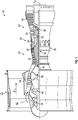
- FIG. 1 schematically illustrates a gas turbine engine 20.
- the gas turbine engine 20 is disclosed herein as a two-spool turbofan that generally incorporates a fan section 22, a compressor section 24, a combustor section 26 and a turbine section 28.
- the fan section 22 drives air along a bypass flow path B in a bypass duct, while the compressor section 24 drives air along a core flow path C for compression and communication into the combustor section 26 then expansion through the turbine section 28.
- FIG. 1 schematically illustrates a gas turbine engine 20.
- the gas turbine engine 20 is disclosed herein as a two-spool turbofan that generally incorporates a fan section 22, a compressor section 24, a combustor section 26 and a turbine section 28.
- the fan section 22 drives air along a bypass flow path B in a bypass duct
- the compressor section 24 drives air along a core flow path C for compression and communication into the combustor section 26 then expansion through the turbine section 28.
- the exemplary engine 20 generally includes a low speed spool 30 and a high speed spool 32 mounted for rotation about an engine central longitudinal axis A x relative to an engine static structure 36 via several bearing systems 38. It should be understood that various bearing systems 38 at various locations may alternatively or additionally be provided, and the location of bearing systems 38 may be varied as appropriate to the application.
- the low speed spool 30 generally includes an inner shaft 40 that interconnects a fan 42, a low pressure compressor 44 and a low pressure turbine 46.
- the inner shaft 40 can be connected to the fan 42 through a speed change mechanism, which in exemplary gas turbine engine 20 is illustrated as a geared architecture 48 to drive the fan 42 at a lower speed than the low speed spool 30.
- the high speed spool 32 includes an outer shaft 50 that interconnects a high pressure compressor 52 and high pressure turbine 54.
- a combustor 56 is arranged in exemplary gas turbine 20 between the high pressure compressor 52 and the high pressure turbine 54.
- An engine static structure 36 is arranged generally between the high pressure turbine 54 and the low pressure turbine 46.
- the engine static structure 36 further supports bearing systems 38 in the turbine section 28.
- the inner shaft 40 and the outer shaft 50 are concentric and rotate via bearing systems 38 about the engine central longitudinal axis A x which is collinear with their longitudinal axes.
- each of the positions of the fan section 22, compressor section 24, combustor section 26, turbine section 28, and fan drive gear system 48 may be varied.
- gear system 48 may be located aft of combustor section 26 or even aft of turbine section 28, and fan section 22 may be positioned forward or aft of the location of gear system 48.
- the engine 20 in one example is a high-bypass geared aircraft engine.
- the engine 20 bypass ratio is greater than about six (6), with an example embodiment being greater than about ten (10)
- the geared architecture 48 is an epicyclic gear train, such as a planetary gear system or other gear system, with a gear reduction ratio of greater than about 2.3 and the low pressure turbine 46 has a pressure ratio that is greater than about five.
- the engine 20 bypass ratio is greater than about ten (10:1)
- the fan diameter is significantly larger than that of the low pressure compressor 44
- the low pressure turbine 46 has a pressure ratio that is greater than about five (5:1).
- Low pressure turbine 46 pressure ratio is pressure measured prior to inlet of low pressure turbine 46 as related to the pressure at the outlet of the low pressure turbine 46 prior to an exhaust nozzle.
- the geared architecture 48 may be an epicyclic gear train, such as a planetary gear system or other gear system, with a gear reduction ratio of greater than about 2.3: 1. It should be understood, however, that the above parameters are only exemplary of one embodiment of a geared architecture engine and that the present disclosure is applicable to other gas turbine engines including direct drive turbofans.
- the fan section 22 of the engine 20 is designed for a particular flight conditiontypically cruise at about 0.8 Mach and about 35,000 feet (10,668 meters).
- "Low fan pressure ratio” is the pressure ratio across the fan blade alone, without a Fan Exit Guide Vane (“FEGV”) system.
- the low fan pressure ratio as disclosed herein according to one non-limiting embodiment is less than about 1.45.
- Low corrected fan tip speed is the actual fan tip speed in ft/sec divided by an industry standard temperature correction of [(Tram °R)/(514.7 °R)] 0.5 .
- the "Low corrected fan tip speed” as disclosed herein according to one non-limiting embodiment is less than about 1150 ft/second (350.5 m/sec).
- gas turbine engine 20 is depicted as a turbofan, it should be understood that the concepts described herein are not limited to use with the described configuration, as the teachings may be applied to other types of engines such as, but not limited to, turbojets, turboshafts, and turbofans wherein an intermediate spool includes an intermediate pressure compressor (“IPC") between a low pressure compressor (“LPC”) and a high pressure compressor (“HPC”), and an intermediate pressure turbine (“IPT”) between the high pressure turbine (“HPT”) and the low pressure turbine (“LPT”).
- IPC intermediate pressure compressor
- LPC low pressure compressor
- HPC high pressure compressor
- IPT intermediate pressure turbine
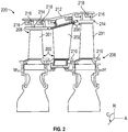
- FIG. 2 is a schematic view of a portion of a turbine section 200 that may employ various embodiments disclosed herein.
- the turbine section 200 includes a plurality of airfoils, including, for example, one or more blades 201 and vanes 202.
- the airfoils 201, 202 may be hollow bodies with internal cavities defining a number of channels or cavities, hereinafter airfoil cavities, formed therein and extending from an inner diameter 206 to an outer diameter 208, or vice-versa.
- the airfoil cavities may be separated by partitions or internal walls or structures within the airfoils 201, 202 that may extend either from the inner diameter 206 or the outer diameter 208 of the airfoil 201, 202, or as partial sections therebetween.
- the partitions may extend for a portion of the length of the airfoil 201, 202, but may stop or end prior to forming a complete wall within the airfoil 201, 202. Multiple of the airfoil cavities may be fluidly connected and form a fluid path within the respective airfoil 201, 202.
- the blades 201 and the vanes 202 are airfoils that extend from platforms 210 located proximal to the inner diameter thereof. Located below the platforms 210 may be airflow ports and/or bleed orifices that enable air to bleed from the internal cavities of the airfoils 201, 202.
- a root of the airfoil may connect to or be part of the platform 210. Such roots may enable connection to a turbine disc, as will be appreciated by those of skill in the art.
- the turbine 200 is housed within a case 212, which may have multiple parts (e.g., turbine case, diffuser case, etc.). In various locations, components, such as seals, may be positioned between the airfoils 201, 202 and the case 212.
- components such as seals, may be positioned between the airfoils 201, 202 and the case 212.
- blade outer air seals 214 (hereafter "BOAS") are located radially outward from the blades 201.
- the BOAS 214 can include BOAS supports that are configured to fixedly connect or attach the BOAS 214 to the case 212 (e.g., the BOAS supports can be located between the BOAS and the case). As shown in FIG.
- the case 212 includes a plurality of hooks 218 that engage with the hooks 216 to secure the BOAS 214 between the case 212 and a tip of the blade 201.
- other hooks are arranged to support the vane 202 within the case 212.
- a radial direction R is upward on the page (e.g., radial with respect to an engine axis, such as engine central longitudinal axis A x shown in FIG. 1 ) and an axial direction A is to the right on the page (e.g., along an engine axis).
- radial cooling flows will travel up or down on the page and axial flows will travel left-to-right (or vice versa).
- a circumferential direction C is a direction into and out of the page about the engine axis.
- Cooling of the airfoils 201, 202 may be achieved through internal cavities, as will be appreciated by those of skill in the art. Cooling air may be passed into and through the internal cavities, with the cooling air providing heat pick-up to remove heat from the hot material surfaces of the airfoil (e.g., external surfaces exposed to the hot gaspath).
- turbine engines ingest dirt, other particulates, debris, and other particles.
- Such particles may travel through the hot gaspath (i.e., through the compression and combustor systems) and may flow into the internal structures (i.e., cooling cavities) of the blades where the particles (along with the cooling air) is flung or pumped to the outer diameter or tips of the blades.
- the majority of these particles are extremely fine grain in size and can flow within the cooling air streams that are used to cool the internals of the blades.
- the particles may be too large to make abrupt turns inside the turbine blade internal passages, such as through serpentine cooling flows.
- a hole of sufficient size may be provided to fluidly connect the internal cavities with the external air (i.e., gas path) at the tip, and thus allow the relatively larger particles to exit the internal cavities.
- These holes are typically cast using alumina or quartz rods, drilled using electrodes or lasers, or are part of the trailing edge exit circuitry.
- the purge holes may be formed within a pocket or recess formed in the tip of the airfoil (e.g., tip pocket, a squealer pocket, squealer tip pocket, and/or tip shelf).
- the squealer pocket is configured to allow for air within the airfoil to exit into the gaspath without causing substantial inefficiencies in airflow. That is, air can exit internal cavities of the airfoil into the squealer pocket and align to flow while minimizing flow losses. Further, a portion of the air that exits the internal cavities may enter and remain within the tip pocket, at least for some amount of time, an provide cooling of the walls and base of the tip pocket, which can increase serviceable life of the tip of the airfoil.
- rods may connect a squealer pocket core to an internal cavity core in a core assembly to form the airfoil (although in some configurations the squealer pocket may be machined).
- the rods require that there be sufficient core material surrounding the rod to ensure that the rod can be held in place during the casting process.
- the core material is the material that defines the shape, volume, and dimensions of a cavity within a formed airfoil. That is, the core material is the negative of the cooling cavity, with the airfoil body material cast around the core. Because of this, a minimum thickness or dimension must be present in the core to support the rod.
- a minimum thickness of the core must be on the order of about 0.1 inches (about 2.54 mm) plus the diameter of the rod.
- Typical dirt purge holes may have a diameter of about .015-.035 inches (about .381-.889 mm).
- a circumferential thickness i.e., a direction from pressure side to suction side of a formed airfoil
- a minimum dimension of the cavity core may be dictated by the requirements of purging the cavity to prevent particle accumulation.
- An alternative method of forming such tip purge holes is to form holes into the tip using an electrode (e.g., electrode discharge machining).
- electrode e.g., electrode discharge machining
- Such methods require that the core be at least .060 inches (1.524 mm) thick.
- the core may still be a risk of scarfing the internal passages when forming the holes, thus impacting the internal cooling scheme and structural integrity of the formed airfoil.
- Embodiments of the present disclosure are directed to cores, core assemblies, and formed airfoils having cooling cavities with dimensions lower than the prior minimums.
- Embodiments of the present disclosure are directed to, in part, airfoil cavity core bodies that include an extension from a tip region to form a purge hole in the tip of a formed airfoil.
- the tip purge holes may be formed using an integral structure of the cavity core bodies (e.g., a core extension) that is subsequently machined (e.g., by electrical discharge machining ("EDM”)).
- EDM electrical discharge machining
- Such thin cores are formed with a radial protrusion that is the width of the desired purge hole, with such protrusion extending radially from an end of a core (e.g., core to form part of a serpentine cavity).
- the radial length (or height from the top of a core) of the core protrusion may be sized to take into account desired dimensions (e.g., axial length, circumferential width, etc.) of the purge hole and any core shift and profile tolerances in addition to any machined tip pocket tolerances.
- a tip-pocket electrode may be used to form a tip pocket and intersects with the integrally formed protrusion (defined by the core protrusion).
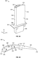
- FIGS. 3A-3B schematic illustrations of an airfoil 300 in accordance with an embodiment of the present disclosure is shown.
- the airfoil 300 includes an airfoil body 302 that extends in a radial direction from a platform 304.
- An attachment mechanism 306 extends from an opposing side of the platform 304 from the airfoil body 302 and is configured to enable engagement with a disk of a gas turbine engine.
- the airfoil 300 in this illustrative configuration, is a blade for use with a compressor or turbine section of a gas turbine engine.
- FIG. 3A is an isometric elevation view of the airfoil 300 and
- FIG. 3B is a top down illustration of the airfoil 300.
- the airfoil body 302 extends between a base 308 at the platform 304 and a tip 310, in a radial direction R. In an axial direction A, the airfoil body 302 extends between a leading edge 312 and a trailing edge 314. In a circumferential direction C, the airfoil body 302 extends between a pressure side 316 and a suction side 318.
- the directions described herein are relative to an engine axis (e.g., engine central longitudinal axis A x shown in FIG. 1 ).
- the airfoil body 302 may include one or more internal cooling cavities, as will be appreciated by those of skill in the art.
- the cooling cavities can include conventional cavities or hybrid or skin core cavities.
- Conventional cavities are cavities that are defined between external hot walls of the airfoil, such as from the pressure side 316 to the suction side 318 in the circumference direction C.
- a conventional cooling cavity provides cooling to two hot walls of the airfoil body.
- a hybrid or skin core cavity is one that is defined between an external hot wall of the airfoil body and an internal cold wall (a wall that is not exposed to hot external gases).
- the hybrid or skin core cavities have low height (i.e., circumferential direction C) to width (i.e., axial direction A) aspect ratios, with a flow direction being normal to the height and width (i.e., radial direction R). That is, the hybrid or skin core cavities has thin thicknesses in a direction from the pressure side 316 to the suction side 318 (i.e., less than full thickness of internal size of the airfoil body), whereas a conventional cavity would have a full thickness from the pressure side 316 to the suction side 318 (two hot walls).
- a squealer pocket 320 At the tip 310 of the airfoil 300 is a squealer pocket 320.
- the squealer pocket 320 can provide a volume for air exiting the internal cavities of the airfoil 300 to align and flow together before entering a hot gaspath, and thus reduce losses associated with such merging of flows.
- the squealer pocket 320 may include one or more apertures that fluidly connect the squealer pocket 320 to the internal cavities of the airfoil 300.
- FIG. 3B illustrates a top down view of the tip 310 and the squealer pocket 320.
- the squealer pocket 320 is defined by a pocket base 322 and walls of the airfoil body 302 (leading edge, pressure side, suction side).
- the pocket base 322 is recessed relative to the tip 310.
- the squealer pocket 320 includes two main body cavity purge holes 324.
- the main body cavity purge holes 324 may fluidly connect to one or more main body cavities within the airfoil body 302.
- the main body cavity purge holes 324 may be fluidly connected at two distinct locations along a serpentine cavity arranged along the pressure side 316 of the airfoil body 302.
- the pocket base 322 further includes a cavity purge slot 326 formed within the squealer pocket 320 and extending radially inward from the pocket base 322.
- the cavity purge slot 326 may form a fluid connection between an internal cavity of the airfoil body 302 and the squealer pocket 320.
- the main body cavity purge holes 324 may be formed by drilling or rods during a casting process.
- the main body cavity purge holes 324 may connected to conventional cavities or to skin core cavities.
- the core used to form the conventional cavities or skin core cavities must be of sufficient dimensions to accommodate the rods or drilling operation.
- the cavity purge slot 326 is formed to connect to a cavity having dimensions that do not permit the use of rods or drilling. That is, the cavity to which the cavity purge slot 326 connects may have a thickness in a direction between the pressure side 316 and the suction side 318 that does not allow for rods or drilling for forming purge holes.
- the cavity (and core used to form such cavity) may have a thickness in the direction between the pressure side 316 and the suction side 318 of 0.060 inches (1.524 mm) or less.
- an electrical discharge machining (“EDM”) process may be employed to remove material at the tip 310 and allow for connection with a core extension used to form the cavity purge slot 326.
- the EDM process may be used to cut into a formed airfoil body and thus form the squealer pocket 320 in the tip 310 of the airfoil 300.
- the removal of material during the EDM process employs an electrode having a desired geometry to form the squealer pocket 320.
- the internal cavities (and particularly the cavity to have the cavity purge slot 326) are formed with specific geometries and/or features to enable the airfoil 300 to be formed.
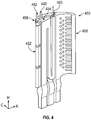
- FIG. 4 a schematic illustration of a core assembly 450 in accordance with an embodiment of the present disclosure is shown.
- the core assembly 450 may be used during a manufacturing process for forming an airfoil, such as that shown and described with respect to FIGS. 3A-3B .
- the core assembly 450 comprises a number of different cores that are arranged to define internal cavities within a formed airfoil. Accordingly, the core assembly 450 is formed of a material that may be removed after being cast within material of the airfoil body, as will be appreciated by those of skill in the art.
- the core assembly 450 includes a leading edge core structure 452, a pressure side core structure 454, a suction side core structure 456, and a trailing edge core structure 458.
- the core structures 452, 454, 456, 458 each define separate internal cavities in a formed airfoil and may be fluidly separated or may be fluidly connected.
- core structures may be connected by rods or other structures to form fluidly connections in a formed airfoil, as will be appreciated by those of skill in the art.
- the leading edge core structure 452 includes a plurality of separate sections and may be arranged to form a plurality of respective impingement cavities along the leading edge of the formed airfoil.
- the pressure side core structure 454 is arranged as a serpentine cavity that includes one or more purge hole rods 460 that are arranged proximate the tip or top of the pressure side core structure 454.
- the purge hole rods 460 are configured to be removed during or after manufacture of an airfoil body, and when removed will define or form purge holes located at the tip of the formed airfoil body.
- the purge hole rods 460 may be used because a thickness of the pressure side core structure 454 permits the use of such purge hole rods 460.
- the suction side core structure 456 may be relative thin in comparison to the pressure side core structure 454 and may not be able to accommodate the use of purge hole rods.
- the suction side core structure 456 includes a purge slot protrusion 462.
- the purge slot protrusion 462 is an extension of the material of the suction side core structure 456 and may be removed during the manufacturing process of an airfoil body to thus form a radially outward (direction toward the tip of the formed airfoil) extension of a formed cavity on the suction side.
- This cavity extension enables a cutting or removal process of airfoil material to form a cavity purge slot in a formed airfoil (e.g., cavity purge slot 326 shown in FIG. 3B ).
- the purge slot protrusion 462 has a height/length (radial direction R) that is sufficient to ensure that a desired cavity purge slot can be formed after casting of an airfoil body.
- the length of the purge slot protrusion 462 in the radial direction R may be sized to take into account the desired length of the formed cavity purge slot and accommodate any core shift and/or profile tolerances in addition to any machined tip pocket (i.e., squealer pocket tolerances).
- the width of the purge slot protrusion 462 in a circumference direction C i.e., direction from pressure side to suction side
- the purge slot protrusion 462 may have a height in a radial direction R that is sufficient to enable formation of the cavity purge slot while also allowing for formation of a pocket base of a squealer pocket at locations other than the cavity purge slot (and the purge hole rods 460).
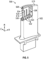
- FIG. 5 a schematic illustration of an airfoil 500 in accordance with an embodiment of the present disclosure are shown.
- FIG. 5 illustrates an airfoil body 502 after a manufacturing process using a core assembly, such as shown and described with respect to FIG. 4 , prior to formation of a squealer pocket with a cavity purge slot 526 formed for connecting to the squealer pocket.
- the airfoil body 502 includes a plurality of internal cavities formed therein, which may be formed by removal of core assembly material after casting of the airfoil body 502, as will be appreciated by those of skill in the art.
- the airfoil body 502 includes a leading edge cavity 530, a pressure side cavity 532, a suction side cavity 534, and a trailing edge cavity 536.
- the pressure side cavity 532 may be a serpentine flow cavity that is fluidly connected to the leading edge cavity 530 through one or more impingement holes, as will be appreciated by those of skill in the art.
- the suction side cavity 534 may comprise a set of one or more radially extending channels that may be separated by radially extending ribs 538.
- the radially extending ribs 538 may extend between a core rib 540 that separates the pressure side cavity 532 from the suction side cavity 534 and a suction side 518 of the airfoil body 502.
- the suction side cavity 534 is formed with a cavity purge slot 526 that extends in a radial direction R toward the tip 510.
- the suction side cavity 534 includes a portion (the cavity purge slot 526) that extends radially closer to the tip 510 than the rest of the suction side cavity 534 (or other internal cavities of the airfoil body 502).
- a portion of the airfoil body 502 may be further treated or worked to form additional features on the airfoil 500.
- an EDM process can use an electrode to cut into and remove material of the airfoil body 502 from the tip 510.
- the EDM process may be used to remove material from the tip 510 to form a squealer pocket therein (e.g., as shown in FIGS. 3A-3B ).
- the electrode of the EDM process cuts into the material of the airfoil 500 a portion of the material at the cavity purge slot 526 may be exposed, thus forming the cavity purge slot 526 which fluidly connects the suction side cavity 534 with the squealer pocket.
- FIGS. 6A-6C schematic illustrations of part of a manufacturing process for forming an airfoil 600 in accordance with an embodiment of the present disclosure are shown.
- the airfoil 600 may be similar to that shown and described above, and may be formed using a core assembly, as described above.
- the airfoil 600 includes a tip 610, a pressure side 616, a suction side 618, an internal pressure side cavity 632, and an internal suction side cavity 634.
- the pressure side cavity 632 is separated from the suction side cavity 634 by a core rib 640 that extends from a base to a tip of the airfoil 600.
- FIG. 6A illustrates the airfoil 600 prior to formation of a squealer pocket 620 (shown in FIG. 6C ).
- the suction side cavity 634 includes a cavity extension 642 that extends closer (radially) to the tip 610 than the rest of the suction side cavity 634 (and closer to the tip 610 than the radial extent of the pressure side cavity 632).
- FIG. 6B illustrates an electrode 670 extending into the material of the airfoil 600 to remove material at the tip 610 to form the squealer pocket 620 (e.g., cutting the material of the airfoil 600).
- the electrode 670 is sized and shaped to form the squealer pocket 620 having a pocket base 622 extending between the pressure side 616 and the suction side 618 at a depth below the tip 610.
- the suction side cavity 634 is fluidly connected to the squealer pocket 620 through a cavity purge slot 628 (formerly the cavity extension 642), as shown in FIG. 6C .
- the pressure side cavity 632 may be fluidly connected to the squealer pocket 620 through one or more cavity purge holes formed using rods (not shown), as described above.
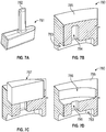
- FIGS. 7A-7D schematic illustrations of parts of a manufacturing process of an airfoil 780 in accordance with an embodiment of the present disclosure are shown.
- the airfoil 780 is formed using a single core structure 781 having a purge slot protrusion 782 (shown in FIG. 7A ).
- the core structure 781 of this embodiment may be arranged to form a conventional internal airfoil cooling cavity 783 (i.e., extending between two hot external walls, i.e., pressure side and suction side). That is, a single, relatively thin airfoil 780 may be formed with the single internal cooling cavity 783 defined therein, based on the core structure 781 shown in FIG. 7A .
- the core structure 781 is used for casting material of the formed airfoil 780, and thus formation of a cavity extension 784 is formed by the purge slot protrusion 782.
- This configuration may be employed because a width (or other dimensions) of the core structure 781 may be too small to accommodate the use of rods for forming purge holes.
- the airfoil 780 is formed, after casting and removal of the core structure 781, with a tip 785. It may be desirable to form a squealer pocket 786 (shown in FIG. 7D ) in order to allow for desired cooling flow exiting from the internal cooling cavity 783 into a hot gas path during operation.
- an electrode 787 may be used after casting of the airfoil 780.
- the electrode 787 may be sized and shaped to remove material at the tip 785 of the airfoil 780 such that the squealer pocket 786 may be formed in the tip 785 of the airfoil 780.
- a connection with the cavity extension 784 may be formed.
- the electrode 787 may cut or remove material of the airfoil to expose the cavity extension 784 to form a cavity purge slot 790 (shown formed in FIG. 7D ) that provides for fluid communication from the internal cavity 783 and the squealer pocket 786.
- a cavity purge slot (as compared to cavity purge holes) may be used for any cavity of an airfoil, and is not limited to suction side cavities and/or single internal cavities.
- similar purge slot protrusions may be formed on any given core structure or portion thereof to allow for a cavity purge slot to be formed.
- a pressure side cavity may include a purge slot protrusion at a location that may be too thin to accommodate a purge hole rod.
- a leading edge core structure and/or trailing edge core structure may include such protrusions, if a tip purge is desired for such cavities.
- the electrode used in EDM processes described herein can be made up of multiple pieces or can be a monolithic electrode having the required geometry.
- the specific location of the core (purge slot) protrusions and cavity extensions may be selected to form a cavity purge slot at a desired location and having desired features (e.g., dimensions, geometry, etc.) to provide appropriate purging capability for a given cavity.
- the core (purge slot) protrusions described herein, used to form cavity purge slots may be employed on core structures having minimum dimensions that are insufficient to support rods and/or allow for drilling to form purge holes, as typically done for relatively larger core structures and formed cavities.
- the core protrusions may be used on core structures having a smallest dimension, at the location of the desired purging, of about 0.075 inches (1.905 mm) or less. Typically, such dimension will be in a circumferential direction (i.e., a direction between a pressure side and suction side of a formed airfoil).
- core protrusions may be used on hybrid skin cores (i.e., cores used to form skin core cavities having a hot side defined by an external hot wall of an airfoil and an internal cold wall).
- hybrid skin cores i.e., cores used to form skin core cavities having a hot side defined by an external hot wall of an airfoil and an internal cold wall.
- an external hot wall of an airfoil is an external surface that is exposed to a gaspath during operation
- an internal cold wall refers to an internal structure of an airfoil that is not exposed directly to hot gaspath air during operation.
- FIG. 8 a flow process 800 for manufacturing an airfoil in accordance with an embodiment of the present disclosure is shown.
- the flow process 800 may be employed to form an airfoil as shown and described above, or other airfoil configurations that include one or more cores/internal cavities that are too small, narrow, or otherwise dimensioned such that a rod or drilling operation may not be employed to form a cavity purge hole.
- a core assembly is formed with at least one core structure having a purge slot protrusion.
- the core assembly can include one or more core structures.
- a single core structure may be employed to form an airfoil having a single internal cooling cavity.
- multiple core structures will be formed and arranged to form multiple different (separate or connected) internal cavities of an airfoil.
- one or more core structures of a core assembly may include such purge slot protrusions.
- a single core structure of a core assembly can include multiple purge slot protrusions if desired, and depending on the configuration of the airfoil and internal cooling scheme thereof.
- an airfoil body is formed around the core assembly.
- the formation of the airfoil body about the core assembly may be by casting, as will be appreciated by those of skill in the art.
- the core assembly is removed from the formed airfoil body to form one or more internal cavities.
- At least one internal cavity will include a cavity extension at the location of the purge slot protrusion.
- the removal process may be done by known means and mechanisms.
- an operation is performed to form a squealer pocket at the tip of the airfoil body.
- a cut or removal of material at the tip of the firmed airfoil may be performed thus exposing the formed cavity extension.
- a cavity purge slot may be formed that fluidly connects the internal cavity to the squealer pocket at the location of the cavity extension.
- the process may be an electrical discharge machining ("EDM”) process although other manufacturing processes may be employed without departing from the scope of the present disclosure.
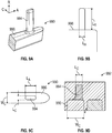
- FIGS. 9A-9D schematic illustrations of a core structure 990 in accordance with an embodiment of the present disclosure are shown.
- FIG. 9A is an isometric illustration of the core structure 990 used to form an airfoil body 992 (shown in FIG. 9D ) and having a purge slot protrusion 994.
- FIG. 9B is a side elevation illustration of the core structure 990.
- FIG. 9C is a top-down plan view illustration of the core structure 990.
- FIG. 9D is a schematic illustration of the core structure 990 within the airfoil body 992 prior to removal of the core structure 990 during a manufacturing process.
- the purge slot protrusion 994 that is part of the core structure 990 has a radial length L R that is defined as height or distance of extension from a top 996 of the core structure 990.
- the purge slot protrusion 994 has an axial length or width L A .
- the purge slot protrusion 994 has a circumferential length or width L C (i.e., pressure side to suction side of a formed airfoil, as described above) which is narrower than a circumferential length or width Wc of the core structure 990 (as shown in FIGS. 9C-9D ).
- FIG. 9D illustrates the core structure 990 as arranged within a formed (e.g., cast) airfoil body 992 around the core structure 990.
- the purge slot protrusion 994 extends upward (i.e., the radial direction) beyond the extent of the main body of the core structure 990, and enables formation of a cavity purge slot, as described above.
- the purge slot protrusion may have specific dimensions to enable formation of the desired purge slot without impacting the manufacturing and/or producibility of parts as discussed herein.
- the purge slot protrusion may have a width (i.e., pressure side to suction side direction) that does not exceed the width of the core from which the purge slot protrusion extends (in the same direction).
- the width of the purge slot protrusion in the circumferential direction discussed above, is not larger than the width of the core from which it extends, in the circumferential direction.
- a cross sectional area of the purge slot protrusion may define the purge slot size.
- the circumferential width may be equal to or greater than 0.014 inches (0.356 mm) and the axial length may be equal to or greater than 0.014 inches (0.356 mm).
- a height i.e., radial direction; i.e., the length of extension from a core
- circumferential thickness ratio does not to exceed 5:1.
- embodiments described herein allow for purge mechanisms of internal cavities of airfoils that cannot be formed using traditional mechanisms (e.g., rods, drilling, etc.).
- core structures are formed with extensions at a portion of the core structure to enable the formation of a cavity extension within a formed airfoil.
- the formed cavity extension provides for a thinner material portion at the location thereof, thus enabling cutting or removal of such thinner material and the formation of a purge slot, as shown and described above.
- the term "about” is intended to include the degree of error associated with measurement of the particular quantity based upon the equipment available at the time of filing the application. For example, “about” may include a range of ⁇ 8%, or 5%, or 2% of a given value or other percentage change as will be appreciated by those of skill in the art for the particular measurement and/or dimensions referred to herein.
Landscapes
- Engineering & Computer Science (AREA)
- Mechanical Engineering (AREA)
- General Engineering & Computer Science (AREA)
- Turbine Rotor Nozzle Sealing (AREA)
- Molds, Cores, And Manufacturing Methods Thereof (AREA)
Priority Applications (1)
| Application Number | Priority Date | Filing Date | Title |
|---|---|---|---|
| EP23161268.0A EP4215721A1 (fr) | 2019-06-26 | 2020-06-26 | Ensemble profil aérodynamique et noyau pour moteur à turbine à gaz |
Applications Claiming Priority (2)
| Application Number | Priority Date | Filing Date | Title |
|---|---|---|---|
| US16/453,101 US11041395B2 (en) | 2019-06-26 | 2019-06-26 | Airfoils and core assemblies for gas turbine engines and methods of manufacture |
| US16/593,076 US11053803B2 (en) | 2019-06-26 | 2019-10-04 | Airfoils and core assemblies for gas turbine engines and methods of manufacture |
Related Child Applications (1)
| Application Number | Title | Priority Date | Filing Date |
|---|---|---|---|
| EP23161268.0A Division EP4215721A1 (fr) | 2019-06-26 | 2020-06-26 | Ensemble profil aérodynamique et noyau pour moteur à turbine à gaz |
Publications (3)
| Publication Number | Publication Date |
|---|---|
| EP3757352A2 true EP3757352A2 (fr) | 2020-12-30 |
| EP3757352A3 EP3757352A3 (fr) | 2021-01-13 |
| EP3757352B1 EP3757352B1 (fr) | 2023-03-15 |
Family
ID=71170395
Family Applications (2)
| Application Number | Title | Priority Date | Filing Date |
|---|---|---|---|
| EP23161268.0A Pending EP4215721A1 (fr) | 2019-06-26 | 2020-06-26 | Ensemble profil aérodynamique et noyau pour moteur à turbine à gaz |
| EP20182444.8A Active EP3757352B1 (fr) | 2019-06-26 | 2020-06-26 | Procédé de fabrication d'un profil d'aube avec cavités internes |
Family Applications Before (1)
| Application Number | Title | Priority Date | Filing Date |
|---|---|---|---|
| EP23161268.0A Pending EP4215721A1 (fr) | 2019-06-26 | 2020-06-26 | Ensemble profil aérodynamique et noyau pour moteur à turbine à gaz |
Country Status (2)
| Country | Link |
|---|---|
| US (1) | US11053803B2 (fr) |
| EP (2) | EP4215721A1 (fr) |
Cited By (1)
| Publication number | Priority date | Publication date | Assignee | Title |
|---|---|---|---|---|
| FR3130881A1 (fr) * | 2021-12-20 | 2023-06-23 | Safran Aircraft Engines | Aube comportant un trou de dépoussiérage comportant une portion d’admission étendue |
Families Citing this family (5)
| Publication number | Priority date | Publication date | Assignee | Title |
|---|---|---|---|---|
| US11255199B2 (en) * | 2020-05-20 | 2022-02-22 | Rolls-Royce Corporation | Airfoil with shaped mass reduction pocket |
| US11725520B2 (en) | 2021-11-04 | 2023-08-15 | Rolls-Royce Corporation | Fan rotor for airfoil damping |
| US11746659B2 (en) | 2021-12-23 | 2023-09-05 | Rolls-Royce North American Technologies Inc. | Fan blade with internal shear-thickening fluid damping |
| US11560801B1 (en) | 2021-12-23 | 2023-01-24 | Rolls-Royce North American Technologies Inc. | Fan blade with internal magnetorheological fluid damping |
| US20240301799A1 (en) * | 2023-03-07 | 2024-09-12 | Raytheon Technologies Corporation | Airfoil tip arrangement for gas turbine engine |
Family Cites Families (24)
| Publication number | Priority date | Publication date | Assignee | Title |
|---|---|---|---|---|
| US6257831B1 (en) | 1999-10-22 | 2001-07-10 | Pratt & Whitney Canada Corp. | Cast airfoil structure with openings which do not require plugging |
| US7739162B1 (en) * | 2001-05-04 | 2010-06-15 | West Corporation | System, method, and business method for setting micropayment transaction to a pre-paid instrument |
| US6974308B2 (en) * | 2001-11-14 | 2005-12-13 | Honeywell International, Inc. | High effectiveness cooled turbine vane or blade |
| US7108045B2 (en) | 2004-09-09 | 2006-09-19 | United Technologies Corporation | Composite core for use in precision investment casting |
| US7377747B2 (en) | 2005-06-06 | 2008-05-27 | General Electric Company | Turbine airfoil with integrated impingement and serpentine cooling circuit |
| GB0524735D0 (en) | 2005-12-03 | 2006-01-11 | Rolls Royce Plc | Turbine blade |
| US7695243B2 (en) | 2006-07-27 | 2010-04-13 | General Electric Company | Dust hole dome blade |
| US7610946B2 (en) | 2007-01-05 | 2009-11-03 | Honeywell International Inc. | Cooled turbine blade cast tip recess |
| US8186965B2 (en) | 2009-05-27 | 2012-05-29 | General Electric Company | Recovery tip turbine blade |
| FR2986982B1 (fr) | 2012-02-22 | 2024-07-05 | Snecma | Ensemble de noyau de fonderie pour la fabrication d'une aube de turbomachine, procede de fabrication d'une aube et aube associes |
| US9429027B2 (en) | 2012-04-05 | 2016-08-30 | United Technologies Corporation | Turbine airfoil tip shelf and squealer pocket cooling |
| US9279331B2 (en) * | 2012-04-23 | 2016-03-08 | United Technologies Corporation | Gas turbine engine airfoil with dirt purge feature and core for making same |
| US10376998B2 (en) | 2014-07-03 | 2019-08-13 | United Technologies Corporation | Methods and tools for use in repairing gas engine turbine blades |
| FR3030333B1 (fr) | 2014-12-17 | 2017-01-20 | Snecma | Procede de fabrication d'une aube de turbomachine comportant un sommet pourvu d'une baignoire de type complexe |
| FR3037829B1 (fr) | 2015-06-29 | 2017-07-21 | Snecma | Noyau pour le moulage d'une aube ayant des cavites superposees et comprenant un trou de depoussierage traversant une cavite de part en part |
| US10253637B2 (en) | 2015-12-11 | 2019-04-09 | General Electric Company | Method and system for improving turbine blade performance |
| FR3047767B1 (fr) | 2016-02-12 | 2019-05-31 | Safran | Procede de formation de trous de depoussierage pour aube de turbine et noyau ceramique associe |
| FR3048374B1 (fr) | 2016-03-01 | 2018-04-06 | Snecma | Noyau pour le moulage d'une aube ayant des cavites superposees et comprenant un conduit de depoussierage traversant une cavite de part en part |
| US10801331B2 (en) | 2016-06-07 | 2020-10-13 | Raytheon Technologies Corporation | Gas turbine engine rotor including squealer tip pocket |
| EP3301261B1 (fr) * | 2016-09-14 | 2019-07-17 | Rolls-Royce plc | Aube |
| WO2018143997A1 (fr) | 2017-02-03 | 2018-08-09 | Siemens Aktiengesellschaft | Pale de turbine |
| US10533428B2 (en) * | 2017-06-05 | 2020-01-14 | United Technologies Corporation | Oblong purge holes |
| FR3072415B1 (fr) | 2017-10-17 | 2020-11-06 | Safran Aircraft Engines | Aube de turbine creuse a prelevement d'air de refroidissement reduit |
| US11041395B2 (en) * | 2019-06-26 | 2021-06-22 | Raytheon Technologies Corporation | Airfoils and core assemblies for gas turbine engines and methods of manufacture |
-
2019
- 2019-10-04 US US16/593,076 patent/US11053803B2/en active Active
-
2020
- 2020-06-26 EP EP23161268.0A patent/EP4215721A1/fr active Pending
- 2020-06-26 EP EP20182444.8A patent/EP3757352B1/fr active Active
Cited By (1)
| Publication number | Priority date | Publication date | Assignee | Title |
|---|---|---|---|---|
| FR3130881A1 (fr) * | 2021-12-20 | 2023-06-23 | Safran Aircraft Engines | Aube comportant un trou de dépoussiérage comportant une portion d’admission étendue |
Also Published As
| Publication number | Publication date |
|---|---|
| EP3757352B1 (fr) | 2023-03-15 |
| EP3757352A3 (fr) | 2021-01-13 |
| EP4215721A1 (fr) | 2023-07-26 |
| US20210062658A1 (en) | 2021-03-04 |
| US11053803B2 (en) | 2021-07-06 |
Similar Documents
| Publication | Publication Date | Title |
|---|---|---|
| EP3757352B1 (fr) | Procédé de fabrication d'un profil d'aube avec cavités internes | |
| EP3505726B1 (fr) | Ensemble d'aube pour moteur de turbine à gaz | |
| EP3044418B1 (fr) | Aube de moteur à turbine à gaz avec système de refroidissement à déflecteur à double arceau | |
| EP3399145A2 (fr) | Cavités hybrides de bord d'attaque et noyaux pour aubes de moteur de turbine à gaz | |
| EP3453832A1 (fr) | Composants de moteur de section chaude ayant des orifices de décharge d'espace de segment | |
| EP3757351B1 (fr) | Procédé de fabrication d'une aube | |
| EP3444435B1 (fr) | Joint de dilatation pour surface portante pour moteur à turbine à gaz | |
| US20190330986A1 (en) | Platform cover plates for gas turbine engine components | |
| EP3564485B1 (fr) | Surfaces portantes, noyaux et procédés de fabrication pour former des surfaces portantes comprenant des circuits de refroidissement de plate-formes reliées de manière fluidique | |
| EP3708778B1 (fr) | Inserts pour rotor à aubage intégral à fentes | |
| EP3567219B1 (fr) | Profil aérodynamique pour moteur à turbine à gaz | |
| US10941663B2 (en) | Airfoil having improved leading edge cooling scheme and damage resistance | |
| US11168571B2 (en) | Airfoil having dead-end tip flag cavity | |
| EP3663517B1 (fr) | Composant pour moteur à turbine à gaz et moteur à turbine à gaz associé | |
| EP3748133B1 (fr) | Joint à air extérieur d'aube résistant à la fatigue | |
| EP3564486B1 (fr) | Profil aérodynamique ayant un schéma de refroidissement amélioré | |
| EP3708776A1 (fr) | Profil d'aubes d'une turbine à gaz dotées d'une cavité dans le bout d'aube conique et noyaux de formation de celles-ci | |
| EP3613949B1 (fr) | Profil aérodynamique présentant un schéma de refroidissement par flux amélioré et une meilleure résistance aux dommages | |
| EP3550110B1 (fr) | Profil aérodynamique ayant un schéma de refroidissement de bord d'attaque à compensation de frappe arrière |
Legal Events
| Date | Code | Title | Description |
|---|---|---|---|
| PUAI | Public reference made under article 153(3) epc to a published international application that has entered the european phase |
Free format text: ORIGINAL CODE: 0009012 |
|
| STAA | Information on the status of an ep patent application or granted ep patent |
Free format text: STATUS: THE APPLICATION HAS BEEN PUBLISHED |
|
| PUAL | Search report despatched |
Free format text: ORIGINAL CODE: 0009013 |
|
| AK | Designated contracting states |
Kind code of ref document: A2 Designated state(s): AL AT BE BG CH CY CZ DE DK EE ES FI FR GB GR HR HU IE IS IT LI LT LU LV MC MK MT NL NO PL PT RO RS SE SI SK SM TR |
|
| AX | Request for extension of the european patent |
Extension state: BA ME |
|
| AK | Designated contracting states |
Kind code of ref document: A3 Designated state(s): AL AT BE BG CH CY CZ DE DK EE ES FI FR GB GR HR HU IE IS IT LI LT LU LV MC MK MT NL NO PL PT RO RS SE SI SK SM TR |
|
| AX | Request for extension of the european patent |
Extension state: BA ME |
|
| RIC1 | Information provided on ipc code assigned before grant |
Ipc: B22C 9/10 20060101ALI20201207BHEP Ipc: F01D 5/20 20060101AFI20201207BHEP |
|
| STAA | Information on the status of an ep patent application or granted ep patent |
Free format text: STATUS: REQUEST FOR EXAMINATION WAS MADE |
|
| 17P | Request for examination filed |
Effective date: 20210712 |
|
| RBV | Designated contracting states (corrected) |
Designated state(s): AL AT BE BG CH CY CZ DE DK EE ES FI FR GB GR HR HU IE IS IT LI LT LU LV MC MK MT NL NO PL PT RO RS SE SI SK SM TR |
|
| INTG | Intention to grant announced |
Effective date: 20220921 |
|
| GRAS | Grant fee paid |
Free format text: ORIGINAL CODE: EPIDOSNIGR3 |
|
| STAA | Information on the status of an ep patent application or granted ep patent |
Free format text: STATUS: GRANT OF PATENT IS INTENDED |
|
| GRAA | (expected) grant |
Free format text: ORIGINAL CODE: 0009210 |
|
| STAA | Information on the status of an ep patent application or granted ep patent |
Free format text: STATUS: THE PATENT HAS BEEN GRANTED |
|
| AK | Designated contracting states |
Kind code of ref document: B1 Designated state(s): AL AT BE BG CH CY CZ DE DK EE ES FI FR GB GR HR HU IE IS IT LI LT LU LV MC MK MT NL NO PL PT RO RS SE SI SK SM TR |
|
| REG | Reference to a national code |
Ref country code: CH Ref legal event code: EP Ref country code: GB Ref legal event code: FG4D |
|
| REG | Reference to a national code |
Ref country code: DE Ref legal event code: R096 Ref document number: 602020008818 Country of ref document: DE |
|
| REG | Reference to a national code |
Ref country code: IE Ref legal event code: FG4D |
|
| REG | Reference to a national code |
Ref country code: AT Ref legal event code: REF Ref document number: 1554120 Country of ref document: AT Kind code of ref document: T Effective date: 20230415 |
|
| P01 | Opt-out of the competence of the unified patent court (upc) registered |
Effective date: 20230521 |
|
| REG | Reference to a national code |
Ref country code: LT Ref legal event code: MG9D |
|
| REG | Reference to a national code |
Ref country code: NL Ref legal event code: MP Effective date: 20230315 |
|
| PG25 | Lapsed in a contracting state [announced via postgrant information from national office to epo] |
Ref country code: RS Free format text: LAPSE BECAUSE OF FAILURE TO SUBMIT A TRANSLATION OF THE DESCRIPTION OR TO PAY THE FEE WITHIN THE PRESCRIBED TIME-LIMIT Effective date: 20230315 Ref country code: NO Free format text: LAPSE BECAUSE OF FAILURE TO SUBMIT A TRANSLATION OF THE DESCRIPTION OR TO PAY THE FEE WITHIN THE PRESCRIBED TIME-LIMIT Effective date: 20230615 Ref country code: LV Free format text: LAPSE BECAUSE OF FAILURE TO SUBMIT A TRANSLATION OF THE DESCRIPTION OR TO PAY THE FEE WITHIN THE PRESCRIBED TIME-LIMIT Effective date: 20230315 Ref country code: LT Free format text: LAPSE BECAUSE OF FAILURE TO SUBMIT A TRANSLATION OF THE DESCRIPTION OR TO PAY THE FEE WITHIN THE PRESCRIBED TIME-LIMIT Effective date: 20230315 Ref country code: HR Free format text: LAPSE BECAUSE OF FAILURE TO SUBMIT A TRANSLATION OF THE DESCRIPTION OR TO PAY THE FEE WITHIN THE PRESCRIBED TIME-LIMIT Effective date: 20230315 |
|
| REG | Reference to a national code |
Ref country code: AT Ref legal event code: MK05 Ref document number: 1554120 Country of ref document: AT Kind code of ref document: T Effective date: 20230315 |
|
| PG25 | Lapsed in a contracting state [announced via postgrant information from national office to epo] |
Ref country code: SE Free format text: LAPSE BECAUSE OF FAILURE TO SUBMIT A TRANSLATION OF THE DESCRIPTION OR TO PAY THE FEE WITHIN THE PRESCRIBED TIME-LIMIT Effective date: 20230315 Ref country code: NL Free format text: LAPSE BECAUSE OF FAILURE TO SUBMIT A TRANSLATION OF THE DESCRIPTION OR TO PAY THE FEE WITHIN THE PRESCRIBED TIME-LIMIT Effective date: 20230315 Ref country code: GR Free format text: LAPSE BECAUSE OF FAILURE TO SUBMIT A TRANSLATION OF THE DESCRIPTION OR TO PAY THE FEE WITHIN THE PRESCRIBED TIME-LIMIT Effective date: 20230616 Ref country code: FI Free format text: LAPSE BECAUSE OF FAILURE TO SUBMIT A TRANSLATION OF THE DESCRIPTION OR TO PAY THE FEE WITHIN THE PRESCRIBED TIME-LIMIT Effective date: 20230315 |
|
| PG25 | Lapsed in a contracting state [announced via postgrant information from national office to epo] |
Ref country code: SM Free format text: LAPSE BECAUSE OF FAILURE TO SUBMIT A TRANSLATION OF THE DESCRIPTION OR TO PAY THE FEE WITHIN THE PRESCRIBED TIME-LIMIT Effective date: 20230315 Ref country code: RO Free format text: LAPSE BECAUSE OF FAILURE TO SUBMIT A TRANSLATION OF THE DESCRIPTION OR TO PAY THE FEE WITHIN THE PRESCRIBED TIME-LIMIT Effective date: 20230315 Ref country code: PT Free format text: LAPSE BECAUSE OF FAILURE TO SUBMIT A TRANSLATION OF THE DESCRIPTION OR TO PAY THE FEE WITHIN THE PRESCRIBED TIME-LIMIT Effective date: 20230717 Ref country code: ES Free format text: LAPSE BECAUSE OF FAILURE TO SUBMIT A TRANSLATION OF THE DESCRIPTION OR TO PAY THE FEE WITHIN THE PRESCRIBED TIME-LIMIT Effective date: 20230315 Ref country code: EE Free format text: LAPSE BECAUSE OF FAILURE TO SUBMIT A TRANSLATION OF THE DESCRIPTION OR TO PAY THE FEE WITHIN THE PRESCRIBED TIME-LIMIT Effective date: 20230315 Ref country code: CZ Free format text: LAPSE BECAUSE OF FAILURE TO SUBMIT A TRANSLATION OF THE DESCRIPTION OR TO PAY THE FEE WITHIN THE PRESCRIBED TIME-LIMIT Effective date: 20230315 Ref country code: AT Free format text: LAPSE BECAUSE OF FAILURE TO SUBMIT A TRANSLATION OF THE DESCRIPTION OR TO PAY THE FEE WITHIN THE PRESCRIBED TIME-LIMIT Effective date: 20230315 |
|
| RAP4 | Party data changed (patent owner data changed or rights of a patent transferred) |
Owner name: RTX CORPORATION |
|
| PG25 | Lapsed in a contracting state [announced via postgrant information from national office to epo] |
Ref country code: SK Free format text: LAPSE BECAUSE OF FAILURE TO SUBMIT A TRANSLATION OF THE DESCRIPTION OR TO PAY THE FEE WITHIN THE PRESCRIBED TIME-LIMIT Effective date: 20230315 Ref country code: PL Free format text: LAPSE BECAUSE OF FAILURE TO SUBMIT A TRANSLATION OF THE DESCRIPTION OR TO PAY THE FEE WITHIN THE PRESCRIBED TIME-LIMIT Effective date: 20230315 Ref country code: IS Free format text: LAPSE BECAUSE OF FAILURE TO SUBMIT A TRANSLATION OF THE DESCRIPTION OR TO PAY THE FEE WITHIN THE PRESCRIBED TIME-LIMIT Effective date: 20230715 |
|
| REG | Reference to a national code |
Ref country code: DE Ref legal event code: R097 Ref document number: 602020008818 Country of ref document: DE |
|
| PG25 | Lapsed in a contracting state [announced via postgrant information from national office to epo] |
Ref country code: MC Free format text: LAPSE BECAUSE OF FAILURE TO SUBMIT A TRANSLATION OF THE DESCRIPTION OR TO PAY THE FEE WITHIN THE PRESCRIBED TIME-LIMIT Effective date: 20230315 |
|
| PLBE | No opposition filed within time limit |
Free format text: ORIGINAL CODE: 0009261 |
|
| STAA | Information on the status of an ep patent application or granted ep patent |
Free format text: STATUS: NO OPPOSITION FILED WITHIN TIME LIMIT |
|
| PG25 | Lapsed in a contracting state [announced via postgrant information from national office to epo] |
Ref country code: SI Free format text: LAPSE BECAUSE OF FAILURE TO SUBMIT A TRANSLATION OF THE DESCRIPTION OR TO PAY THE FEE WITHIN THE PRESCRIBED TIME-LIMIT Effective date: 20230315 Ref country code: MC Free format text: LAPSE BECAUSE OF FAILURE TO SUBMIT A TRANSLATION OF THE DESCRIPTION OR TO PAY THE FEE WITHIN THE PRESCRIBED TIME-LIMIT Effective date: 20230315 Ref country code: DK Free format text: LAPSE BECAUSE OF FAILURE TO SUBMIT A TRANSLATION OF THE DESCRIPTION OR TO PAY THE FEE WITHIN THE PRESCRIBED TIME-LIMIT Effective date: 20230315 |
|
| REG | Reference to a national code |
Ref country code: CH Ref legal event code: PL |
|
| 26N | No opposition filed |
Effective date: 20231218 |
|
| REG | Reference to a national code |
Ref country code: BE Ref legal event code: MM Effective date: 20230630 |
|
| PG25 | Lapsed in a contracting state [announced via postgrant information from national office to epo] |
Ref country code: LU Free format text: LAPSE BECAUSE OF NON-PAYMENT OF DUE FEES Effective date: 20230626 |
|
| REG | Reference to a national code |
Ref country code: IE Ref legal event code: MM4A |
|
| PG25 | Lapsed in a contracting state [announced via postgrant information from national office to epo] |
Ref country code: LU Free format text: LAPSE BECAUSE OF NON-PAYMENT OF DUE FEES Effective date: 20230626 |
|
| PG25 | Lapsed in a contracting state [announced via postgrant information from national office to epo] |
Ref country code: IE Free format text: LAPSE BECAUSE OF NON-PAYMENT OF DUE FEES Effective date: 20230626 |
|
| PG25 | Lapsed in a contracting state [announced via postgrant information from national office to epo] |
Ref country code: IE Free format text: LAPSE BECAUSE OF NON-PAYMENT OF DUE FEES Effective date: 20230626 Ref country code: CH Free format text: LAPSE BECAUSE OF NON-PAYMENT OF DUE FEES Effective date: 20230630 |
|
| PG25 | Lapsed in a contracting state [announced via postgrant information from national office to epo] |
Ref country code: IT Free format text: LAPSE BECAUSE OF FAILURE TO SUBMIT A TRANSLATION OF THE DESCRIPTION OR TO PAY THE FEE WITHIN THE PRESCRIBED TIME-LIMIT Effective date: 20230315 Ref country code: BE Free format text: LAPSE BECAUSE OF NON-PAYMENT OF DUE FEES Effective date: 20230630 |
|
| PG25 | Lapsed in a contracting state [announced via postgrant information from national office to epo] |
Ref country code: BG Free format text: LAPSE BECAUSE OF FAILURE TO SUBMIT A TRANSLATION OF THE DESCRIPTION OR TO PAY THE FEE WITHIN THE PRESCRIBED TIME-LIMIT Effective date: 20230315 |
|
| PG25 | Lapsed in a contracting state [announced via postgrant information from national office to epo] |
Ref country code: BG Free format text: LAPSE BECAUSE OF FAILURE TO SUBMIT A TRANSLATION OF THE DESCRIPTION OR TO PAY THE FEE WITHIN THE PRESCRIBED TIME-LIMIT Effective date: 20230315 |
|
| PG25 | Lapsed in a contracting state [announced via postgrant information from national office to epo] |
Ref country code: CY Free format text: LAPSE BECAUSE OF FAILURE TO SUBMIT A TRANSLATION OF THE DESCRIPTION OR TO PAY THE FEE WITHIN THE PRESCRIBED TIME-LIMIT; INVALID AB INITIO Effective date: 20200626 |
|
| PG25 | Lapsed in a contracting state [announced via postgrant information from national office to epo] |
Ref country code: HU Free format text: LAPSE BECAUSE OF FAILURE TO SUBMIT A TRANSLATION OF THE DESCRIPTION OR TO PAY THE FEE WITHIN THE PRESCRIBED TIME-LIMIT; INVALID AB INITIO Effective date: 20200626 |
|
| REG | Reference to a national code |
Ref country code: DE Ref legal event code: R081 Ref document number: 602020008818 Country of ref document: DE Owner name: RTX CORPORATION (N.D.GES.D. STAATES DELAWARE),, US Free format text: FORMER OWNER: RAYTHEON TECHNOLOGIES CORPORATION, FARMINGTON, CT, US |
|
| PG25 | Lapsed in a contracting state [announced via postgrant information from national office to epo] |
Ref country code: TR Free format text: LAPSE BECAUSE OF FAILURE TO SUBMIT A TRANSLATION OF THE DESCRIPTION OR TO PAY THE FEE WITHIN THE PRESCRIBED TIME-LIMIT Effective date: 20230315 |
|
| PGFP | Annual fee paid to national office [announced via postgrant information from national office to epo] |
Ref country code: GB Payment date: 20260520 Year of fee payment: 7 |
|
| PGFP | Annual fee paid to national office [announced via postgrant information from national office to epo] |
Ref country code: DE Payment date: 20260520 Year of fee payment: 7 |
|
| PGFP | Annual fee paid to national office [announced via postgrant information from national office to epo] |
Ref country code: FR Payment date: 20260520 Year of fee payment: 7 |