EP3757408A1 - Logement de boulon - Google Patents
Logement de boulon Download PDFInfo
- Publication number
- EP3757408A1 EP3757408A1 EP20175132.8A EP20175132A EP3757408A1 EP 3757408 A1 EP3757408 A1 EP 3757408A1 EP 20175132 A EP20175132 A EP 20175132A EP 3757408 A1 EP3757408 A1 EP 3757408A1
- Authority
- EP
- European Patent Office
- Prior art keywords
- bolt
- bolt receptacle
- receptacle according
- teeth
- sawtooth profile
- Prior art date
- Legal status (The legal status is an assumption and is not a legal conclusion. Google has not performed a legal analysis and makes no representation as to the accuracy of the status listed.)
- Withdrawn
Links
- 238000003780 insertion Methods 0.000 claims description 72
- 230000037431 insertion Effects 0.000 claims description 72
- 230000000694 effects Effects 0.000 description 3
- 238000001746 injection moulding Methods 0.000 description 3
- 239000000463 material Substances 0.000 description 3
- 239000007787 solid Substances 0.000 description 3
- 210000001520 comb Anatomy 0.000 description 1
- 230000006835 compression Effects 0.000 description 1
- 238000007906 compression Methods 0.000 description 1
- 238000010276 construction Methods 0.000 description 1
- 230000002349 favourable effect Effects 0.000 description 1
- 239000012530 fluid Substances 0.000 description 1
- 230000007774 longterm Effects 0.000 description 1
- NJPPVKZQTLUDBO-UHFFFAOYSA-N novaluron Chemical compound C1=C(Cl)C(OC(F)(F)C(OC(F)(F)F)F)=CC=C1NC(=O)NC(=O)C1=C(F)C=CC=C1F NJPPVKZQTLUDBO-UHFFFAOYSA-N 0.000 description 1
Images


Classifications
-
- F—MECHANICAL ENGINEERING; LIGHTING; HEATING; WEAPONS; BLASTING
- F16—ENGINEERING ELEMENTS AND UNITS; GENERAL MEASURES FOR PRODUCING AND MAINTAINING EFFECTIVE FUNCTIONING OF MACHINES OR INSTALLATIONS; THERMAL INSULATION IN GENERAL
- F16B—DEVICES FOR FASTENING OR SECURING CONSTRUCTIONAL ELEMENTS OR MACHINE PARTS TOGETHER, e.g. NAILS, BOLTS, CIRCLIPS, CLAMPS, CLIPS OR WEDGES; JOINTS OR JOINTING
- F16B37/00—Nuts or like thread-engaging members
- F16B37/08—Quickly-detachable or mountable nuts, e.g. consisting of two or more parts; Nuts movable along the bolt after tilting the nut
- F16B37/0807—Nuts engaged from the end of the bolt, e.g. axially slidable nuts
- F16B37/0857—Nuts engaged from the end of the bolt, e.g. axially slidable nuts with the threaded portions of the nut engaging the thread of the bolt by the action of one or more springs or resilient retaining members
-
- F—MECHANICAL ENGINEERING; LIGHTING; HEATING; WEAPONS; BLASTING
- F16—ENGINEERING ELEMENTS AND UNITS; GENERAL MEASURES FOR PRODUCING AND MAINTAINING EFFECTIVE FUNCTIONING OF MACHINES OR INSTALLATIONS; THERMAL INSULATION IN GENERAL
- F16B—DEVICES FOR FASTENING OR SECURING CONSTRUCTIONAL ELEMENTS OR MACHINE PARTS TOGETHER, e.g. NAILS, BOLTS, CIRCLIPS, CLAMPS, CLIPS OR WEDGES; JOINTS OR JOINTING
- F16B5/00—Joining sheets or plates, e.g. panels, to one another or to strips or bars parallel to them
- F16B5/02—Joining sheets or plates, e.g. panels, to one another or to strips or bars parallel to them by means of fastening members using screw-thread
- F16B5/0208—Joining sheets or plates, e.g. panels, to one another or to strips or bars parallel to them by means of fastening members using screw-thread using panel fasteners, i.e. permanent attachments allowing for quick assembly
Definitions
- the invention relates to a pin receptacle according to the preamble of claim 1.
- bolts have been developed, in particular, which are welded, glued, riveted or otherwise fastened to the body and then protrude from a body sheet.
- bolt receptacles are available.
- the bolts are rod-shaped bodies which are provided with a thread in the manner of a screw and to which something can be screwed.
- Bolt receptacles have the advantage over screws that they are not screwed on, but pushed on.
- bolt receptacles have corresponding holding devices which are supported on the threads of the bolt.
- the object of the invention is to create a bolt receptacle for mounting on bolts, such as vehicle bolts or aircraft bolts, which enables a reliable connection to the bolt with high tear-off forces and improved durability.
- the object is achieved with a bolt receptacle with the features of claim 1.
- the bolt receptacle according to the invention has at least one massive wall on which a sawtooth profile is formed, which is suitable for engaging the threads of a bolt.
- the retaining arm Opposite the solid wall and thus also opposite the sawtooth profile there is a flexible retaining arm which is biased towards the solid wall with a force or which is spaced from the wall at a distance that is less than the diameter of a bolt. Facing the sawtooth profile, the retaining arm is also profiled in such a way that it engages with profile sections in the thread turns of the bolt.
- the bolt receptacle according to the invention has at least one insertion opening through which a bolt can get into the area between the sawtooth profile and the retaining arm.
- Guide tabs are preferably formed on both sides of the sawtooth profile on the solid wall, which ensure lateral guidance of the bolt so that it cannot get out of the area of the sawtooth profile and the retaining arm.
- These guide tabs can be arranged offset to one another in relation to the insertion direction of the bolt, which makes it possible to produce the bolt receptacle in one piece in a simple manner, for example in injection molding tools, from a uniform material.
- Bottom side i.e. formed adjacent to the insertion opening and on a base plate of the bolt receptacle, there is at least one leaf spring element which is arranged bulged to the outside or to an underside of the base plate and rests on the surface to which the bolt is attached after the insertion of a bolt and a Exerts force that is directed against the direction of insertion of the bolt.
- a predefined pull-out force is permanently applied to the bolt receptacle, which leads to the retaining arm being pulled more strongly into the threads of the bolt and thereby also pushing the bolt into the sawtooth profile of the opposite wall and thereby the high pull-out forces that can occur from outside , ensures.
- the advantage of the invention is that a bolt receptacle is created which can be produced in a simple and cost-effective manner and at the same time ensures a very high level of connection security also in the long term.
- the tear-off forces are higher than in known constructions, although the bolt receptacle can also be unscrewed from the bolt to loosen the connection.
- the invention relates in particular to a bolt receptacle for locking reception and attachment to a bolt, the bolt receptacle having at least two latching means for locking the bolt in place, a first latching means being a sawtooth profile with at least one tooth, which is fixedly arranged and a second latching means is a
- the retaining arm is arranged diametrically opposite the first latching means with respect to a longitudinal axis of a bolt and is articulated in such a way that it is arranged to be pivotable laterally towards and away from the first latching means.
- the advantage here is that reliable fixing is achieved with a simple structure. It can be advantageous if the first locking means has one or more teeth, the profile extending along the insertion direction with teeth following one another in the insertion direction.
- the second latching means facing the first latching means, can have at least one engagement means for engaging a counter-engagement means of the bolt.
- the teeth of the sawtooth profile have a spacing from one another which essentially corresponds to the spacing of the thread crests of a bolt to be inserted.
- the distances between the apices of the engagement projections essentially corresponds to the distance between the thread crests or is adapted to this.
- the distance between the teeth on the one hand and the distance between the engagement projections on the other hand and the position of the engagement projections in relation to the teeth on the other hand in the locked state can be arranged in such a way that both the teeth with their tooth edges on the one hand and the engagement projections with their apices on the other hand into the threads a bolt to be inserted are arranged to be engaged.
- the teeth can have a long flank and a short steep flank, the long flank initially extending up to a tooth edge in the insertion direction extends laterally into a receiving space for a bolt and then a short flank follows, which has a steeper slope in the insertion direction.
- the bolt receptacle has at least one base plate and a first side wall oriented orthogonally to this, the sawtooth profile being formed on the side wall and an insertion opening being arranged in the base plate.
- the retaining arm prefferably be arranged laterally pivotable adjacent to the base plate and to extend laterally and elastically pivotably towards the sawtooth profile in the insertion direction.
- a cover plate opposite the base plate, with a through-opening for the bolt to be inserted being present in the cover plate in alignment with the base plate.
- the sawtooth profile with its teeth and / or the retaining arm with at least one engagement projection can advantageously protrude into the axial alignment between the insertion opening and the insertion opening.
- guide tabs are arranged laterally next to the sawtooth profile, which laterally delimit the push-through path of the bolt from the insertion opening into the bolt receptacle and / or to the push-through opening.
- one or more guide tabs are axially offset from one another in the insertion direction and are arranged alternately with respect to the sides of the sawtooth profile.
- the insertion tab is arranged adjacent to the insertion opening and / or the insertion opening in order to guide a bolt to be inserted during insertion and / or insertion.
- the bolt receptacle in the present example is essentially box-like with a bottom wall, a top wall and four side walls connecting these walls.
- the bolt receptacle can also be round, polygonal, oval or have some other external spatial shape, as long as the functional parts to be described are functional in their arrangement to one another available.
- the external three-dimensional shape of the bolt receptacle can be determined by its task, in particular if the bolt receptacle is an integral part of a component that has other functions, for example a cable or line receptacle or the like.
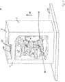
- a bolt receptacle 1 according to the invention is in a first exemplary embodiment ( Figures 1 - 9 ) an essentially box-like arrangement with a base plate 2, a top plate 3 and two opposing first side walls 4, 5 and, perpendicular to this, two opposing second side walls 6, 7.
- a receiving space 8 is formed between the first side walls and second side walls 4, 5; 6, 7, a receiving space 8 is formed.
- An opening is provided in each of the base plate 2 and the cover plate 3, with an insertion opening 9 in the base plate 2 and a push-through opening 10 in the cover plate for a bolt 12 to be received.
- the insertion opening 9 in the base plate 2 and the insertion opening 10 in the top plate 3 are aligned with one another and have a diameter that is preferably slightly wider than the diameter of a bolt 12 to be inserted in order to insert the bolt in the insertion opening and the insertion opening during insertion to allow lateral play.
- a sawtooth profile 15 protruding into the receiving space 8 with teeth 14 is arranged on the inner surface 13 of a first side wall 4 facing the receiving space 8.
- the sawtooth profile 15 extends in the insertion direction 11 between the insertion opening 9 and the insertion opening 10.
- the teeth 14 are formed with long flat flanks 16 and short steep flanks 17, the resulting common tooth edge 18 being formed transversely to the insertion direction 11.
- the teeth 14 protrude into the receiving space 8 between the insertion opening 9 and the insertion opening 10.
- a retaining arm 20 is arranged in the area of the opposite first side wall 5 or its inner side 19, a retaining arm 20 is arranged.
- the restraint arm is in a lower, i.e. the area 21 closer to the base plate 2 with a film hinge 23 on an inner surface 19 of the wall 5 and / or an elevation 22, which protrudes like a platform into the receiving space 8 from the base plate 2, while a free end 24 in the receiving space 8 and in particular protrudes into the alignment between the insertion opening 9 and the insertion opening 10.
- the retaining arm 20 has the sawtooth profile 15 and thus the first side wall 4 or its inner surface 13 facing, at least one engagement projection 25, but in particular a plurality of engagement projections 25, which are rounded tooth-like or wave-shaped in cross section.
- the distance between the apex of the engagement projections 25 on the one hand and the distance between the edges 18 of the teeth 14 on the other hand preferably corresponds to the distance between the threads of a bolt with thread or the distance between the tooth bases in a profile bolt with circumferential teeth.
- a first guide tab 26 protrudes from an inner surface of the base plate adjacent to the sawtooth profile and can in particular also be arranged at a corner on the inner surface 13 of the first side wall 4.
- a second guide tab 27 protrudes from an inner 28 of the ceiling wall or ceiling plate 3 laterally next to the sawtooth profile 15 into the receiving space and can also be connected to the inner surface 13 of the first side wall 4 at a corner.
- third guide tabs 28 on different sides of the sawtooth profile 15, offset from one another in relation to the insertion direction 11, can be formed protruding from the inner surface 13 into the receiving space 8.
- the guide tabs 26, 27, 28, in particular four guide tabs, can thus be arranged alternately with respect to the insertion direction 11 and can be arranged in a side view with or without overlap.
- the outer three-dimensional shape of the embodiment described is only exemplary and not essential; any three-dimensional shape is suitable which enables the functional elements described and, above all, the sawtooth profile 15 and the opposing retaining arm 20, which is diametrically opposite along an aligned axis of the Insertion opening 9 and through opening 10 are arranged, can perform their task.
- the walls 6 and 7 are formed with perforations towards the receiving space 8, such a shape also not being essential, but rather, in particular in the case of injection molding processes, it serves to form the functional elements in the interior.
- the retaining arm 20 it is only essential that it protrudes into the receiving space 28 and is articulated in such a way that it can be deflected by the threads of a bolt 12 when a bolt 12 is inserted and by its articulation on the main body of the Bolt receptacle 1 swivels into the threads of a bolt 12.
- the bolt receptacle rests with a base plate 2 on a carrier plate 31 or a carrier element 31 on which the bolt is attached protruding from it.
- the engagement projections 25 of the retaining arm 20 are preferably designed so that there is a long edge in the insertion direction, followed by the apex of the engagement projection and then a steeper edge.
- the bolt braces this movement, on the one hand, on the short flanks 17 of the sawtooth profile 15 and, on the other hand, on the steep flanks of the engagement projections 25, whereby the retaining arm 20 also pushes or pushes even more into the threads 29 is pulled and thereby also presses the bolt into the sawtooth profile 15.
- a pull-out movement thus strengthens the locking or connection between the bolt receptacle 1 and the bolt 12.
- the bolt 12 When fully inserted, the bolt 12 is laterally bounded by the guide tabs 26, 27 and 28 and protrudes with a free end 32 into the push-through opening 10 or passes through it .
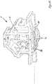
- FIG. 10-12 shows the arrangement according to the invention in a different three-dimensional shape, with the bolt holder 1 being cut out of an overall structure in the illustration, whereby the overall structure can for example have functional areas present on the bolt holder 1, such as receiving or fixing areas for cables, lines or the like ( Not shown).
- the basic elements sawtooth profile 15 and retaining arm 20 are designed in the same way, and guide tabs 26-28 are also present, as of course also an insertion opening 9 and a push-through opening 10.
- webs or runners 35 are formed on the underside of a base plate 2, the webs or runners 35 each being arranged approximately at the level of the walls 4, 5 or being arranged slightly offset thereto.
- leaf spring elements 36 which bulge out against the insertion direction 11 beyond the runners 35.
- leaf springs 36 all possible other spring elements are also suitable as long as they produce a compression spring effect away from the base plate 2.
- a first side wall 4 is formed which extends in the insertion direction from a base plate 2 to a top plate 3.
- the second side wall 5 here does not have a planar three-dimensional shape, but rather a three-dimensional shape that is predetermined by another function, but the retaining arm 20 is designed in the same way as compared to the sawtooth profile 15.
- the mode of operation is identical to the first embodiment, in contrast to the first embodiment, when inserting the bolt 12, the leaf spring elements 36 touch a carrier element 31 of the bolt 12 before the runners 35 and against their spring force between the runners 36 are pressed. As a result, an additional pull-out force is exerted against the insertion direction 11 when the bolt 12 is fully inserted, so that the elastic restoring force of the hinge 23 of the retaining arm 20 also has a locking effect on the spring force of the leaf spring elements 36.
- additional support elements or spring elements can be present, in particular in the area of the functional components attached to the bolt receptacle 1, which is not shown.
- the leaf springs 36 can also only be arranged between columns or stub-like elements.
- the bolt receptacle 1 is formed in particular from a plastic, in particular from a plastic that can be molded using an injection molding process, so that in particular the hinge 23 of the retaining arm 20 is formed as a film hinge made of the material.
- a plastic in particular from a plastic that can be molded using an injection molding process, so that in particular the hinge 23 of the retaining arm 20 is formed as a film hinge made of the material.
- this does not exclude the possibility that the bolt receptacle is also made from different materials.
- the advantage of the invention is that an easy-to-install bolt receptacle is created which provides a secure connection between the bolt receptacle and a bolt and thus the secure arrangement of functional components and the bolt on a carrier element allows, the bolt receptacle according to the invention can be produced in a simple manner and has a high level of functional reliability and assembly capability.
- the bolt receptacle has a simple and effective structure in that two latching elements are arranged in the bolt receptacle, interacting with the bolt thread in a latching manner, one latching element being fixed and the other latching element being arranged laterally movable, the laterally movable one when the bolt is inserted
- Latching element can evade during insertion and the latching elements are designed in such a way that laterally movable latching element is drawn into the thread when the bolt is moved against the pull-out direction, thereby reducing the space between the latching elements, so that secure latching is ensured.
Landscapes
- Engineering & Computer Science (AREA)
- General Engineering & Computer Science (AREA)
- Mechanical Engineering (AREA)
- Connection Of Plates (AREA)
Applications Claiming Priority (1)
| Application Number | Priority Date | Filing Date | Title |
|---|---|---|---|
| DE102019117232.2A DE102019117232A1 (de) | 2019-06-26 | 2019-06-26 | Bolzenaufnahme |
Publications (1)
| Publication Number | Publication Date |
|---|---|
| EP3757408A1 true EP3757408A1 (fr) | 2020-12-30 |
Family
ID=70968711
Family Applications (1)
| Application Number | Title | Priority Date | Filing Date |
|---|---|---|---|
| EP20175132.8A Withdrawn EP3757408A1 (fr) | 2019-06-26 | 2020-05-18 | Logement de boulon |
Country Status (2)
| Country | Link |
|---|---|
| EP (1) | EP3757408A1 (fr) |
| DE (1) | DE102019117232A1 (fr) |
Cited By (1)
| Publication number | Priority date | Publication date | Assignee | Title |
|---|---|---|---|---|
| WO2025091906A1 (fr) * | 2023-10-31 | 2025-05-08 | 深圳市乐其网络科技有限公司 | Ensemble de verrouillage, tête de trépied et dispositif de support |
Citations (5)
| Publication number | Priority date | Publication date | Assignee | Title |
|---|---|---|---|---|
| US4840333A (en) * | 1987-09-21 | 1989-06-20 | Nifco, Inc. | Device for fastening bar-like objects |
| EP1069326A2 (fr) * | 1999-07-14 | 2001-01-17 | A. Raymond & Cie | Elément de fixation amovible sur un goujon cannelé en plastique |
| US20050095082A1 (en) * | 2003-10-30 | 2005-05-05 | Newfrey Llc | Fasteners for attaching pipes to a support |
| DE202012008730U1 (de) * | 2012-09-12 | 2013-12-13 | Newfrey Llc | Befestigungseinrichtung |
| DE102014103651A1 (de) * | 2014-03-18 | 2015-09-24 | Newfrey Llc | Clip aus Kunststoff zur Befestigung eines Gegenstands an einem Bolzen |
Family Cites Families (3)
| Publication number | Priority date | Publication date | Assignee | Title |
|---|---|---|---|---|
| SE455435B (sv) * | 1982-10-15 | 1988-07-11 | Usm Corp | Plastklemma for infestning av ett ror vid en fran en yta utskjutande tapp |
| DE3903342A1 (de) * | 1989-02-04 | 1990-08-09 | Georg Bunz | Steckverschluss fuer schmuckteile |
| DE9011441U1 (de) * | 1990-08-06 | 1990-11-15 | Emhart Inc., Newark, Del. | Vorrichtung zur Befestigung zweier Bauteile |
-
2019
- 2019-06-26 DE DE102019117232.2A patent/DE102019117232A1/de not_active Withdrawn
-
2020
- 2020-05-18 EP EP20175132.8A patent/EP3757408A1/fr not_active Withdrawn
Patent Citations (5)
| Publication number | Priority date | Publication date | Assignee | Title |
|---|---|---|---|---|
| US4840333A (en) * | 1987-09-21 | 1989-06-20 | Nifco, Inc. | Device for fastening bar-like objects |
| EP1069326A2 (fr) * | 1999-07-14 | 2001-01-17 | A. Raymond & Cie | Elément de fixation amovible sur un goujon cannelé en plastique |
| US20050095082A1 (en) * | 2003-10-30 | 2005-05-05 | Newfrey Llc | Fasteners for attaching pipes to a support |
| DE202012008730U1 (de) * | 2012-09-12 | 2013-12-13 | Newfrey Llc | Befestigungseinrichtung |
| DE102014103651A1 (de) * | 2014-03-18 | 2015-09-24 | Newfrey Llc | Clip aus Kunststoff zur Befestigung eines Gegenstands an einem Bolzen |
Cited By (1)
| Publication number | Priority date | Publication date | Assignee | Title |
|---|---|---|---|---|
| WO2025091906A1 (fr) * | 2023-10-31 | 2025-05-08 | 深圳市乐其网络科技有限公司 | Ensemble de verrouillage, tête de trépied et dispositif de support |
Also Published As
| Publication number | Publication date |
|---|---|
| DE102019117232A1 (de) | 2020-12-31 |
Similar Documents
| Publication | Publication Date | Title |
|---|---|---|
| EP0615071B1 (fr) | Elément de raccordement en matière plastique | |
| DE3902499C2 (fr) | ||
| DE19646988C5 (de) | Beschlag für ein Fenster | |
| EP2642894B1 (fr) | Dispositif de fixation pour parties de paroi | |
| DE69605148T2 (de) | Aufprallenergieabsorbierende Struktur in einer Fahrzeug-Sicherheitsgurtvorrichtung | |
| EP1177387A1 (fr) | Element d'assemblage | |
| EP3276186B1 (fr) | Bouchon à vis | |
| DE19545069A1 (de) | Stoßstange mit Querträger in Halbschalenbauweise | |
| DE102020120766A1 (de) | Befestigungseinrichtung, Verfahren, Anordnung und Schaltschrank | |
| EP0293614B1 (fr) | Boîte d'installation électrique dans des parois creuses, notamment pour interrupteurs, prises de courant et choses similaires | |
| DE29914145U1 (de) | Gegenschließteil, insbesondere für einen Drehfallenverschluß | |
| DE102007015129B3 (de) | Nicht demontierbarer Clip aus Kunststoff | |
| DE3942774C2 (de) | Gehäuse für Verschlüsse, Stellhebel, Durchführungen od. dgl., zur Montage in einem Durchbruch in einer dünnen, elektrisch leitenden Wand, wie Blechschranktür oder Maschinengehäusedeckel | |
| EP3757408A1 (fr) | Logement de boulon | |
| DE2609473C3 (de) | Elektrisches Installationsgerät (Signalleuchte, Schaltgerät u.dgl.) zum Einbau in eine öffnung einer Trägerplatte | |
| DE102005037074B4 (de) | Scheinwerferverstellsystem | |
| EP0754827A2 (fr) | Dispositif pour la fixation amovible et axialement non coulissante d'une poignée sur un élément de palier, notamment pour une poignée de porte ou fenêtre | |
| EP0843064A2 (fr) | Ferrure pour un fenêtre | |
| DE102018206849B4 (de) | Vorrichtung zur klemmenden Befestigung | |
| DE102017116057B4 (de) | Befestigungsbaugruppe | |
| DE202010004995U1 (de) | Befestiger zur Befestigung eines ersten Bauteils an einem zweiten Bauteil | |
| DE102015120559B3 (de) | Montageelement zur Befestigung von Türbändern | |
| EP1134170A1 (fr) | Structure à assemblage modulaire pour des rayons de stockage | |
| EP4193434A1 (fr) | Dispositif de fixation, procédé, agencement et armoire de distribution | |
| EP0063294B1 (fr) | Dispositif de fixation, en particulier pour accoudoir ou poignées à la paroi intérieure de carosserie pour véhicules |
Legal Events
| Date | Code | Title | Description |
|---|---|---|---|
| PUAI | Public reference made under article 153(3) epc to a published international application that has entered the european phase |
Free format text: ORIGINAL CODE: 0009012 |
|
| STAA | Information on the status of an ep patent application or granted ep patent |
Free format text: STATUS: THE APPLICATION HAS BEEN PUBLISHED |
|
| AK | Designated contracting states |
Kind code of ref document: A1 Designated state(s): AL AT BE BG CH CY CZ DE DK EE ES FI FR GB GR HR HU IE IS IT LI LT LU LV MC MK MT NL NO PL PT RO RS SE SI SK SM TR |
|
| AX | Request for extension of the european patent |
Extension state: BA ME |
|
| STAA | Information on the status of an ep patent application or granted ep patent |
Free format text: STATUS: REQUEST FOR EXAMINATION WAS MADE |
|
| 17P | Request for examination filed |
Effective date: 20210625 |
|
| RBV | Designated contracting states (corrected) |
Designated state(s): AL AT BE BG CH CY CZ DE DK EE ES FI FR GB GR HR HU IE IS IT LI LT LU LV MC MK MT NL NO PL PT RO RS SE SI SK SM TR |
|
| STAA | Information on the status of an ep patent application or granted ep patent |
Free format text: STATUS: EXAMINATION IS IN PROGRESS |
|
| 17Q | First examination report despatched |
Effective date: 20230208 |
|
| STAA | Information on the status of an ep patent application or granted ep patent |
Free format text: STATUS: THE APPLICATION IS DEEMED TO BE WITHDRAWN |
|
| 18D | Application deemed to be withdrawn |
Effective date: 20230819 |