EP3758191A2 - Procédé et appareil de réglage de position de bobine d`un emetteur dans une transmission d`energie sans fil - Google Patents
Procédé et appareil de réglage de position de bobine d`un emetteur dans une transmission d`energie sans fil Download PDFInfo
- Publication number
- EP3758191A2 EP3758191A2 EP20171824.4A EP20171824A EP3758191A2 EP 3758191 A2 EP3758191 A2 EP 3758191A2 EP 20171824 A EP20171824 A EP 20171824A EP 3758191 A2 EP3758191 A2 EP 3758191A2
- Authority
- EP
- European Patent Office
- Prior art keywords
- magnetic field
- transmitting coil
- indication information
- power
- parameter
- Prior art date
- Legal status (The legal status is an assumption and is not a legal conclusion. Google has not performed a legal analysis and makes no representation as to the accuracy of the status listed.)
- Pending
Links
Images




Classifications
-
- H—ELECTRICITY
- H02—GENERATION; CONVERSION OR DISTRIBUTION OF ELECTRIC POWER
- H02J—ELECTRIC POWER NETWORKS; CIRCUIT ARRANGEMENTS OR SYSTEMS FOR SUPPLYING OR DISTRIBUTING ELECTRIC POWER; SYSTEMS FOR STORING ELECTRIC ENERGY
- H02J50/00—Circuit arrangements or systems for wireless supply or distribution of electric power
- H02J50/10—Circuit arrangements or systems for wireless supply or distribution of electric power using inductive coupling
-
- H—ELECTRICITY
- H01—ELECTRIC ELEMENTS
- H01F—MAGNETS; INDUCTANCES; TRANSFORMERS; SELECTION OF MATERIALS FOR THEIR MAGNETIC PROPERTIES
- H01F27/00—Details of transformers or inductances, in general
- H01F27/34—Special means for preventing or reducing unwanted electric or magnetic effects, e.g. no-load losses, reactive currents, harmonics, oscillations, leakage fields
- H01F27/36—Electric or magnetic shields or screens
-
- H—ELECTRICITY
- H01—ELECTRIC ELEMENTS
- H01F—MAGNETS; INDUCTANCES; TRANSFORMERS; SELECTION OF MATERIALS FOR THEIR MAGNETIC PROPERTIES
- H01F38/00—Adaptations of transformers or inductances for specific applications or functions
- H01F38/14—Inductive couplings
-
- H—ELECTRICITY
- H02—GENERATION; CONVERSION OR DISTRIBUTION OF ELECTRIC POWER
- H02J—ELECTRIC POWER NETWORKS; CIRCUIT ARRANGEMENTS OR SYSTEMS FOR SUPPLYING OR DISTRIBUTING ELECTRIC POWER; SYSTEMS FOR STORING ELECTRIC ENERGY
- H02J50/00—Circuit arrangements or systems for wireless supply or distribution of electric power
- H02J50/70—Circuit arrangements or systems for wireless supply or distribution of electric power involving the reduction of electric, magnetic or electromagnetic leakage fields
-
- H—ELECTRICITY
- H02—GENERATION; CONVERSION OR DISTRIBUTION OF ELECTRIC POWER
- H02J—ELECTRIC POWER NETWORKS; CIRCUIT ARRANGEMENTS OR SYSTEMS FOR SUPPLYING OR DISTRIBUTING ELECTRIC POWER; SYSTEMS FOR STORING ELECTRIC ENERGY
- H02J50/00—Circuit arrangements or systems for wireless supply or distribution of electric power
- H02J50/90—Circuit arrangements or systems for wireless supply or distribution of electric power involving detection or optimisation of position, e.g. alignment
-
- H—ELECTRICITY
- H02—GENERATION; CONVERSION OR DISTRIBUTION OF ELECTRIC POWER
- H02J—ELECTRIC POWER NETWORKS; CIRCUIT ARRANGEMENTS OR SYSTEMS FOR SUPPLYING OR DISTRIBUTING ELECTRIC POWER; SYSTEMS FOR STORING ELECTRIC ENERGY
- H02J50/00—Circuit arrangements or systems for wireless supply or distribution of electric power
- H02J50/80—Circuit arrangements or systems for wireless supply or distribution of electric power involving the exchange of data, concerning supply or distribution of electric power, between transmitting devices and receiving devices
-
- H—ELECTRICITY
- H02—GENERATION; CONVERSION OR DISTRIBUTION OF ELECTRIC POWER
- H02J—ELECTRIC POWER NETWORKS; CIRCUIT ARRANGEMENTS OR SYSTEMS FOR SUPPLYING OR DISTRIBUTING ELECTRIC POWER; SYSTEMS FOR STORING ELECTRIC ENERGY
- H02J7/00—Circuit arrangements for charging or discharging batteries or for supplying loads from batteries
- H02J7/02—Circuit arrangements for charging or discharging batteries or for supplying loads from batteries for charging batteries from AC mains by converters
-
- Y—GENERAL TAGGING OF NEW TECHNOLOGICAL DEVELOPMENTS; GENERAL TAGGING OF CROSS-SECTIONAL TECHNOLOGIES SPANNING OVER SEVERAL SECTIONS OF THE IPC; TECHNICAL SUBJECTS COVERED BY FORMER USPC CROSS-REFERENCE ART COLLECTIONS [XRACs] AND DIGESTS
- Y02—TECHNOLOGIES OR APPLICATIONS FOR MITIGATION OR ADAPTATION AGAINST CLIMATE CHANGE
- Y02B—CLIMATE CHANGE MITIGATION TECHNOLOGIES RELATED TO BUILDINGS, e.g. HOUSING, HOUSE APPLIANCES OR RELATED END-USER APPLICATIONS
- Y02B40/00—Technologies aiming at improving the efficiency of home appliances, e.g. induction cooking or efficient technologies for refrigerators, freezers or dish washers
-
- Y—GENERAL TAGGING OF NEW TECHNOLOGICAL DEVELOPMENTS; GENERAL TAGGING OF CROSS-SECTIONAL TECHNOLOGIES SPANNING OVER SEVERAL SECTIONS OF THE IPC; TECHNICAL SUBJECTS COVERED BY FORMER USPC CROSS-REFERENCE ART COLLECTIONS [XRACs] AND DIGESTS
- Y02—TECHNOLOGIES OR APPLICATIONS FOR MITIGATION OR ADAPTATION AGAINST CLIMATE CHANGE
- Y02T—CLIMATE CHANGE MITIGATION TECHNOLOGIES RELATED TO TRANSPORTATION
- Y02T10/00—Road transport of goods or passengers
- Y02T10/60—Other road transportation technologies with climate change mitigation effect
- Y02T10/70—Energy storage systems for electromobility, e.g. batteries
-
- Y—GENERAL TAGGING OF NEW TECHNOLOGICAL DEVELOPMENTS; GENERAL TAGGING OF CROSS-SECTIONAL TECHNOLOGIES SPANNING OVER SEVERAL SECTIONS OF THE IPC; TECHNICAL SUBJECTS COVERED BY FORMER USPC CROSS-REFERENCE ART COLLECTIONS [XRACs] AND DIGESTS
- Y02—TECHNOLOGIES OR APPLICATIONS FOR MITIGATION OR ADAPTATION AGAINST CLIMATE CHANGE
- Y02T—CLIMATE CHANGE MITIGATION TECHNOLOGIES RELATED TO TRANSPORTATION
- Y02T10/00—Road transport of goods or passengers
- Y02T10/60—Other road transportation technologies with climate change mitigation effect
- Y02T10/7072—Electromobility specific charging systems or methods for batteries, ultracapacitors, supercapacitors or double-layer capacitors
Definitions
- Wireless charging technology is a charging technology that uses the principle of electromagnetic induction, that is, electrical energy is transmitted by using an alternating magnetic field generated between coils.
- the wireless charging technology is exemplarily applied to a mobile phone.
- the mobile phone is placed on a wireless charging device, the wireless charging device is provided with a transmitting coil, and the mobile phone is provided with a receiving coil.
- the transmitting coil is powered on and generates a constantly varying magnetic field, and the receiving coil may sense variations of the magnetic field and generates a current which charges the battery of the mobile phone and implements wireless charging.
- Embodiments of the present invention relate to the technical field of wireless charging, and in particular, relate to a method and apparatus for adjusting a coil position.
- a method for adjusting a coil position is provided, which is applied to a power transmitting device.
- the method includes:
- a method for adjusting a coil position is provided, which is applied to a power receiving device.
- the method includes:
- an apparatus for adjusting a coil position which is applied to a power transmitting device, the apparatus comprising:
- an apparatus for adjusting a coil position which is applied to a power receiving device.
- the apparatus includes:
- the technical solutions according to the embodiments of the present invention may achieve the following beneficial effects:
- the coil position is adjusted by the power transmitting device adjusts according to the position offset between the transmitting coil and the receiving coil. If the power receiving device is not properly placed on the power transmitting device, the position of the transmitting coil is automatically adjusted, such that a geometric center of the transmitting coil coincides with or approaches that of the receiving coil as far as possible. In this way, the charging efficiency of the power receiving device is improved.
- FIG. 1 is a schematic diagram of a service scenario of wireless charging according to some embodiments of the present disclosure.
- the service scenario may include a power transmitting device 10 and a power receiving device 20.
- the power transmitting device 10 refers to a device configured to supply power to a power consuming device in a wireless charging system. In different service scenarios, the power transmitting device 10 may be named differently. For example, if the power transmitting device 10 is configured to wirelessly charge a portable electronic device such as a mobile phone, a tablet computer, a wearable device or the like, the power transmitting device 10 may be referred to as a charger, a charger pad, a power adapter, a wireless charger or the like.
- the power receiving device 20 refers to a device configured to receive power in wireless charging, that is, a power consuming device.
- the power receiving device 20 may be any power consuming device supporting wireless charging, for example, a terminal device such as a mobile phone, a tablet computer, a wearable device or the like, which is not limited in the embodiments of the present disclosure.
- the technical solutions according to the embodiments of the present disclosure are applicable to a scenario of wireless charging for a terminal device such as a mobile phone, a tablet computer, or a wearable device.
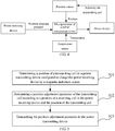
- FIG. 2 is a flowchart of a method for adjusting a coil position according to some embodiments of the present disclosure.
- the method can be applied to the power transmitting device 10 as described above.
- the method can include the following steps (steps 201 to 202).
- Step 201 position offset indication information between a transmitting coil in the power transmitting device and a receiving coil in a power receiving device is acquired.
- the power transmitting device is configured to wirelessly charge the power receiving device, and the position offset indication information is used to reflect a position offset between the transmitting coil and the receiving coil.
- the position offset indication information is used to reflect a position offset between the transmitting coil and the receiving coil.
- Step 202 a position of the transmitting coil is adjusted according to the position offset indication information.
- the power transmitting device is capable of adjusting the position of the transmitting coil, such that a geometric center of the transmitting coil coincides with or approaches that of the receiving coil as far as possible and thus improves the charging efficiency.
- a power device may be arranged in the power transmitting device, and the power device is configured to control the transmitting coil to move, for example, control the transmitting coil to move within a plane where the transmitting coil is located.
- the power device may be designed as follows. Electromagnets are arranged along X and Y directions of the transmitting coil in the power transmitting device, magnets or iron sheets or other magnetic material are arranged on the position of transmitting coil corresponding to the electromagnets for receiving forces generated by the electromagnets. By applying currents of different sizes to the electromagnets, forces of different sizes are generated between the electromagnets and the magnets. By applying the currents to different electromagnets, the transmitting coil may sense forces of different directions. By applying the currents of different sizes to the different electromagnets, a resultant force sensed by the transmitting coil is a position offset amount desired by the transmitting coil, such that the transmitting coil is aligned with the receiving coil.
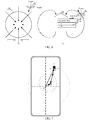
- FIG. 3 exemplarily illustrates a schematic diagram of position adjustment of a transmitting coil. Electromagnets 11 are arranged in the power transmitting device 10, and magnets 12 are arranged at positions corresponding to the electromagnets of the transmitting coil. As illustrated by the upper half in FIG. 3 , when the power receiving device 20 is placed, as illustrated in FIG. 3 , on the power transmitting device 10, the geometric center of the transmitting coil (the circle in broken line in FIG. 3 represents the transmitting coil) is not aligned with the geometric center of the receiving coil (the circle in solid line in FIG. 3 represents the receiving coil).
- the power transmitting device 10 determines that the transmitting coil is required to be adjusted by 2 mm to the left side according to the position offset indication information and then the power transmitting device 10 applies a corresponding current to the electromagnet 11 on the left side and applies no current to the electromagnets on the other three sides, such that an attraction force is generated between the electromagnet 11 on the left side and the transmitting coil, and the transmitting coil is moved to the left side by 2 mm.
- different currents may be applied to different electromagnets 11 as long as the final resultant force may cause the transmitting coil to move to the left until an effect as illustrated by the lower half in FIG. 3 is achieved.
- the coil position is adjusted by the power transmitting device according to the position offset between the transmitting coil and the receiving coil. If the power receiving device is not properly placed on the power transmitting device, the position of the transmitting coil is automatically adjusted, such that a geometric center of the transmitting coil coincides with or approaches that of the receiving coil as far as possible and thus improves the charging efficiency of the power receiving device.
- the position adjustment of the transmitting coil has the following two cases.
- the power transmitting device determines the position offset indication information by itself, and adaptively adjusts the position of the transmitting coil.
- the position offset indication information includes charging efficiency indication information.
- the charging efficiency indication information is used to indicate a charging efficiency of wireless charging.
- the charging efficiency indication information may be determined in the following approaches.
- the currently expected charging efficiency is used to indicate a charging efficiency when the receiving coil is aligned with the transmitting coil under a current electric quantity. Since the charging efficiencies are different when the receiving coil is aligned with the transmitting coil under different electric quantities, a mapping relationship exists between the electric quantity and the expected charging efficiency. Therefore, in a case that the power transmitting device knows the current electric quantity, the currently expected charging efficiency may be determined according to the mapping between the electric quantity and the expected charging efficiency.
- the position of the transmitting coil may be adjusted in the following approaches.
- the power transmitting device re-acquires the efficiency loss and in this case the efficiency loss is -4.5 which is less than -4 but greater than -5, and then it indicates that the adjustment direction of the transmitting coil is correct, and the power transmitting device may continue moving the transmitting coil to the left as long as the finally acquired efficiency is caused to be greater than -4. If the efficiency loss re-acquired by the power transmitting device is -6, which is less than -5, after the power transmitting device moves the transmitting coil to the left, it indicates that the adjustment direction of the transmitting coil is incorrect, and the transmitting coil needs to be moved to the right.
- the efficiency loss re-acquired by the power transmitting device is -4.5, which is greater than -6 and less than -4, after the power transmitting device moves the transmitting coil to the right, it indicates that the adjustment direction at this time is correct and the power transmitting device needs to continue moving the transmitting coil to the right until the re-acquired efficiency loss is greater than -4.
- the power transmitting device may re-acquire the charging efficiency indication information every a predetermined time period, and the step of detecting whether the charging efficiency indication information satisfies the first predetermined condition is performed again or the step of detecting whether the charging temperature indication information satisfies the second predetermined condition is performed again.
- the position offset indication information further includes charging temperature indication information.
- the charging temperature indication information is used to indicate a temperature of the power transmitting device.
- a temperature sensor is arranged in the power transmitting device.
- the current temperature may be determined by the temperature sensor.
- the currently expected temperature is used to indicate a temperature when the receiving coil is aligned with the transmitting coil under a current electric quantity. Since the temperatures are different when the receiving coil is aligned with the transmitting coil under different electric quantities, a mapping relationship exists between the electric quantity and the desired temperature. Therefore, in a case that the power transmitting device knows the current electric quantity, the currently expected temperature may be determined according to the mapping relationship between the electric quantity and the expected temperature.
- the position of the transmitting coil may be adjusted in the following approaches.
- the charging temperature indication information is the temperature loss
- the temperature loss takes a value of 10
- the third threshold is 5
- the temperature loss is greater than the third threshold, it indicates that the charging temperature indication information satisfies the second predetermined condition, and the power transmitting device needs to adjust the position of the transmitting coil.
- the efficiency loss is -5.
- the power transmitting device Assuming that the power transmitting device firstly moves the transmitting coil to the left, the power transmitting device re-acquires the efficiency loss, and in this case the efficiency loss is -4.5 which is less than -4 but greater than -5 and the temperature loss takes a value of 8.8 which is greater than 5 but less than 10, it indicates that the adjustment direction of the transmitting coil is correct, and the power transmitting device may continue moving the transmitting coil to the left as long as the finally acquired efficiency loss is greater than the first threshold and the finally acquired temperature loss is less than the third threshold.
- the temperature loss re-acquired by the power transmitting device is 12 which is greater than 10 after the power transmitting device moves the transmitting coil to the left, it indicates that the adjustment direction of the transmitting coil is incorrect, and the transmitting coil needs to be moved to the right. If the temperature loss re-acquired by the power transmitting device is 9 which is greater than 5 but less than 10 after the power transmitting device moves the transmitting coil to the right, it indicates that the adjustment direction of the transmitting coil is correct, and the power transmitting device needs to continue moving the transmitting coil to the right until the re-acquired efficiency loss is greater than -4 and the re-acquired temperature loss is less than 5.
- the power transmitting device may adjust the position of the transmitting coil until the charging temperature indication information does not satisfy the second predetermined condition, and the position adjustment of the transmitting coil is stopped.
- FIG. 4 exemplarily illustrates a schematic diagram of a closed-loop control system.
- the closed-loop control system includes a power receiving device, a microprocessor of a power transmitting device, a power device, a temperature sensor and a position sensor.
- the power receiving device transmits a current electric quantity and a received power to the microprocessor of the power transmitting device.
- the microprocessor determines the charging efficiency indication information according to the current electric quantity, the received power, and a transmitted power of the power transmitting device.
- the microprocessor determines charging temperature indication information according to the current electric quantity and a current temperature collected by the temperature sensor.
- the microprocessor detects whether the charging efficiency indication information satisfies a first predetermined condition, and whether the charging temperature indication information satisfies a second predetermined condition. If one of the predetermined conditions is satisfied, the microprocessor controls the power device to adjust the transmitting coil.
- the position sensor acquires a position of the adjusted transmitting coil, and transmits the position to the microprocessor.
- the microprocessor judges whether the adjusted transmitting coil satisfies a predetermined condition, and re-controls the power device to adjust the transmitting coil until the predetermined condition is not satisfied.
- the power receiving device transmits position offset indication information to the power transmitting device, and the power transmitting device adjust the position of the transmitting coil according to the position offset indication information transmitted by the power receiving device.
- the power receiving device transmits a position adjustment parameter to the power transmitting device, and the position adjustment parameter is used to indicate an adjustment direction and an adjustment distance of the transmitting coil.
- the process of determining the position adjustment parameter may be referenced to the embodiments hereinafter, which is not described herein any further.
- the power transmitting device receives the position adjustment parameter transmitted by the power receiving device.
- the position of the transmitting coil may be adjusted in the following approaches.
- the power transmitting device may adjust the position of the transmitting coil in two ways, and thus flexibility of the adjustment is high.
- the power transmitting device adaptively adjusts the position of the transmitting coil, and no additional resource device needs to be arranged in the power receiving device.
- the position of the transmitting coil is adjusted according to the position adjustment parameter transmitted by the power receiving device.
- the transmitting coil may be efficiently adjusted to a proper position according to the adjustment direction and the adjustment distance and less time is consumed.
- FIG. 5 is a flowchart of a method for adjusting a coil position according to another exemplary embodiment of the present disclosure.
- the method can be applied to the power receiving device 20 as described above.
- the method can include the following steps (steps 501 to 503).
- Step 501 a position of a transmitting coil in a power transmitting device configured to charge the power receiving device is determined by a magnetic induction sensor.
- the magnetic induction sensor refers to a device capable of extracting information from a magnetic field, which may convert a magnetic signal to an electrical signal.
- a magnetic induction sensor may be arranged in the power receiving device, and the magnetic induction sensor may be arranged on the main board of the power receiving device.
- the power receiving device may determine the position of the transmitting coil in the power transmitting device.
- Step 502 a position adjustment parameter of the transmitting coil is determined according to a position of a receiving coil in the power receiving device and the position of the transmitting coil.
- the position adjustment parameter is used to indicate an adjustment direction and an adjustment distance of the transmitting coil.
- a position adjustment parameter of the power transmitting device may be determined in combination with the position of the receiving coil in the power receiving device.
- the position adjustment parameter is used to adjust a relative position between the receiving coil and the transmitting coil to align the receiving coil with the transmitting coil.
- a relative position vector between the receiving coil and the transmitting coil may be directly calculated according to the position of the receiving coil and the position of the transmitting coil.
- the relative position vector includes a direction of the relative position and a distance of the relative position.
- the position adjustment parameter of the power receiving device may be determined according to the relative position vector between the receiving coil and the transmitting coil.
- the position adjustment parameter may be determined according to a first relative position vector between the receiving coil and the magnetic induction sensor, and a second relative position vector between the magnetic induction sensor and the transmitting coil.
- Step 503 the position adjustment parameter is transmitted to the power transmitting device.
- the power transmitting device receives the position adjustment parameter, and adjusts the position of the transmitting coil according to the position adjustment parameter.
- the position adjustment parameter of the transmitting coil is determined by the power receiving device according to the position of the receiving coil and the position of the transmitting coil, and the determined position parameter is transmitted to the power transmitting device, such that the power transmitting device adjusts the position of the transmitting coil according to the position adjustment parameter. In this way, adjustment of the position of the transmitting coil is quick and consumes less time.
- the position of the transmitting coil may be determined as follows.
- a magnetic field parameter of the magnet arranged in the power transmitting device is collected by the magnetic induction sensor.
- the power transmitting device may be provided with a magnet. By a magnetic field generated by the magnet, the relative position between the power receiving device and the power transmitting device may be further adjusted.
- the central position of the magnet is aligned with the central position of the transmitting coil.
- the magnet may be a circular magnet. In one aspect, when the magnet is a circular magnet, alignment of the central position with the central position of the transmitting coil is favorable to accurately determine the position of the transmitting coil. In another aspect, the circular magnet has a uniform magnetic field distribution, and thus facilitates the magnetic induction sensor to acquire the magnetic field parameter. In some other embodiments, the magnet may be in any other shapes, which is not limited in the embodiment of the present disclosure.
- the magnet may also be arranged above the transmitting coil, or may also be arranged below the transmitting coil, which is not limited in the embodiment of the present disclosure.
- the power transmission may further include an isolation magnetic sheet, which may be configured for magnetic conduction, magnetic block, heat conduction, or the like.
- the isolation magnetic sheet may be a hard magnetic sheet or a soft magnetic sheet.
- the magnetic sheet may be a ferrite sheet that is fabricated by high-temperature sintering and has a high magnetic permeability.
- the isolation magnetic sheet is a soft magnetic sheet
- the magnetic sheet may be a soft magnetic sheet fabricated by alloy magnetic powder, plastic, rubber or the like and has merits such as soft textures, small thickness, and high customization degree.
- a transmitting coil 30, an isolation magnetic sheet 40 and a magnet 50 are stacked in sequence from top to bottom, and centers of the transmitting coil 30, the isolation magnetic sheet 40 and the magnet 50 are on the same straight line.
- the position of the transmitting coil is determined according to the magnetic field parameter of the magnet.
- the magnetic field parameter of the magnet refers to a parameter relevant to the magnetic field generated by the magnet.
- the magnetic field parameter may include a magnetic field direction and a magnetic field magnitude.
- the magnetic field direction refers to a direction to which a magnetic induction line points
- the magnetic field magnitude refers to a magnetic field strength of the magnetic field.
- the position of the transmitting coil may be further determined according to the magnetic field parameter of the magnet.
- a magnetic field component in a horizontal direction of the magnet is determined according to the magnetic field parameter of the magnet.
- the magnetic field parameter of the magnet includes a magnetic field direction and a magnetic field magnitude.
- magnetic field components may be generated in different directions.
- panel (a) illustrates a schematic diagram of a magnetic field component on an XY plane (that is, the horizontal direction)
- panel (b) illustrates a schematic diagram of a magnetic field component in an Z axis.
- a magnet 50 is arranged below the transmitting coil 30 of the power transmitting device.
- a magnetic field generated by the magnet 50 may pass through a magnetic induction sensor 60 and magnetic field components are formed in an X axis, Y axis, and Z axis.
- the position of the transmitting coil is determined according to the magnetic field component and a first mapping relationship.
- the magnetic induction sensor When the magnetic induction sensor is away from the magnet in the power transmitting device, the magnetic induction sensor acquires a small magnetic field component; and when the magnetic induction sensor is close to the magnet in the power transmitting device, the magnetic induction sensor acquires a larger magnetic field component. Since the central position of the magnet is aligned with the central position of the transmitting coil in the power transmitting device, a certain mapping relationship exists between the magnetic field component and the position of the transmitting coil.
- the first mapping relationship is used to describe the mapping relationship between the magnetic field component and the position of the transmitting coil. In a case that the magnetic field component is determined, the position of the transmitting coil is determined according to the first mapping relationship.
- the first mapping relationship may be determined by the following steps.
- the power receiving device may acquire n different positions of the transmitting coil, and the magnetic induction sensor acquires different magnetic field components at different positions.
- a mapping relationship that is, the first mapping relationship, between the magnetic field component and the position of the transmitting coil may be obtained by fitting and according to the n positions and the magnetic field components corresponding to the n positions.
- the position of the transmitting coil may also be determined as follows.
- the magnetic field parameter of the transmitting coil is collected by the magnetic induction sensor.
- the magnetic induction sensor refers to a device capable of extracting information from a magnetic field, which is capable of converting a magnetic signal to an electrical signal.
- a magnetic induction sensor may be arranged in the power receiving device, and the magnetic induction sensor may be arranged on the main board of the power receiving device. By the magnetic induction sensor, the power receiving device may acquire the magnetic field parameter of the transmitting coil in the power transmitting device.
- a magnetic field parameter of a first magnetic field of the transmitting coil is collected by the magnetic induction sensor according to a first sampling frequency; and the magnetic field parameter of the transmitting coil is determined according to the magnetic field parameter of the first magnetic field collected by the sampling.
- the first magnetic field is a magnetic field generated by the transmitting coil for wireless charging, that is, a magnetic field of the transmitting coil when the transmitting coil wirelessly charges the power receiving device.
- the first magnetic field is also an alternating magnetic field.
- A represents an amplitude
- f represents a frequency of the alternating current in the transmitting coil
- t represents time
- ⁇ represents a phase angle
- the magnetic field parameters collected by the magnetic induction sensor may include all the magnetic field parameters of the first magnetic field of the transmitting coil, and by the collected magnetic field parameters, the magnetic field parameters of the first magnetic field of the transmitting coil may be restored.
- the above sampling theorem may also be referred to as Shannon sampling theorem or Nyquist sampling theorem. This sampling theorem indicates that when the sampling frequency is greater than or equal to twice of a maximum frequency of a valid signal, a sampling value may include all the information of the original signal and a sampled signal may be restored to the original signal without any distortion.
- the magnetic induction sensor acquires a plurality of magnetic field parameters of the first magnetic field of the transmitting coil according to the first sampling frequency, and further obtains, by fitting, a change curve of the magnetic field parameter of the first magnetic field with the time. According to the change curve, an amplitude (maximum value) of the magnetic field parameters of the first magnetic field may be collected, and thus the amplitude is determined as the magnetic field parameter of the transmitting coil.
- the amplitude from the plurality of magnetic field parameters may be directly determined as the magnetic field parameter of the transmitting coil.
- a magnetic field parameter of a second magnetic field of the transmitting coil is collected by the magnetic induction sensor according to a second sampling frequency, and the second magnetic field refers to another magnetic field generated by the transmitting coil in addition to the magnetic field used for wireless charging.
- the magnetic field parameter of the transmitting coil is determined according to the magnetic field parameter of the second magnetic field collected by sampling.
- the transmitting coil may generate another magnetic field, for example, a second magnetic field, in addition to the magnetic field for wireless charging.
- the second magnetic field is also an alternating magnetic field, and a variation frequency of the second magnetic field is lower than that of the first magnetic field.
- the magnetic induction sensor in the power receiving device may collect the magnetic field parameters of the second magnetic field of the transmitting coil according to the second sampling frequency.
- the second sampling frequency is greater than or equal to twice of the variation frequency of the second magnetic field.
- the magnetic induction sensor acquires a plurality of magnetic field parameters of the second magnetic field of the transmitting coil according to the second sampling frequency, and further obtains, by fitting, a change curve of the magnetic field parameter of the second magnetic field with the time. According to the change curve, an amplitude (maximum value) of the magnetic field parameters of the second magnetic field may be acquired, and thus the amplitude is determined as the magnetic field parameter of the transmitting coil.
- the amplitude from the plurality of magnetic field parameters may be directly determined as the magnetic field parameter of the transmitting coil.
- the transmitting coil when the sampling frequency of the magnetic induction sensor is less than twice of the variation frequency of the first magnetic field, the transmitting coil may additionally generate another magnetic field in addition to the magnetic field for wireless charging, and the magnetic field parameter of the transmitting coil may be determined according to the magnetic parameter of the magnetic field.
- the position of the transmitting coil is determined according to the magnetic field parameter of the transmitting coil.
- the magnetic field parameter of the transmitting coil refers to a parameter relevant to the magnetic field generated by the transmitting coil.
- the magnetic field parameter may include a magnetic field direction and a magnetic field magnitude.
- the magnetic field direction refers to a direction pointed by a magnetic induction line
- the magnetic field magnitude refers to a magnetic field strength of the magnetic field.
- the position of the transmitting coil may be further determined according to the magnetic field parameter of the transmitting coil.
- a magnetic field component in a horizontal direction of the transmitting coil is determined according to the magnetic field parameter of the transmitting coil.
- the magnetic field parameter of the transmitting coil includes a magnetic field direction and a magnetic field magnitude.
- magnetic field components may be generated in different directions.
- a magnetic field generated by the transmitting coil may pass through a magnetic induction sensor, and magnetic field components are formed in an X axis, Y axis, and Z axis.
- the position of the transmitting coil is determined according to the magnetic field component and a second mapping relationship.
- the magnetic induction sensor When the magnetic induction sensor is away from the transmitting coil in the power transmitting device, the magnetic induction sensor acquires a small magnetic field component; and when the magnetic induction sensor is close to the transmitting coil in the power transmitting device, the magnetic induction sensor acquires a larger magnetic field component. Therefore, a certain mapping relationship exists between the magnetic field component and the position of the transmitting coil.
- the second mapping relationship is used to describe the mapping relationship between the magnetic field component and the position of the transmitting coil.
- the position of the transmitting coil may be determined according to the second mapping relationship.
- the position adjustment parameter may be determined according to a first relative position vector between the receiving coil and the magnetic induction sensor, and a second relative position vector between the magnetic induction sensor and the transmitting coil.
- the magnetic induction sensor and the receiving coil are both arranged on the power receiving device, the first relative position vector between the receiving coil and the magnetic induction sensor is known and fixed.
- the second relative position vector between the magnetic induction sensor and the transmitting coil may be further acquired, and hence the position adjustment parameter may be determined.
- the relative position vector includes a relative position distance and a relative position direction.
- the position adjustment parameter includes an adjustment direction and an adjustment direction, and the adjustment direction points to the central position of the transmitting coil.
- a coordinate system is established with the center of the receiving coil, and the relative position relationships between the receiving coil, the magnetic induction sensor and the transmitting coil are described by using the coordinate system.
- Point O represents the position of the receiving coil
- point A represents the position of the magnetic induction sensor
- point B represents the position of the transmitting coil.
- Vector OA represents the first relative position vector between the receiving coil and the magnetic induction sensor
- vector AB represents the second relative position vector between the magnetic induction sensor and the transmitting coil.
- vector OB may be obtained, and the vector OB represents the position adjustment parameter.
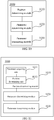
- FIG. 8 is a block diagram of a coil position adjustment apparatus 800 according to some embodiments of the present disclosure.
- the apparatus has the functions of realizing the above method examples.
- the functions may be implemented by hardware, or may be implemented by software which is performed by the hardware.
- the apparatus may be the power transmitting device as described above or may be arranged on the power transmitting device.
- the apparatus 800 may include an information acquiring module 810 and a position adjusting module 820.
- the information acquiring module 810 is configured to acquire position offset indication information between a transmitting coil in the power transmitting device and a receiving coil in a power receiving device.
- the power transmitting device is configured to wirelessly charge the power receiving device, and the position offset indication information is used to reflect a position offset between the transmitting coil and the receiving coil.
- the position adjusting module 820 is configured to adjust a position of the transmitting coil according to the position offset indication information.
- the coil position is adjusted by the power transmitting device according to the position offset between the transmitting coil and the receiving coil. If the power receiving device is not properly placed on the power transmitting device, the position of the transmitting coil is automatically adjusted, such that a geometric center of the transmitting coil coincides with or approaches that of the receiving coil as far as possible. In this way, the charging efficiency of the power receiving device is improved.
- the position offset indication information includes charging efficiency indication information
- the charging efficiency indication information is used to indicate a charging efficiency of the wireless charging.
- the position adjusting module 820 includes a condition detecting component 821, a position adjusting component 822, and an information acquiring component 823.
- the condition detecting component 821 is configured to detect whether the charging efficiency indication information satisfies a first predetermined condition.
- the position adjusting component 822 is configured to adjust the position of the transmitting coil if the charging efficiency indication information satisfies the first predetermined condition.
- the information acquiring component 823 is configured to re-acquire the charging efficiency indication information after the adjustment of the position of the transmitting coil, and detect whether the charging efficiency indication information satisfies the first predetermined condition by the condition detecting component until the charging efficiency indication information does not satisfy the first predetermined condition, and the position adjustment of the transmitting coil is stopped.
- the information acquiring module 810 is configured to:
- the position offset indication information further includes charging temperature indication information, and the charging temperature indication information is used to indicate a temperature of the power transmitting device.
- the condition detecting component 821 is further configured to detect whether the charging temperature indication information satisfies a second predetermined condition.
- the position adjusting component 822 is further configured to adjust the position of the transmitting coil if the charging temperature indication information satisfies the second predetermined condition.
- the information acquiring component is further configured to re-acquire the charging temperature indication information after the adjustment of the position of the transmitting coil, and re-detect whether the charging temperature indication information satisfies the second predetermined condition by the condition detecting component until the charging efficiency indication information does not satisfy the first predetermined condition and the charging temperature indication information does not satisfy the second predetermined condition, and the position adjustment of the transmitting coil is stopped.
- the information acquiring module 810 is further configured to: receive a position adjustment parameter from the power receiving device, and the position adjustment parameter is used to indicate an adjustment direction and an adjustment distance of the transmitting coil.
- the position adjusting module 820 is further configured to:
- FIG. 10 is a block diagram of an apparatus for adjusting a coil position according to another exemplary embodiment of the present disclosure.
- the apparatus has the functions of realizing the above method examples.
- the functions may be implemented by hardware, or may be implemented by corresponding software which is performed by hardware.
- the apparatus may be the power receiving device as described above or may be arranged on the power receiving device.
- the apparatus 1000 may include a position determining module 1010, a parameter determining module 1020, and a parameter transmitting module 1030.
- the position determining module 1010 is configured to determine a position of a transmitting coil in a power transmitting device configured to wirelessly charge the power receiving device by a magnetic induction sensor.
- the parameter determining module 1020 is configured to determine a position adjustment parameter of the transmitting coil according to a position of a receiving coil in the power receiving device and a position of the transmitting coil, and the position adjustment parameter is used to indicate an adjustment direction and an adjustment distance of the transmitting coil.
- the parameter transmitting module 1030 is configured to transmit the position adjustment parameter to the power transmitting device.
- the position adjustment parameter of the transmitting coil is determined by the power receiving device according to the position of the receiving coil and the position of the transmitting coil, and the position adjustment parameter is transmitted to the power transmitting device, such that the power transmitting device adjusts the position of the transmitting coil according to the position adjustment parameter. In this way, adjustment of the position of the transmitting coil is quick and consumes less time.
- the position determining module 1010 includes a parameter acquiring component 1011 and a position determining component 1012.
- the parameter acquiring component 1011 is configured to acquire a magnetic field parameter of a magnet in the power transmitting device by the magnetic induction sensor, and a central position of the magnet is aligned with a central position of the transmitting coil.
- the position determining component 1012 is configured to determine the position of the transmitting coil according to the magnetic field parameter of the magnet.
- the position determining module 1012 is configured to:
- the position determining module 1010 includes:
- the parameter determining module 1011 is configured to:
- the position determining module 1012 is configured to:
- the apparatus is described by only using division of the above functional modules as examples. In practice, the functions may be assigned to different functional modules for implementation as required. To be specific, the internal structure of the apparatus is divided into different functional modules to implement all or part of the above-described functions.
- Some embodiments of the present disclosure further provide a device for use in coil position adjustment, which may implement the method according to the present disclosure.
- the apparatus has the functions of practicing the above method examples. The functions may be implemented by hardware, or may be implemented by corresponding software which is performed by hardware.
- the apparatus may be the power transmitting device as described above or may be arranged on the power transmitting device.
- the device includes a processor and a memory for storing executable instructions. The processor is configured to:
- the position offset indication information includes charging efficiency indication information, and the charging efficiency indication information is used to indicate a charging efficiency of the wireless charging;
- the processor is configured to:
- the processor is configured to:
- the position offset indication information further includes charging temperature indication information, and the charging temperature indication information is used to indicate a temperature of the power transmitting device;
- the processor is further configured to: receive a position adjustment parameter from the power receiving device, the position adjustment parameter being used to indicate an adjustment direction and an adjustment distance of the transmitting coil.
- the processor is further configured to:
- Some embodiments of the present disclosure further provide a device for adjusting the coil position, which may implement the method according to the present disclosure.
- the apparatus has the functions of realizing the above method examples. The functions may be implemented by hardware, or may be implemented by corresponding software which is performed by hardware.
- the apparatus may be the power receiving device as described above or may be arranged on the power receiving device.
- the device includes a processor and a memory for storing executable instructions. The processor is configured to:
- the processor is configured to:
- the processor is further configured to:
- the processor is further configured to:
- the processor is further configured to:
- the processor is further configured to:
- FIG. 12 is a schematic structural diagram of a power transmitting device 1200 according to some embodiments of the present disclosure.
- the power transmitting device 1200 may include a power transmission assembly 1201, a transmitter/receiver 1202, and a processor 1203.
- the power transmission assembly 1201 is configured to wirelessly charge a power receiving device.
- the power transmission assembly 1201 may wirelessly charge the power receiving device by electromagnetic induction.
- no limitation is set to the constitution and structure of the power transmission assembly 1201.
- the transmitter/receiver 1202 is configured to support communication between the power transmitting device 1200 and other devices (for example, the power receiving device and/or other power transmitting devices).
- the processor 1203 controls and manages the action of the power transmitting device 1200, and is configured to perform the operations of the power transmitting device 1200.
- the processor 1203 may be further configured to perform the steps in the above method embodiments, and/or other steps in the technical solutions described in the embodiments of the present disclosure.
- the power transmitting device 1200 may include a memory 1204, wherein the memory 1204 is configured to store program code and data of the power transmitting device 1200.
- FIG. 12 only illustrates a simplified design of the power transmitting device 1200.
- the power transmitting device 1200 may include more or fewer components, and all the power transmitting devices that may realize the embodiments of the present disclosure shall fall within the protection scope of the embodiments of the present disclosure.
- FIG. 13 is a schematic structural diagram of a power receiving device 1300 according to some embodiments of the present disclosure.
- the power receiving device 1300 may include a power receiving assembly 1301, a transmitter/receiver 1302, and a processor 1303.
- the power receiving assembly 1301 is configured to receive a wireless charging power supplied by the power transmitting device.
- the power receiving assembly 1301 may receive, by electromagnetic induction, the wireless charging power supplied by the power transmitting device.
- no limitation is set to the constitution and structure of the power receiving assembly 1301.
- the transmitter/receiver 1302 is configured to support communication between the power receiving device 1300 and other devices (for example, the power transmitting device and/or other power receiving devices).
- the processor 1303 controls and manages the action of the power receiving device 1300, and is configured to perform the operations of the power receiving device 1300.
- the processor 1303 may be further configured to perform the steps in the above method embodiments, and/or other steps in the technical solutions described in the embodiments of the present disclosure.
- the power receiving device 1300 may include a memory 1304, wherein the memory 1304 is configured to store program code and data of the power receiving device 1300.
- FIG. 13 only illustrates a simplified design of the power receiving device 1300.
- the power receiving device 1300 may include more or fewer components, and all the power receiving devices that may practice the embodiments of the present disclosure shall fall within the protection scope of the embodiments of the present disclosure.
- An embodiment of the present disclosure further provides a non-transitory computer-readable storage medium which stores a computer program.
- the computer program is performed by a processor of a power transmitting device, the above-mentioned method for adjusting a coil position on the power transmitting device side is realized.
- An embodiment of the present disclosure further provides a non-transitory computer-readable storage medium which stores a computer program.
- the computer program is performed by a processor of a power transmitting device, the above-mentioned method for adjusting a coil position on the power receiving device side is realized.
- the non-transitory computer-readable storage medium may be a ROM (Read-Only Memory), a RAM (Random Access Memory), a CD-ROM, a magnetic tape, a floppy disc, an optical data storage device, and the like.
- the processor can execute the instructions stored on the medium to determine, by a magnetic induction sensor, a position of a transmitting coil in a power transmitting device configured to wirelessly charge the power receiving device; determine a position adjustment parameter of the transmitting coil according to a position of a receiving coil in the power receiving device and the position of the transmitting coil, wherein the position adjustment parameter is used to indicate an adjustment direction and an adjustment distance of the transmitting coil; and transmit the position adjustment parameter to the power transmitting device.
- the position offset indication information includes charging efficiency indication information, the charging efficiency indication information being used to indicate a charging efficiency of the wireless charging; and adjusting the position of the transmitting coil according to the position offset indication information includes: detecting whether the charging efficiency indication information satisfies a first predetermined condition; adjusting the position of the transmitting coil if the charging efficiency indication information satisfies the first predetermined condition; and after the adjustment of the position of the transmitting coil, re-acquiring the charging efficiency indication information, re-performing the step of detecting whether the charging efficiency indication information satisfies the first predetermined condition until the charging efficiency indication information does not satisfy the first predetermined condition, and stopping adjusting the position of the transmitting coil.
- the acquiring the position offset indication information between the transmitting coil in the power transmitting device and the receiving coil in the power receiving device includes:
- the position offset indication information further includes charging temperature indication information
- the charging temperature indication information is used to indicate a temperature of the power transmitting device
- the method further includes: detecting whether the charging temperature indication information satisfies a second predetermined condition; adjusting the position of the transmitting coil if the charging temperature indication information satisfies the second predetermined condition; and after the adjustment of the position of the transmitting coil, re-acquiring the charging temperature indication information, re-performing the steps from detecting whether the charging temperature indication information satisfies the second predetermined condition until the charging efficiency indication information does not satisfy the first predetermined condition and the charging temperature indication information does not satisfy the second predetermined condition, and stopping adjusting the position of the transmitting coil.
- the acquiring the position offset indication information between the transmitting coil in the power transmitting device and the receiving coil in the power receiving device includes: receiving a position adjustment parameter transmitted from the power receiving device, the position adjustment parameter being used to indicate an adjustment direction and an adjustment distance of the transmitting coil.
- the adjusting the position of the transmitting coil according to the position offset indication information includes:
- the determining, by the magnetic induction sensor, the position of the transmitting coil in the power transmitting device configured to charge the power receiving device includes:
- the determining the position of the transmitting coil according to the magnetic field parameter of the magnet includes:
- the determining, by the magnetic induction sensor, the position of the transmitting coil in the power transmitting device configured to charge the power receiving device includes:
- the acquiring the magnetic field parameter of the transmitting coil by the magnetic induction sensor includes:
- the determining the position of the transmitting coil according to the magnetic field parameter of the transmitting coil includes:
- an apparatus for adjusting a coil position which can applied to a power transmitting device.
- the apparatus includes:
- the position offset indication information includes charging efficiency indication information, and the charging efficiency indication information is used to indicate a charging efficiency of the wireless charging;
- the information acquiring portion is further configured to:
- the position offset indication information further includes charging temperature indication information, and the charging temperature indication information being used to indicate a temperature of the power transmitting device; and the condition detecting component is further configured to detect whether the charging temperature indication information satisfies a second predetermined condition; the position adjusting component is further configured to adjust the position of the transmitting coil if the charging temperature indication information satisfies the second predetermined condition; and
- the information acquiring component is further configured to, after the adjustment of the position of the transmitting coil, re-acquire the charging temperature indication information, re-detect whether the charging temperature indication information satisfies the second predetermined condition by the condition detecting component again until the charging efficiency indication information does not satisfy the first predetermined condition and the charging temperature indication information does not satisfy the second predetermined condition, and stop adjusting the position of the transmitting coil.
- the information acquiring portion is further configured to: receive a position adjustment parameter transmitted from the power receiving device, the position adjustment parameter being used to indicate an adjustment direction and an adjustment distance of the transmitting coil.
- the position adjusting portion is further configured to:
- an apparatus for adjusting a coil position which is applied to a power receiving device.
- the apparatus includes:
- the position determining portion includes:
- the position determining component is further configured to:
- the position determining portion includes:
- the parameter determining component is further configured to:
- the position determining component is further configured to:
- the coil position can be adjusted by the power transmitting device according to the position offset between the transmitting coil and the receiving coil. If the power receiving device is not properly placed on the power transmitting device, the position of the transmitting coil is automatically adjusted, such that a geometric center of the transmitting coil coincides with or approaches that of the receiving coil as far as possible. In this way, the charging efficiency of the power receiving device is improved.
- the element defined by the sentence "includes a" does not exclude the existence of another identical element in the process, the method, or the device including the element.
- the terms “some embodiments,” or “example,” and the like may indicate a specific feature described in connection with the embodiment or example, a structure, a material or feature included in at least one embodiment or example.
- the schematic representation of the above terms is not necessarily directed to the same embodiment or example.
- circuit(s), unit(s), device(s), component(s), etc. in some occurrences singular forms are used, and in some other occurrences plural forms are used in the descriptions of various embodiments. It should be noted; however, the single or plural forms are not limiting but rather are for illustrative purposes. Unless it is expressly stated that a single unit, device, or component etc. is employed, or it is expressly stated that a plurality of units, devices or components, etc. are employed, the circuit(s), unit(s), device(s), component(s), etc. can be singular, or plural.
- the disclosed apparatuses, devices, and methods can be implemented in other manners.
- the abovementioned devices can employ various methods of use or implementation as disclosed herein.
- the terms “installed,” “connected,” “coupled,” “fixed” and the like shall be understood broadly, and may be either a fixed connection or a detachable connection, or integrated, unless otherwise explicitly defined. These terms can refer to mechanical or electrical connections, or both. Such connections can be direct connections or indirect connections through an intermediate medium. These terms can also refer to the internal connections or the interactions between elements. The specific meanings of the above terms in the present disclosure can be understood by those of ordinary skill in the art on a case-by-case basis.
- Dividing the device into different "regions,” “units,” “components” or “layers,” etc. merely reflect various logical functions according to some embodiments, and actual implementations can have other divisions of "regions,” “units,” “components” or “layers,” etc. realizing similar functions as described above, or without divisions. For example, multiple regions, units, or layers, etc. can be combined or can be integrated into another system. In addition, some features can be omitted, and some steps in the methods can be skipped.
- the units, components, regions, or layers, etc. in the devices provided by various embodiments described above can be provided in the one or more devices described above. They can also be located in one or multiple devices that is (are) different from the example embodiments described above or illustrated in the accompanying drawings.
- the units, regions, or layers, etc. in various embodiments described above can be integrated into one module or divided into several sub-modules.
- modules may have modular configurations, or are composed of discrete components, but nonetheless can be referred to as “modules” in general.
- the "components,” “modules,” “blocks,” “portions,” or “units” referred to herein may or may not be in modular forms.
- first and second are used for descriptive purposes only and are not to be construed as indicating or implying a relative importance or implicitly indicating the number of technical features indicated.
- elements referred to as “first” and “second” may include one or more of the features either explicitly or implicitly.
- a plurality indicates two or more unless specifically defined otherwise.
Landscapes
- Engineering & Computer Science (AREA)
- Power Engineering (AREA)
- Computer Networks & Wireless Communication (AREA)
- Physics & Mathematics (AREA)
- Electromagnetism (AREA)
- Charge And Discharge Circuits For Batteries Or The Like (AREA)
- Current-Collector Devices For Electrically Propelled Vehicles (AREA)
Applications Claiming Priority (1)
| Application Number | Priority Date | Filing Date | Title |
|---|---|---|---|
| CN201910577689.7A CN112152325B (zh) | 2019-06-28 | 2019-06-28 | 线圈位置调整方法、装置和存储介质 |
Publications (2)
| Publication Number | Publication Date |
|---|---|
| EP3758191A2 true EP3758191A2 (fr) | 2020-12-30 |
| EP3758191A3 EP3758191A3 (fr) | 2021-03-24 |
Family
ID=70476020
Family Applications (1)
| Application Number | Title | Priority Date | Filing Date |
|---|---|---|---|
| EP20171824.4A Pending EP3758191A3 (fr) | 2019-06-28 | 2020-04-28 | Procédé et appareil de réglage de position de bobine d`un emetteur dans une transmission d`energie sans fil |
Country Status (3)
| Country | Link |
|---|---|
| US (1) | US11462954B2 (fr) |
| EP (1) | EP3758191A3 (fr) |
| CN (1) | CN112152325B (fr) |
Cited By (2)
| Publication number | Priority date | Publication date | Assignee | Title |
|---|---|---|---|---|
| CN114530950A (zh) * | 2022-04-08 | 2022-05-24 | 北京理工大学 | 单线圈空间定位方法、装置、终端设备和存储介质 |
| EP4089881A4 (fr) * | 2021-04-02 | 2023-09-13 | Honor Device Co., Ltd. | Procédé d'alignement de bobine et système de charge |
Families Citing this family (8)
| Publication number | Priority date | Publication date | Assignee | Title |
|---|---|---|---|---|
| US11387690B1 (en) * | 2021-03-11 | 2022-07-12 | Hong Kong Applied Science and Technology Research Institute Company, Limited | Self-aligning wireless power transfer system that switches power current into aligning electromagnets |
| CN112907121B (zh) * | 2021-03-22 | 2023-02-03 | 拉扎斯网络科技(上海)有限公司 | 充电调度方法、装置、计算机设备及计算机可读存储介质 |
| DE102022209945A1 (de) * | 2021-09-24 | 2023-03-30 | Apple Inc. | Systeme und verfahren zur erkennung der kopplung von drahtlosen ladevorrichtungen |
| CN114336987B (zh) * | 2021-12-16 | 2025-02-25 | 珠海格力电器股份有限公司 | 自动调节无线充电匹配度的方法、装置和无线充电设备 |
| CN115208084A (zh) * | 2022-07-07 | 2022-10-18 | 楚山(深圳)新能源科技有限公司 | 线圈模块自动对准方法、控制器及无线充电桩 |
| CN115333260A (zh) * | 2022-10-17 | 2022-11-11 | 北京紫光芯能科技有限公司 | 用于调整磁链的方法及装置、无线充电接收设备 |
| CN119218014A (zh) * | 2023-06-28 | 2024-12-31 | 华为技术有限公司 | 供电装置及其控制方法、控制装置和系统 |
| CN117856466B (zh) * | 2024-01-16 | 2024-10-01 | 深圳市中亚华宇电子有限公司 | 一种无线充电的电磁感应控制方法及系统 |
Family Cites Families (19)
| Publication number | Priority date | Publication date | Assignee | Title |
|---|---|---|---|---|
| JP3771878B2 (ja) * | 2002-06-26 | 2006-04-26 | 京セラ株式会社 | 積層誘電体アンテナ |
| JP4600453B2 (ja) | 2007-09-26 | 2010-12-15 | セイコーエプソン株式会社 | 送電制御装置、送電装置、受電装置、無接点電力伝送システム、電子機器、2次コイル位置検出方法および1次コイルの位置決め方法 |
| JP2010183706A (ja) | 2009-02-04 | 2010-08-19 | Sanyo Electric Co Ltd | 充電台 |
| JP5348183B2 (ja) * | 2010-08-18 | 2013-11-20 | 三洋電機株式会社 | 電池内蔵機器と充電装置 |
| KR101243587B1 (ko) * | 2011-02-17 | 2013-03-20 | 주식회사 팬택 | 무접점 충전 장치, 무접점 충전 시스템 및 무접점 충전 방법 |
| US9379571B2 (en) * | 2011-07-11 | 2016-06-28 | Delphi Technologies, Inc. | Electrical charging system having energy coupling arrangement for wireless energy transmission therebetween |
| CN102545326A (zh) * | 2011-12-30 | 2012-07-04 | 中兴通讯股份有限公司 | 无线充电装置及系统、移动终端 |
| CN202918004U (zh) | 2012-10-15 | 2013-05-01 | 东莞富强电子有限公司 | 无线充电器 |
| EP2793359A4 (fr) * | 2013-03-06 | 2015-12-02 | Hanshinkijeon Co Ltd | Chargeur sans fil apte à un réglage de position automatique et procédé de charge l'utilisant |
| KR102342855B1 (ko) | 2015-03-05 | 2021-12-22 | 지이 하이브리드 테크놀로지스, 엘엘씨 | 무선 전력 전송 시스템에서 코일 위치 조절 방법 및 그 장치 |
| CN106300578B (zh) * | 2015-06-26 | 2021-08-10 | 苏州宝时得电动工具有限公司 | 自主移动设备及其无线充电系统 |
| CN105691222B (zh) * | 2015-12-21 | 2017-10-03 | 中惠创智无线供电技术有限公司 | 一种接收电磁铁组件位置可调的电动汽车无线充电装置 |
| CN105539186B (zh) * | 2016-01-20 | 2017-07-07 | 厦门新页科技有限公司 | 一种汽车无线充电对准匹配系统及方法 |
| CN106568376A (zh) * | 2016-04-20 | 2017-04-19 | 中兴新能源汽车有限责任公司 | 充电线圈位置检测装置、线圈偏移检测方法、装置及基建端和车载端 |
| CN105958658A (zh) | 2016-05-20 | 2016-09-21 | 联想(北京)有限公司 | 一种充电位置提示方法及电子设备 |
| CN108123556A (zh) | 2017-12-06 | 2018-06-05 | 深圳市华宝新能源股份有限公司 | 功率接收装置、无线充电提示系统、方法及设备和介质 |
| WO2020130162A1 (fr) * | 2017-12-15 | 2020-06-25 | 경문건 | Système de charge sans fil autonome et procédé basé sur un suivi de perte de puissance |
| CN108988499A (zh) | 2018-06-20 | 2018-12-11 | 欧格仕(厦门)科技有限公司 | 充电设备 |
| CN108923547A (zh) * | 2018-08-24 | 2018-11-30 | 深圳市沃特沃德股份有限公司 | 自动调整位置的无线充电的方法和装置 |
-
2019
- 2019-06-28 CN CN201910577689.7A patent/CN112152325B/zh active Active
-
2020
- 2020-04-07 US US16/841,698 patent/US11462954B2/en active Active
- 2020-04-28 EP EP20171824.4A patent/EP3758191A3/fr active Pending
Cited By (2)
| Publication number | Priority date | Publication date | Assignee | Title |
|---|---|---|---|---|
| EP4089881A4 (fr) * | 2021-04-02 | 2023-09-13 | Honor Device Co., Ltd. | Procédé d'alignement de bobine et système de charge |
| CN114530950A (zh) * | 2022-04-08 | 2022-05-24 | 北京理工大学 | 单线圈空间定位方法、装置、终端设备和存储介质 |
Also Published As
| Publication number | Publication date |
|---|---|
| EP3758191A3 (fr) | 2021-03-24 |
| CN112152325A (zh) | 2020-12-29 |
| US20200412181A1 (en) | 2020-12-31 |
| CN112152325B (zh) | 2023-06-20 |
| US11462954B2 (en) | 2022-10-04 |
Similar Documents
| Publication | Publication Date | Title |
|---|---|---|
| US11462954B2 (en) | Method and apparatus for adjusting coil position | |
| EP2630718B1 (fr) | Procédé et appareil de chargement sans fil | |
| KR102544891B1 (ko) | 무선 전력 전송 시스템에서 코일 위치 조절 방법 및 그 장치 | |
| US11757309B2 (en) | Apparatus and method for detecting foreign objects in wireless power transmission system | |
| US9948149B2 (en) | Method and apparatus for wireless power transfer | |
| US9859719B2 (en) | Method and apparatus for wireless power transfer | |
| EP2430724B1 (fr) | Dispositif d'alimentation électrique, son procédé de commande et système d'alimentation électrique | |
| US10848011B2 (en) | Apparatus and method for detecting foreign object in wireless power transmitting system | |
| EP2608352A1 (fr) | Émetteur de puissance sans fil, récepteur d'alimentation sans fil et procédé de transmission d'alimentation sans fil | |
| US20120212178A1 (en) | Device, system, and method for inductive charging | |
| US20120038317A1 (en) | Wireless charging system | |
| US9570931B2 (en) | Electronic device and electronic device charging system | |
| WO2011118371A1 (fr) | Dispositif d'alimentation sans contact et système de charge sans contact | |
| EP4106147A1 (fr) | Dispositif de transmission d'énergie et dispositif de réception d'énergie, et procédé de commande et programme associé | |
| CN104253490A (zh) | 馈电装置和馈电系统 | |
| KR20230113930A (ko) | 무선 전력 전송 장치 및 방법 | |
| JP2016111791A (ja) | 送電装置、送電装置の制御方法、プログラム | |
| CN106849215A (zh) | 一种非接触式充电系统和方法 | |
| KR101034740B1 (ko) | 무선 전력전송 시스템 및 방법 | |
| EP3407461A1 (fr) | Système et procédé de charge sans fil d'un dispositif de balise et / ou de capteur | |
| KR101228105B1 (ko) | 무접점 충전 시스템 및 그 제어방법 | |
| CN109193974A (zh) | 一种优化无线充电稳定性的方法 | |
| EP3242374A1 (fr) | Dispositif de transmission de puissance sans fil et système de charge sans fil le comprenant | |
| KR20160051931A (ko) | 자기 공진 방식을 이용한 무선 충전 시스템 | |
| JP2017135789A (ja) | 磁気共鳴式給電システム |
Legal Events
| Date | Code | Title | Description |
|---|---|---|---|
| PUAI | Public reference made under article 153(3) epc to a published international application that has entered the european phase |
Free format text: ORIGINAL CODE: 0009012 |
|
| STAA | Information on the status of an ep patent application or granted ep patent |
Free format text: STATUS: THE APPLICATION HAS BEEN PUBLISHED |
|
| AK | Designated contracting states |
Kind code of ref document: A2 Designated state(s): AL AT BE BG CH CY CZ DE DK EE ES FI FR GB GR HR HU IE IS IT LI LT LU LV MC MK MT NL NO PL PT RO RS SE SI SK SM TR |
|
| AX | Request for extension of the european patent |
Extension state: BA ME |
|
| PUAL | Search report despatched |
Free format text: ORIGINAL CODE: 0009013 |
|
| AK | Designated contracting states |
Kind code of ref document: A3 Designated state(s): AL AT BE BG CH CY CZ DE DK EE ES FI FR GB GR HR HU IE IS IT LI LT LU LV MC MK MT NL NO PL PT RO RS SE SI SK SM TR |
|
| AX | Request for extension of the european patent |
Extension state: BA ME |
|
| RIC1 | Information provided on ipc code assigned before grant |
Ipc: H02J 50/90 20160101ALI20210217BHEP Ipc: H02J 50/10 20160101AFI20210217BHEP |
|
| STAA | Information on the status of an ep patent application or granted ep patent |
Free format text: STATUS: REQUEST FOR EXAMINATION WAS MADE |
|
| 17P | Request for examination filed |
Effective date: 20210923 |
|
| RBV | Designated contracting states (corrected) |
Designated state(s): AL AT BE BG CH CY CZ DE DK EE ES FI FR GB GR HR HU IE IS IT LI LT LU LV MC MK MT NL NO PL PT RO RS SE SI SK SM TR |
|
| STAA | Information on the status of an ep patent application or granted ep patent |
Free format text: STATUS: EXAMINATION IS IN PROGRESS |
|
| 17Q | First examination report despatched |
Effective date: 20220512 |
|
| REG | Reference to a national code |
Ref country code: DE Ref legal event code: R079 Free format text: PREVIOUS MAIN CLASS: H02J0050100000 Ipc: H02J0007020000 |