WO2020130162A1 - Système de charge sans fil autonome et procédé basé sur un suivi de perte de puissance - Google Patents
Système de charge sans fil autonome et procédé basé sur un suivi de perte de puissance Download PDFInfo
- Publication number
- WO2020130162A1 WO2020130162A1 PCT/KR2018/015997 KR2018015997W WO2020130162A1 WO 2020130162 A1 WO2020130162 A1 WO 2020130162A1 KR 2018015997 W KR2018015997 W KR 2018015997W WO 2020130162 A1 WO2020130162 A1 WO 2020130162A1
- Authority
- WO
- WIPO (PCT)
- Prior art keywords
- wireless charging
- power
- power loss
- charging system
- wireless device
- Prior art date
- Legal status (The legal status is an assumption and is not a legal conclusion. Google has not performed a legal analysis and makes no representation as to the accuracy of the status listed.)
- Ceased
Links
Images




Classifications
-
- H—ELECTRICITY
- H02—GENERATION; CONVERSION OR DISTRIBUTION OF ELECTRIC POWER
- H02J—ELECTRIC POWER NETWORKS; CIRCUIT ARRANGEMENTS OR SYSTEMS FOR SUPPLYING OR DISTRIBUTING ELECTRIC POWER; SYSTEMS FOR STORING ELECTRIC ENERGY
- H02J50/00—Circuit arrangements or systems for wireless supply or distribution of electric power
- H02J50/80—Circuit arrangements or systems for wireless supply or distribution of electric power involving the exchange of data, concerning supply or distribution of electric power, between transmitting devices and receiving devices
-
- H—ELECTRICITY
- H02—GENERATION; CONVERSION OR DISTRIBUTION OF ELECTRIC POWER
- H02J—ELECTRIC POWER NETWORKS; CIRCUIT ARRANGEMENTS OR SYSTEMS FOR SUPPLYING OR DISTRIBUTING ELECTRIC POWER; SYSTEMS FOR STORING ELECTRIC ENERGY
- H02J50/00—Circuit arrangements or systems for wireless supply or distribution of electric power
- H02J50/90—Circuit arrangements or systems for wireless supply or distribution of electric power involving detection or optimisation of position, e.g. alignment
-
- B—PERFORMING OPERATIONS; TRANSPORTING
- B60—VEHICLES IN GENERAL
- B60L—PROPULSION OF ELECTRICALLY-PROPELLED VEHICLES; SUPPLYING ELECTRIC POWER FOR AUXILIARY EQUIPMENT OF ELECTRICALLY-PROPELLED VEHICLES; ELECTRODYNAMIC BRAKE SYSTEMS FOR VEHICLES IN GENERAL; MAGNETIC SUSPENSION OR LEVITATION FOR VEHICLES; MONITORING OPERATING VARIABLES OF ELECTRICALLY-PROPELLED VEHICLES; ELECTRIC SAFETY DEVICES FOR ELECTRICALLY-PROPELLED VEHICLES
- B60L53/00—Methods of charging batteries, specially adapted for electric vehicles; Charging stations or on-board charging equipment therefor; Exchange of energy storage elements in electric vehicles
- B60L53/10—Methods of charging batteries, specially adapted for electric vehicles; Charging stations or on-board charging equipment therefor; Exchange of energy storage elements in electric vehicles characterised by the energy transfer between the charging station and the vehicle
- B60L53/12—Inductive energy transfer
- B60L53/124—Detection or removal of foreign bodies
-
- B—PERFORMING OPERATIONS; TRANSPORTING
- B60—VEHICLES IN GENERAL
- B60L—PROPULSION OF ELECTRICALLY-PROPELLED VEHICLES; SUPPLYING ELECTRIC POWER FOR AUXILIARY EQUIPMENT OF ELECTRICALLY-PROPELLED VEHICLES; ELECTRODYNAMIC BRAKE SYSTEMS FOR VEHICLES IN GENERAL; MAGNETIC SUSPENSION OR LEVITATION FOR VEHICLES; MONITORING OPERATING VARIABLES OF ELECTRICALLY-PROPELLED VEHICLES; ELECTRIC SAFETY DEVICES FOR ELECTRICALLY-PROPELLED VEHICLES
- B60L53/00—Methods of charging batteries, specially adapted for electric vehicles; Charging stations or on-board charging equipment therefor; Exchange of energy storage elements in electric vehicles
- B60L53/30—Constructional details of charging stations
- B60L53/35—Means for automatic or assisted adjustment of the relative position of charging devices and vehicles
- B60L53/38—Means for automatic or assisted adjustment of the relative position of charging devices and vehicles specially adapted for charging by inductive energy transfer
-
- H—ELECTRICITY
- H02—GENERATION; CONVERSION OR DISTRIBUTION OF ELECTRIC POWER
- H02J—ELECTRIC POWER NETWORKS; CIRCUIT ARRANGEMENTS OR SYSTEMS FOR SUPPLYING OR DISTRIBUTING ELECTRIC POWER; SYSTEMS FOR STORING ELECTRIC ENERGY
- H02J50/00—Circuit arrangements or systems for wireless supply or distribution of electric power
- H02J50/10—Circuit arrangements or systems for wireless supply or distribution of electric power using inductive coupling
-
- H—ELECTRICITY
- H02—GENERATION; CONVERSION OR DISTRIBUTION OF ELECTRIC POWER
- H02J—ELECTRIC POWER NETWORKS; CIRCUIT ARRANGEMENTS OR SYSTEMS FOR SUPPLYING OR DISTRIBUTING ELECTRIC POWER; SYSTEMS FOR STORING ELECTRIC ENERGY
- H02J50/00—Circuit arrangements or systems for wireless supply or distribution of electric power
- H02J50/60—Circuit arrangements or systems for wireless supply or distribution of electric power responsive to the presence of foreign objects, e.g. detection of living beings
-
- H—ELECTRICITY
- H02—GENERATION; CONVERSION OR DISTRIBUTION OF ELECTRIC POWER
- H02J—ELECTRIC POWER NETWORKS; CIRCUIT ARRANGEMENTS OR SYSTEMS FOR SUPPLYING OR DISTRIBUTING ELECTRIC POWER; SYSTEMS FOR STORING ELECTRIC ENERGY
- H02J7/00—Circuit arrangements for charging or discharging batteries or for supplying loads from batteries
- H02J7/90—Regulation of charging or discharging current or voltage
- H02J7/96—Regulation of charging or discharging current or voltage in response to battery voltage
-
- H—ELECTRICITY
- H02—GENERATION; CONVERSION OR DISTRIBUTION OF ELECTRIC POWER
- H02J—ELECTRIC POWER NETWORKS; CIRCUIT ARRANGEMENTS OR SYSTEMS FOR SUPPLYING OR DISTRIBUTING ELECTRIC POWER; SYSTEMS FOR STORING ELECTRIC ENERGY
- H02J2105/00—Networks for supplying or distributing electric power characterised by their spatial reach or by the load
- H02J2105/40—Networks for supplying or distributing electric power characterised by their spatial reach or by the load characterised by the loads connecting to the networks or being supplied by the networks
- H02J2105/44—Portable electronic devices
-
- Y—GENERAL TAGGING OF NEW TECHNOLOGICAL DEVELOPMENTS; GENERAL TAGGING OF CROSS-SECTIONAL TECHNOLOGIES SPANNING OVER SEVERAL SECTIONS OF THE IPC; TECHNICAL SUBJECTS COVERED BY FORMER USPC CROSS-REFERENCE ART COLLECTIONS [XRACs] AND DIGESTS
- Y02—TECHNOLOGIES OR APPLICATIONS FOR MITIGATION OR ADAPTATION AGAINST CLIMATE CHANGE
- Y02T—CLIMATE CHANGE MITIGATION TECHNOLOGIES RELATED TO TRANSPORTATION
- Y02T10/00—Road transport of goods or passengers
- Y02T10/60—Other road transportation technologies with climate change mitigation effect
- Y02T10/70—Energy storage systems for electromobility, e.g. batteries
-
- Y—GENERAL TAGGING OF NEW TECHNOLOGICAL DEVELOPMENTS; GENERAL TAGGING OF CROSS-SECTIONAL TECHNOLOGIES SPANNING OVER SEVERAL SECTIONS OF THE IPC; TECHNICAL SUBJECTS COVERED BY FORMER USPC CROSS-REFERENCE ART COLLECTIONS [XRACs] AND DIGESTS
- Y02—TECHNOLOGIES OR APPLICATIONS FOR MITIGATION OR ADAPTATION AGAINST CLIMATE CHANGE
- Y02T—CLIMATE CHANGE MITIGATION TECHNOLOGIES RELATED TO TRANSPORTATION
- Y02T10/00—Road transport of goods or passengers
- Y02T10/60—Other road transportation technologies with climate change mitigation effect
- Y02T10/7072—Electromobility specific charging systems or methods for batteries, ultracapacitors, supercapacitors or double-layer capacitors
-
- Y—GENERAL TAGGING OF NEW TECHNOLOGICAL DEVELOPMENTS; GENERAL TAGGING OF CROSS-SECTIONAL TECHNOLOGIES SPANNING OVER SEVERAL SECTIONS OF THE IPC; TECHNICAL SUBJECTS COVERED BY FORMER USPC CROSS-REFERENCE ART COLLECTIONS [XRACs] AND DIGESTS
- Y02—TECHNOLOGIES OR APPLICATIONS FOR MITIGATION OR ADAPTATION AGAINST CLIMATE CHANGE
- Y02T—CLIMATE CHANGE MITIGATION TECHNOLOGIES RELATED TO TRANSPORTATION
- Y02T90/00—Enabling technologies or technologies with a potential or indirect contribution to GHG emissions mitigation
- Y02T90/10—Technologies relating to charging of electric vehicles
- Y02T90/12—Electric charging stations
-
- Y—GENERAL TAGGING OF NEW TECHNOLOGICAL DEVELOPMENTS; GENERAL TAGGING OF CROSS-SECTIONAL TECHNOLOGIES SPANNING OVER SEVERAL SECTIONS OF THE IPC; TECHNICAL SUBJECTS COVERED BY FORMER USPC CROSS-REFERENCE ART COLLECTIONS [XRACs] AND DIGESTS
- Y02—TECHNOLOGIES OR APPLICATIONS FOR MITIGATION OR ADAPTATION AGAINST CLIMATE CHANGE
- Y02T—CLIMATE CHANGE MITIGATION TECHNOLOGIES RELATED TO TRANSPORTATION
- Y02T90/00—Enabling technologies or technologies with a potential or indirect contribution to GHG emissions mitigation
- Y02T90/10—Technologies relating to charging of electric vehicles
- Y02T90/14—Plug-in electric vehicles
Definitions
- the wireless charging system has a method of inducing a user who wants to charge by manually adjusting the charging position, and a so-called free-positioning method of moving the charging system to move the central position of the transmitting coil to the central position of the receiving coil.
- various techniques can be applied to determine the presence and location of a charging object, but currently well-known methods include a position detection circuit board and a current sensing detector consisting of an X-axis loop coil arrangement and a Y-axis loop coil arrangement.
- There is a method of using a position detection device In this way, the charger detects whether the charging object has entered the chargeable area and the position of the charging object to move the power transmission coil to perform optimal charging.
- this method has a disadvantage in that a cost is high due to the implementation of the loop coil circuit board covering the entire area of the pad and a method of detecting a presence of a charging object with high reliability is required.
- the present invention relates to an autonomous wireless charging system, and more specifically, in terms of performance, a microcontroller unit (MCU: Microcontroller unit) located in a system control unit for a central location of a receiving coil of a wireless device equipped with a battery placed on a charger pad; Since it is weak afterwards, it is called'controller' and periodically tracks the difference in the power loss value generated during the Foreign Object Detection (FOD) process of the power transmitter, thereby precisely tracking the center position of the receiving coil of the wireless device. Even if there is a positional displacement of the wireless device, the transmission coil mounted on the mobile device is accurately moved again to the displaced position through threshold identification or, if necessary, by using a sensor matrix.
- MCU Microcontroller unit
- the present invention relates to an autonomous wireless charging device based on a tray-type case and power loss tracking, which have high efficiency of hardware and cost to provide the best wireless charging efficiency by optimally adapting to a wireless device located on a pad while moving only a certain stroke in the vertical direction.
- efficient energy transmission is achieved by coupling the near-field energy of the power transmission induction coil to the power reception induction coil in electromagnetic waves.
- the wireless charger for moving the coil is very expensive because the circuit for detecting the position of the wireless device located on the pad uses a detection circuit having a size almost similar to the pad area. There is an inefficient disadvantage.
- wireless chargers for free-positioning are proposed to freely mount a wireless device on a pad, it is evaluated that it does not completely fulfill its role or make it cost-effective.
- the center of the transmitting coil of the charger should be moved to the center of the receiving coil of the wireless device whenever necessary, and because of the burden of ensuring optimal charging efficiency regardless of where the wireless device is placed in the pad.
- a lot of material cost and component cost are excessively required, and accordingly, an undesirable problem occurs in size and durability of the operation power.
- Patent Document 0005 in many cases, a car indoor wireless charging unit system is installed and used inside a vehicle front console, but due to the characteristics of a moving car, the operating environment in which the position of a smartphone mounted in the vehicle can be easily displaced ( If it is exposed to a mound, curve, sudden stop, etc., away from the center of the charging pad, the charging efficiency drops rapidly and normal charging cannot be achieved, and even severe heat is generated. It takes the form of stopping automatically.
- Patent Document 1 Korean Patent Publication No. 2014-0067101 (2014.6.3.)
- Patent Document 2 Korean Patent Publication No. 2014-0085591 (2014.7.7)
- Patent Document 3 Korean Patent Publication No. 2015-0054887 (2015.5.20)
- Patent Document 4 Korean Patent Publication No. 2017-0008800 (2017.1.24)
- Patent Document 5 Korean Registered Patent No. 1701054 (2017.1.23)
- Patent Document 6 Korean Patent Publication No. 2012-0099571 (2012.7.11)
- Patent Document 7 Korean Registered Patent No. 0841135 (2008.6.18)
- Patent Document 8 Korean Registered Patent No. 1250290 (2013.3.28)
- Patent Document 9 Korean Patent Publication No. 2008-0081480 (2008.9.10)
- Patent Document 10 Korean Patent Publication No. 2012-0014878 (2012.2.20)
- Patent Document 11 Korean Patent Publication No. 2014-0019955 (2014.2.18)
- Patent Document 12 Chinese Patent Publication No. 102882243 (2013.01.16)
- Patent Document 13 US Registered Patent No. 8981719 (2015.03.17)
- Patent Document 14 U.S. Patent No. 9018900 (2015.4.28)
- Patent Document 15 U.S. Patent No. 9312711 (2016.4.12)
- Patent Document 16 U.S. Patent No. 9853484 (December 26, 2017)
- the present invention is to solve the problem of the hardware inefficiency, the structural problem in which there is a dead space where wireless charging is not possible, as a result, the cost inefficiency, etc. It detects the position through the structure of moving the transmission coil only in the stroke zone, but without using the position detection circuit of the receiving coil, it monitors the periodic power loss value calculated by the foreign material detection algorithm and transmits the coil in the position direction detected within a certain time. It is an object of the present invention to provide an autonomous wireless charging system that can greatly increase hardware and cost efficiency by allowing the mobile device to charge a wireless device.
- the present invention inserts an X-axis motor and a Y-axis motor into a through hole connecting between the slider and the Y-axis rail, and between the Y-axis rail and the X-axis rail, without disturbing movement along the X-axis rail and Y-axis rail.
- the aim is to provide an autonomous wireless charging system capable of producing as slim as possible.
- the present invention adopts a tray-shaped case, and the controller sets a basic value or a threshold value based on the power loss value generated in the process of detecting the foreign matter of the power transmitter, and through periodic power loss value monitoring
- the autonomous wireless charging system based on power loss tracking, which moves the transmission coil within a predetermined time in the sensed position direction to autonomously charge the wireless device or performs position tracking again when the position of the wireless device is displaced, the autonomy It is located in the central part of the wireless charging system and moves the transmission coil only in the stroke zone that can move in the vertical direction.
- the autonomous wireless charging system includes a controller that detects a location of a wireless device therein, but charges the wireless device by including a mobile device that moves the transmission coil in correspondence with the controller only within the stroke zone.
- the autonomous wireless charging system identifies the difference from the threshold value and restarts the transmitting coil, or, if necessary, optionally uses a sensor matrix to remove the position of the wireless device or remove the wireless device.
- the wireless device is charged by including a control unit for re-moving the transmission coil by calculating whether or not and the displaced direction of the displaced wireless device.
- the moving unit portion using an X-Y guide using a slide bearing method in which the driving portion is disposed between the guide rail and the slider.
- the present invention is a stationary charger, tray-type charger, office desk and sofa, furniture, treadmill, vehicle front console, wireless charging mouse for games, smartphone charging pads, garages and parking lots using ground-mounted or embedded pads for charging electric vehicles. It is applied to any one of the internal charging devices.
- the present invention made as described above increases the charging efficiency to the maximum by aligning the center of the transmitting coil and the receiving coil by tracking the position of the charging object using the power loss value used in the process of detecting the foreign matter in the power transmitter without using the position detecting circuit board.
- the effective charging efficiency of the autonomous wireless charging system based on power loss tracking may be defined as E max (maximum effective charging efficiency provided by the system at any position on the pad). That is, E max is the maximum charging efficiency that the charging system can provide.
- the tray-type case has a structure that reduces the stroke zone of the mobile device by about 4 times or more, thereby reducing the size and distance of the mobile device, and does not employ a position detection circuit board. Since it is not possible, sufficient space can be secured, and assembling performance is improved, and the stacking thickness of the wireless charging system can be reduced.
- the present invention has a structure in which a driving unit (driving motor, rack and pinion gear) is disposed between a guide rail (X, Y-axis rail) and a slider, and a blind spot is removed and stable driving when applied to a vehicle (smooth movement, Noise reduction).
- a driving unit driving motor, rack and pinion gear
- the present invention is not only a tray-type case shape that limits the mounting position of the wireless device, but also a stationary autonomous wireless charger, a tray-type autonomous wireless charger, office and conference room desks, sofas, furniture, treadmills, a vehicle console, and a wireless charging mouse for games. And it is applied to any one of the internal charging device of a garage and parking lot for charging an electric vehicle using a smartphone-compatible charging pad, a ground surface installation, or an underground buried pad.
- the present invention is a conference room or cafe that is powered on, furniture such as a table or office desk in a hotel, a sofa in a home, a car interior, and a place such as a garage or a parking lot.
- furniture such as a table or office desk in a hotel, a sofa in a home, a car interior, and a place such as a garage or a parking lot.
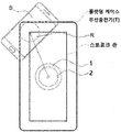
- FIG. 1 is a view showing an example of the alignment of the power transmission coil and the power receiving coil by moving the center of the power transmission coil to a corner toward the central position of the power receiving coil in a large stroke zone in the flat case wireless charger in the conventional invention.
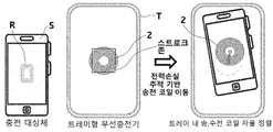
- FIG. 2 is a view showing an example of a power transmission coil and a power receiving coil alignment by moving the center of the power transmission coil to a center position of the power receiving coil only in a very small stroke zone in the tray type wireless charger according to the present invention.
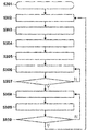
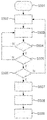
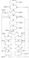
- FIG. 3 is a view showing an overall operation flowchart of an autonomous wireless charging system based on power loss tracking according to the present invention.
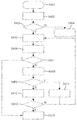
- FIG. 4 is a view showing a control flow diagram of a mobile device in an autonomous wireless charging system based on power loss tracking according to the present invention.
- FIG. 5 is a view showing an operation flowchart when the mobile device of the autonomous wireless charging system based on power loss tracking according to the present invention is stopped and being charged.
- FIG. 6 is a view showing a flow chart of the mobile device of the autonomous wireless charging system based on power loss tracking according to the present invention to calculate the movement direction.
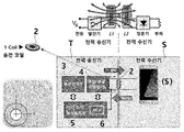
- FIG. 8 shows the interlocking relationship established for communication between the power transceiver and the power receiver, power transmission, and transmission coil movement, and the power transmitter is composed of three core modules (transmission unit, mobile unit, and control unit), and the control unit. It is a diagram showing that the MCU (controller) is located within.
- FIG. 9 is a comparison table showing a significant effect difference of one autonomous performing wireless charging system based on one transmission coil according to an embodiment of the present invention.
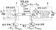
- FIG. 10 is a diagram illustrating a power loss estimation structure in a transmission/reception channel to describe a foreign matter detection function according to an embodiment of the present invention.
- FIG. 11 is a diagram showing that the mobile unit moves from the center of the transmitting coil to the center of the receiving coil of the smartphone among the internal configuration modules of the autonomous wireless charger (T) based on power loss tracking according to an embodiment of the present invention.
- FIG. 12 is a diagram illustrating an internal layout of a core module of an autonomous wireless charging system based on power loss tracking according to an embodiment of the present invention.
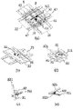
- 13 is a detailed view showing the mechanical design and configuration of the mobile device of the autonomous wireless charging system based on power loss tracking according to an embodiment of the present invention in detail, and fixedly coupled to the X-axis rack gear and the X-axis rail It is a diagram showing gears, transmission coils, ferrites, and the like.
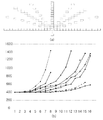
- FIG. 14 is a graph showing a distribution of power loss values according to a separation distance between a power transmission coil and a power receiving coil in a power loss tracking-based autonomous wireless charging system as an embodiment of the present invention, and a consistency of increase and decrease at a glance. It is a drawing.
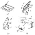
- FIG. 15 is a view showing an embodiment in which a stationary charger and a tray-type charger of an autonomous wireless charging system based on power loss tracking according to an embodiment of the present invention can be used as a pad and a rotary stand.
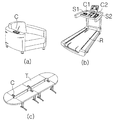
- FIG. 16 is a view showing an embodiment of a built-in form of an office and conference room desk, sofa, furniture, and treadmill infrastructure of an autonomous wireless charging system according to an embodiment of the present invention.
- FIG. 17 is a view showing an embodiment of a built-in form in a free space behind a mug cup or on the inside of a console of an autonomous wireless charging system based on power loss tracking according to an embodiment of the present invention.
- FIG. 18 is a view showing various types of embodiments, such as a charging pad for a wireless charging mouse and a smartphone and a garage and parking lot for charging an electric vehicle, in an autonomous wireless charging system based on power loss tracking according to an embodiment of the present invention.
- the present invention employs a tray-type case, the controller sets a base value or a threshold value based on the power loss value generated in the process of detecting foreign matter in the power transmitter, and is constant in the position direction detected through periodic power loss value monitoring.
- the central portion of the autonomous wireless charging system It is best to move the transmission coil only in the stroke zone that is located at and can move in the vertical direction.
- a prior art transmission coil, receiving coil alignment to move the transmitting coil toward the receiving coil to the edge of the pad using a detection circuit board of a size similar to the pad area to track the position of the wireless device located on the flat case pad It shows an example.
- a number of disadvantages are caused in terms of driving and production costs, such as the presence of a blind spot on the pad, a large moving device portion of a screw type of a method that moves relatively long distances, lack of durability, large noise, and a large number of parts. would.
- FIG. 2 shows an example of alignment of the transmission coil and the reception coil in a very small stroke zone by using a tray type wireless charger instead of a flat case pad with a large stroke zone. Therefore, because the moving distance is short, the design dimension of the motor or the mechanical part can be reduced, so it is economical, the motor capacity is spared, and there are few cases of long-distance movement, so the noise caused by motor rotation is small and the moving device using the XY guide using the slide bearing method Wealth also ensures durability to withstand moderate vibration and shock. According to the present invention, the tracking of the center of the power receiving coil based on the power loss tracking has a greater relative economical efficiency because a location tracking circuit board is not required, unlike the prior art.
- FIG. 3 shows the overall operation of the autonomous wireless charging system based on power loss tracking according to the present invention.
- the power transmission coil 2 of the mobile device 4 moves to the central position of the system located in the standby mode (S302), and communicates with the power transmission device 3 to lose power.
- sensing S303. If the sensing data value is a valid value, the moving direction of the mobile device 4 is selected (S304). At this time, the moving direction is calculated for the X-axis and the Y-axis, respectively.
- the sensing value is stored (S305), and the moving device unit 4 is moved (S306). Check whether the sensing value is valid (S307).
- the validity of the sensing data value means that the value is constantly decreased or increased, and the moving direction of the mobile device 4 is determined based on the validity. If it is valid, the mobile device 4 is stopped (S308), and if it is not, the mobile device 4 is moved (S306), and the power loss value is sensed again to continue the validity determination process. If the sensing value is not valid, the mobile device 4 is stopped (S308) and the power loss value is sensed again (S309). Check whether there is a change in the sensed power loss value (S310). If there is a change, the mobile device 4 moves to the central position (S302), and if there is no change, the mobile device 4 goes to a stopped state and then repeats the next process.
- the 4 shows the movement (S401) of the mobile device 4.
- the direction of the mobile device 4 is determined (S402). If the moving direction is determined (S403), the moving device 4 is moved a predetermined distance in the moving direction in the predetermined direction (S405), the sensing value is stored, and the virtual position value is updated (S406). If the moving direction is not determined, go to the moving device unit 4 direction selection loop (S404), calculate the moving direction (S404), check whether the moving direction is determined (S403), and decide whether or not to move a certain distance. do.
- the virtual location update means moving a certain distance to the virtual location of the mobile device 4, and is necessary to prevent overrun, stop, and return to the central location again.
- the virtual location is associated with the stroke zone.
- the virtual position is also updated if it has actually moved.
- FIG. 5 shows the operation (S501) when the mobile device unit 4 is stopped and being charged.
- the power loss value is sensed (S503) to determine whether the sensing value is valid (S505).
- the mobile device 4 is returned to its original position (S507), After updating the virtual location (S508), the mobile device 4 goes to the control (S509) step.
- FIG. 6 shows an operation of calculating the direction of the mobile device 4 (S601).
- the movement direction of the mobile device 4 is checked (S602). It is determined whether the movement direction has been determined (S603), and if the movement direction has been determined, the mobile device 4 goes to the control loop S604 to enter the movement control process. However, if the moving direction is not determined, after moving a certain distance to the right (S605), the virtual position is updated (S606). The power loss value is sensed again (S607), and it is checked whether the sensing value is reduced (S608).
- the sensing value decreases means that the power transmission coil 2 of the mobile device 4 is approaching the center of the power receiving coil R of the wireless device S, the right counter is increased (S609), and the left counter is increased.
- the right counter value is the set value (S611), select the right side if it is the set value (S612), and go again to check the movement direction of the mobile device 4 (S6012). If the setting value is not set, the mobile device 4 is moved to the right a predetermined distance (S605), the virtual position is updated (S606), and the rest of the process is repeated.
- the left counter is incremented (S613), the right counter is initialized (S614), and it is determined whether the left counter is the set value (S615). . If it is a set value, it is selected to the left (S615) and the mobile device 4 goes to check the movement direction (S602). If the setting value is not set, the mobile device 4 is moved to the right a predetermined distance (S605), the virtual position is updated (S606), and the rest of the process is repeated.
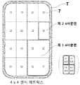
- the 7 is a wireless charging object, assuming that the smart phone (S) is randomly mounted, when the position of the smart phone (S) is displaced due to the shaking of the vehicle, etc., in one embodiment, when a matrix of 16 sensors (7) is required It shows that it can be used selectively.
- the matrix of the sensor 7 can be controlled so that the direction of which quadrant is located when the smartphone is displaced can be tracked and tracked according to implementation.
- the arrangement of the sensor 7 matrix should arrange the sensor 7 at a position that is an integer multiple of 1 mm.
- the transmission coil 2 can be moved to the final displacement position.
- This sensor (7) matrix method may be a more efficient method in calculating the direction when the sensor (7) element is expected to be cheaper and smaller in size.
- the primary side coil 2 of the power transmitter T and the secondary side coil R of the power receiver S are weakly coupled, and the primary side
- the magnetic flux of the magnetic flux is induced to the secondary coil, and the induced magnetic flux generates an electromotive force on the secondary side, so that the power has the transformer structure of the air core that is transmitted to the secondary side. It is a drawing showing that there is.
- the autonomous wireless charging system (power transmitter T) based on the power loss tracking of the present invention includes a power transmission unit 3, a mobile unit 4, and a control unit 5 Consisting of three core modules, the MCU (controller 6) in the control unit 5 controls the process and system operation such as reading the power loss value, recognizing and tracking the position, and moving and stopping the up and down, left and right of the transmission coil. Manage intensively.
- the controller 6 periodically tracks the increase and decrease of the power loss value generated by the power transmitter T in the process of detecting foreign matter, thereby precisely tracking the center position of the power receiving coil R of the power receiver S, and thus the power receiver S Even when the position of is displaced, it is controlled to move the power transmission coil 2 of the moving device 4 to the position.
- the autonomous mobile wireless charging system using one transmitting coil 2 is more convenient, effective charging efficiency, freedom, cost ratio, and versatility when compared to the existing system using one to three transmitting coils. It is a table that analyzes that it is possible to provide differentiated superior features and performance.
- the production cost increases to a certain extent by the addition of the moving device 4 and the control device 5, but it is costly to use one coil instead of using two to three coils and to reduce the ferrite area accordingly.
- the power transmitter circuit (T) using one transmission coil (2) is more stable than the products of 2-3 coils, which is advantageous in reducing product cost during mass production.
- the power loss is defined as the difference between the received power and the received power when the power transmitter T transmits power to the power receiver S.
- the power transmitter T estimates the adjusted power value by adjusting the transmitted power value and the received power value using a so-called linear interpolation method to calculate the power loss value and compares this value with the threshold value to the pad. It is determined whether the subject is a foreign object. When the object is identified as the charging object, the power transmitter T enters the power transmission step.
- the power transmitter T of the present invention that is, the controller 6 in the controller 5 of the autonomous wireless charging system based on power loss tracking 6 ) Tracks the center position of the power receiving coil R of the power receiver S and uses the power loss value of the following equation.
- the power loss is defined as the difference between the transmission power P PT and the reception power P PR
- the controller 6 transmission in the direction of the power transmitter (T) is a P loss value reduced by using a P loss value to calculate coil (2) Control the movement.
- P loss represents the power absorption of foreign objects or charged objects.
- P In is the power value given at the input of the power transmitter (T)
- P PTloss is the power value consumed by the power transmitter (T) internal circuits (inverter, transmission coil, resonant capacitor, ferrite, gold parts, etc.)
- P Out is power
- the power value given at the output terminal of the receiver, P PRloss means the power value lost inside the power receiver S.
- the power transmitter T may calculate a power loss value P loss and compare it with a threshold value.
- the mobile device 4 of the autonomous wireless charging system based on hardware and cost-efficient power loss tracking employing a tray-shaped case is located in the center of the system and moves the transmission coil 2 only in the stroke zone. do. Since it is not necessary to charge the power receivers S located in all directions from end to end in the up and down, left and right directions based on the tray type case, it is possible to move only the predetermined stroke zone in the up and down and left and right directions to move the transmission coil 2 to move time It is reasonable to shorten the shaft and charging time.
- the controller 6 moves the transmission coil 2 again in the direction of the sensed position to perform a normal charging process for the power receiver S. Lasts.
- This power receiver (S) of the receiving coil (R) finds the center position and moves.
- the mobile device 4 is located at the center of the system T.
- the power transmission coil (2) and the ferrite (1) is mounted, and the mobile unit (4) composed of an X-axis rail (21) and a Y-axis rail (22) is located at the center of the power receiver (S) where the shortest distance is placed. It is placed in the center of the system to move to.
- the free spaces A and B can solve the problem of double stacking by arranging the control unit 5 PCB and the power transmission unit 3 PCB, respectively, and make the thickness of the wireless charging device slim.
- the transmission coil 2 mounted on the mobile device 4 may be implemented by extending the connection with a flexible cable such as a transmission module and a film cable.
- the moving unit 4 for moving the coil is cross-coupled in a state in which the X-axis rail 21 and the Y-axis rail 22 are crossed by X-axis and Y-axis.
- the central portion is composed of a second slide bearing 42, an X-axis rack gear 311, an X-axis motor 31, a Y-axis motor 32, and a first slide bearing 41, and a control unit 5 It is interlocked with and shows that the controller 6 is interlocked with the power transmission device 3 and the mobile device 4.
- the Y-axis rail 22 coupled to the second slide bearing 42 according to the operation of the X-axis motor 31 moves the X-axis rail 21.
- the slider coupled to the Y-axis rail 22 according to the driving of the Y-axis motor 32 moves in the direction of the Y-axis rail 22 to reach the optimum position of wireless charging.
- the X-axis rail 21 is a device that is fixed across from one end of the lower cover 2 to the other end.
- the Y-axis rail 22 fixed and moving on the X-axis rail 21 can quickly move the power transmission coil 2 to a specific position.
- the Y-axis rail 22 formed perpendicular to the X-axis rail 21 moves the transmission coil 2 fixedly coupled to the slider in the X-axis and Y-axis directions to reach an optimal position for wireless charging.
- the Y-axis rail 22 is surrounded by a first through hole formed so that the X-axis motor 31 is wrapped inside and a Y-axis motor 32 formed perpendicular to the X-axis motor 31 is wrapped outside. It is a rail through which a second through hole is formed so as not to be visible.
- the X-axis motor 31 and the Y-axis motor 32 may be coupled to a coupling hole formed in the Y-axis rail 22, wherein the X-axis motor 31 and the Y-axis motor 32 are side surfaces.
- the area exposed to the upper part and the area exposed to the lower part of the coupling hole are the same when viewed from the area, and the area exposed to the upper part of the coupling hole is a space between the slider and the Y-axis rail 22 and the slider moves in the Y axis.
- the area exposed to the lower portion of the coupling hole is a space between the Y-axis rail 22 and the X-axis rail 21 so that the Y-axis rail 22 does not interfere with movement along the X-axis. It is installed as much as possible.
- the present invention has a specialized structure in which a driving unit (driving motor, rack and pinion) is disposed between the guide rail and the slider to obtain a blind spot and stable driving (smooth movement, noise reduction).
- a driving unit driving motor, rack and pinion
- the X-axis rack gear 311 is attached and fixed to the X-axis rail 21 according to the present invention, and is engaged with the X-axis pinion gear 313 of the X-axis motor 31.
- second slide bearings 42 are located on both sides of the X-axis rail 21.
- the X-axis motor 31 and the Y-axis motor 32 are inserted into a through hole connecting between the Y-axis rail 22 and the X-axis rail 21 that hold the position of the X-axis motor 31.
- a Y-axis motor 32 is inserted into the through-hole 320 and fixed to a coupling hole formed on the Y-axis rail 22.
- the lower end of the first slide bearing 41 made of an E-shape is coupled to both side ends of the Y-axis rail 22.
- both sides of the Y-axis rail 22 are bent in a stepwise manner so that the bent portion is inserted into the lower end of the first slide bearing 41.
- the Y-axis pinion gear 323 rotates in engagement with the Y-axis rack gear 321 of the Y-axis motor 32.
- a slider is coupled to the top shape of the "E" shape to allow the slider to move to any position along the X axis.
- the assembled X-axis rail 21 and Y-axis rail 22 described above are inserted into the lower cover, and only the X-axis rail 21 is fixed to the inner surface of the lower cover.
- the Y-axis rail 22 on the upper portion of the X-axis rail 21 can move in the X-axis direction, and after moving in any X-axis direction, the slider It can move in any Y-axis direction.
- the control unit 5 drives the mobile unit 4 in a direction in which the power loss value decreases, so that the center position of the power transmission coil 2 is centered in the power receiving coil R. Move to a location.
- the power loss value must have a consistent increase/decrease characteristic so that the mobile unit 4 can move for center alignment of the power transmission coil 2 and the power receiving coil R only by changing the power loss value without a position tracking circuit board.
- FIG. 14 sets the position of the receiving coil R as coordinates (0, 0), and transmits the coil 2 in an integer multiple of 1 mm or 1 mm in linear trajectories in 9 directions, up to 7 mm to 14 mm in the y-axis.
- 14 (a) shows the distribution of the power loss value according to the measurement direction and position, and shows that the loss value continuously increases as the separation distance between the power transmission coil 2 and the power reception coil R increases.
- 14 (b) is a graph representing the power loss value measured for a straight trajectory in nine directions. It can be seen at a glance whether the increase in the loss value shows a consistent movement (Behaviour).
- the present invention as well as a tray-type case shape that limits the mounting position of the wireless device (S), the controller 6 through the autonomous wireless charging system based on the power loss tracking, as shown in FIG.
- a wireless charging smartphone wireless charging car
- wireless charging mouse wireless charging receiver
- wireless charging receiver wireless charging receiver
- the present invention can be applied to any one of (a), (b) stationery autonomous wireless charger, (c) tray-type autonomous wireless charger (T).
- the mobile device (4) module is placed at the bottom of the charging pad part, and the control module and power transmission module PCBs are placed at the bottom of the stationery tray part with pens.
- the problem of double stacking can be solved and the thickness of the wireless charging device can be made slim.
- the present invention can be applied to any one of (a), (b), (c) office and conference room desks, furniture such as sofas, (d) treadmill, and built-in type.
- the system of the present invention is embedded in a building or furniture infrastructure, it not only provides optimal effective charging efficiency, but also creates an excellent application point in smart offices and smart furniture that can provide decisive convenience.
- the present invention provides (a), (c), (d) the right or left side of the driver's seat console or a free space behind the mug cup or (b) the vehicle's battlefield where the driver's hand and field of view can be easily reached It can be applied to any of the front consoles in the form of horizontal storage type, inclined stand type, horizontal stand type, and pocket insertion type. Incorporating the system of the present invention into various vehicle (car, SUV, truck, motorcycle, etc.) infrastructures that are susceptible to shaking creates an excellent application point of a smart car that not only provides optimal effective charging efficiency but also provides decisive convenience. .
- the present invention provides any of (a) a wireless charging mouse for a game and a charging pad for a smartphone, (b) a ground surface installation or (c) an electric vehicle charging garage and parking lot using an underground buried pad.
- Electric vehicle wireless charging system uses the same method as smartphone (S) wireless charging, so it has excellent scalability, can't see down when parking, can't match the parking line exactly, and can park approximately one time even if there's no parking hill. This has the great advantage of being able to provide optimum charging.
- the present invention after a plurality of electric vehicles parked side by side on the parking line, the stroke zone along the X-axis rail 21 and the Y-axis rail 22 of the present invention, the transmission coil 2 installed on the ground or underground.
- the transmission coil 2 and the reception coil R are on a coaxial line, thereby increasing hardware and cost efficiency of charging stations such as hardware cost reduction and power saving.
- the transmission coil 2 mounted on the mobile device 4 is connected to the transmission module by a flexible cable such as a film cable. Just implement it.
- EMI electromagnetic interference
- the sound of the engraved shape surrounding the transmission coil 2 is formed. Can be produced in shape.
- V1 Storage part and charging part
- V2 Cup holder
Landscapes
- Engineering & Computer Science (AREA)
- Power Engineering (AREA)
- Computer Networks & Wireless Communication (AREA)
- Transportation (AREA)
- Mechanical Engineering (AREA)
- Charge And Discharge Circuits For Batteries Or The Like (AREA)
Abstract
La présente invention concerne un système de charge sans fil autonome et, plus particulièrement, un boîtier de type plateau et un système de charge sans fil autonome de haute précision sur la base d'un suivi de perte de puissance, moyennant quoi, en termes de performance, la position centrale d'une bobine de réception de puissance d'un dispositif sans fil comportant une batterie montée en son sein, le dispositif sans fil étant placé en haut d'un plot de chargeur, est suivie avec précision par l'intermédiaire d'un dispositif de commande dans le système par un suivi périodique d'une différence de l'augmentation/diminution d'une valeur de perte de puissance générée pendant le processus de détection d'objet étranger d'un émetteur de puissance, et même lorsque la position du dispositif sans fil se décale, une bobine de transmission de puissance montée dans une unité de dispositif mobile est repositionnée avec précision à la position modifiée par l'intermédiaire d'une identification de valeur seuil ou, si nécessaire, par l'utilisation sélective d'une matrice de capteurs, permettant ainsi une coïncidence permanente des centres de la bobine de transmission de puissance et de la bobine de réception d'énergie, et ainsi de maintenir constant un niveau maximal de rendement de charge sans fil pendant la charge.
Priority Applications (1)
| Application Number | Priority Date | Filing Date | Title |
|---|---|---|---|
| US17/059,432 US11894697B2 (en) | 2017-12-15 | 2018-12-17 | Autonomous wireless charging system and method based on power loss tracking |
Applications Claiming Priority (3)
| Application Number | Priority Date | Filing Date | Title |
|---|---|---|---|
| KR20170173343 | 2017-12-15 | ||
| KR1020180162963A KR102081413B1 (ko) | 2017-12-15 | 2018-12-17 | 전력손실 추적 기반의 자율 무선충전 시스템 및 방법 |
| KR10-2018-0162963 | 2018-12-17 |
Publications (1)
| Publication Number | Publication Date |
|---|---|
| WO2020130162A1 true WO2020130162A1 (fr) | 2020-06-25 |
Family
ID=67065292
Family Applications (1)
| Application Number | Title | Priority Date | Filing Date |
|---|---|---|---|
| PCT/KR2018/015997 Ceased WO2020130162A1 (fr) | 2017-12-15 | 2018-12-17 | Système de charge sans fil autonome et procédé basé sur un suivi de perte de puissance |
Country Status (3)
| Country | Link |
|---|---|
| US (1) | US11894697B2 (fr) |
| KR (1) | KR102081413B1 (fr) |
| WO (1) | WO2020130162A1 (fr) |
Cited By (3)
| Publication number | Priority date | Publication date | Assignee | Title |
|---|---|---|---|---|
| CN112531917A (zh) * | 2020-11-23 | 2021-03-19 | 歌尔光学科技有限公司 | 一种无线充电接收装置和一种电子设备 |
| CN112865344A (zh) * | 2021-03-25 | 2021-05-28 | Tcl通力电子(惠州)有限公司 | 一种无线充电设备及充电方法 |
| WO2022267961A1 (fr) * | 2021-06-21 | 2022-12-29 | 长城汽车股份有限公司 | Procédé et dispositif de commande de charge sans fil, et véhicule |
Families Citing this family (12)
| Publication number | Priority date | Publication date | Assignee | Title |
|---|---|---|---|---|
| CN112152325B (zh) * | 2019-06-28 | 2023-06-20 | 北京小米移动软件有限公司 | 线圈位置调整方法、装置和存储介质 |
| KR102798351B1 (ko) * | 2020-04-28 | 2025-04-22 | 삼성전자주식회사 | 무선 전력 전송 장치 및 그 제어 방법 |
| JP7503001B2 (ja) * | 2021-01-12 | 2024-06-19 | 株式会社日立エルジーデータストレージ | 送電装置、受電装置、およびそれらを備えた送受電システム |
| KR102672326B1 (ko) | 2021-07-29 | 2024-06-05 | 한국전자통신연구원 | 무선 충전 시스템에서 영상 처리 기반 이물질 탐지 방법 및 이를 수행하는 장치 |
| CN113675955A (zh) * | 2021-08-13 | 2021-11-19 | 上海钧正网络科技有限公司 | 一种无线充电装置、方法、设备及存储介质 |
| CN114465365B (zh) * | 2022-02-22 | 2025-03-25 | Oppo广东移动通信有限公司 | 无线充电座及其控制方法 |
| US20240429753A1 (en) * | 2023-06-20 | 2024-12-26 | ohSnap, Inc. | Intermediate Receiver of Wireless Power Transfer |
| CN117197740B (zh) * | 2023-09-11 | 2026-03-31 | 广西电网有限责任公司电力科学研究院 | 无线充电区域的异物识别方法及系统 |
| KR20250171188A (ko) | 2024-05-29 | 2025-12-08 | 경문건 | 운전자 무개입 급전 패드 자동 얼라이닝 기능을 이용한 무선 충전 시스템 |
| KR20250176565A (ko) | 2024-06-12 | 2025-12-19 | 경문건 | 전기차 충전 코일의 정위치 추적과 포지션 얼라이닝이 가능한 이동식 무선 충전 시스템 |
| CN118763817B (zh) * | 2024-06-13 | 2025-03-04 | 南京邮电大学 | 一种具有空间占用且充电成本受限的无线充电调度方法 |
| TWI884100B (zh) * | 2024-10-21 | 2025-05-11 | 國立虎尾科技大學 | 異物位置偵測裝置及其偵測方法 |
Citations (5)
| Publication number | Priority date | Publication date | Assignee | Title |
|---|---|---|---|---|
| KR20110034773A (ko) * | 2009-09-29 | 2011-04-06 | 삼성전자주식회사 | 유도성 결합 방식을 이용한 무선 충전기 |
| KR20120117262A (ko) * | 2011-04-15 | 2012-10-24 | 현대자동차주식회사 | 코일의 위치 정렬이 가능한 차량용 무선전력전송기 |
| KR101250290B1 (ko) * | 2012-03-06 | 2013-04-03 | 주식회사 삼광 | 코일 이동형 무선 충전기 |
| KR20170019629A (ko) * | 2015-08-12 | 2017-02-22 | 현대자동차주식회사 | 무선 전력 송신기의 제어 방법과 이를 적용한 무선 충전 시스템 |
| KR20170140734A (ko) * | 2016-06-13 | 2017-12-21 | 엘지이노텍 주식회사 | 이물질 검출 방법 및 그를 위한 장치 및 시스템 |
Family Cites Families (35)
| Publication number | Priority date | Publication date | Assignee | Title |
|---|---|---|---|---|
| JP4034800B2 (ja) | 2005-10-31 | 2008-01-16 | 東京コイルエンジニアリング株式会社 | ソーラ式携帯充電器 |
| KR100877646B1 (ko) | 2007-03-05 | 2009-01-09 | 엘에스전선 주식회사 | 복수의 코일 패드를 구비한 무 접점 충전기 및 이를 구비한배터리 충전 세트 |
| JP5362330B2 (ja) | 2007-12-18 | 2013-12-11 | 三洋電機株式会社 | 充電台 |
| DE112010002338T5 (de) * | 2009-06-25 | 2012-08-02 | Tanashin Denki Co., Ltd. | Zweidimensionale Verschiebeeinrichtung |
| JP2011217571A (ja) | 2010-04-01 | 2011-10-27 | Sanyo Electric Co Ltd | 電池パック用充電器 |
| KR101261267B1 (ko) | 2010-08-10 | 2013-05-07 | 김광식 | 무접점 충전기용 코일 및 이 코일을 제조하기 위한 권선 용구 |
| KR20120090240A (ko) * | 2011-02-07 | 2012-08-17 | 주식회사 팬택 | 전자 장치 무접점 충전 시스템 및 방법 |
| JP5666997B2 (ja) | 2011-06-21 | 2015-02-12 | タナシン電機株式会社 | コイル移動型無接点充電器 |
| JP5781392B2 (ja) | 2011-07-28 | 2015-09-24 | 三洋電機株式会社 | 電池パック及び電池駆動機器並びに電池パックの無接点充電方法 |
| JP6185472B2 (ja) | 2011-09-09 | 2017-08-23 | ワイトリシティ コーポレーションWitricity Corporation | ワイヤレスエネルギー伝送システムにおける異物検出 |
| HK1200602A1 (en) | 2011-11-04 | 2015-08-07 | WiTricity公司 | Wireless energy transfer modeling tool |
| KR101368771B1 (ko) | 2012-08-07 | 2014-03-03 | (주)디팜스 | 무선충전기용 tx 3코일 덮개 |
| US9666357B2 (en) | 2012-09-11 | 2017-05-30 | Qualcomm Incorporated | Apparatus system, and method for wirelessly receiving power using conductive structures |
| US9148033B2 (en) * | 2012-12-21 | 2015-09-29 | Ford Global Technologies, Llc | System of securing a wide-range of devices during wireless charging |
| EP2793359A4 (fr) * | 2013-03-06 | 2015-12-02 | Hanshinkijeon Co Ltd | Chargeur sans fil apte à un réglage de position automatique et procédé de charge l'utilisant |
| KR101963261B1 (ko) * | 2013-03-22 | 2019-03-28 | 삼성전기주식회사 | 무선 충전 장치 |
| JP6178976B2 (ja) | 2013-05-31 | 2017-08-16 | パナソニックIpマネジメント株式会社 | 携帯端末充電装置と、それを用いた自動車 |
| US10014711B2 (en) * | 2013-10-21 | 2018-07-03 | Panasonic Intellectual Property Management Co., Ltd. | Mobile terminal charging device and automobile using same |
| KR102097497B1 (ko) * | 2013-12-13 | 2020-05-27 | 엘지전자 주식회사 | 이동단말기 무선충전기 |
| KR101491378B1 (ko) * | 2013-12-20 | 2015-02-06 | 현대자동차주식회사 | 휴대장치의 무선충전을 수행하는 멀티미디어 장치의 조작 장치 및 방법 |
| US10295693B2 (en) | 2014-05-15 | 2019-05-21 | Witricity Corporation | Systems, methods, and apparatus for foreign object detection loop based on inductive thermal sensing |
| US20160064943A1 (en) * | 2014-08-28 | 2016-03-03 | Konkuk University Industrial Cooperation Corp. | Controlling method and system of power transmission system |
| KR20160028262A (ko) * | 2014-09-03 | 2016-03-11 | 에스엘 주식회사 | 차량용 콘솔 어셈블리 |
| KR101701054B1 (ko) | 2015-06-12 | 2017-01-31 | 삼성전기주식회사 | 차량용 무선 충전 장치 |
| KR101704264B1 (ko) * | 2015-09-22 | 2017-02-07 | 현대자동차주식회사 | 자동 정렬 기능을 가지는 무선 충전 장치 및 그 방법 |
| KR20170041389A (ko) * | 2015-10-07 | 2017-04-17 | 엘지이노텍 주식회사 | 무선 충전 디바이스 정렬 안내 방법 및 그를 위한 장치 및 시스템 |
| CN115208079A (zh) * | 2016-09-21 | 2022-10-18 | 苹果公司 | 无线充电垫上的对象位置和取向的检测 |
| KR102548384B1 (ko) * | 2017-03-07 | 2023-06-27 | 파워매트 테크놀로지스 엘티디. | 무선 전력 충전 시스템 |
| CN109149794B (zh) * | 2017-06-28 | 2020-11-17 | 金宝电子工业股份有限公司 | 无线充电系统与无线充电方法 |
| US10566822B2 (en) * | 2017-07-28 | 2020-02-18 | Toyota Motor Engineering & Manufacturing North America, Inc. | Providing a movable charging coil |
| US11005309B2 (en) * | 2018-01-26 | 2021-05-11 | Wbtec, Llc | Charging apparatus with locator |
| US10742074B2 (en) * | 2018-06-15 | 2020-08-11 | Lg Innotek Co., Ltd. | Method and apparatus for controlling wireless power transmission |
| US11342796B2 (en) * | 2018-09-07 | 2022-05-24 | Google Llc | Controlling wireless charging |
| EP3944508B1 (fr) * | 2020-07-23 | 2023-11-08 | ElectDis AB | Dispositif de test pour tester un dispositif de puissance sans fil et procédé associé |
| KR102882243B1 (ko) | 2022-01-05 | 2025-11-06 | 엘지전자 주식회사 | 의류처리장치 |
-
2018
- 2018-12-17 WO PCT/KR2018/015997 patent/WO2020130162A1/fr not_active Ceased
- 2018-12-17 KR KR1020180162963A patent/KR102081413B1/ko active Active
- 2018-12-17 US US17/059,432 patent/US11894697B2/en active Active
Patent Citations (5)
| Publication number | Priority date | Publication date | Assignee | Title |
|---|---|---|---|---|
| KR20110034773A (ko) * | 2009-09-29 | 2011-04-06 | 삼성전자주식회사 | 유도성 결합 방식을 이용한 무선 충전기 |
| KR20120117262A (ko) * | 2011-04-15 | 2012-10-24 | 현대자동차주식회사 | 코일의 위치 정렬이 가능한 차량용 무선전력전송기 |
| KR101250290B1 (ko) * | 2012-03-06 | 2013-04-03 | 주식회사 삼광 | 코일 이동형 무선 충전기 |
| KR20170019629A (ko) * | 2015-08-12 | 2017-02-22 | 현대자동차주식회사 | 무선 전력 송신기의 제어 방법과 이를 적용한 무선 충전 시스템 |
| KR20170140734A (ko) * | 2016-06-13 | 2017-12-21 | 엘지이노텍 주식회사 | 이물질 검출 방법 및 그를 위한 장치 및 시스템 |
Cited By (4)
| Publication number | Priority date | Publication date | Assignee | Title |
|---|---|---|---|---|
| CN112531917A (zh) * | 2020-11-23 | 2021-03-19 | 歌尔光学科技有限公司 | 一种无线充电接收装置和一种电子设备 |
| CN112531917B (zh) * | 2020-11-23 | 2022-12-09 | 歌尔光学科技有限公司 | 一种无线充电接收装置和一种电子设备 |
| CN112865344A (zh) * | 2021-03-25 | 2021-05-28 | Tcl通力电子(惠州)有限公司 | 一种无线充电设备及充电方法 |
| WO2022267961A1 (fr) * | 2021-06-21 | 2022-12-29 | 长城汽车股份有限公司 | Procédé et dispositif de commande de charge sans fil, et véhicule |
Also Published As
| Publication number | Publication date |
|---|---|
| US11894697B2 (en) | 2024-02-06 |
| KR102081413B1 (ko) | 2020-02-25 |
| US20210218289A1 (en) | 2021-07-15 |
| KR20190072484A (ko) | 2019-06-25 |
Similar Documents
| Publication | Publication Date | Title |
|---|---|---|
| WO2020130162A1 (fr) | Système de charge sans fil autonome et procédé basé sur un suivi de perte de puissance | |
| KR102097497B1 (ko) | 이동단말기 무선충전기 | |
| US20160111913A1 (en) | Wirelessly rechargeable battery and power transmitter | |
| US20160072334A1 (en) | Wireless charging device and method thereof | |
| EP2258032A2 (fr) | Positionnement magnétique pour couplage inductif | |
| KR20110034773A (ko) | 유도성 결합 방식을 이용한 무선 충전기 | |
| CN105515224A (zh) | 为电动车充电的移动充电装置及其充电系统 | |
| CN210273564U (zh) | 无线充电底座 | |
| CN102882243A (zh) | 线圈移动型无接点充电器 | |
| WO2017204447A1 (fr) | Appareil et procédé de charge sans fil | |
| WO2016195145A1 (fr) | Système de charge sans fil de type à boîtiers multiples pour la charge simultanée de multiples dispositifs mobiles | |
| CN109742827A (zh) | 无线充电装置及无线充电装置的控制方法 | |
| KR102300573B1 (ko) | 틸트 기능을 이용하여 다수의 사용자 단말을 동시에 충전하는 무선 충전 장치 | |
| WO2016114629A1 (fr) | Dispositif de transmission de puissance sans fil | |
| KR101659215B1 (ko) | 무선 충전기 | |
| JP2013121258A (ja) | 非接触電力伝送装置 | |
| KR20190092203A (ko) | 하드웨어 및 비용 효율이 높은 자율 무선충전 장치 | |
| KR102155678B1 (ko) | 모터 스크루 커플링 기반 무선충전용 송전 코일 이동 시스템 | |
| CN112467884A (zh) | 无线充电设备、系统以及方法 | |
| WO2023068702A1 (fr) | Module de charge et de décharge sans fil ayant une fonction de charge | |
| KR102924153B1 (ko) | 범용 무선 충전 표면 | |
| KR20220118298A (ko) | 사용자 단말을 다양한 방향 및 각도로 거치할 수 있는 무선 충전 장치 | |
| CN207955386U (zh) | 移动充电平台 | |
| US20230361602A1 (en) | Wireless power transmission to a mobile device | |
| WO2019117488A1 (fr) | Dispositif d'alignement central de téléphone mobile pour chargement sans fil dans un véhicule |
Legal Events
| Date | Code | Title | Description |
|---|---|---|---|
| 121 | Ep: the epo has been informed by wipo that ep was designated in this application |
Ref document number: 18943520 Country of ref document: EP Kind code of ref document: A1 |
|
| NENP | Non-entry into the national phase |
Ref country code: DE |
|
| 122 | Ep: pct application non-entry in european phase |
Ref document number: 18943520 Country of ref document: EP Kind code of ref document: A1 |