EP3758568B1 - Saugdüse und tragbares hartflächenabsauggerät - Google Patents
Saugdüse und tragbares hartflächenabsauggerät Download PDFInfo
- Publication number
- EP3758568B1 EP3758568B1 EP18707365.5A EP18707365A EP3758568B1 EP 3758568 B1 EP3758568 B1 EP 3758568B1 EP 18707365 A EP18707365 A EP 18707365A EP 3758568 B1 EP3758568 B1 EP 3758568B1
- Authority
- EP
- European Patent Office
- Prior art keywords
- housing
- fixing part
- suction nozzle
- lip
- suction
- Prior art date
- Legal status (The legal status is an assumption and is not a legal conclusion. Google has not performed a legal analysis and makes no representation as to the accuracy of the status listed.)
- Active
Links
Images


Classifications
-
- A—HUMAN NECESSITIES
- A47—FURNITURE; DOMESTIC ARTICLES OR APPLIANCES; COFFEE MILLS; SPICE MILLS; SUCTION CLEANERS IN GENERAL
- A47L—DOMESTIC WASHING OR CLEANING; SUCTION CLEANERS IN GENERAL
- A47L1/00—Cleaning windows
- A47L1/02—Power-driven machines or devices
- A47L1/05—Hand apparatus with built-in electric motors
-
- A—HUMAN NECESSITIES
- A47—FURNITURE; DOMESTIC ARTICLES OR APPLIANCES; COFFEE MILLS; SPICE MILLS; SUCTION CLEANERS IN GENERAL
- A47L—DOMESTIC WASHING OR CLEANING; SUCTION CLEANERS IN GENERAL
- A47L7/00—Suction cleaners adapted for additional purposes; Tables with suction openings for cleaning purposes; Containers for cleaning articles by suction; Suction cleaners adapted to cleaning of brushes; Suction cleaners adapted to taking-up liquids
- A47L7/0004—Suction cleaners adapted to take up liquids, e.g. wet or dry vacuum cleaners
- A47L7/0019—Details of the casing
Definitions
- the invention relates to a suction nozzle for a portable hard surface suction device for removing and sucking off a liquid from a hard surface, in particular from a window pane, with a housing which has a suction opening on a housing front side, which is connected to a suction channel which can be connected to a vacuum source. and with an elastically deformable pull-off lip, which is exchangeably held on the front side of the housing.
- the invention relates to a portable hard surface suction device with such a suction nozzle.
- a suction nozzle and a portable hard surface suction device for scraping and sucking a liquid from a hard surface are from the publication DE 20 2008 018 112 U1 known. They are used in particular to clean window panes, but also to clean other hard surfaces, such as shower cubicle walls, glass doors or tiled walls.
- the suction nozzle has a housing with a housing end face on which a suction opening is arranged.
- a suction channel connects to the suction opening, which can be connected to a negative pressure source of the portable hard surface suction device.
- An elastically deformable pull-off lip is exchangeably held on the front side of the housing and protrudes forwards out of the front side of the housing in the direction away from the suction channel.
- the portable hard surface suction device can be moved along the hard surface with the replaceable squeegee in the manner of a manual window squeegee, so that liquid can be drawn off the hard surface by means of the squeegee.
- the liquid collects at the suction opening of the suction nozzle and a mixture of liquid and air can be sucked out of the suction opening.
- the portable hard surface suction device has a suction unit that is flow-connected to the suction nozzle.
- the separated liquid can be collected in a liquid tank of the portable hard surface suction device, which can be emptied if necessary.
- the extracted air can be discharged from the suction unit to the surroundings of the hard surface suction device.
- the suction nozzle can have an elastically deformable support lip, which is also arranged on the front side of the housing and is covered by the lip.
- the squeegee lip is subject to a certain amount of wear, especially when removing liquid from tiled walls, and should therefore be replaced from time to time.
- U1 known pull-off lip has a thickened area at its rear end that penetrates into the housing, which extends from a first side edge of the pull-off lip to a second side edge and which is received in a form-fitting manner by a receiving channel of the housing aligned parallel to the front side of the housing.
- the pull-off lip can be pulled out of the side of the housing and a new pull-off lip can be pushed into the side of the housing, with the thickening dipping into the receiving channel.
- this requires a high dimensional accuracy of the receiving channel and the thickening.
- replacing the pull-off lip requires a certain level of skill on the part of the user and is often not readily apparent to the user.
- a suction nozzle with the features of the preamble of claim 1 is from EP 3 195 780 A1 known.
- the object of the present invention is therefore to further develop a suction nozzle of the type mentioned at the outset in such a way that the extractor lip can be replaced more easily without the extractor lip and the housing having to have very high dimensional accuracy.
- the suction nozzle according to the invention has a fixing part for fixing the exchangeable pull-off lip on the front side of the housing.
- the locking member is reciprocally movable relative to the housing between a pull-lip locking position (locking position) and a pull-lip releasing position (release position).
- the replaceable pull-off lip can be fixed to the front of the housing with the help of the fixing part.
- the user can move the fixing part into the fixing position.
- the locking part In order to separate the peel-off lip from the housing, the user can move the locking part into a release position in which the locking part releases the peel-off lip. In the release position, the fixing part does not represent an obstacle for the pull-off lip, so that it can be easily separated from the housing.
- Such a configuration makes it easier for the user to replace the pull-off lip, since he only has to move the fixing part from the fixed position into a release position in order to then remove the pull-off lip from the housing. The user can then position another pull-off lip on the housing and then transfer the fixing part back into its fixed position, so that the new pull-off lip is then fixed to the housing by means of the fixing part.
- the fixing part is slidable along an outside of the housing of the suction nozzle.
- the fixing part can be displaced relative to the housing.
- the fixing part can be moved back and forth between the fixed position and the release position without tools. This makes it easier for the user to replace the pull-off lip, since no tools are required for this.
- the user can move the retainer from the retainer position to a release position without tools, then replace the tear lip, and then move the retainer back to the retainer position without tools.
- the housing preferably has a supporting edge on the front side of the housing, on which a rear end section of the pull-off lip can be positioned, and the fixing part has a holding strip which can be positioned on the rear end section of the pull-off lip.
- This makes it possible to fix the pull-off lip to the housing in that its rear end section occupies a position between the supporting edge of the housing and the holding strip of the fixing part.
- the support edge can form a bearing surface for the rear end section of the pull-off lip and thereby support the pull-off lip, and the holding strip can at least partially cover the rear end section of the pull-off lip.
- the holding strip extends from a first side edge of the pull-off lip to a second side edge of the pull-off lip.
- the rear end section of the pull-off lip can be completely covered by the retaining strip between the side edges of the pull-off lip. This enables the pull-off lip to be fixed to the housing with high mechanical loads.
- the rear end section of the pull-off lip and the supporting edge of the housing have projections which are aligned at an angle to a longitudinal axis of the suction nozzle and which engage behind one another.
- the projections that engage behind one another ensure that the pull-off lip cannot easily be pulled forwards, that is to say in the direction away from the suction channel, out of the housing.
- the projections that engage behind one another are aligned at an angle to the longitudinal axis of the suction nozzle.
- an alignment of the projections perpendicular to the longitudinal axis of the suction nozzle has proven to be advantageous.
- the projections can extend perpendicularly to the longitudinal axis along the entire rear end portion of the peel-off lip and along the entire support edge of the housing.
- the fixing part can advantageously be releasably connected to the housing.
- the fixing part forms a force or form fit with the housing in the fixed position and can be moved into the release position if necessary.
- the fixing part can be releasably connected to the housing without tools.
- the user does not need a tool to connect the fixing part to the housing and to release the connection again if necessary.
- the fixing part preferably has at least one first latching element which, in the fixing position, engages behind a second latching element arranged on the housing.
- the at least one first latching element is arranged on a rear side of the fixing part and if the at least one second latching element is arranged on an end section of the suction channel protruding from a rear side of the housing.
- the suction channel extending through the housing has an end section protruding from the rear side of the housing.
- This end section can, for example, be configured so that it can be plugged into a base body of the portable hard surface suction device.
- the end section of the suction channel can be inserted into an inlet channel of the base body to establish a flow connection between the suction nozzle and the suction unit of the hard surface suction device.
- the locking connection between the fixing part and the housing takes place. If the user separates the suction nozzle from the main body of the hard surface suction device, then the end section of the suction nozzle protruding from the rear of the housing is his accessible to the suction channel and he can easily release the latching connection between the at least one first latching element, which is arranged on the rear side of the fixing part, and the at least one second latching element, which is arranged at the end section of the suction channel, in order to move the fixing part into a release position move in which the pull-off lip can be separated from the housing.
- the fixing part can be separated from the housing. This allows the locking part to be completely separated from the body of the suction nozzle in order to replace the lip.
- the fixing part can have a flat configuration.
- the fixing part at least partially covers an outside of the housing in the fixing position.
- the fixing part is arranged on an outside of the housing in the fixing position, and the outside is at least partially covered by the fixing part.
- the fixing part has a cover plate which at least partially covers an outside of the housing when the fixing part is in the fixed position.
- the housing preferably has a receptacle on an outside, into which the fixing part can be inserted.
- the fixing part can initially be displaced along an outside of the housing and can then be separated from the housing.
- the fixing part can be subjected to a holding force directed at the housing by the housing in the fixed position.
- the fixing part is subjected to a force in the direction of the housing in the fixing position.
- Such a configuration is particularly advantageous when a rear end section of the pull-off lip assumes a position between the housing and the fixing part, because by subjecting the fixing part to a holding force in the direction of the housing, it can be ensured in a structurally simple manner that the between rear end portion of the peel-off lip arranged between the fixing part and the housing cannot easily be moved forward in the direction away from the suction channel.
- the fixing part preferably has first holding elements which, in the fixing position of the fixing part, can be acted upon by second holding elements arranged stationarily on the housing with a holding force in the direction of the housing.
- the first and second holding elements can together form a linear guide for moving the fixing part relative to the housing.
- the first and second holding elements in such an embodiment of the invention have a guiding function in that they form a linear guide for the fixing part, so that the fixing part relative to the housing can be moved.
- the first and/or second holding elements are advantageously designed in the form of ribs or L-shape.
- the housing has guide openings into which a first holding element can be inserted, with a second holding element being arranged inside the housing in alignment with the guide openings.
- the first holding elements of the fixing part can each be inserted into a guide opening in the housing and then come to rest against a second holding element of the housing, so that a holding force is then applied to the fixing part, starting from the housing, via the first and second holding elements can be exercised.
- the guide openings are preferably arranged on an end wall of the housing, on the outside of which the pull-off lip is connected.
- the housing can form a support edge on which a rear end section of the pull-off lip can be positioned, which in turn can be covered at least in regions by a retaining strip of the fixing part.
- the housing of the suction nozzle preferably has two housing half-shells which form the suction channel between them.
- the two housing half-shells can be connected to one another by means of connecting screws, the connecting screws being able to be covered by the fixing part when the fixing part is in the fixed position.
- the pull-off lip has a longitudinal section protruding forward from the front side of the housing in the direction away from the suction channel, which is adjoined by a free end section that is inclined toward the longitudinal section in the non-deformed basic position of the pull-off lip.
- the pull-off lip has, for example, an L-shaped profile with a first leg, which forms the longitudinal section, and with a second leg, which is aligned obliquely or perpendicularly to the first leg and forms the forms free end section.
- the free end section can be made significantly shorter than the longitudinal section, so that the profile of the pull-off lip is essentially hook-shaped.
- the suction nozzle can have a supporting lip arranged on the front side of the housing in addition to the replaceable pull-off lip.
- its free end section can extend beyond the free end of the support lip and form a scraper lip edge that can be placed against the hard surface to be cleaned.
- the pull-off lip is reinforced, particularly in its edge regions.
- the pull-off lip has at least one reinforcing rib on its upper side facing away from the supporting lip.
- the pull-off lip has a side edge on each of its longitudinal sides. It is favorable if at least one reinforcing rib is arranged at a distance from each side edge. In particular, it can be provided that two reinforcing ribs running parallel to the side edge are positioned at a distance from each side edge.
- the invention relates not only to a suction nozzle but also to a portable hard surface suction device with a suction nozzle, as explained in more detail above.
- the portable hard-surface suction device is preferably designed as a hand-held device that the user can carry with one hand and move along a hard surface, in particular a window pane, in the manner of a manual window squeegee.
- the portable hard surface suction device has a suction unit which is flow-connected to the suction nozzle stands for suction of a liquid-air mixture from the hard surface.
- the portable hard surface suction device has a separating device, which is arranged in the flow path between the suction nozzle and the suction unit for separating liquid from the suctioned liquid-air mixture.
- the portable hard surface suction device has a liquid tank for receiving the separated liquid.
- a suction flow can be generated at the suction opening of the suction nozzle, under the effect of which a mixture of liquid and air can be sucked into the suction channel.
- the liquid sucked in can be separated from the mixture of liquid and air with the aid of the separating device and transferred to the liquid tank.
- the air sucked in can be discharged to the environment via air outlet openings of the portable hard surface suction device.
- FIG. 1 and 2 an advantageous embodiment of a portable hard surface suction device according to the invention is shown schematically, which is assigned the reference numeral 10 overall.
- the hard surface suction device has an advantageous embodiment of a suction nozzle 12 according to the invention, which is Figures 3 to 16 is shown schematically.
- liquid can be drawn off and sucked off a hard surface, for example from a window pane.
- the hard surface suction device 10 can be moved along the hard surface by the user in the manner of a manual window squeegee.
- the portable hard surface suction device 10 forms in particular a window cleaning device.
- the hard surface suction device 10 comprises a basic body 14 with a basic housing 16 which forms a handle 18 and surrounds a suction unit 20 .
- the suction unit 20 has a suction turbine 22 which is driven by an electric motor 24 .
- the electric motor 24 is supplied with electrical energy by a rechargeable battery 26 arranged inside the handle 18 and can be switched on and off by the user by means of a switch 28 arranged on the handle.
- the basic housing 16 forms a separating chamber 30 in which a separating device 32 , for example a baffle wall, is arranged and which can be subjected to negative pressure by the suction unit 20 .
- the separation chamber 30 is flow-connected to a liquid tank 34 via a liquid outlet, not shown in the drawing, which is detachably held on the basic housing 16 .
- the suction nozzle 12 adjoins the base body 14 on the upper side and can be plugged into the base body 14 .
- the suction nozzle 12 has a housing 36 which is formed by a first housing half-shell 38 and a second housing half-shell 40 .
- the two housing half-shells 38, 40 are screwed together by means of connecting screws 42. This is in particular from the figures 5 and 12 clearly.
- a suction opening 46 is arranged on a housing end face 44 of the housing 36 facing away from the base body 14 and is connected to a suction channel 48 .
- the suction channel 48 extends through the housing 36 and protrudes with a rear end section 50 from a rear side 52 of the housing 36 .
- the rear end section 50 is surrounded by a sealing ring 54 and can be inserted into an inlet channel 56 of the main housing 16 to create a liquid-tight and flow-tight connection between the suction nozzle 12 and the suction unit 20.
- An exchangeable pull-off lip 58 and a supporting lip 60 are arranged on the housing end face 44 of the suction nozzle 12 .
- the pull-off lip 58 and the support lip 60 are elastically deformable.
- the support lip 60 is integrally connected to the second housing half-shell 40 .
- the supporting lip 60 is molded onto the second half-shell 40 of the housing.
- the supporting lip 60 forms an injection-molded part made of two components, the supporting lip 60 forming a soft component of the injection-molded part and the second housing half-shell 40 forming a hard component of the injection-molded part.
- the pull-off lip 58 and the supporting lip 60 protrude forward out of the housing 36 in the direction away from the suction channel 48 .
- the pull-off lip 58 engages behind the free end 62 of the supporting lip 60. It has a longitudinal section 64 adjoining the housing end face 44, which is adjoined by a front end section 66 which is inclined relative to the longitudinal section 64.
- the front end section 66 has a pull-off lip edge 68 which is arranged in front of the free end 62 of the supporting lip 60 in the undeformed basic position shown in the drawing. This is made out in particular figure 5 clearly.
- a rear end section 70 of the pull-off lip 58 which rests on a supporting edge 72 , adjoins the longitudinal section 64 .
- the supporting edge 72 is formed by the first housing half-shell 38 and connects to an end wall 74 of the first housing half-shell 38 at the front.
- the supporting edge 72 On its upper side 76 facing away from the second housing half-shell 40, the supporting edge 72 has a projection 78 with a V-shaped cross section, which extends perpendicularly to a longitudinal axis 80 of the suction nozzle 12 from a first side edge 86 of the stripping lip 58 to a second side edge 88 of the stripping lip of the entire support edge 72 extends.
- the rear end section 70 of the pull-off lip 58 has on its underside 82 facing the supporting edge 72 a projection 84 which engages behind the projection 78 of the supporting edge 72 and extends perpendicularly to the longitudinal axis 80 over the entire rear end section 70 .
- the side edges 86 and 88 of the stripping lip 58 are aligned parallel to the longitudinal axis 80 of the suction nozzle 12 .
- the suction nozzle 12 has a fixing part 100, which serves to fix the replaceable stripping lip 58 on the housing 36.
- the fixing part 100 is relative to the housing 36 between a in the Figures 3 to 9 shown fixing position and one in the Figures 10 to 13 shown release position movable back and forth.
- the fixing part 100 can be completely separated from the housing 36, as shown in FIGS Figures 10 to 13 is shown and is releasably connectable to the housing 36 .
- the fixing part 100 has a holding bar 102 which is in the fixed position of the fixing part 100 extends from the first side edge 86 to the second side edge 88 and rests on the rear end section 70 of the replaceable pull-off lip 58, so that the pull-off lip 58 cannot be pulled forwards out of the area between the holding strip 102 and the supporting edge 72 of the housing 36 .
- the first housing half-shell 38 On its upper side facing away from the second housing half-shell 40 , the first housing half-shell 38 has a receptacle 104 which is delimited by a first receiving edge 106 of the first housing half-shell 38 and a second receiving edge 108 of the first housing half-shell 38 .
- the two receiving edges 106, 108 surround the upper-side receptacle 104 of the first housing half-shell 38.
- the receiving edges 106 and 108 each have a front edge region 107 and 109, respectively, which extends forward beyond the receptacle 104 to the free end of the supporting edge 72.
- the support edge 72 is thus delimited laterally by the edge regions 107, 109 of the receiving edges 106, 108.
- the rear end section 70 of the replaceable pull-off lip 58 can be inserted between the edge regions 107, 109 of the receiving edges 106, 108 and positioned on the supporting edge 72.
- the edge regions 107, 109 form stop surfaces for the replaceable pull-off lip 58, so that it cannot move transversely to the longitudinal axis 80.
- the fixing part 100 can be inserted into the upper-side receptacle 104 of the first housing half-shell 38, completely filling the receptacle 104 in its fixed position.
- the fixing part 100 forms a cover plate 110 which covers the receptacle 104 .
- fastening part 100 On its rear side 112 facing away from retaining strip 102, fastening part 100 has an elastically deformable latching hook 114 which, in the fastening position, dips into a latching receptacle 116 formed by first housing half-shell 38 in the region of rear end section 50 of suction channel 48, thereby engaging a cross brace 118 of the first Housing half-shell 38 engages behind.
- latching receptacle 116 formed by first housing half-shell 38 in the region of rear end section 50 of suction channel 48, thereby engaging a cross brace 118 of the first Housing half-shell 38 engages behind.
- the fixing part 100 On its underside 120 facing the first housing half-shell 38, the fixing part 100 carries a plurality of first holding elements 122 which are arranged at a distance from one another and are each configured in an L-shape. In the fixed position of the fixing part 100, the first holding elements 122 each engage behind a rib-shaped or L-shaped second holding element 124, which is arranged on a bottom wall 128 of the receptacle 104. This is in particular from the Figures 7 to 9 clearly.
- the bottom wall 128 is formed by the first housing half-shell 38 and has a depression 130 in the middle, which is bridged by the cross brace 118 in the region of the rear end section 50 of the suction channel 48 .
- the latching hook 114 first enters the recess 130 .
- the fixing part 100 can then be pushed backwards along the bottom wall 128, with the first holding elements 122 arranged on the underside 120 of the fixing part 100 each plunging into a guide opening 132 in the end wall 74, which is adjoined by a second holding element 124 in each case.
- the fixing part 100 can then be pushed back along the bottom wall 128 until the latching hook 114 snaps into the latching receptacle 116 of the first housing half-shell 38 and at the same time the cover plate 110 of the fixing part 100 comes to rest on the receptacle edges 106 and 108.
- the first holding elements 122 in combination with the second holding elements 124 form a linear guide for the fixing part 100 so that the fixing part 100 can be displaced along the bottom wall 128 without the risk of the fixing part 100 tilting.
- the first holding elements 122 which are L-shaped in cross section, engage behind the second holding elements 124 when the fastening part 100 is displaced along the bottom wall 128, with the fastening part 100 being subjected to a holding force by the first housing half-shell 38 via the second holding elements 124 and the first holding elements 122.
- the fixing part 100 is pressed against the first half-shell 38 of the housing becomes.
- the retaining strip 102 is pressed against the rear end section 50 of the peel-off lip.
- the replaceable pull-off lip 58 can be fixed on the housing 36 of the suction nozzle 12 with the aid of the fixing part 100 .
- the fixing part 100 assumes its fixing position, in which the holding strip 102 of the fixing part 100 covers the rear end section 70 of the replaceable pull-off lip 58 so that the pull-off lip 58 is fixed to the housing 36 .
- the interaction of the holding strip 102 with the rear end section 70 of the pull-off lip 58 and the supporting edge 72 in the fixed position is in figure 14 illustrated.
- the user can - after separating the suction nozzle 12 from the base body 14 of the hard surface suction device - push the latching hook 114 out of the latching receptacle 116 and then insert the fixing part 100 into the in figure 14 Move forwards in the direction illustrated by the arrow 138, so that the first holding elements 122 emerge from the guide openings 132 and the fixing part 100 can then be completely separated from the housing 36 of the suction nozzle 12. This is in figure 15 illustrated. The user can then easily remove the pull-off lip 58 from the supporting edge 72 of the first housing half-shell 38, as is shown in figure 16 is illustrated.
- a pull-off lip 58 is fixed to the housing 36 in the reverse order, in which the pull-off lip 58 is first positioned with its rear end section 70 on the supporting edge 72 and then the fixing part 100 is connected to the housing 36 by first moving the latching hook 114 to the central Recess 130 of the bottom wall 128 is used and then the fixing part is moved along the bottom wall 128 in its fixing position.
- the suction nozzle 12 can be plugged into the base body 14 of the hard surface suction device 10 .
- the rear end section 50 of the suction channel 48 can be inserted into the inlet channel 56 of the basic housing 16 .
- a further latching hook 134 on the underside 136 of the second housing half-shell facing away from the first housing half-shell 38 40 is arranged, the suction nozzle 12 can be latched to the base housing 16.
- the additional latching hook 136 can engage in an opening (not shown in the drawing) in the base housing 16, and to remove the suction nozzle 12 from the base body 16, the user can actuate the additional latching hook 136 so that the latched connection between the suction nozzle 12 and the base housing 16 is released .
Landscapes
- Nozzles For Electric Vacuum Cleaners (AREA)
Description
- Die Erfindung betrifft eine Saugdüse für ein tragbares Hartflächenabsauggerät zum Abziehen und Absaugen einer Flüssigkeit von einer Hartfläche, insbesondere von einer Fensterscheibe, mit einem Gehäuse, das an einer Gehäusestirnseite eine Saugöffnung aufweist, an die sich ein Saugkanal anschließt, der an eine Unterdruckquelle anschließbar ist, und mit einer elastisch verformbaren Abziehlippe, die an der Gehäusestirnseite auswechselbar gehalten ist.
- Außerdem betrifft die Erfindung ein tragbares Hartflächenabsauggerät mit einer derartigen Saugdüse.
- Eine Saugdüse und ein tragbares Hartflächenabsauggerät zum Abziehen und Absaugen einer Flüssigkeit von einer Hartfläche sind aus der Veröffentlichung
DE 20 2008 018 112 U1 bekannt. Sie kommen insbesondere zur Reinigung von Fensterscheiben zum Einsatz, aber auch zur Reinigung anderer Hartflächen, beispielsweise Duschkabinenwänden, Glastüren oder gefliester Wände. Die Saugdüse weist ein Gehäuse auf mit einer Gehäusestirnseite, an der eine Saugöffnung angeordnet ist. An die Saugöffnung schließt sich ein Saugkanal an, der an eine Unterdruckquelle des tragbaren Hartflächenabsauggeräts anschließbar ist. An der Gehäusestirnseite ist eine elastisch verformbare Abziehlippe auswechselbar gehalten, die in die dem Saugkanal abgewandte Richtung nach vorne aus der Gehäusestirnseite herausragt. Das tragbare Hartflächenabsauggerät kann mit der auswechselbaren Abziehlippe nach Art eines manuellen Fensterabziehers an der Hartfläche entlang bewegt werden, so dass mittels der Abziehlippe Flüssigkeit von der Hartfläche abgezogen werden kann. Die Flüssigkeit sammelt sich an der Saugöffnung der Saugdüse und ein Gemisch aus Flüssigkeit und Luft kann von der Saugöffnung abgesaugt werden. Zum Absaugen weist das tragbare Hartflächenabsauggerät ein Saugaggregat auf, das mit der Saugdüse in Strömungsverbindung steht. Im Strömungsweg zwischen der Saugdüse und dem Saugaggregat ist eine Abscheideeinrichtung angeordnet, mit deren Hilfe die Flüssigkeit aus dem abgesaugten Flüssigkeits-Luftgemisch abgeschieden werden kann. Die abgeschiedene Flüssigkeit kann in einem Flüssigkeitstank des tragbaren Hartflächenabsauggeräts gesammelt werden, der bei Bedarf entleert werden kann. Die abgesaugte Luft kann vom Saugaggregat an die Umgebung des Hartflächenabsauggeräts abgegeben werden. - Zusätzlich zu der an der Gehäusestirnseite auswechselbar gehaltenen Abziehlippe kann die Saugdüse eine elastisch verformbare Stützlippe aufweisen, die ebenfalls an der Gehäusestirnseite angeordnet ist und von der Abziehlippe überdeckt wird.
- Die Abziehlippe unterliegt insbesondere beim Abziehen von Flüssigkeit von gefliesten Wänden einem gewissen Verschleiß und sollte daher von Zeit zu Zeit ausgewechselt werden. Zu diesem Zweck weist die aus der
DE 20 2008 018 112 U1 bekannte Abziehlippe an ihrem in das Gehäuse eintauchenden hinteren Ende eine Verdickung auf, die sich von einem ersten Seitenrand der Abziehlippe bis zu einem zweiten Seitenrand erstreckt und die von einer parallel zur Gehäusestirnseite ausgerichteten Aufnahmerinne des Gehäuses formschlüssig aufgenommen wird. Zum Auswechseln kann die Abziehlippe seitlich aus dem Gehäuse herausgezogen werden und eine neue Abziehlippe kann seitlich in das Gehäuse eingeschoben werden, wobei die Verdickung in die Aufnahmerinne eintaucht. Dies erfordert allerdings eine hohe Maßhaltigkeit der Aufnahmerinne und der Verdickung. Darüber erfordert das Auswechseln der Abziehlippe eine gewisse Geschicklichkeit des Benutzers und ist für den Benutzer häufig nicht ohne weiteres erkennbar. - Eine Saugdüse mit den Merkmalen des Oberbegriffs von Patentanspruch 1 ist aus der
EP 3 195 780 A1 bekannt. - Aufgabe der vorliegenden Erfindung ist es daher, eine Saugdüse der eingangs genannten Art derart weiterzubilden, dass die Abziehlippe auf einfachere Weise ausgewechselt werden kann, ohne dass die Abziehlippe und das Gehäuse eine sehr hohe Maßhaltigkeit aufweisen müssen.
- Diese Aufgabe wird durch eine Saugdüse mit den Merkmalen von Patentanspruch 1 gelöst.
- Die erfindungsgemäße Saugdüse weist ein Festlegeteil auf zum Festlegen der auswechselbaren Abziehlippe an der Gehäusestirnseite. Das Festlegeteil ist relativ zum Gehäuse zwischen einer die Abziehlippe festlegenden Stellung (Festlegestellung) und einer die Abziehlippe freigebenden Stellung (Freigabestellung) hin und her bewegbar. Die auswechselbare Abziehlippe kann mit Hilfe des Festlegeteils an der Gehäusestirnseite fixiert werden. Hierzu kann der Benutzer das Festlegeteil in die Festlegestellung bewegen. Um die Abziehlippe vom Gehäuse zu trennen, kann der Benutzer das Festlegeteil in eine Freigabestellung bewegen, in der das Festlegeteil die Abziehlippe freigibt. In der Freigabestellung stellt das Festlegeteil kein Hindernis für die Abziehlippe dar, so dass diese ohne Weiteres vom Gehäuse getrennt werden. Eine derartige Ausgestaltung erleichtert dem Benutzer das Auswechseln der Abziehlippe, da er hierzu lediglich das Festlegeteil aus der Festlegestellung in eine Freigabestellung bewegen muss, um dann die Abziehlippe vom Gehäuse zu entfernen. Der Benutzer kann dann eine andere Abziehlippe am Gehäuse positionieren und anschließend das Festlegeteil wieder in seine Festlegestellung überführen, so dass dann die neue Abziehlippe mittels des Festlegeteils am Gehäuse festgelegt wird.
- Gemäß der Erfindung ist das Festlegeteil entlang einer Außenseite des Gehäuses der Saugdüse verschiebbar. Bei der erfindungsgemäßen Ausgestaltung kann das Festlegeteil relativ zum Gehäuse verschoben werden.
- Von Vorteil ist es, wenn das Festlegeteil werkzeuglos zwischen der Festlegestellung und der Freigabestellung hin und her bewegbar ist. Dies erleichtert dem Benutzer das Auswechseln der Abziehlippe, da er hierzu kein Werkzeug benötigt. Der Benutzer kann das Festlegeteil ohne Werkzeug aus der Festlegestellung in eine Freigabestellung bewegen, dann die Abziehlippe austauschen und anschließend das Festlegeteil ohne Werkzeug wieder in die Festlegestellung bewegen.
- Bevorzugt weist das Gehäuse an der Gehäusestirnseite einen Stützrand auf, auf dem ein hinterer Endabschnitt der Abziehlippe positionierbar ist, und das Festlegeteil weist eine Halteleiste auf, die auf dem hinteren Endabschnitt der Abziehlippe positionierbar ist. Dies ermöglicht es, die Abziehlippe dadurch am Gehäuse festzulegen, dass ihr hinterer Endabschnitt eine Position zwischen dem Stützrand des Gehäuses und der Halteleiste des Festlegeteils einnimmt. Der Stützrand kann eine Auflagefläche für den hinteren Endabschnitt der Abziehlippe ausbilden und dadurch die Abziehlippe abstützen, und die Halteleiste kann den hinteren Endabschnitt der Abziehlippe zumindest teilweise abdecken.
- Günstig ist es, wenn sich die Halteleiste von einem ersten Seitenrand der Abziehlippe bis zu einem zweiten Seitenrand der Abziehlippe erstreckt. Bei einer derartigen Ausgestaltung kann der hintere Endabschnitt der Abziehlippe zwischen den Seitenrändern der Abziehlippe komplett von der Halteleiste abgedeckt werden. Dies ermöglicht eine mechanisch sehr belastbare Festlegung der Abziehlippe am Gehäuse.
- Bei einer bevorzugten Ausgestaltung der Erfindung weisen der hintere Endabschnitt der Abziehlippe und der Stützrand des Gehäuses im Winkel zu einer Längsachse der Saugdüse ausgerichtete Vorsprünge auf, die einander hintergreifen. Die einander hintergreifenden Vorsprünge stellen sicher, dass die Abziehlippe nicht ohne Weiteres nach vorne, das heißt in die dem Saugkanal abgewandte Richtung aus dem Gehäuse herausgezogen werden können. Hierzu sind die einander hintergreifenden Vorsprünge im Winkel zur Längsachse der Saugdüse ausgerichtet. Insbesondere eine Ausrichtung der Vorsprünge senkrecht zur Längsachse der Saugdüse hat sich als vorteilhaft erwiesen. Die Vorsprünge können sich senkrecht zur Längsachse entlang des gesamten hinteren Endabschnitts der Abziehlippe und entlang des gesamten Stützrands des Gehäuses erstrecken.
- Das Festlegeteil ist vorteilhafterweise mit dem Gehäuse lösbar verbindbar. Insbesondere kann vorgesehen sein, dass das Festlegeteil in der Festlegestellung einen Kraft- oder Formschluss mit dem Gehäuse ausbildet und bei Bedarf in die Freigabestellung bewegbar ist.
- Von besonderem Vorteil ist es, wenn das Festlegeteil mit dem Gehäuse werkzeuglos lösbar verbindbar ist. Bei einer derartigen Ausgestaltung der erfindungsgemäßen Saugdüse benötigt der Benutzer kein Werkzeug, im das Festlegeteil mit dem Gehäuse zu verbinden und die Verbindung bei Bedarf wieder zu lösen.
- Es kann vorgesehen sein, dass das Festlegeteil mit dem Gehäuse lösbar verrastbar ist.
- Zur Herstellung einer Rastverbindung weist das Festlegeteil bevorzugt mindestens ein erstes Rastelement aufweist, das in der Festlegestellung ein am Gehäuse angeordnetes zweites Rastelement hintergreift.
- Von Vorteil ist es, wenn das mindestens eine erste Rastelement an einer Rückseite des Festlegeteils angeordnet ist und wenn das mindestens eine zweite Rastelement an einem aus einer Gehäuserückseite herausragenden Endabschnitt des Saugkanals angeordnet ist. Bei einer derartigen Ausgestaltung weist der sich durch das Gehäuse hindurch erstreckende Saugkanal einen aus der Gehäuserückseite herausragenden Endabschnitt auf. Dieser Endabschnitt kann beispielsweise mit einem Grundkörper des tragbaren Hartflächenabsauggeräts steckbar verbindbar ausgestaltet sein. Insbesondere kann vorgesehen sein, dass der Endabschnitt des Saugkanals in einen Einlasskanal des Grundkörpers eingesteckt werden kann zur Herstellung einer Strömungsverbindung zwischen der Saugdüse und dem Saugaggregat des Hartflächenabsauggeräts. Im Bereich des Endabschnitts des Saugkanals erfolgt die Rastverbindung zwischen dem Festlegeteil und dem Gehäuse. Trennt der Benutzer die Saugdüse vom Grundkörper des Hartflächenabsauggeräts, so ist ihm anschließend der aus der Gehäuserückseite der Saugdüse herausragende Endabschnitt des Saugkanals zugänglich und er kann die Rastverbindung zwischen dem mindestens einen ersten Rastelement, das an der Rückseite des Festlegeteils angeordnet ist, und dem mindestens einen zweiten Rastelement, das am Endabschnitt des Saugkanals angeordnet ist, auf einfache Weise lösen, um das Festlegeteil in eine Freigabestellung zu bewegen, in der die Abziehlippe vom Gehäuse getrennt werden kann.
- Bei einer bevorzugten Ausgestaltung ist das Festlegeteil vom Gehäuse trennbar. Dies ermöglicht es, das Festlegeteil vollständig vom Gehäuse der Saugdüse zu trennen, um die Abziehlippe auszuwechseln.
- Das Festlegeteil kann eine flächige Ausgestaltung aufweisen. Insbesondere kann vorgesehen sein, dass das Festlegeteil in der Festlegestellung eine Außenseite des Gehäuses zumindest teilweise überdeckt. Bei einer derartigen Ausgestaltung ist das Festlegeteil in der Festlegestellung an einer Außenseite des Gehäuses angeordnet, und die Außenseite wird zumindest teilweise vom Festlegeteil überdeckt.
- Bei einer vorteilhaften Ausgestaltung der Erfindung weist das Festlegeteil eine Abdeckplatte auf, die in der Festlegestellung des Festlegeteils eine Außenseite des Gehäuses zumindest teilweise abdeckt.
- Bevorzugt weist das Gehäuse an einer Außenseite eine Aufnahme auf, in die das Festlegeteil einsetzbar ist.
- Günstig ist es, wenn das Festlegeteil ausgehend von seiner Festlegestellung zunächst entlang einer Außenseite des Gehäuses verschiebbar und anschließend vom Gehäuse trennbar ist.
- Um die Gefahr besonders gering zu halten, dass sich die Abziehlippe während des Gebrauchs des tragbaren Hartflächenabsauggeräts unbeabsichtigt vom Gehäuse der Saugdüse löst, ist es von Vorteil, wenn das Festlegeteil in der Festlegestellung vom Gehäuse mit einer auf das Gehäuse gerichteten Haltekraft beaufschlagbar ist. Bei einer derartigen Ausgestaltung der Erfindung wird das Festlegeteil in der Festlegestellung mit einer Kraft in Richtung auf das Gehäuse beaufschlagt. Eine derartige Ausgestaltung ist insbesondere dann von Vorteil, wenn ein hinterer Endabschnitt der Abziehlippe eine Position zwischen dem Gehäuse und dem Festlegeteil einnimmt, denn durch die Beaufschlagung des Festlegeteils mit einer Haltekraft in Richtung auf das Gehäuse lässt sich auf konstruktiv einfache Weise sicherstellen, dass der zwischen dem Festlegeteil und dem Gehäuse angeordnete hintere Endabschnitt der Abziehlippe nicht ohne Weiteres in die dem Saugkanal abgewandte Richtung nach vorne bewegt werden kann.
- Bevorzugt weist das Festlegeteil erste Halteelemente auf, die in der Festlegestellung des Festlegeteils von ortsfest am Gehäuse angeordneten zweiten Halteelementen mit einer Haltekraft in Richtung auf das Gehäuse beaufschlagbar sind.
- Günstig ist es, wenn die ersten Halteelemente die zweiten Halteelemente hintergreifen.
- Die ersten und zweiten Halteelemente können gemeinsam eine Linearführung ausbilden zum Verschieben des Festlegeteils relativ zum Gehäuse. Zusätzlich zu ihrer Funktion, das Festlegeteil mit einer Kraft in Richtung auf das Gehäuse zu beaufschlagen, weisen die ersten und zweiten Halteelemente bei einer derartigen Ausgestaltung der Erfindung eine Führungsfunktion auf, indem sie eine Linearführung für das Festlegeteil ausbilden, so dass das Festlegeteil relativ zum Gehäuse verschoben werden kann.
- Die ersten und/oder zweiten Halteelemente sind günstigerweise rippenförmig oder L-förmig ausgestaltet.
- Das Gehäuse weist bei einer bevorzugten Ausgestaltung der Erfindung Führungsöffnungen auf, in die jeweils ein erstes Halteelement einführbar ist, wobei innerhalb des Gehäuses fluchtend zu den Führungsöffnungen jeweils ein zweites Halteelement angeordnet ist. Beim Bewegen des Festlegeteils in seine Festlegestellung können die ersten Halteelemente des Festlegeteils jeweils in eine Führungsöffnung des Gehäuses eingeführt werden und anschließend an einem zweiten Halteelement des Gehäuses zur Anlage gelangen, so dass dann ausgehend vom Gehäuse über die ersten und zweiten Halteelemente eine Haltekraft auf das Festlegeteil ausgeübt werden kann.
- Bevorzugt sind die Führungsöffnungen an einer Stirnwand des Gehäuses angeordnet, an deren Außenseite sich die Abziehlippe anschließt. An der Außenseite der Stirnwand kann das Gehäuse einen Stützrand ausbilden, auf dem ein hinterer Endabschnitt der Abziehlippe positionierbar ist, der wiederum von einer Halteleiste des Festlegeteils zumindest bereichsweise überdeckt werden kann.
- Das Gehäuse der Saugdüse weist bevorzugt zwei Gehäusehalbschalen auf, die zwischen sich den Saugkanal ausbilden.
- Die beiden Gehäusehalbschalen sind bei einer bevorzugten Ausgestaltung der Erfindung mittels Verbindungsschrauben miteinander verbindbar, wobei die Verbindungsschrauben in der Festlegestellung des Festlegeteils vom Festlegeteil abdeckbar sind.
- Die Abziehlippe weist bei einer besonders bevorzugten Ausgestaltung der Erfindung einen in die dem Saugkanal abgewandte Richtung nach vorne von der Gehäusestirnseite abstehenden Längsabschnitt auf, an den sich ein in der unverformten Grundstellung der Abziehlippe zum Längsabschnitt geneigter freier Endabschnitt anschließt. Bei einer derartigen Ausgestaltung der Erfindung weist die Abziehlippe beispielsweise ein L-förmiges Profil auf mit einem ersten Schenkel, der den Längsabschnitt ausbildet, und mit einem zum ersten Schenkel schräg oder senkrecht ausgerichteten zweiten Schenkel, der den freien Endabschnitt ausbildet. Der freie Endabschnitt kann bedeutend kürzer ausgebildet sein als der Längsabschnitt, so dass das Profil der Abziehlippe im Wesentlichen hakenförmig ausgestaltet ist.
- Wie eingangs erwähnt, kann die Saugdüse zusätzlich zur auswechselbaren Abziehlippe eine an der Gehäusestirnseite angeordnete Stützlippe aufweisen. In der unverformten Grundstellung der Abziehlippe kann sich deren freier Endabschnitt über das freie Ende der Stützlippe hinaus erstrecken und eine Abziehlippenkante ausbilden, die an die zu reinigende Hartfläche angelegt werden kann.
- Um einer unzulässig starken Verformung der Abziehlippe beim Entlangführen an einer Hartfläche zu vermeiden, ist es von Vorteil, wenn die Abziehlippe insbesondere in ihren Randbereichen verstärkt ist.
- Beispielsweise kann vorgesehen sein, dass die Abziehlippe an ihrer der Stützlippe abgewandten Oberseite mindestens eine Verstärkungsrippe aufweist.
- Die Abziehlippe weist an ihren Längsseiten jeweils einen Seitenrand auf. Günstig ist es, wenn im Abstand zu jedem Seitenrand mindestens eine Verstärkungsrippe angeordnet ist. Insbesondere kann vorgesehen sein, dass im Abstand zu jedem Seitenrand zwei parallel zum Seitenrand verlaufende Verstärkungsrippen positioniert sind.
- Wie bereits erwähnt, betrifft die Erfindung nicht nur eine Saugdüse sondern auch ein tragbares Hartflächenabsauggerät mit einer Saugdüse, wie sie voranstehend näher erläutert wurde. Das tragbare Hartflächenabsauggerät ist bevorzugt als Handgerät ausgebildet, das vom Benutzer mit einer Hand getragen und nach Art eines manuellen Fensterabziehers an einer Hartfläche, insbesondere an einer Fensterscheibe, entlanggeführt werden kann.
- Das tragbare Hartflächenabsauggerät weist zusätzlich zu der voranstehend erläuterten Saugdüse ein Saugaggregat auf, das mit der Saugdüse in Strömungsverbindung steht zum Absaugen eines Flüssigkeits-Luftgemisches von der Hartfläche. Darüber hinaus weist das tragbare Hartflächenabsauggerät eine Abscheideeinrichtung auf, die im Strömungsweg zwischen der Saugdüse und dem Saugaggregat angeordnet ist zum Abscheiden von Flüssigkeit aus dem abgesaugten Flüssigkeits-Luftgemisch. Außerdem weist das tragbare Hartflächenabsauggerät einen Flüssigkeitstank auf zur Aufnahme der abgeschiedenen Flüssigkeit.
- Mit Hilfe des Saugaggregats kann an der Saugöffnung der Saugdüse eine Saugströmung erzeugt werden, unter deren Wirkung ein Gemisch aus Flüssigkeit und Luft in den Saugkanal eingesaugt werden kann. Die eingesaugte Flüssigkeit kann mit Hilfe der Abscheideeinrichtung aus dem Gemisch aus Flüssigkeit und Luft abgeschieden und in den Flüssigkeitstank überführt werden. Die eingesaugte Luft kann über Luftauslassöffnungen des tragbaren Hartflächenabsauggeräts an die Umgebung abgegeben werden.
- Die nachfolgende Beschreibung einer vorteilhaften Ausführungsform der Erfindung dient im Zusammenhang mit der Zeichnung der näheren Erläuterung. Es zeigen:
- Figur 1:
- eine perspektivische Darstellung eines tragbaren Hartflächenabsauggeräts mit einer Saugdüse, die an einem Grundkörper lösbar gehalten ist;
- Figur 2:
- eine perspektivische Darstellung des Hartflächenabsauggeräts aus
Figur 1 , wobei die Saugdüse vom Grundkörper getrennt wurde; - Figur 3:
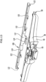
- eine perspektivische Darstellung der Saugdüse des Hartflächenabsauggeräts aus
Figur 1 ; - Figur 4:
- eine Draufsicht auf die Saugdüse aus
Figur 3 ; - Figur 5:
- eine Schnittansicht der Saugdüse längs der Linie 5-5 in
Figur 4 ; - Figur 6:
- eine Schnittansicht der Saugdüse längs der Linie 6-6 in
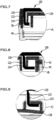
Figur 4 ; - Figur 7:
- eine vergrößerte Darstellung von Detail A aus
Figur 6 ; - Figur 8:
- eine vergrößerte Darstellung von Detail B aus
Figur 6 ; - Figur 9:
- eine vergrößerte Darstellung von Detail C aus
Figur 6 ; - Figur 10:
- eine perspektivische Darstellung der Saugdüse nach Art einer Explosionszeichnung, wobei eine Stützlippe ausgeblendet wurde;
- Figur 11:
- eine perspektivische Darstellung der Saugdüse schräg von oben, wobei ein Festlegeteil eine Freigabestellung einnimmt;
- Figur 12:
- eine perspektivische Darstellung der Saugdüse schräg von vorne, wobei das Festlegeteil eine Freigabestellung einnimmt;
- Figur 13:
- eine perspektivische Darstellung der Saugdüse schräg von hinten, wobei das Festlegeteil eine Freigabestellung einnimmt;
- Figur 14:
- eine schematische Darstellung eines hinteren Endabschnitts einer auswechselbaren Abziehlippe der Saugdüse, wobei der hintere Endabschnitt auf einem Stützrand eines Gehäuses der Saugdüse aufliegt und das Festlegeteil eine Festlegestellung einnimmt, in der eine Halteleiste des Festlegeteils auf dem hinteren Endabschnitt der Abziehlippe aufliegt;
- Figur 15:
- eine schematische Darstellung des hinteren Endabschnitts der Abziehlippe, nachdem das Festlegeteil vom Gehäuse getrennt wurde;
- Figur 16:
- eine schematische Darstellung des hinteren Endabschnitts der Abziehlippe, nachdem diese vom Stützrand des Gehäuses getrennt wurde.
- In den
Figuren 1 und2 ist eine vorteilhafte Ausführungsform eines erfindungsgemäßen tragbaren Hartflächenabsauggeräts schematisch dargestellt, das insgesamt mit dem Bezugszeichen 10 belegt ist. Das Hartflächenabsauggerät weist eine vorteilhafte Ausführungsform einer erfindungsgemäßen Saugdüse 12 auf, die in denFiguren 3 bis 16 schematisch dargestellt ist. - Mit Hilfe des tragbaren Hartflächenabsauggeräts 10 kann Flüssigkeit von einer Hartfläche, beispielsweise von einer Fensterscheibe, abgezogen und abgesaugt werden. Das Hartflächenabsauggerät 10 kann vom Benutzer nach Art eines manuellen Fensterabziehers an der Hartfläche entlang bewegt werden. Das tragbare Hartflächenabsauggerät 10 bildet insbesondere ein Fensterputzgerät aus.
- Das Hartflächenabsauggerät 10 umfasst einen Grundkörper 14 mit einem Grundgehäuse 16, das einen Handgriff 18 ausbildet und ein Saugaggregat 20 umgibt. Das Saugaggregat 20 weist eine Saugturbine 22 auf, die von einem Elektromotor 24 angetrieben wird. Der Elektromotor 24 wird von einer innerhalb des Handgriffs 18 angeordneten wiederaufladbaren Batterie 26 mit elektrischer Energie versorgt und kann mittels eines am Handgriff angeordneten Schalters 28 vom Benutzer ein- und ausgeschaltet werden.
- Das Grundgehäuse 16 bildet eine Abscheidekammer 30 aus, in der eine Abscheideeinrichtung 32, beispielsweise eine Prallwand, angeordnet ist und die vom Saugaggregat 20 mit Unterdruck beaufschlagt werden kann. Über einen in der Zeichnung nicht dargestellten Flüssigkeitsauslass steht die Abscheidekammer 30 mit einem Flüssigkeitstank 34 in Strömungsverbindung, der am Grundgehäuse 16 lösbar gehalten ist.
- Oberseitig schließt sich an den Grundkörper 14 die Saugdüse 12 an, die mit dem Grundkörper 14 steckbar verbindbar ist. Die Saugdüse 12 weist ein Gehäuse 36 auf, das von einer ersten Gehäusehalbschale 38 und einer zweiten Gehäusehalbschale 40 gebildet wird. Die beiden Gehäusehalbschalen 38, 40 sind mittels Verbindungsschrauben 42 miteinander verschraubt. Dies wird insbesondere aus den
Figuren 5 und12 deutlich. - An einer dem Grundkörper 14 abgewandten Gehäusestirnseite 44 des Gehäuses 36 ist eine Saugöffnung 46 angeordnet, an die sich ein Saugkanal 48 anschließt. Der Saugkanal 48 erstreckt sich durch das Gehäuse 36 hindurch und ragt mit einem hinteren Endabschnitt 50 aus einer Gehäuserückseite 52 des Gehäuses 36 heraus. Der hintere Endabschnitt 50 ist von einem Dichtring 54 umgeben und kann in einen Einlasskanal 56 des Grundgehäuses 16 eingesetzt werden zur Herstellung einer flüssigkeitsdichten und strömungsdichten Verbindung zwischen der Saugdüse 12 und dem Saugaggregat 20.
- An der Gehäusestirnseite 44 der Saugdüse 12 sind eine auswechselbare Abziehlippe 58 und eine Stützlippe 60 angeordnet. Die Abziehlippe 58 und die Stützlippe 60 sind elastisch verformbar.
- Die Stützlippe 60 ist mit der zweiten Gehäusehalbschale 40 stoffschlüssig verbunden. Im dargestellten Ausführungsbeispiel ist die Stützlippe 60 an die zweite Gehäusehalbschale 40 angeformt. Die Stützlippe 60 bildet in Kombination mit der zweiten Gehäusehalbschale 40 ein Spritzgussteil aus zwei Komponenten aus, wobei die Stützlippe 60 eine Weichkomponente des Spritzgussteils ausbildet und wobei die zweite Gehäusehalbschale 40 eine Hartkomponente des Spritzgussteils ausbildet.
- Die Abziehlippe 58 und die Stützlippe 60 ragen in die dem Saugkanal 48 abgewandte Richtung nach vorne aus dem Gehäuse 36 hervor. Die Abziehlippe 58 hintergreift hierbei das freie Ende 62 der Stützlippe 60. Sie weist einen sich an die Gehäusestirnseite 44 anschließenden Längsabschnitt 64 auf, an den sich ein zum Längsabschnitt 64 geneigter vorderer Endabschnitt 66 anschließt. Der vordere Endabschnitt 66 weist eine Abziehlippenkante 68 auf, die in der in der Zeichnung dargestellten unverformten Grundstellung vor dem freien Ende 62 der Stützlippe 60 angeordnet ist. Dies wird insbesondere aus
Figur 5 deutlich. - Auf der dem vorderen Endabschnitt 66 abgewandten Seite schließt sich an den Längsabschnitt 64 ein hinterer Endabschnitt 70 der Abziehlippe 58 an, der auf einem Stützrand 72 aufliegt. Der Stützrand 72 wird von der ersten Gehäusehalbschale 38 gebildet und schließt sich nach vorne an eine Stirnwand 74 der ersten Gehäusehalbschale 38 an. Der Stützrand 72 weist auf seiner der zweiten Gehäusehalbschale 40 abgewandten Oberseite 76 einen im Querschnitt V-förmigen Vorsprung 78 auf, der sich senkrecht zu einer Längsachse 80 der Saugdüse 12 von einem ersten Seitenrand 86 der Abziehlippe 58 bis zu einem zweiten Seitenrand 88 der Abziehlippe entlang des gesamten Stützrandes 72 erstreckt. Der hintere Endabschnitt 70 der Abziehlippe 58 weist auf seiner dem Stützrand 72 zugewandten Unterseite 82 einen Vorsprung 84 auf, der den Vorsprung 78 des Stützrandes 72 hintergreift und sich senkrecht zur Längsachse 80 über den gesamten hinteren Endabschnitt 70 erstreckt.
- Die Seitenränder 86 und 88 der Abziehlippe 58 sind parallel zur Längsachse 80 der Saugdüse 12 ausgerichtet. Im Abstand zu den Seitenrändern 86, 88 sind an der der Stützlippe 60 abgewandten Oberseite 90 der Abziehlippe 58 jeweils zwei parallel zur Längsachse 80 ausgerichtete Verstärkungsrippen 92, 94 bzw. 96, 98 angeordnet, die einer unzulässig starken Verformung der Abziehlippe 58 entgegenwirken.
- Zusätzlich zum Gehäuse 36 weist die Saugdüse 12 ein Festlegeteil 100 auf, das der Festlegung der auswechselbaren Abziehlippe 58 am Gehäuse 36 dient. Das Festlegeteil 100 ist relativ zum Gehäuse 36 zwischen einer in den
Figuren 3 bis 9 dargestellten Festlegestellung und einer in denFiguren 10 bis 13 dargestellten Freigabestellung hin und her bewegbar. Das Festlegeteil 100 kann vom Gehäuse 36 vollständig getrennt werden, wie dies in denFiguren 10 bis 13 dargestellt ist, und kann mit dem Gehäuse 36 lösbar verbunden werden. Das Festlegeteil 100 weist eine Halteleiste 102 auf, die sich in der Festlegestellung des Festlegeteils 100 vom ersten Seitenrand 86 bis zum zweiten Seitenrand 88 erstreckt und auf dem hinteren Endabschnitt 70 der auswechselbaren Abziehlippe 58 aufliegt, so dass die Abziehlippe 58 nicht aus dem Bereich zwischen der Halteleiste 102 und dem Stützrand 72 des Gehäuses 36 nach vorne herausgezogen werden kann. - Die erste Gehäusehalbschale 38 weist an ihrer der zweiten Gehäusehalbschale 40 abgewandten Oberseite eine Aufnahme 104 auf, die von einem ersten Aufnahmerand 106 der ersten Gehäusehalbschale 38 und einem zweiten Aufnahmerand 108 der ersten Gehäusehalbschale 38 begrenzt wird. Die beiden Aufnahmeränder 106, 108 umgeben die oberseitige Aufnahme 104 der ersten Gehäusehalbschale 38. Die Aufnahmeränder 106 und 108 weisen jeweils einen vorderen Randbereich 107 beziehungsweise 109 auf, der sich nach vorne über die Aufnahme 104 hinaus bis an das freie Ende des Stützrandes 72 erstreckt. Der Stützrand 72 wird somit seitlich von den Randbereichen 107, 109 der Aufnahmeränder 106, 108 begrenzt. Der hintere Endabschnitt 70 der auswechselbaren Abziehlippe 58 kann zwischen die Randbereiche 107, 109 der Aufnahmeränder 106, 108 eingesetzt und auf dem Stützrand 72 positioniert werden. Die Randbereiche 107, 109 bilden Anschlagflächen für die auswechselbare Abziehlippe 58 aus, so dass diese keine Bewegung quer zur Längsachse 80 ausführen kann.
- Das Festlegeteil 100 kann in die oberseitige Aufnahme 104 der ersten Gehäusehalbschale 38 eingesetzt werden, wobei sie die Aufnahme 104 in ihrer Festlegestellung vollständig ausfüllt. Das Festlegeteil 100 bildet hierzu eine Abdeckplatte 110 aus, die die Aufnahme 104 überdeckt.
- An seiner der Halteleiste 102 abgewandten Rückseite 112 weist das Festlegeteil 100 einen elastisch verformbaren Rasthaken 114 auf, der in der Festlegestellung in eine von der ersten Gehäusehalbschale 38 im Bereich des hinteren Endabschnitts 50 des Saugkanals 48 ausgebildeten Rastaufnahme 116 eintaucht und hierbei eine Querstrebe 118 der ersten Gehäusehalbschale 38 hintergreift. Dies wird insbesondere aus
Figur 5 deutlich. - An seiner der ersten Gehäusehalbschale 38 zugewandten Unterseite 120 trägt das Festlegeteil 100 mehrere im Abstand zueinander angeordnete erste Halteelemente 122, die jeweils L-förmig ausgestaltet sind. In der Festlegestellung des Festlegeteils 100 hintergreifen die ersten Halteelemente 122 jeweils ein rippenförmig oder L-förmig ausgestaltetes zweites Halteelement 124, das an einer Bodenwand 128 der Aufnahme 104 angeordnet ist. Dies wird insbesondere aus den
Figuren 7 bis 9 deutlich. - Die Bodenwand 128 wird von der ersten Gehäusehalbschale 38 gebildet und weist mittig eine Vertiefung 130 auf, die im Bereich des hinteren Endabschnitts 50 des Saugkanals 48 von der Querstrebe 118 überbrückt wird. Beim Einsetzen des Festlegeteils 100 in die Aufnahme 104 taucht der Rasthaken 114 zunächst in die Vertiefung 130 ein. Anschließend kann das Festlegeteil 100 entlang der Bodenwand 128 nach hinten verschoben werden, wobei die an der Unterseite 120 des Festlegeteils 100 angeordneten ersten Halteelemente 122 jeweils in eine Führungsöffnung 132 der Stirnwand 74 eintauchen, an die sich jeweils ein zweites Halteelement 124 anschließt. Das Festlegeteil 100 kann anschließend so weit nach hinten entlang der Bodenwand 128 verschoben werden, bis der Rasthaken 114 in die Rastaufnahme 116 der ersten Gehäusehalbschale 38 einschnappt und gleichzeitig die Abdeckplatte 110 des Festlegeteils 100 an den Aufnahemerändern 106 und 108 zur Anlage gelangt. Die ersten Halteelemente 122 bilden hierbei in Kombination mit den zweiten Halteelementen 124 eine Linearführung für das Festlegeteil 100 aus, so dass das Festlegeteil 100 entlang der Bodenwand 128 verschoben werden kann, ohne dass die Gefahr besteht, dass das Festlegeteil 100 verkantet.
- Die im Querschnitt L-förmig ausgestalteten ersten Halteelemente 122 hintergreifen die zweiten Halteelemente 124 beim Verschieben des Festlegeteils 100 entlang der Bodenwand 128, wobei das Festlegeteil 100 von der ersten Gehäusehalbschale 38 über die zweiten Halteelemente 124 und die ersten Halteelemente 122 mit einer Haltekraft beaufschlagt wird, unter deren Wirkung das Festlegeteil 100 gegen die erste Gehäusehalbschale 38 gedrückt wird. Dies hat zur Folge, dass die Halteleiste 102 gegen den hinteren Endabschnitt 50 der Abziehlippe gedrückt wird.
- Mit Hilfe des Festlegeteils 100 kann die auswechselbare Abziehlippe 58 am Gehäuse 36 der Saugdüse 12 festgelegt werden. Hierzu nimmt das Festlegeteil 100 seine Festlegestellung ein, in der der Halteleiste 102 des Festlegeteils 100 den hinteren Endabschnitt 70 der auswechselbaren Abziehlippe 58 überdeckt, so dass die Abziehlippe 58 am Gehäuse 36 festgelegt ist. Das Zusammenwirken der Halteleiste 102 mit dem hinteren Endabschnitt 70 der Abziehlippe 58 und dem Stützrand 72 in der Festlegestellung ist in
Figur 14 veranschaulicht. Soll die Abziehlippe 58 ausgewechselt werden, so kann der Benutzer - nachdem er die Saugdüse 12 vom Grundkörper 14 des Hartflächenabsauggeräts getrennt hat - den Rasthaken 114 aus der Rastaufnahme 116 herausdrücken und anschließend das Festlegeteil 100 in die inFigur 14 durch den Pfeil 138 veranschaulichte Richtung nach vorne verschieben, so dass die ersten Halteelemente 122 aus den Führungsöffnungen 132 heraustreten und das Festlegeteil 100 anschließend vollständig vom Gehäuse 36 der Saugdüse 12 getrennt werden kann. Dies ist inFigur 15 veranschaulicht. Die Abziehlippe 58 kann dann vom Benutzer ohne weiteres vom Stützrand 72 der ersten Gehäusehalbschale 38 entfernt werden, wie dies inFigur 16 veranschaulicht ist. Die Festlegung einer Abziehlippe 58 am Gehäuse 36 erfolgt in umgekehrter Reihenfolge, in dem die Abziehlippe 58 zunächst mit ihrem hinteren Endabschnitt 70 auf dem Stützrand 72 positioniert wird und anschließend das Festlegeteil 100 mit dem Gehäuse 36 verbunden wird, indem zunächst der Rasthaken 114 in die mittige Vertiefung 130 der Bodenwand 128 eingesetzt und anschließend das Festlegeteil entlang der Bodenwand 128 in seine Festlegestellung verschoben wird. - Wie bereits erwähnt, ist die Saugdüse 12 mit dem Grundkörper 14 des Hartflächenabsauggeräts 10 steckbar verbindbar. Hierzu kann der hintere Endabschnitt 50 des Saugkanals 48 in den Einlasskanal 56 des Grundgehäuses 16 eingesetzt werden. Mit Hilfe eines weiteren Rasthakens 134, der an der der ersten Gehäusehalbschale 38 abgewandten Unterseite 136 der zweiten Gehäusehalbschale 40 angeordnet ist, kann die Saugdüse 12 mit dem Grundgehäuse 16 verrastet werden. Der weitere Rasthaken 136 kann in eine in der Zeichnung nicht dargestellte Durchbrechung des Grundgehäuses 16 einrasten, und zum Entfernen der Saugdüse 12 vom Grundkörper 16 kann der Benutzer den weiteren Rasthaken 136 betätigen, so dass die Rastverbindung zwischen der Saugdüse 12 und dem Grundgehäuse 16 gelöst wird.
Claims (15)
- Saugdüse für ein tragbares Hartflächenabsauggerät zum Abziehen und Absaugen einer Flüssigkeit von einer Hartfläche, insbesondere von einer Fensterscheibe, mit einem Gehäuse (36), das an einer Gehäusestirnseite (44) eine Saugöffnung (46) aufweist, an die sich ein Saugkanal (48) anschließt, der an eine Unterdruckquelle anschließbar ist, und mit einer elastisch verformbaren Abziehlippe (58), die an der Gehäusestirnseite (44) auswechselbar gehalten ist, wobei die Saugdüse (12) ein relativ zum Gehäuse (36) zwischen einer Festlegestellung und einer Freigabestellung hin und her bewegbares Festlegeteil (100) aufweist, wobei die Abziehlippe (48) in der Festlegestellung des Festlegeteils (100) mit Hilfe des Festlegeteils (100) am Gehäuse (36) festlegbar und in der Freigabestellung des Festlegeteils (100) vom Gehäuse (36) trennbar ist, dadurch gekennzeichnet, dass das Festlegeteil (100) entlang einer Außenseite (90) des Gehäuses (36) verschiebbar ist.
- Saugdüse nach Anspruch 1, dadurch gekennzeichnet, dass das Gehäuse (36) einen Stützrand (72) aufweist, auf dem ein hinterer Endabschnitt (70) der Abziehlippe (58) positionierbar ist, und dass das Festlegeteil (100) eine Halteleiste (102) aufweist, die in der Festlegestellung des Festlegeteils (100) auf dem hinteren Endabschnitt (70) der Abziehlippe (58) positionierbar ist, vorzugsweise dass sich die Halteleiste (102) in der Festlegestellung des Festlegeteils (100) von einem ersten Seitenrand (86) der Abziehlippe (58) bis zu einem zweiten Seitenrand (88) der Abziehlippe (58) erstreckt.
- Saugdüse nach Anspruch 2, dadurch gekennzeichnet, dass der hintere Endabschnitt (70) der Abziehlippe (58) und der Stützrand (72) des Gehäuses (36) im Winkel zu einer Längsachse (80) der Saugdüse (12) ausgerichtete Vorsprünge (78, 84) aufweisen, die einander hintergreifen.
- Saugdüse nach einem der voranstehenden Ansprüche, dadurch gekennzeichnet, dass das Festlegeteil (100) mit dem Gehäuse (36) lösbar verbindbar ist, vorzugsweise dass das Festlegeteil (100) mit dem Gehäuse (36) lösbar verrastbar ist.
- Saugdüse nach einem der voranstehenden Ansprüche, dadurch gekennzeichnet, dass das Festlegeteil (100) mindestens ein erstes Rastelement (114) aufweist, das in der Festlegestellung ein am Gehäuse (36) angeordnetes zweites Rastelement (118) hintergreift.
- Saugdüse nach Anspruch 5, dadurch gekennzeichnet, dass das mindestens eine erste Rastelement (114) an einer Rückseite (112) des Festlegeteils (100) angeordnet ist und dass das mindestens eine zweite Rastelement (118) an einem aus einer Gehäuserückseite (52) des Gehäuses (36) herausragenden Endabschnitt (50) des Saugkanals (48) angeordnet ist.
- Saugdüse nach einem der voranstehenden Ansprüche, dadurch gekennzeichnet, dass das Festlegeteil (100) vom Gehäuse (36) trennbar ist.
- Saugdüse nach einem der voranstehenden Ansprüche, dadurch gekennzeichnet, dass das Festlegeteil (100) in der Festlegestellung eine Außenseite (90) des Gehäuses (36) zumindest teilweise überdeckt.
- Saugdüse nach einem der voranstehenden Ansprüche, dadurch gekennzeichnet, dass das Gehäuse (36) an einer Außenseite (90) eine Aufnahme (104) aufweist, in die das Festlegeteil (100) einsetzbar ist.
- Saugdüse nach einem der voranstehenden Ansprüche, dadurch gekennzeichnet, dass das Festlegeteil (100) in der Festlegestellung vom Gehäuse (36) mit einer Haltekraft in Richtung auf das Gehäuse (36) beaufschlagbar ist, vorzugsweise dass das Festlegeteil (100) mindestens ein erstes Halteelement (122) aufweist, das in der Festlegestellung des Festlegeteils (100) von einem ortsfest am Gehäuse (36) angeordneten zweiten Halteelement (124) mit einer Haltekraft in Richtung auf das Gehäuse (36) beaufschlagbar ist.
- Saugdüse nach Anspruch 10, dadurch gekennzeichnet, dass das mindestens eine erste Halteelement (122) in der Festlegestellung des Festlegeteils (100) ein zweites Halteelement (124) hintergreift.
- Saugdüse nach Anspruch 10 oder 11, dadurch gekennzeichnet, dass das mindestens eine erste Halteelement in Kombination mit einem zweiten Halteelement (124) gemeinsam eine Linearführung ausbildet zum Verschieben des Festlegeteils (100) relativ zum Gehäuse (36).
- Saugdüse nach Anspruch 10, 11 oder 12, dadurch gekennzeichnet, dass die ersten und/oder zweiten Halteelemente (122, 124) rippenförmig oder L-förmig ausgestaltet sind.
- Saugdüse nach einem der Ansprüche 10 bis 13, dadurch gekennzeichnet, dass das Gehäuse (36) Führungsöffnungen (132) aufweist, in die jeweils ein erstes Halteelement (122) einführbar ist, wobei innerhalb des Gehäuses (36) fluchtend zu den Führungsöffnungen (132) jeweils ein zweites Halteelement (124) angeordnet ist, vorzugsweise dass die Führungsöffnungen (132) an einer Stirnwand (74) des Gehäuses (36) angeordnet sind, an deren Außenseite sich die Abziehlippe (58) anschließt.
- Tragbares Hartflächenabsauggerät zum Abziehen und Absaugen einer Flüssigkeit von einer Hartfläche, insbesondere von einer Fensterscheibe, mit einer Saugdüse (12) nach einem der voranstehenden Ansprüchen, und mit einem Saugaggregat (20), das mit der Saugdüse (12) in Strömungsverbindung steht zum Absaugen eines Flüssigkeits-Luftgemisches von der Hartfläche, und mit einer Abscheideeinrichtung (32), die im Strömungsweg zwischen der Saugdüse (12) und dem Saugaggregat (20) angeordnet ist zum Abscheiden von Flüssigkeit aus dem abgesaugten Flüssigkeits-Luftgemisch, und mit einem Flüssigkeitstank (34) zur Aufnahme der abgeschiedenen Flüssigkeit.
Priority Applications (1)
| Application Number | Priority Date | Filing Date | Title |
|---|---|---|---|
| PL18707365.5T PL3758568T3 (pl) | 2018-02-26 | 2018-02-26 | Dysza ssąca i przenośne urządzenie odsysające do twardych powierzchni |
Applications Claiming Priority (1)
| Application Number | Priority Date | Filing Date | Title |
|---|---|---|---|
| PCT/EP2018/054675 WO2019161933A1 (de) | 2018-02-26 | 2018-02-26 | Saugdüse und tragbares hartflächenabsauggerät |
Publications (3)
| Publication Number | Publication Date |
|---|---|
| EP3758568A1 EP3758568A1 (de) | 2021-01-06 |
| EP3758568B1 true EP3758568B1 (de) | 2023-08-23 |
| EP3758568C0 EP3758568C0 (de) | 2023-08-23 |
Family
ID=61283244
Family Applications (1)
| Application Number | Title | Priority Date | Filing Date |
|---|---|---|---|
| EP18707365.5A Active EP3758568B1 (de) | 2018-02-26 | 2018-02-26 | Saugdüse und tragbares hartflächenabsauggerät |
Country Status (4)
| Country | Link |
|---|---|
| EP (1) | EP3758568B1 (de) |
| CN (1) | CN111683574A (de) |
| PL (1) | PL3758568T3 (de) |
| WO (1) | WO2019161933A1 (de) |
Citations (2)
| Publication number | Priority date | Publication date | Assignee | Title |
|---|---|---|---|---|
| DE202008018112U1 (de) * | 2008-01-11 | 2011-08-01 | Alfred Kärcher Gmbh & Co. Kg | Saugdüse |
| EP3195780B1 (de) * | 2016-01-22 | 2018-05-16 | Leifheit AG | Saugdüse |
Family Cites Families (5)
| Publication number | Priority date | Publication date | Assignee | Title |
|---|---|---|---|---|
| CN203042128U (zh) * | 2013-02-05 | 2013-07-10 | 朱厚林 | 一种改进的硬质表面的吸水器 |
| PL3185741T3 (pl) * | 2014-08-29 | 2020-04-30 | Alfred Kärcher SE & Co. KG | Dysza ssąca i urządzenie odsysające do twardych powierzchni |
| CN105327868B (zh) * | 2015-11-10 | 2017-10-31 | 朱厚林 | 一种硬质表面吸水清洁器 |
| CN205458475U (zh) * | 2016-01-18 | 2016-08-17 | 朱厚林 | 一种硬质表面吸水清洁器的刮头 |
| CN107212799A (zh) * | 2016-03-22 | 2017-09-29 | 宁波永冠电器有限公司 | 一种多功能吸尘清洁一体机 |
-
2018
- 2018-02-26 EP EP18707365.5A patent/EP3758568B1/de active Active
- 2018-02-26 PL PL18707365.5T patent/PL3758568T3/pl unknown
- 2018-02-26 CN CN201880088498.8A patent/CN111683574A/zh active Pending
- 2018-02-26 WO PCT/EP2018/054675 patent/WO2019161933A1/de not_active Ceased
Patent Citations (2)
| Publication number | Priority date | Publication date | Assignee | Title |
|---|---|---|---|---|
| DE202008018112U1 (de) * | 2008-01-11 | 2011-08-01 | Alfred Kärcher Gmbh & Co. Kg | Saugdüse |
| EP3195780B1 (de) * | 2016-01-22 | 2018-05-16 | Leifheit AG | Saugdüse |
Also Published As
| Publication number | Publication date |
|---|---|
| CN111683574A (zh) | 2020-09-18 |
| EP3758568A1 (de) | 2021-01-06 |
| EP3758568C0 (de) | 2023-08-23 |
| WO2019161933A1 (de) | 2019-08-29 |
| PL3758568T3 (pl) | 2024-03-04 |
Similar Documents
| Publication | Publication Date | Title |
|---|---|---|
| EP3021727B1 (de) | Tragbares hartflächenreinigungsgerät | |
| EP3393319B1 (de) | Saugdüse für ein hartflächenreinigungsgerät und hartflächenreinigungsgerät mit einer derartigen saugdüse | |
| EP2638839B1 (de) | Saugdüse mit Abstreiflippen | |
| EP3021722B1 (de) | Tragbares hartflächenreinigungsgerät | |
| EP3746233B1 (de) | Hochdruckreinigungsgerät | |
| EP3021723B2 (de) | Tragbares hartflächenreinigungsgerät | |
| EP3681360B1 (de) | Flächenreinigungsgerät | |
| WO2014032712A1 (de) | Hartflächenabsaugsystem mit verlängerungseinrichtung | |
| EP3185741A1 (de) | Saugdüse und hartflächenabsauggerät | |
| WO2017108088A1 (de) | Saugdüse für ein hartflächenreinigungsgerät und hartflächenreinigungsgerät mit einer derartigen saugdüse | |
| DE3136401C2 (de) | Mehrzweck-Reinigungsgerät | |
| EP3518720B1 (de) | Saugdüse und hartflächenabsauggerät | |
| WO2016162087A1 (de) | Tauchpumpe mit einem vorfilter | |
| EP3758568B1 (de) | Saugdüse und tragbares hartflächenabsauggerät | |
| EP3681361B1 (de) | Flächenreinigungsgerät | |
| EP3393322B1 (de) | Tragbares hartflächenreinigungsgerät | |
| EP3021724B1 (de) | Tragbares hartflächenreinigungsgerät | |
| EP3006636B1 (de) | Wandablauf mit Pumpe | |
| DE202014011047U1 (de) | Saugdüse und Hartflächenabsauggerät | |
| EP0286692B1 (de) | Gerät zum Reinigen von planen Flächen | |
| DE10056928B4 (de) | Vorrichtung zur Reinigung von wiederholt verwendeten Werkzeugen | |
| DE102013011004A1 (de) | Vorrichtung zur Reinigung glatter Oberflächen |
Legal Events
| Date | Code | Title | Description |
|---|---|---|---|
| STAA | Information on the status of an ep patent application or granted ep patent |
Free format text: STATUS: UNKNOWN |
|
| STAA | Information on the status of an ep patent application or granted ep patent |
Free format text: STATUS: THE INTERNATIONAL PUBLICATION HAS BEEN MADE |
|
| PUAI | Public reference made under article 153(3) epc to a published international application that has entered the european phase |
Free format text: ORIGINAL CODE: 0009012 |
|
| STAA | Information on the status of an ep patent application or granted ep patent |
Free format text: STATUS: REQUEST FOR EXAMINATION WAS MADE |
|
| 17P | Request for examination filed |
Effective date: 20200716 |
|
| AK | Designated contracting states |
Kind code of ref document: A1 Designated state(s): AL AT BE BG CH CY CZ DE DK EE ES FI FR GB GR HR HU IE IS IT LI LT LU LV MC MK MT NL NO PL PT RO RS SE SI SK SM TR |
|
| AX | Request for extension of the european patent |
Extension state: BA ME |
|
| DAV | Request for validation of the european patent (deleted) | ||
| DAX | Request for extension of the european patent (deleted) | ||
| GRAP | Despatch of communication of intention to grant a patent |
Free format text: ORIGINAL CODE: EPIDOSNIGR1 |
|
| STAA | Information on the status of an ep patent application or granted ep patent |
Free format text: STATUS: GRANT OF PATENT IS INTENDED |
|
| INTG | Intention to grant announced |
Effective date: 20230322 |
|
| P01 | Opt-out of the competence of the unified patent court (upc) registered |
Effective date: 20230521 |
|
| GRAS | Grant fee paid |
Free format text: ORIGINAL CODE: EPIDOSNIGR3 |
|
| GRAA | (expected) grant |
Free format text: ORIGINAL CODE: 0009210 |
|
| STAA | Information on the status of an ep patent application or granted ep patent |
Free format text: STATUS: THE PATENT HAS BEEN GRANTED |
|
| AK | Designated contracting states |
Kind code of ref document: B1 Designated state(s): AL AT BE BG CH CY CZ DE DK EE ES FI FR GB GR HR HU IE IS IT LI LT LU LV MC MK MT NL NO PL PT RO RS SE SI SK SM TR |
|
| REG | Reference to a national code |
Ref country code: GB Ref legal event code: FG4D Free format text: NOT ENGLISH |
|
| REG | Reference to a national code |
Ref country code: CH Ref legal event code: EP |
|
| REG | Reference to a national code |
Ref country code: DE Ref legal event code: R096 Ref document number: 502018013041 Country of ref document: DE |
|
| REG | Reference to a national code |
Ref country code: IE Ref legal event code: FG4D Free format text: LANGUAGE OF EP DOCUMENT: GERMAN |
|
| U01 | Request for unitary effect filed |
Effective date: 20230920 |
|
| U07 | Unitary effect registered |
Designated state(s): AT BE BG DE DK EE FI FR IT LT LU LV MT NL PT SE SI Effective date: 20230926 |
|
| P04 | Withdrawal of opt-out of the competence of the unified patent court (upc) registered |
Effective date: 20230922 |
|
| PG25 | Lapsed in a contracting state [announced via postgrant information from national office to epo] |
Ref country code: GR Free format text: LAPSE BECAUSE OF FAILURE TO SUBMIT A TRANSLATION OF THE DESCRIPTION OR TO PAY THE FEE WITHIN THE PRESCRIBED TIME-LIMIT Effective date: 20231124 |
|
| PG25 | Lapsed in a contracting state [announced via postgrant information from national office to epo] |
Ref country code: IS Free format text: LAPSE BECAUSE OF FAILURE TO SUBMIT A TRANSLATION OF THE DESCRIPTION OR TO PAY THE FEE WITHIN THE PRESCRIBED TIME-LIMIT Effective date: 20231223 |
|
| PG25 | Lapsed in a contracting state [announced via postgrant information from national office to epo] |
Ref country code: RS Free format text: LAPSE BECAUSE OF FAILURE TO SUBMIT A TRANSLATION OF THE DESCRIPTION OR TO PAY THE FEE WITHIN THE PRESCRIBED TIME-LIMIT Effective date: 20230823 Ref country code: NO Free format text: LAPSE BECAUSE OF FAILURE TO SUBMIT A TRANSLATION OF THE DESCRIPTION OR TO PAY THE FEE WITHIN THE PRESCRIBED TIME-LIMIT Effective date: 20231123 Ref country code: IS Free format text: LAPSE BECAUSE OF FAILURE TO SUBMIT A TRANSLATION OF THE DESCRIPTION OR TO PAY THE FEE WITHIN THE PRESCRIBED TIME-LIMIT Effective date: 20231223 Ref country code: HR Free format text: LAPSE BECAUSE OF FAILURE TO SUBMIT A TRANSLATION OF THE DESCRIPTION OR TO PAY THE FEE WITHIN THE PRESCRIBED TIME-LIMIT Effective date: 20230823 Ref country code: GR Free format text: LAPSE BECAUSE OF FAILURE TO SUBMIT A TRANSLATION OF THE DESCRIPTION OR TO PAY THE FEE WITHIN THE PRESCRIBED TIME-LIMIT Effective date: 20231124 |
|
| U20 | Renewal fee for the european patent with unitary effect paid |
Year of fee payment: 7 Effective date: 20240226 |
|
| PG25 | Lapsed in a contracting state [announced via postgrant information from national office to epo] |
Ref country code: ES Free format text: LAPSE BECAUSE OF FAILURE TO SUBMIT A TRANSLATION OF THE DESCRIPTION OR TO PAY THE FEE WITHIN THE PRESCRIBED TIME-LIMIT Effective date: 20230823 |
|
| PG25 | Lapsed in a contracting state [announced via postgrant information from national office to epo] |
Ref country code: SM Free format text: LAPSE BECAUSE OF FAILURE TO SUBMIT A TRANSLATION OF THE DESCRIPTION OR TO PAY THE FEE WITHIN THE PRESCRIBED TIME-LIMIT Effective date: 20230823 Ref country code: RO Free format text: LAPSE BECAUSE OF FAILURE TO SUBMIT A TRANSLATION OF THE DESCRIPTION OR TO PAY THE FEE WITHIN THE PRESCRIBED TIME-LIMIT Effective date: 20230823 Ref country code: ES Free format text: LAPSE BECAUSE OF FAILURE TO SUBMIT A TRANSLATION OF THE DESCRIPTION OR TO PAY THE FEE WITHIN THE PRESCRIBED TIME-LIMIT Effective date: 20230823 Ref country code: CZ Free format text: LAPSE BECAUSE OF FAILURE TO SUBMIT A TRANSLATION OF THE DESCRIPTION OR TO PAY THE FEE WITHIN THE PRESCRIBED TIME-LIMIT Effective date: 20230823 Ref country code: SK Free format text: LAPSE BECAUSE OF FAILURE TO SUBMIT A TRANSLATION OF THE DESCRIPTION OR TO PAY THE FEE WITHIN THE PRESCRIBED TIME-LIMIT Effective date: 20230823 |
|
| REG | Reference to a national code |
Ref country code: DE Ref legal event code: R097 Ref document number: 502018013041 Country of ref document: DE |
|
| PLBE | No opposition filed within time limit |
Free format text: ORIGINAL CODE: 0009261 |
|
| STAA | Information on the status of an ep patent application or granted ep patent |
Free format text: STATUS: NO OPPOSITION FILED WITHIN TIME LIMIT |
|
| 26N | No opposition filed |
Effective date: 20240524 |
|
| PG25 | Lapsed in a contracting state [announced via postgrant information from national office to epo] |
Ref country code: MC Free format text: LAPSE BECAUSE OF FAILURE TO SUBMIT A TRANSLATION OF THE DESCRIPTION OR TO PAY THE FEE WITHIN THE PRESCRIBED TIME-LIMIT Effective date: 20230823 |
|
| REG | Reference to a national code |
Ref country code: CH Ref legal event code: PL |
|
| PG25 | Lapsed in a contracting state [announced via postgrant information from national office to epo] |
Ref country code: CH Free format text: LAPSE BECAUSE OF NON-PAYMENT OF DUE FEES Effective date: 20240229 |
|
| PG25 | Lapsed in a contracting state [announced via postgrant information from national office to epo] |
Ref country code: CH Free format text: LAPSE BECAUSE OF NON-PAYMENT OF DUE FEES Effective date: 20240229 |
|
| P05 | Withdrawal of opt-out of the competence of the unified patent court (upc) changed |
Free format text: CASE NUMBER: APP_574607/2023 Effective date: 20230926 |
|
| PGFP | Annual fee paid to national office [announced via postgrant information from national office to epo] |
Ref country code: PL Payment date: 20241212 Year of fee payment: 8 |
|
| PG25 | Lapsed in a contracting state [announced via postgrant information from national office to epo] |
Ref country code: IE Free format text: LAPSE BECAUSE OF NON-PAYMENT OF DUE FEES Effective date: 20240226 |
|
| PG25 | Lapsed in a contracting state [announced via postgrant information from national office to epo] |
Ref country code: IE Free format text: LAPSE BECAUSE OF NON-PAYMENT OF DUE FEES Effective date: 20240226 |
|
| U20 | Renewal fee for the european patent with unitary effect paid |
Year of fee payment: 8 Effective date: 20250224 |
|
| PG25 | Lapsed in a contracting state [announced via postgrant information from national office to epo] |
Ref country code: CY Free format text: LAPSE BECAUSE OF FAILURE TO SUBMIT A TRANSLATION OF THE DESCRIPTION OR TO PAY THE FEE WITHIN THE PRESCRIBED TIME-LIMIT; INVALID AB INITIO Effective date: 20180226 |
|
| PG25 | Lapsed in a contracting state [announced via postgrant information from national office to epo] |
Ref country code: HU Free format text: LAPSE BECAUSE OF FAILURE TO SUBMIT A TRANSLATION OF THE DESCRIPTION OR TO PAY THE FEE WITHIN THE PRESCRIBED TIME-LIMIT; INVALID AB INITIO Effective date: 20180226 |
|
| PG25 | Lapsed in a contracting state [announced via postgrant information from national office to epo] |
Ref country code: TR Free format text: LAPSE BECAUSE OF FAILURE TO SUBMIT A TRANSLATION OF THE DESCRIPTION OR TO PAY THE FEE WITHIN THE PRESCRIBED TIME-LIMIT Effective date: 20230823 |
|
| U20 | Renewal fee for the european patent with unitary effect paid |
Year of fee payment: 9 Effective date: 20260204 |
|
| PGFP | Annual fee paid to national office [announced via postgrant information from national office to epo] |
Ref country code: GB Payment date: 20260119 Year of fee payment: 9 |